EP4527587A1 - Method for preparing photovoltaic module integrated with vehicle body - Google Patents
Method for preparing photovoltaic module integrated with vehicle body Download PDFInfo
- Publication number
- EP4527587A1 EP4527587A1 EP23806857.1A EP23806857A EP4527587A1 EP 4527587 A1 EP4527587 A1 EP 4527587A1 EP 23806857 A EP23806857 A EP 23806857A EP 4527587 A1 EP4527587 A1 EP 4527587A1
- Authority
- EP
- European Patent Office
- Prior art keywords
- thermoplastic material
- mold
- photovoltaic module
- vehicle body
- upper mold
- Prior art date
- Legal status (The legal status is an assumption and is not a legal conclusion. Google has not performed a legal analysis and makes no representation as to the accuracy of the status listed.)
- Pending
Links
Images






Classifications
-
- B—PERFORMING OPERATIONS; TRANSPORTING
- B29—WORKING OF PLASTICS; WORKING OF SUBSTANCES IN A PLASTIC STATE IN GENERAL
- B29C—SHAPING OR JOINING OF PLASTICS; SHAPING OF MATERIAL IN A PLASTIC STATE, NOT OTHERWISE PROVIDED FOR; AFTER-TREATMENT OF THE SHAPED PRODUCTS, e.g. REPAIRING
- B29C51/00—Shaping by thermoforming, i.e. shaping sheets or sheet like preforms after heating, e.g. shaping sheets in matched moulds or by deep-drawing; Apparatus therefor
- B29C51/12—Shaping by thermoforming, i.e. shaping sheets or sheet like preforms after heating, e.g. shaping sheets in matched moulds or by deep-drawing; Apparatus therefor of articles having inserts or reinforcements
-
- B—PERFORMING OPERATIONS; TRANSPORTING
- B32—LAYERED PRODUCTS
- B32B—LAYERED PRODUCTS, i.e. PRODUCTS BUILT-UP OF STRATA OF FLAT OR NON-FLAT, e.g. CELLULAR OR HONEYCOMB, FORM
- B32B37/00—Methods or apparatus for laminating, e.g. by curing or by ultrasonic bonding
- B32B37/10—Methods or apparatus for laminating, e.g. by curing or by ultrasonic bonding characterised by the pressing technique, e.g. using action of vacuum or fluid pressure
-
- B—PERFORMING OPERATIONS; TRANSPORTING
- B29—WORKING OF PLASTICS; WORKING OF SUBSTANCES IN A PLASTIC STATE IN GENERAL
- B29C—SHAPING OR JOINING OF PLASTICS; SHAPING OF MATERIAL IN A PLASTIC STATE, NOT OTHERWISE PROVIDED FOR; AFTER-TREATMENT OF THE SHAPED PRODUCTS, e.g. REPAIRING
- B29C43/00—Compression moulding, i.e. applying external pressure to flow the moulding material; Apparatus therefor
- B29C43/02—Compression moulding, i.e. applying external pressure to flow the moulding material; Apparatus therefor of articles of definite length, i.e. discrete articles
- B29C43/18—Compression moulding, i.e. applying external pressure to flow the moulding material; Apparatus therefor of articles of definite length, i.e. discrete articles incorporating preformed parts or layers, e.g. compression moulding around inserts or for coating articles
-
- B—PERFORMING OPERATIONS; TRANSPORTING
- B29—WORKING OF PLASTICS; WORKING OF SUBSTANCES IN A PLASTIC STATE IN GENERAL
- B29C—SHAPING OR JOINING OF PLASTICS; SHAPING OF MATERIAL IN A PLASTIC STATE, NOT OTHERWISE PROVIDED FOR; AFTER-TREATMENT OF THE SHAPED PRODUCTS, e.g. REPAIRING
- B29C43/00—Compression moulding, i.e. applying external pressure to flow the moulding material; Apparatus therefor
- B29C43/32—Component parts, details or accessories; Auxiliary operations
- B29C43/36—Moulds for making articles of definite length, i.e. discrete articles
-
- B—PERFORMING OPERATIONS; TRANSPORTING
- B29—WORKING OF PLASTICS; WORKING OF SUBSTANCES IN A PLASTIC STATE IN GENERAL
- B29C—SHAPING OR JOINING OF PLASTICS; SHAPING OF MATERIAL IN A PLASTIC STATE, NOT OTHERWISE PROVIDED FOR; AFTER-TREATMENT OF THE SHAPED PRODUCTS, e.g. REPAIRING
- B29C43/00—Compression moulding, i.e. applying external pressure to flow the moulding material; Apparatus therefor
- B29C43/32—Component parts, details or accessories; Auxiliary operations
- B29C43/58—Measuring, controlling or regulating
-
- B—PERFORMING OPERATIONS; TRANSPORTING
- B60—VEHICLES IN GENERAL
- B60K—ARRANGEMENT OR MOUNTING OF PROPULSION UNITS OR OF TRANSMISSIONS IN VEHICLES; ARRANGEMENT OR MOUNTING OF PLURAL DIVERSE PRIME-MOVERS IN VEHICLES; AUXILIARY DRIVES FOR VEHICLES; INSTRUMENTATION OR DASHBOARDS FOR VEHICLES; ARRANGEMENTS IN CONNECTION WITH COOLING, AIR INTAKE, GAS EXHAUST OR FUEL SUPPLY OF PROPULSION UNITS IN VEHICLES
- B60K16/00—Arrangements in connection with power supply of propulsion units in vehicles from forces of nature, e.g. sun or wind
-
- B—PERFORMING OPERATIONS; TRANSPORTING
- B62—LAND VEHICLES FOR TRAVELLING OTHERWISE THAN ON RAILS
- B62D—MOTOR VEHICLES; TRAILERS
- B62D29/00—Superstructures, understructures, or sub-units thereof, characterised by the material thereof
- B62D29/04—Superstructures, understructures, or sub-units thereof, characterised by the material thereof predominantly of synthetic material
- B62D29/043—Superstructures
-
- H—ELECTRICITY
- H10—SEMICONDUCTOR DEVICES; ELECTRIC SOLID-STATE DEVICES NOT OTHERWISE PROVIDED FOR
- H10F—INORGANIC SEMICONDUCTOR DEVICES SENSITIVE TO INFRARED RADIATION, LIGHT, ELECTROMAGNETIC RADIATION OF SHORTER WAVELENGTH OR CORPUSCULAR RADIATION
- H10F19/00—Integrated devices, or assemblies of multiple devices, comprising at least one photovoltaic cell covered by group H10F10/00, e.g. photovoltaic modules
- H10F19/80—Encapsulations or containers for integrated devices, or assemblies of multiple devices, having photovoltaic cells
-
- B—PERFORMING OPERATIONS; TRANSPORTING
- B29—WORKING OF PLASTICS; WORKING OF SUBSTANCES IN A PLASTIC STATE IN GENERAL
- B29C—SHAPING OR JOINING OF PLASTICS; SHAPING OF MATERIAL IN A PLASTIC STATE, NOT OTHERWISE PROVIDED FOR; AFTER-TREATMENT OF THE SHAPED PRODUCTS, e.g. REPAIRING
- B29C43/00—Compression moulding, i.e. applying external pressure to flow the moulding material; Apparatus therefor
- B29C43/02—Compression moulding, i.e. applying external pressure to flow the moulding material; Apparatus therefor of articles of definite length, i.e. discrete articles
- B29C43/18—Compression moulding, i.e. applying external pressure to flow the moulding material; Apparatus therefor of articles of definite length, i.e. discrete articles incorporating preformed parts or layers, e.g. compression moulding around inserts or for coating articles
- B29C2043/181—Compression moulding, i.e. applying external pressure to flow the moulding material; Apparatus therefor of articles of definite length, i.e. discrete articles incorporating preformed parts or layers, e.g. compression moulding around inserts or for coating articles encapsulated
- B29C2043/182—Compression moulding, i.e. applying external pressure to flow the moulding material; Apparatus therefor of articles of definite length, i.e. discrete articles incorporating preformed parts or layers, e.g. compression moulding around inserts or for coating articles encapsulated completely
-
- B—PERFORMING OPERATIONS; TRANSPORTING
- B29—WORKING OF PLASTICS; WORKING OF SUBSTANCES IN A PLASTIC STATE IN GENERAL
- B29C—SHAPING OR JOINING OF PLASTICS; SHAPING OF MATERIAL IN A PLASTIC STATE, NOT OTHERWISE PROVIDED FOR; AFTER-TREATMENT OF THE SHAPED PRODUCTS, e.g. REPAIRING
- B29C43/00—Compression moulding, i.e. applying external pressure to flow the moulding material; Apparatus therefor
- B29C43/32—Component parts, details or accessories; Auxiliary operations
- B29C43/58—Measuring, controlling or regulating
- B29C2043/5816—Measuring, controlling or regulating temperature
-
- B—PERFORMING OPERATIONS; TRANSPORTING
- B29—WORKING OF PLASTICS; WORKING OF SUBSTANCES IN A PLASTIC STATE IN GENERAL
- B29C—SHAPING OR JOINING OF PLASTICS; SHAPING OF MATERIAL IN A PLASTIC STATE, NOT OTHERWISE PROVIDED FOR; AFTER-TREATMENT OF THE SHAPED PRODUCTS, e.g. REPAIRING
- B29C43/00—Compression moulding, i.e. applying external pressure to flow the moulding material; Apparatus therefor
- B29C43/02—Compression moulding, i.e. applying external pressure to flow the moulding material; Apparatus therefor of articles of definite length, i.e. discrete articles
- B29C43/20—Making multilayered or multicoloured articles
-
- B—PERFORMING OPERATIONS; TRANSPORTING
- B29—WORKING OF PLASTICS; WORKING OF SUBSTANCES IN A PLASTIC STATE IN GENERAL
- B29C—SHAPING OR JOINING OF PLASTICS; SHAPING OF MATERIAL IN A PLASTIC STATE, NOT OTHERWISE PROVIDED FOR; AFTER-TREATMENT OF THE SHAPED PRODUCTS, e.g. REPAIRING
- B29C51/00—Shaping by thermoforming, i.e. shaping sheets or sheet like preforms after heating, e.g. shaping sheets in matched moulds or by deep-drawing; Apparatus therefor
- B29C51/08—Deep drawing or matched-mould forming, i.e. using mechanical means only
- B29C51/082—Deep drawing or matched-mould forming, i.e. using mechanical means only by shaping between complementary mould parts
-
- B—PERFORMING OPERATIONS; TRANSPORTING
- B29—WORKING OF PLASTICS; WORKING OF SUBSTANCES IN A PLASTIC STATE IN GENERAL
- B29C—SHAPING OR JOINING OF PLASTICS; SHAPING OF MATERIAL IN A PLASTIC STATE, NOT OTHERWISE PROVIDED FOR; AFTER-TREATMENT OF THE SHAPED PRODUCTS, e.g. REPAIRING
- B29C51/00—Shaping by thermoforming, i.e. shaping sheets or sheet like preforms after heating, e.g. shaping sheets in matched moulds or by deep-drawing; Apparatus therefor
- B29C51/14—Shaping by thermoforming, i.e. shaping sheets or sheet like preforms after heating, e.g. shaping sheets in matched moulds or by deep-drawing; Apparatus therefor using multilayered preforms or sheets
-
- B—PERFORMING OPERATIONS; TRANSPORTING
- B29—WORKING OF PLASTICS; WORKING OF SUBSTANCES IN A PLASTIC STATE IN GENERAL
- B29K—INDEXING SCHEME ASSOCIATED WITH SUBCLASSES B29B, B29C OR B29D, RELATING TO MOULDING MATERIALS OR TO MATERIALS FOR MOULDS, REINFORCEMENTS, FILLERS OR PREFORMED PARTS, e.g. INSERTS
- B29K2069/00—Use of PC, i.e. polycarbonates or derivatives thereof, as moulding material
-
- B—PERFORMING OPERATIONS; TRANSPORTING
- B29—WORKING OF PLASTICS; WORKING OF SUBSTANCES IN A PLASTIC STATE IN GENERAL
- B29K—INDEXING SCHEME ASSOCIATED WITH SUBCLASSES B29B, B29C OR B29D, RELATING TO MOULDING MATERIALS OR TO MATERIALS FOR MOULDS, REINFORCEMENTS, FILLERS OR PREFORMED PARTS, e.g. INSERTS
- B29K2101/00—Use of unspecified macromolecular compounds as moulding material
- B29K2101/12—Thermoplastic materials
-
- B—PERFORMING OPERATIONS; TRANSPORTING
- B29—WORKING OF PLASTICS; WORKING OF SUBSTANCES IN A PLASTIC STATE IN GENERAL
- B29K—INDEXING SCHEME ASSOCIATED WITH SUBCLASSES B29B, B29C OR B29D, RELATING TO MOULDING MATERIALS OR TO MATERIALS FOR MOULDS, REINFORCEMENTS, FILLERS OR PREFORMED PARTS, e.g. INSERTS
- B29K2307/00—Use of elements other than metals as reinforcement
- B29K2307/04—Carbon
-
- B—PERFORMING OPERATIONS; TRANSPORTING
- B29—WORKING OF PLASTICS; WORKING OF SUBSTANCES IN A PLASTIC STATE IN GENERAL
- B29K—INDEXING SCHEME ASSOCIATED WITH SUBCLASSES B29B, B29C OR B29D, RELATING TO MOULDING MATERIALS OR TO MATERIALS FOR MOULDS, REINFORCEMENTS, FILLERS OR PREFORMED PARTS, e.g. INSERTS
- B29K2309/00—Use of inorganic materials not provided for in groups B29K2303/00 - B29K2307/00, as reinforcement
- B29K2309/08—Glass
-
- B—PERFORMING OPERATIONS; TRANSPORTING
- B29—WORKING OF PLASTICS; WORKING OF SUBSTANCES IN A PLASTIC STATE IN GENERAL
- B29K—INDEXING SCHEME ASSOCIATED WITH SUBCLASSES B29B, B29C OR B29D, RELATING TO MOULDING MATERIALS OR TO MATERIALS FOR MOULDS, REINFORCEMENTS, FILLERS OR PREFORMED PARTS, e.g. INSERTS
- B29K2995/00—Properties of moulding materials, reinforcements, fillers, preformed parts or moulds
- B29K2995/0018—Properties of moulding materials, reinforcements, fillers, preformed parts or moulds having particular optical properties, e.g. fluorescent or phosphorescent
- B29K2995/0026—Transparent
-
- B—PERFORMING OPERATIONS; TRANSPORTING
- B29—WORKING OF PLASTICS; WORKING OF SUBSTANCES IN A PLASTIC STATE IN GENERAL
- B29L—INDEXING SCHEME ASSOCIATED WITH SUBCLASS B29C, RELATING TO PARTICULAR ARTICLES
- B29L2031/00—Other particular articles
- B29L2031/30—Vehicles, e.g. ships or aircraft, or body parts thereof
-
- B—PERFORMING OPERATIONS; TRANSPORTING
- B29—WORKING OF PLASTICS; WORKING OF SUBSTANCES IN A PLASTIC STATE IN GENERAL
- B29L—INDEXING SCHEME ASSOCIATED WITH SUBCLASS B29C, RELATING TO PARTICULAR ARTICLES
- B29L2031/00—Other particular articles
- B29L2031/30—Vehicles, e.g. ships or aircraft, or body parts thereof
- B29L2031/3005—Body finishings
-
- B—PERFORMING OPERATIONS; TRANSPORTING
- B29—WORKING OF PLASTICS; WORKING OF SUBSTANCES IN A PLASTIC STATE IN GENERAL
- B29L—INDEXING SCHEME ASSOCIATED WITH SUBCLASS B29C, RELATING TO PARTICULAR ARTICLES
- B29L2031/00—Other particular articles
- B29L2031/30—Vehicles, e.g. ships or aircraft, or body parts thereof
- B29L2031/3055—Cars
-
- B—PERFORMING OPERATIONS; TRANSPORTING
- B60—VEHICLES IN GENERAL
- B60K—ARRANGEMENT OR MOUNTING OF PROPULSION UNITS OR OF TRANSMISSIONS IN VEHICLES; ARRANGEMENT OR MOUNTING OF PLURAL DIVERSE PRIME-MOVERS IN VEHICLES; AUXILIARY DRIVES FOR VEHICLES; INSTRUMENTATION OR DASHBOARDS FOR VEHICLES; ARRANGEMENTS IN CONNECTION WITH COOLING, AIR INTAKE, GAS EXHAUST OR FUEL SUPPLY OF PROPULSION UNITS IN VEHICLES
- B60K16/00—Arrangements in connection with power supply of propulsion units in vehicles from forces of nature, e.g. sun or wind
- B60K2016/003—Arrangements in connection with power supply of propulsion units in vehicles from forces of nature, e.g. sun or wind solar power driven
-
- Y—GENERAL TAGGING OF NEW TECHNOLOGICAL DEVELOPMENTS; GENERAL TAGGING OF CROSS-SECTIONAL TECHNOLOGIES SPANNING OVER SEVERAL SECTIONS OF THE IPC; TECHNICAL SUBJECTS COVERED BY FORMER USPC CROSS-REFERENCE ART COLLECTIONS [XRACs] AND DIGESTS
- Y02—TECHNOLOGIES OR APPLICATIONS FOR MITIGATION OR ADAPTATION AGAINST CLIMATE CHANGE
- Y02E—REDUCTION OF GREENHOUSE GAS [GHG] EMISSIONS, RELATED TO ENERGY GENERATION, TRANSMISSION OR DISTRIBUTION
- Y02E10/00—Energy generation through renewable energy sources
- Y02E10/50—Photovoltaic [PV] energy
-
- Y—GENERAL TAGGING OF NEW TECHNOLOGICAL DEVELOPMENTS; GENERAL TAGGING OF CROSS-SECTIONAL TECHNOLOGIES SPANNING OVER SEVERAL SECTIONS OF THE IPC; TECHNICAL SUBJECTS COVERED BY FORMER USPC CROSS-REFERENCE ART COLLECTIONS [XRACs] AND DIGESTS
- Y02—TECHNOLOGIES OR APPLICATIONS FOR MITIGATION OR ADAPTATION AGAINST CLIMATE CHANGE
- Y02T—CLIMATE CHANGE MITIGATION TECHNOLOGIES RELATED TO TRANSPORTATION
- Y02T10/00—Road transport of goods or passengers
- Y02T10/80—Technologies aiming to reduce greenhouse gasses emissions common to all road transportation technologies
- Y02T10/90—Energy harvesting concepts as power supply for auxiliaries' energy consumption, e.g. photovoltaic sun-roof
Definitions
- the present invention relates to the technical field of photovoltaic technology, particularly relates to photovoltaic module and fabricating method thereof.
- the brackets or photovoltaic modules is arranged on the roof, or the vehicle body that will affect the appearance, the weight and the wind resistance also may be increased, which in turn will increase the fuel consumption or power consumption of the vehicle.
- the way of encapsulating photovoltaic cells with double-layer glass to make roof skylights or roofs can only be limited to the roof of vehicle. With the increasing popularity of electric vehicles, it is necessary to reduce the anxiety about the driving distance of electric vehicles, it is necessary to consider a larger available area to integrate photovoltaic power generation, such as hoods, doors, etc.
- the object of this invention is to provide a photovoltaic module that can be fully integrated into the vehicle body or vehicle shell without affecting the appearance, or the fuel consumption or power consumption of the vehicle is not increased due to the weight of the bracket and the increase in wind resistance, and the internal stress caused by the cooling of the battery sheet can be reduced to reduce the damage of the battery cells, the photovoltaic module is not easy to deform and can be applied to large sized vehicle body.
- the present invention provides a method for fabricating photovoltaic module integrated into the vehicle body.
- the vehicle body is divided into three components, which includes a hood, a door and a roof.
- the above components can be fabricated by using following fabricating method.
- the fabricating method includes the following steps:
- a protruded edge is provided around the first molding surface of the upper mold.
- a first thermoplastic material is a transparent PC board
- the second thermoplastic material is a transparent or opaque carbon fiber reinforced PC board.
- the heating temperature of the first thermoplastic material and the second thermoplastic material ranges from 100°C-240°C.
- the upper mold and the lower mold are performed with vacuum exhausted.
- the photovoltaic module is heated to 40°C-150°C, and the pre-packaging material of the photovoltaic module is one of TPE, TPU, TPO, TPSE, PVB, and an ionic intermediate mold.
- the appropriate temperature depends on the type of packaging material and the curvature of the molding surface.
- the upper mold and the lower mold are mold clamping, a weld wiring is formed by the first thermoplastic material and the second thermoplastic material under the operation of the high pressure at the edges.
- the invention is not only a photovoltaic module, but also a part of the vehicle body and the vehicle shell, which can be completely integrated into the vehicle body.
- the available area on the vehicle can be used as its own power generation to reduce vehicle fuel consumption or power consumption. It is not easily deformed and can be applied to larger-sized vehicle bodies.
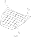
- the present invention provides a method for fabricating a photovoltaic module integrated into a vehicle body as shown in Figs. 12 , 13 and 14 .
- the vehicle body is divided into at least three components: a hood 8, a door 9, and a roof 10, and the above components can be fabricated by using the following fabricating method which includes the following steps:
- a mold is provided.
- the hood 8 is taken as an example.
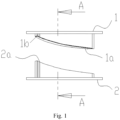
- the mold includes an upper mold 1 and lower mold 2, an upper surface of the upper mold 1 is a first molding surface 1a, a lower surface of the lower mold 2 is a second molding surface 2a.
- the first molding surface 1a and the second molding surface 2a are designed according to the hood 8.
- a protruded edge 1b is provided around the peripheral of the first molding surface 1a of the upper mold 1, so that when the upper mold 1 is mold clamped with the lower mold 2, there is a greater pressure on the protruded edge 1b, and a cavity is formed between the first molding surface 1a and the second molding surface 2a, which is convenient for vacuuming and cutting the edge material, and may form a weld wiring 7.
- the first thermoplastic material 3a is a transparent PC board, and the photovoltaic module 6 can absorb the sunlight.
- the second thermoplastic material 3b is an opaque carbon fiber reinforced PC board.
- the first thermoplastic material 3a and the second thermoplastic material 3b used for forming vehicle components which is pre-heating to soften, in which the heating temperature ranges from 100°C-240°C, and the preferable temperature is 160°C.
- the first thermoplastic material 3a and the second thermoplastic material 3b are heated by using electric heating tube 4.
- the upper mold 1 and the lower mold 2 are put into a blister machine, and the blister machine is convenient for lifting and lowing operations of the upper mold 1 and the lower mold 2 and is also convenient for vacuuming.
- the first thermoplastic material 3a and the second thermoplastic material 3b are moved to dispose between the upper mold 1 and the lower mold 2, and the peripheral of the first thermoplastic material 3a and the second thermoplastic material 3b are clamped to fix, so the upper mold 1 and the lower mold 3 can contact the first thermoplastic material 3a and the second thermoplastic material 3b. it should be illustrated to that the first thermoplastic material 3a and the second thermoplastic material 3b have a certain tension.
- the upper mold 1 is lowered, while the lower mold 2 is lifted, so that the first thermoplastic material 3a and the second thermoplastic material 3b are respectively attached to the second molding surface 2a of the lower mold 2 and the first molding surface 1a of the upper mold 1.
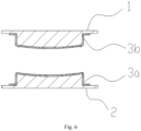
- a blister machine is necessary to vacuum and remove all the gap 5 between the first thermoplastic material 3a and the second thermoplastic material 3b and the lower mold 2 and the upper mold 1, so that the adhesion becomes closer.
- the pre-packaged photovoltaic module 6 is placed on the lower mold 2 after heating and softening, in which the heating temperature ranges from 40°C-150°C, and the preferable temperature is 140°C, and the material of the photovoltaic module 6 is one of TPE, TPU, TPO, TPSE, PVB, an ionic intermediate mold.
- the upper mold 1 and the lower mold 2 are driven to perform mold together under the operation of high temperature and high pressure.
- the temperature of each material is different, and the pressure ranges from 60-180 psi.
- the photovoltaic module 6 is encapsulated into the first thermoplastic material 3a and the second thermoplastic material 3b.
- the upper mold 1 and the lower mold 2 is molded together, and the first thermoplastic material 3a and the second thermoplastic material 3b forms a weld wiring 7 under the operation of high pressure of the edge 1b, so that the photovoltaic module 6 can encapsulate into the first thermoplastic material 3a and the second thermoplastic material 3b completely.
- thermoplastic material 3a and the second thermoplastic material 3b are cooled and shaped, the upper mold 1 and the lower mold 2 are separated to obtain a semi-finished product, and then the excess edge material is cut off to obtain the finished product, which is hood 8.
- the second thermoplastic material 3b in step S2 is replaced with a pre-stamped metal piece 3c, the fabricating step are as follows: S1': a mold is designed firstly. A hood 8 is taken as an example as shown in Fig. 15 . The mold includes an upper mold 1 and a lower mold 2, the edge of the upper mold 1 has an overflow groove 1c, and a lower surface of the lower mold 2 is second molding surface 2a.
- thermoplastic material 3a a piece of the first thermoplastic material 3a is pre-heated to soften.
- the pre-packaged photovoltaic module 6 is placed on the lower mold 2 after heating and softening.
- the upper mold 1 and the lower mold 2 are driven to mold under the operation of high temperature and high pressure, the heating temperature is shown as in Fig. 19 , which is distinguished by thermoplastic materials.
- the pressure ranges from 60-180 psi.
- the first thermoplastic material 3 reaches the overflow groove 1c of the upper mold 1 through the opening 3c' on the edge of the pre-stamped metal piece 3c due to extrusion.
- the structure of rivet 11 is formed, as shown in Fig. 18 .
- the photovoltaic module 6 is encapsulated into the first thermoplastic material 3a and the pre-stamped metal piece 3c.
- the door 9 and the roof 10 and other components are prepared according to the above two different embodiments to obtain finished parts.
- the door 9 and the roof 10 are different from other components only in the corresponding upper mold 1 and lower mold 2, and the other components are different.
- the steps are the same as above.
Landscapes
- Engineering & Computer Science (AREA)
- Mechanical Engineering (AREA)
- Chemical & Material Sciences (AREA)
- Combustion & Propulsion (AREA)
- Transportation (AREA)
- Architecture (AREA)
- Structural Engineering (AREA)
- Physics & Mathematics (AREA)
- Fluid Mechanics (AREA)
- Casting Or Compression Moulding Of Plastics Or The Like (AREA)
- Blow-Moulding Or Thermoforming Of Plastics Or The Like (AREA)
Abstract
Description
- The present invention relates to the technical field of photovoltaic technology, particularly relates to photovoltaic module and fabricating method thereof.
- Most of the general vehicle-mounted photovoltaics are installed on brackets or directly pasted photovoltaic modules on the roof or body of the vehicle such as is disclosed in
CN patent publication No. 201520898185.2 CN patent publication no. 202111594907.1 - The brackets or photovoltaic modules is arranged on the roof, or the vehicle body that will affect the appearance, the weight and the wind resistance also may be increased, which in turn will increase the fuel consumption or power consumption of the vehicle. The way of encapsulating photovoltaic cells with double-layer glass to make roof skylights or roofs can only be limited to the roof of vehicle. With the increasing popularity of electric vehicles, it is necessary to reduce the anxiety about the driving distance of electric vehicles, it is necessary to consider a larger available area to integrate photovoltaic power generation, such as hoods, doors, etc.
- The object of this invention is to provide a photovoltaic module that can be fully integrated into the vehicle body or vehicle shell without affecting the appearance, or the fuel consumption or power consumption of the vehicle is not increased due to the weight of the bracket and the increase in wind resistance, and the internal stress caused by the cooling of the battery sheet can be reduced to reduce the damage of the battery cells, the photovoltaic module is not easy to deform and can be applied to large sized vehicle body.
- In order to achieve the above object, the present invention provides a method for fabricating photovoltaic module integrated into the vehicle body. The vehicle body is divided into three components, which includes a hood, a door and a roof. The above components can be fabricated by using following fabricating method. The fabricating method includes the following steps:
- S1: first, the mold is provided. The mold includes an upper mold and a lower mold. The upper surface of the upper mold is a first molding surface, and the lower surface of the lower mold is a second molding surface.
- S2: secondly, the two pieces of the first thermoplastic material and the second thermoplastic material forming the components of the vehicle body are preheated to soften them.
- S3: the first thermoplastic material and the second thermoplastic material are moved to dispose between the upper mold and the lower mold, and the peripheral of the thermoplastic material and the second thermoplastic material are clamped to fix.
- S4: the upper mold is lowered, and the lower mold is lifted at the same time, so that the first thermoplastic material and the second thermoplastic material are attached to the second molding surface of the lower mold and the first molding surface of the upper mold respectively.
- S5: the pre-packaged photovoltaic module is placed on the lower mold after heating and softening.
- S6: the upper mold and the lower mold are driven to mold. The photovoltaic module is encapsulated into the first thermoplastic material and the second thermoplastic material under the operation of the high temperature and high pressure.
- S7: after the first thermoplastic material and the second thermoplastic material are cooled and shaped, the upper mold and the lower mold are separated to obtain a semi-finished product, and then the excess edge material is cut off to obtain the product of the hood.
- S8: the door and the roof of the vehicle are fabricated in the same way as above description to obtain the product of finished components.
- Preferably, a protruded edge is provided around the first molding surface of the upper mold.
- Preferably, a first thermoplastic material is a transparent PC board, and the second thermoplastic material is a transparent or opaque carbon fiber reinforced PC board.
- Preferably, in the step S2, the heating temperature of the first thermoplastic material and the second thermoplastic material ranges from 100°C-240°C.
- Preferably, in the step S4, the upper mold and the lower mold are performed with vacuum exhausted.
- Preferably, in the step S5, the photovoltaic module is heated to 40°C-150°C, and the pre-packaging material of the photovoltaic module is one of TPE, TPU, TPO, TPSE, PVB, and an ionic intermediate mold. The appropriate temperature depends on the type of packaging material and the curvature of the molding surface.
- Preferably, in the step S6, the upper mold and the lower mold are mold clamping, a weld wiring is formed by the first thermoplastic material and the second thermoplastic material under the operation of the high pressure at the edges.
- By adopting the above steps, the invention is not only a photovoltaic module, but also a part of the vehicle body and the vehicle shell, which can be completely integrated into the vehicle body. The available area on the vehicle can be used as its own power generation to reduce vehicle fuel consumption or power consumption. It is not easily deformed and can be applied to larger-sized vehicle bodies.
-
-
Fig. 1 is a schematic diagram showing an upper mold and the lower mold in accordance with this invention. -
Fig. 2 is A-A sectional view ofFig.1 in accordance with this invention. -
Fig. 3 is a schematic diagram of heating the first thermoplastic material and the second thermoplastic material. -
Fig. 4 is a schematic diagram of step S3. -
Fig. 5 is a schematic diagram of step S4. -
Fig, 6 is a schematic diagram of attachment after vacuuming. -
Fig. 7 is a schematic diagram of step S5. -
Fig. 8 is a schematic diagram of step S6. -
Fig. 9 is an enlarged view of component I inFig. 8 . -
Fig. 10 is a schematic diagram of step S7. -
Fig. 11 is a schematic diagram of the finished vehicle hood. -
Fig. 12 is a three-dimensional view of the finished vehicle hood. -
Fig. 13 is a perspective view of the door component. -
Fig. 14 is a schematic diagram of the vehicle roof component. -
Fig. 15 shows a schematic diagram of the upper mold and the lower mold inembodiment 2. -
Fig. 16 is a schematic diagram of step s3' inembodiment 2. -
Fig. 17 is a schematic diagram of step s4' inembodiment 2. -
Fig. 18 is a schematic diagram of the finished vehicle hood inembodiment 2. -
Fig. 19 shows the different molding temperature for various thermoplastic materials. - The present invention will be further described in detail below with reference to the embodiments given in the accompanying drawings.
- First embodiment: The present invention provides a method for fabricating a photovoltaic module integrated into a vehicle body as shown in
Figs. 12 ,13 and 14 . The vehicle body is divided into at least three components: ahood 8, adoor 9, and aroof 10, and the above components can be fabricated by using the following fabricating method which includes the following steps: - As in
Fig. 1 andFig. 2 , a mold is provided. Thehood 8 is taken as an example. The mold includes anupper mold 1 andlower mold 2, an upper surface of theupper mold 1 is afirst molding surface 1a, a lower surface of thelower mold 2 is a second molding surface 2a. Thefirst molding surface 1a and the second molding surface 2a are designed according to thehood 8. Aprotruded edge 1b is provided around the peripheral of thefirst molding surface 1a of theupper mold 1, so that when theupper mold 1 is mold clamped with thelower mold 2, there is a greater pressure on theprotruded edge 1b, and a cavity is formed between thefirst molding surface 1a and the second molding surface 2a, which is convenient for vacuuming and cutting the edge material, and may form a weld wiring 7. - As shown in
Fig. 3 , in this embodiment, the first thermoplastic material 3a is a transparent PC board, and thephotovoltaic module 6 can absorb the sunlight. The secondthermoplastic material 3b is an opaque carbon fiber reinforced PC board. The first thermoplastic material 3a and the secondthermoplastic material 3b used for forming vehicle components which is pre-heating to soften, in which the heating temperature ranges from 100°C-240°C, and the preferable temperature is 160°C. In this embodiment, the first thermoplastic material 3a and the secondthermoplastic material 3b are heated by usingelectric heating tube 4. - As shown in
Fig. 4 , theupper mold 1 and thelower mold 2 are put into a blister machine, and the blister machine is convenient for lifting and lowing operations of theupper mold 1 and thelower mold 2 and is also convenient for vacuuming. The first thermoplastic material 3a and the secondthermoplastic material 3b are moved to dispose between theupper mold 1 and thelower mold 2, and the peripheral of the first thermoplastic material 3a and the secondthermoplastic material 3b are clamped to fix, so theupper mold 1 and the lower mold 3 can contact the first thermoplastic material 3a and the secondthermoplastic material 3b. it should be illustrated to that the first thermoplastic material 3a and the secondthermoplastic material 3b have a certain tension. - As shown in
Fig. 5 andFig. 6 , theupper mold 1 is lowered, while thelower mold 2 is lifted, so that the first thermoplastic material 3a and the secondthermoplastic material 3b are respectively attached to the second molding surface 2a of thelower mold 2 and thefirst molding surface 1a of theupper mold 1. In order to adhere more closely, a blister machine is necessary to vacuum and remove all thegap 5 between the first thermoplastic material 3a and the secondthermoplastic material 3b and thelower mold 2 and theupper mold 1, so that the adhesion becomes closer. - As shown in
Fig. 7 , the pre-packagedphotovoltaic module 6 is placed on thelower mold 2 after heating and softening, in which the heating temperature ranges from 40°C-150°C, and the preferable temperature is 140°C, and the material of thephotovoltaic module 6 is one of TPE, TPU, TPO, TPSE, PVB, an ionic intermediate mold. - As shown in
Fig. 8 , theupper mold 1 and thelower mold 2 are driven to perform mold together under the operation of high temperature and high pressure. Please refer toFig. 19 , the temperature of each material is different, and the pressure ranges from 60-180 psi. Thephotovoltaic module 6 is encapsulated into the first thermoplastic material 3a and the secondthermoplastic material 3b. As shown inFig. 9 , theupper mold 1 and thelower mold 2 is molded together, and the first thermoplastic material 3a and the secondthermoplastic material 3b forms a weld wiring 7 under the operation of high pressure of theedge 1b, so that thephotovoltaic module 6 can encapsulate into the first thermoplastic material 3a and the secondthermoplastic material 3b completely. - As shown in
Fig. 10 , after the first thermoplastic material 3a and the secondthermoplastic material 3b are cooled and shaped, theupper mold 1 and thelower mold 2 are separated to obtain a semi-finished product, and then the excess edge material is cut off to obtain the finished product, which ishood 8. - Second Embodiment: In this embodiment, the second
thermoplastic material 3b in step S2 is replaced with apre-stamped metal piece 3c, the fabricating step are as follows: S1': a mold is designed firstly. Ahood 8 is taken as an example as shown inFig. 15 . The mold includes anupper mold 1 and alower mold 2, the edge of theupper mold 1 has anoverflow groove 1c, and a lower surface of thelower mold 2 is second molding surface 2a. - S2': a piece of the first thermoplastic material 3a is pre-heated to soften.
- S3': the
pre-stamped metal piece 3c is moved to theupper mold 1, where the opening 3c' on the edge of thepre-stamped metal piece 3c overlaps theoverflow groove 1c of theupper mold 1. The first thermoplastic material 3a is moved to dispose between theupper mold 1 and thelower mold 2, and the peripheral of the first thermoplastic material 3a is clamped to fix. - S4': the
lower mold 2 is lifted, so the first thermoplastic material 3s is attached to the second molding surface 2a of thelower mold 2 and then a vacuuming is performed as shown inFig. 17 . - S5': the pre-packaged
photovoltaic module 6 is placed on thelower mold 2 after heating and softening. Theupper mold 1 and thelower mold 2 are driven to mold under the operation of high temperature and high pressure, the heating temperature is shown as inFig. 19 , which is distinguished by thermoplastic materials. The pressure ranges from 60-180 psi. The first thermoplastic material 3 reaches theoverflow groove 1c of theupper mold 1 through the opening 3c' on the edge of thepre-stamped metal piece 3c due to extrusion. After cooling, the structure of rivet 11 is formed, as shown inFig. 18 . Next, thephotovoltaic module 6 is encapsulated into the first thermoplastic material 3a and thepre-stamped metal piece 3c. - S6': after the first thermoplastic material 3a is cooled and shaped, the
upper mold 1 andlower mold 2 is separated to obtain the semi-finished product, as shown inFig. 18 . Then, the excess edge material to obtain the finished product, which ishood 8. - The
door 9 and theroof 10 and other components are prepared according to the above two different embodiments to obtain finished parts. Thedoor 9 and theroof 10 are different from other components only in the correspondingupper mold 1 andlower mold 2, and the other components are different. The steps are the same as above. - While the invention has been described in terms of what is presently considered to be the most practical and preferred embodiments, it is to be understood that the invention needs not be limited to the disclosed embodiments. On the contrary, it is intended to cover various modifications and similar arrangements included within the spirit and scope of the appended claims which are to be accorded with the broadest interpretation, so as to encompass all such modifications and similar structures.
Claims (7)
- A method for fabricating photovoltaic module integrated into a vehicle body, the vehicle body is divided into a plurality of components, a hood (8), a door (9) and a roof (10), the plurality of components is prepared by using following fabricating method, the characterized is in that the fabricating method comprises the steps:S1: first to design the mold, taking the hood (8) as an example, the mold includes an upper mold (1) and a lower mold (2), an upper surface of the upper mold (1) is a first molding surface (1a) and a lower surface of the lower mold (2) is a second molding surface (2a);S2: pre-heating a first thermoplastic material (3a) and a second thermoplastic material (3b) to soften;S3: moving the first thermoplastic material (3a) and the second thermoplastic material (3b) to dispose between the upper mold (1) and lower mold (2), and clamping to fix the peripheral of the first thermoplastic material (3a) and the second thermoplastic material (3b);S4: lowering the upper mold (1) and lifting the lower mold (2) to let the first thermoplastic material (3a) and the second thermoplastic material (3b) to attach the second molding surface (2a) of the lower mold (2) and the first molding surface (1a) of the upper mold (1) respectively;S5: placing a pre-packaging photovoltaic module (6) on the lower mold (2) after heating and softening;S6: performing a molding process with driving the upper mold (1) and the lower mold (2) so as to the photovoltaic module (6) is disposed between the first thermoplastic material (3a) and the second thermoplastic material (3b);S7: separating the upper mold (1) and the lower mold (2) after the first thermoplastic material (3a) and the second thermoplastic material (3b) cooled and shaped to obtain a semi-finished product, and subsequently, the excess edge material is cut off to obtain the hood (8); andS8: fabricating the door (9) and the roof (10) in the same manner as above to obtain finished components.
- The method for fabricating photovoltaic module integrated into a vehicle body according to claim 1, wherein a protruded edge (1b) is provided around the peripheral of the first molding surface (1a) of the upper mold (1).
- The method for fabricating photovoltaic module integrated into a vehicle body according to claim 1, wherein the first thermoplastic material (3a) is a transparent PC board, and the second thermoplastic material (3b) is a transparent carbon fiber reinforced PC board or an opaque carbon fiber reinforced PC board.
- The method for fabricating photovoltaic module integrated into a vehicle body according to claim 1, wherein the heating temperature of heating the first thermoplastic material (3a) and the second thermoplastic material (3b) ranges from 100°C-240°C.
- The method for fabricating photovoltaic module integrated into a vehicle body according to claim 1, further comprising a vacuum exhausting is performed to the upper mold (1) and the lower mold (2).
- The method for fabricating photovoltaic module integrated into a vehicle body according to claim 1, wherein a temperature of photovoltaic module (6) is heated to 40°C-150°C, and the pre-packaging material of the photovoltaic module (6) is TPE, TPU, TPO, TPSE, PVB or ionic intermediate mold.
- The method for fabricating photovoltaic module integrated into a vehicle body according to claim 1, wherein a weld wiring (7) is formed by the first thermoplastic material (3a) and the second thermoplastic material (3b) under the operation of the high pressure at the edges (1b) in step S6.
Applications Claiming Priority (2)
| Application Number | Priority Date | Filing Date | Title |
|---|---|---|---|
| CN202210552659.2A CN115122554A (en) | 2022-05-19 | 2022-05-19 | Method for preparing photovoltaic module integrated with vehicle body |
| PCT/CN2023/094102 WO2023221905A1 (en) | 2022-05-19 | 2023-05-15 | Method for preparing photovoltaic module integrated with vehicle body |
Publications (2)
| Publication Number | Publication Date |
|---|---|
| EP4527587A1 true EP4527587A1 (en) | 2025-03-26 |
| EP4527587A4 EP4527587A4 (en) | 2026-05-13 |
Family
ID=83376675
Family Applications (1)
| Application Number | Title | Priority Date | Filing Date |
|---|---|---|---|
| EP23806857.1A Pending EP4527587A4 (en) | 2022-05-19 | 2023-05-15 | METHOD FOR MANUFACTURING A PHOTOVOLTAIC MODULE INTEGRATED INTO THE VEHICLE BODY |
Country Status (4)
| Country | Link |
|---|---|
| US (1) | US20250091281A1 (en) |
| EP (1) | EP4527587A4 (en) |
| CN (1) | CN115122554A (en) |
| WO (1) | WO2023221905A1 (en) |
Families Citing this family (1)
| Publication number | Priority date | Publication date | Assignee | Title |
|---|---|---|---|---|
| CN115122554A (en) * | 2022-05-19 | 2022-09-30 | 沃沛斯(常州)能源科技有限公司 | Method for preparing photovoltaic module integrated with vehicle body |
Family Cites Families (22)
| Publication number | Priority date | Publication date | Assignee | Title |
|---|---|---|---|---|
| US4067764A (en) * | 1977-03-15 | 1978-01-10 | Sierracin Corporation | Method of manufacture of solar cell panel |
| US6121542A (en) * | 1996-05-17 | 2000-09-19 | Canon Kabushiki Kaisha | Photovoltaic device |
| JP5405005B2 (en) * | 2007-05-02 | 2014-02-05 | 三洋電機株式会社 | Manufacturing method of solar cell module |
| US20090188603A1 (en) * | 2008-01-25 | 2009-07-30 | Applied Materials, Inc. | Method and apparatus for controlling laminator temperature on a solar cell |
| TW201101518A (en) * | 2009-06-19 | 2011-01-01 | Te-Li Hu | Re-sizable and re-connectable solar panel and lamination technique |
| WO2011036802A1 (en) * | 2009-09-28 | 2011-03-31 | トヨタ自動車株式会社 | Solar cell module manufacturing method and precursor for solar cell module |
| US20110159271A1 (en) * | 2009-12-30 | 2011-06-30 | Du Pont Apollo Ltd. | Foam gasket for the protection of photovoltaic modules and method of preparing the same |
| DE102010015740B4 (en) * | 2010-04-21 | 2013-04-11 | Mühlbauer Ag | Device for producing a solar module with flexible thin-film solar cells |
| US9112080B1 (en) * | 2011-03-11 | 2015-08-18 | Apollo Precision (Kunming) Yuanhong Limited | Electrical connectors of building integrable photovoltaic modules |
| KR101259794B1 (en) * | 2011-07-13 | 2013-04-30 | 엘지전자 주식회사 | Method and apparatus for manufacturing solar cell module |
| CN105810776B (en) * | 2014-12-31 | 2018-06-29 | 北京创昱科技有限公司 | A kind of preparation method of carbon fiber solar panels and its carbon fiber solar panels |
| JP6426480B2 (en) * | 2015-01-13 | 2018-11-21 | トヨタ自動車株式会社 | Seal structure of solar roof end |
| CN105128943B (en) * | 2015-09-09 | 2018-02-16 | 宁波山迪光能技术有限公司 | The solar energy roof of makrolon encapsulation or skylight and preparation method thereof |
| CN205440235U (en) * | 2015-11-25 | 2016-08-10 | 卢立 | Adjustable in -car temperature's motor vehicle |
| EP3597389A1 (en) * | 2018-07-18 | 2020-01-22 | PARAT Beteiligungs GmbH | Flat element with integrated solar cells and method for producing a flat element with integrated solar cells |
| CN108831944A (en) * | 2018-08-20 | 2018-11-16 | 汉能移动能源控股集团有限公司 | Solar vehicle component, method of making same, and vehicle |
| CN109624724B (en) * | 2019-01-15 | 2020-09-01 | 武汉理工大学 | A carbon fiber automobile hood for solar power generation and preparation method thereof |
| JP7413097B2 (en) * | 2019-03-25 | 2024-01-15 | フタムラ化学株式会社 | Method for producing a thin plate-like laminate having a film-like resin layer |
| DE102019127108A1 (en) * | 2019-10-09 | 2021-04-15 | Leonhard Kurz Stiftung & Co. Kg | Method and device for producing a plastic component and a plastic component |
| CN111590796A (en) * | 2020-04-30 | 2020-08-28 | 福建闽维科技有限公司 | Forming die of thermoplastic composite material and using method thereof |
| CN112397601B (en) * | 2020-10-15 | 2022-06-21 | 浙江美尚光伏有限公司 | Solar cell module and production process thereof |
| CN115122554A (en) * | 2022-05-19 | 2022-09-30 | 沃沛斯(常州)能源科技有限公司 | Method for preparing photovoltaic module integrated with vehicle body |
-
2022
- 2022-05-19 CN CN202210552659.2A patent/CN115122554A/en active Pending
-
2023
- 2023-05-15 EP EP23806857.1A patent/EP4527587A4/en active Pending
- 2023-05-15 WO PCT/CN2023/094102 patent/WO2023221905A1/en not_active Ceased
- 2023-05-15 US US18/867,297 patent/US20250091281A1/en active Pending
Also Published As
| Publication number | Publication date |
|---|---|
| US20250091281A1 (en) | 2025-03-20 |
| CN115122554A (en) | 2022-09-30 |
| WO2023221905A1 (en) | 2023-11-23 |
| EP4527587A4 (en) | 2026-05-13 |
Similar Documents
| Publication | Publication Date | Title |
|---|---|---|
| DE60335399D1 (en) | METHOD OF MANUFACTURING SOLAR BATTERY MODULES | |
| EP2775536B1 (en) | Solar panel and method for manufacturing the same | |
| US20030005954A1 (en) | Solar cell module and method of manufacturing the same | |
| US20250091281A1 (en) | Method for preparing photovoltaic module integrated with vehicle body | |
| CN111132891A (en) | Body part and method for manufacturing body part | |
| CN102186718A (en) | Vehicle surface component having a solar cell arrangement | |
| CN100361318C (en) | Solar energy battery skylight and its manufacturing method | |
| EP3070749B1 (en) | Solar panel | |
| JPH03204979A (en) | Solar cell module and manufacture thereof | |
| EP2760052B1 (en) | A fabrication method for solar cell assembly | |
| CN114006116A (en) | Thermoplastic composite sandwich battery box tray and manufacturing method thereof | |
| CN112248479A (en) | Production process of spare plate of automobile trunk | |
| KR102771733B1 (en) | Connection Plate-Integrated Solar Cell Module And Laminating Method For Solar Cell Module | |
| CN105128943B (en) | The solar energy roof of makrolon encapsulation or skylight and preparation method thereof | |
| CN2850998Y (en) | Solar cell louver | |
| CN116441381A (en) | Stamping method and system for outer plate part of roof top cover of automotive glass awning | |
| CN115763598B (en) | Curved solar glass, manufacturing method and vehicle comprising curved solar glass | |
| JP3785263B2 (en) | Solar cell module and manufacturing method thereof | |
| CN212907897U (en) | A mounting bracket and battery module | |
| EP2474043B1 (en) | Solar battery assembly and method for forming the same | |
| CN119032429A (en) | Curved laminated solar panel and method of manufacturing the same | |
| CN210149428U (en) | Automobile top cover and automobile | |
| CN205113458U (en) | Solar car top and skylight of polycarbonate encapsulation | |
| CN223467103U (en) | Solar automobile exterior trimming part structure | |
| CN220065715U (en) | Novel packaging structure of component and component |
Legal Events
| Date | Code | Title | Description |
|---|---|---|---|
| STAA | Information on the status of an ep patent application or granted ep patent |
Free format text: STATUS: THE INTERNATIONAL PUBLICATION HAS BEEN MADE |
|
| PUAI | Public reference made under article 153(3) epc to a published international application that has entered the european phase |
Free format text: ORIGINAL CODE: 0009012 |
|
| STAA | Information on the status of an ep patent application or granted ep patent |
Free format text: STATUS: REQUEST FOR EXAMINATION WAS MADE |
|
| 17P | Request for examination filed |
Effective date: 20241111 |
|
| AK | Designated contracting states |
Kind code of ref document: A1 Designated state(s): AL AT BE BG CH CY CZ DE DK EE ES FI FR GB GR HR HU IE IS IT LI LT LU LV MC ME MK MT NL NO PL PT RO RS SE SI SK SM TR |
|
| DAV | Request for validation of the european patent (deleted) | ||
| DAX | Request for extension of the european patent (deleted) | ||
| A4 | Supplementary search report drawn up and despatched |
Effective date: 20260413 |
|
| RIC1 | Information provided on ipc code assigned before grant |
Ipc: B29C 43/18 20060101AFI20260407BHEP Ipc: B29C 43/36 20060101ALI20260407BHEP Ipc: B29C 51/08 20060101ALI20260407BHEP Ipc: B32B 37/10 20060101ALI20260407BHEP Ipc: B60K 16/00 20200101ALI20260407BHEP Ipc: B62D 29/04 20060101ALI20260407BHEP Ipc: H10F 19/80 20250101ALI20260407BHEP Ipc: B29C 51/14 20060101ALN20260407BHEP Ipc: B29C 43/20 20060101ALN20260407BHEP |