EP4527521A1 - Steel continuous casting method - Google Patents
Steel continuous casting method Download PDFInfo
- Publication number
- EP4527521A1 EP4527521A1 EP23830817.5A EP23830817A EP4527521A1 EP 4527521 A1 EP4527521 A1 EP 4527521A1 EP 23830817 A EP23830817 A EP 23830817A EP 4527521 A1 EP4527521 A1 EP 4527521A1
- Authority
- EP
- European Patent Office
- Prior art keywords
- casting
- rolling reduction
- cast piece
- speed
- continuous casting
- Prior art date
- Legal status (The legal status is an assumption and is not a legal conclusion. Google has not performed a legal analysis and makes no representation as to the accuracy of the status listed.)
- Pending
Links
Images


Classifications
-
- B—PERFORMING OPERATIONS; TRANSPORTING
- B22—CASTING; POWDER METALLURGY
- B22D—CASTING OF METALS; CASTING OF OTHER SUBSTANCES BY THE SAME PROCESSES OR DEVICES
- B22D11/00—Continuous casting of metals, i.e. casting in indefinite lengths
- B22D11/12—Accessories for subsequent treating or working cast stock in situ
- B22D11/128—Accessories for subsequent treating or working cast stock in situ for removing
-
- B—PERFORMING OPERATIONS; TRANSPORTING
- B22—CASTING; POWDER METALLURGY
- B22D—CASTING OF METALS; CASTING OF OTHER SUBSTANCES BY THE SAME PROCESSES OR DEVICES
- B22D11/00—Continuous casting of metals, i.e. casting in indefinite lengths
- B22D11/12—Accessories for subsequent treating or working cast stock in situ
- B22D11/1206—Accessories for subsequent treating or working cast stock in situ for plastic shaping of strands
-
- B—PERFORMING OPERATIONS; TRANSPORTING
- B21—MECHANICAL METAL-WORKING WITHOUT ESSENTIALLY REMOVING MATERIAL; PUNCHING METAL
- B21B—ROLLING OF METAL
- B21B1/00—Metal-rolling methods or mills for making semi-finished products of solid or profiled cross-section; Sequence of operations in milling trains; Layout of rolling-mill plant, e.g. grouping of stands; Succession of passes or of sectional pass alternations
- B21B1/46—Metal-rolling methods or mills for making semi-finished products of solid or profiled cross-section; Sequence of operations in milling trains; Layout of rolling-mill plant, e.g. grouping of stands; Succession of passes or of sectional pass alternations for rolling metal immediately subsequent to continuous casting
-
- B—PERFORMING OPERATIONS; TRANSPORTING
- B22—CASTING; POWDER METALLURGY
- B22D—CASTING OF METALS; CASTING OF OTHER SUBSTANCES BY THE SAME PROCESSES OR DEVICES
- B22D11/00—Continuous casting of metals, i.e. casting in indefinite lengths
- B22D11/10—Supplying or treating molten metal
-
- B—PERFORMING OPERATIONS; TRANSPORTING
- B22—CASTING; POWDER METALLURGY
- B22D—CASTING OF METALS; CASTING OF OTHER SUBSTANCES BY THE SAME PROCESSES OR DEVICES
- B22D11/00—Continuous casting of metals, i.e. casting in indefinite lengths
- B22D11/12—Accessories for subsequent treating or working cast stock in situ
- B22D11/128—Accessories for subsequent treating or working cast stock in situ for removing
- B22D11/1282—Vertical casting and curving the cast stock to the horizontal
-
- B—PERFORMING OPERATIONS; TRANSPORTING
- B22—CASTING; POWDER METALLURGY
- B22D—CASTING OF METALS; CASTING OF OTHER SUBSTANCES BY THE SAME PROCESSES OR DEVICES
- B22D11/00—Continuous casting of metals, i.e. casting in indefinite lengths
- B22D11/12—Accessories for subsequent treating or working cast stock in situ
- B22D11/128—Accessories for subsequent treating or working cast stock in situ for removing
- B22D11/1287—Rolls; Lubricating, cooling or heating rolls while in use
-
- B—PERFORMING OPERATIONS; TRANSPORTING
- B22—CASTING; POWDER METALLURGY
- B22D—CASTING OF METALS; CASTING OF OTHER SUBSTANCES BY THE SAME PROCESSES OR DEVICES
- B22D11/00—Continuous casting of metals, i.e. casting in indefinite lengths
- B22D11/16—Controlling or regulating processes or operations
-
- B—PERFORMING OPERATIONS; TRANSPORTING
- B22—CASTING; POWDER METALLURGY
- B22D—CASTING OF METALS; CASTING OF OTHER SUBSTANCES BY THE SAME PROCESSES OR DEVICES
- B22D11/00—Continuous casting of metals, i.e. casting in indefinite lengths
- B22D11/16—Controlling or regulating processes or operations
- B22D11/18—Controlling or regulating processes or operations for pouring
-
- B—PERFORMING OPERATIONS; TRANSPORTING
- B22—CASTING; POWDER METALLURGY
- B22D—CASTING OF METALS; CASTING OF OTHER SUBSTANCES BY THE SAME PROCESSES OR DEVICES
- B22D11/00—Continuous casting of metals, i.e. casting in indefinite lengths
- B22D11/16—Controlling or regulating processes or operations
- B22D11/20—Controlling or regulating processes or operations for removing cast stock
Definitions
- the present invention relates to a steel continuous casting method.
- solidification shrinkage causes suction flow of an unsolidified molten steel (called "unsolidified layer") in the withdrawal direction of a cast piece.
- the unsolidified layer contains concentrated solute elements such as carbon (C), phosphorus (P), sulfur (S), and manganese (Mn). If the concentrated molten steel flows to the center of a cast piece and is solidified, what is called center segregation is caused.
- Factors causing a concentrated molten steel to flow in the late solidification stage include, in addition to the above solidification shrinkage, cast piece bulging between rolls due to molten steel static pressure and roll misalignment of cast piece support rolls.
- the center segregation decreases the quality of a steel product, especially, a steel plate.
- a steel product especially, a steel plate.
- sour gas causes hydrogen-induced cracking from a center segregation as the starting point.
- Similar problems arise also in marine structures, storage tanks, petroleum tanks, or the like.
- recent steel materials are often required to be used in harsh environments such as lower temperature environments or more corrosive environments, and this has increased the importance of reducing the center segregation of cast pieces.
- a late solidification-stage soft reduction method in which a continuous cast piece having an unsolidified layer therein is subjected to rolling reduction in a continuous casting machine is known to be specifically effective in improving center segregation.
- the "late solidification-stage soft reduction method” is a method in which rolling reduction rolls are placed near the solidification completion position of a cast piece, and the rolling reduction rolls are used to subject a cast piece during continuous casting to gradual rolling reduction at a rolling reduction speed corresponding to the solidification shrinkage amount.
- rolling reduction with rolling reduction rolls prevents voids from generating at the center of a cast piece or a concentrated molten steel from flowing, and this suppresses the center segregation of the cast piece.
- PTL 1 discloses that in a continuous casting method of applying soft reduction to the late-stage solidification portion of a continuous cast piece, the rolling reduction amount per unit time of a cast piece in the section where soft reduction is applied is defined from the surface temperature of the cast piece at the start of the rolling reduction and from the thickness of the unsolidified layer of the cast piece at the rolling reduction position.
- PTL 1 focuses on the thickness of the unsolidified layer of a cast piece as an index for effective soft reduction. According to PTL 1, this is based on the finding that the rolling reduction amount set for rolling reduction rolls is transmitted to the solid-liquid interface of a cast piece at a smaller rate (hereinafter called "rolling reduction efficiency") toward the casting downstream side or when the unsolidified layer of the cast piece has a smaller thickness.
- PTL 2 and PTL 3 each disclose a continuous casting method in which the rolling reduction speed of a cast piece is set to be larger toward the downstream side in the casting direction where the center of the cast piece in the thickness direction has a larger solid phase ratio.
- continuous casting is performed while rolling reduction is applied with multiple pairs of rolls in a region from the temperature at which the center of a bloom cast piece in the thickness direction has a solid phase ratio of 0.1 to 0.3 to the temperature corresponding to the flow-limit solid phase ratio.
- PTL 4 discloses a continuous casting method of performing continuous casting while a rolling reduction force is applied to a cast piece being drawn.
- rolling reduction conditions are set or adjusted on the basis of information on a cross-sectional shape perpendicular to the longitudinal direction of the cast piece and information on the unsolidified portion shape on the cross section.
- PTL 5 discloses that at the completion of casting with a continuous casting machine, casting is completed while a normal casting speed is maintained without deceleration or stop of casting and without treatment of a bottom portion as the last end portion of a cast piece.
- PTL 5 is characterized in that a crater end at the last end of a cast piece is so controlled as to be positioned in a predetermined section, and a portion near the crater end is subjected to soft reduction with small diameter rolls provided in the section.
- the period from the casting completion until a cast piece is drawn from the inside of a continuous casting machine is called a period after the casting completion, and the period when a molten steel is continuously supplied to a mold to perform continuous casting at a stable casting speed is called an ordinary period.
- PTLs 1 to 4 did not disclose soft reduction conditions for a cast piece remaining in a machine after the casting completion, and thus in the casting methods disclosed in PTLs 1 to 4, it has been difficult to set appropriate rolling reduction conditions in the period after the casting completion.
- the quality of the bottom portion is improved, but in the period after the casting completion, soft reduction is not applied in conditions equivalent to those in the ordinary period.
- the quality of a cast piece cast in the period after the casting completion may deteriorate as compared to a cast piece cast in the ordinary period.
- the present invention has been completed in consideration of the above problems and is intended to provide a steel continuous casting method capable of improving the quality of a cast piece cast in the period after the casting completion.
- a steel continuous casting method capable of improving the quality of a cast piece cast in the period after the casting completion is provided.
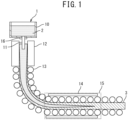
- FIG. 1 is a schematic view illustrating a continuous casting machine 1 to which a continuous casting method pertaining to an embodiment of the present invention is applied.
- the continuous casting machine 1 is a slab continuous casting machine and is, as an example, a vertical bending continuous casting machine.
- the continuous casting machine 1 may be a curved bending slab continuous casting machine.
- the longitudinal direction of a cast piece 3 and the moving direction of the cast piece 3 in the continuous casting machine 1 is called a casting direction
- the short direction of the rectangle on a cross section (a section orthogonal to the longitudinal direction) of the cast piece 3 (the direction orthogonal to the casting direction in a cross section of the cast piece 3 in FIG. 1 ) is called a thickness direction.
- the longitudinal direction of the rectangle on a cross section of the cast piece 3 (the front-to-rear direction in FIG. 1 ) is called a width direction.
- the dimension of the cast piece 3 in the thickness direction is called thickness, and the dimension in the width direction is called width.
- the continuous casting machine 1 includes a tundish 10 for pouring a molten steel 2 from a molten-steel ladle, a copper mold 12 for primarily cooling the molten steel 2 poured from the tundish 10 through an immersion nozzle 11, and multiple pairs of cast piece support rolls 13 for conveying a semi-solidified cast piece 3 drawn from the mold 12.
- the cast piece support rolls 13 include support rolls, guide rolls, and driving rolls arranged in sequence below the mold 12. Between the cast piece support rolls 13 adjacent in the casting direction, spray nozzles such as water spray nozzles and air mist spray nozzles (not illustrated) are arranged, and a secondary cooling zone is provided from just below the mold to the cast piece support rolls 13 at the end of the machine. While being drawn, a cast piece 3 is cooled with a secondary cooling water sprayed from the spray nozzles in the secondary cooling zone.
- spray nozzles such as water spray nozzles and air mist spray nozzles
- the continuous casting machine 1 also includes a plurality of segments in which multiple pairs of cast piece support rolls 13 are arranged. Of the plurality of segments, the segment in a soft reduction zone 15 is called a soft reduction segment 14.
- the soft reduction zone 15 is a region (cast piece support rolls 13) in which a cast piece 3 in the late solidification stage is subjected to rolling reduction in the casting direction of the continuous casting machine 1 and is a region in which the solid phase ratio at the thickness center of a cast piece 3, or the center solid phase ratio, is at least not less than 0.2 and less than 1.0.
- the thickness center of a cast piece 3 means the center in the thickness direction at a position in the width direction where the solid phase ratio of a thickness center portion in a cross section of the cast piece 3 is lowest.
- FIG. 2 and FIG. 3 are schematic views illustrating the soft reduction segment 14.
- a single soft reduction segment 14 may be provided or a plurality of soft reduction segments 14 may be provided.
- an example including a single soft reduction segment 14 will be described.
- FIG. 1 only the soft reduction segment 14 is illustrated as the segment, but segments other than the soft reduction zone 15 are provided.
- the soft reduction segment 14 includes six pairs of cast piece support rolls 13 arranged in the casting direction. Of the six pairs of cast piece support rolls 13, a pair of rolls that are rotary driven while applying a pressing force to a cast piece 3 in the thickness direction to draw out the cast piece 3 are called driving rolls 140, and other rolls that rotate in response to a ferrostatic pressure are called guide rolls 141.
- the driving rolls 140 may be provided at any position in the casting direction in the soft reduction segment 14, and multiple pairs of driving rolls may be provided in the soft reduction segment 14.
- the soft reduction segment 14 includes an upper frame 142, a lower frame 143, upstream struts 144, and downstream struts 145.
- the upper frame 142 and the lower frame 143 are provided to face each other in the thickness direction while a cast piece 3 being cast is interposed therebetween and are connected by the upstream struts 144 and the downstream struts 145.
- a plurality of cast piece support rolls 13 are rotatably fixed through bearings 146.
- the upstream struts 144 and the downstream struts 145 are capable of expansion and contraction by means of hydraulic pressure or the like and are expanded or contracted to adjust the distance between the upper frame 142 and the lower frame 143. Accordingly, the roll gap that is the distance in the thickness direction between pairs of cast piece support rolls 13 facing each other in the thickness direction is adjusted.
- the continuous casting machine 1 is used to perform steel continuous casting.
- the period in which casting is performed while a molten steel 2 is continuously supplied to the mold 12 is called an ordinary period, and the period after the casting completion is called a casting completion period.
- the casting completion is when the supply of a molten steel 2 to a mold 12 is completed.
- the casting completion is when pouring the molten steel 2 in a ladle into the tundish 10 is completed and pouring the molten steel 2 remaining in the tundish 10 into the mold 12 is completed or is when a sliding nozzle 16 connected the immersion nozzle 11 is finally closed.
- a cast piece 3 is preferably subjected to soft reduction in the soft reduction zone 15.
- the roll opening degree may be increased, and the long side faces of the cast piece 3 may be intentionally subjected to bulging by a molten steel static pressure.
- the intentional bulging is preferably started when the center portion of the cast piece 3 has a solid phase ratio of 0 and is preferably completed when the long side faces of the cast piece 3 have a total bulging amount of 3 mm or more and 10 mm or less.
- the cast piece 3 is preferably subjected to rolling reduction at a rolling reduction speed U of 0.3 mm/min or more and 2.0 mm/min or less when having a center solid phase ratio of at least not less than 0.2 and less than 1.0. If a cast piece having a center solid phase ratio within the above range is subjected to soft reduction at a rolling reduction speed U of less than 0.3 mm/min, V segregation highly probably occurs. If a cast piece having a center solid phase ratio within the above range is subjected to soft reduction at a rolling reduction speed U of more than 2.0 mm/min, reverse V segregation highly probably occurs.
- the casting speed V is decreased after the casting completion, and a low casting speed is maintained for a predetermined period of time. Accordingly, the top portion of the cast piece 3 (the last end portion of the cast piece 3) is cooled and solidified for head solidification.
- the head solidification is a process of solidifying the top portion of a cast piece 3 by feeding a cold charge to the molten steel 2 remaining in the mold 12 after the completion of casting because the molten steel 2 leaks out of the top portion when the top portion of the cast piece 3 drawn out of the mold 12 is unsolidified.
- the casting speed is typically decreased to certainly solidify the top portion.
- the casting speed V (m/min) is increased, and the cast piece 3 in the machine is drawn out.
- the casting speed V decreases when the elapsed time t is 0 or more and less than t 1 (time period T a ) where t is the elapsed time from the casting completion.
- the casting speed (drawing speed) V of the cast piece 3 before the casting completion is a first casting speed V a (m/min), and the casting speed V of the cast piece 3 changes to a second casting speed V 0 (m/min) that is the casting speed (drawing speed) for head solidification.
- the second casting speed V 0 is the casting speed required for head solidification and is appropriately set according to the specification of a continuous casting machine 1.
- the casting speed V is constant at the second casting speed V 0 , and head solidification is performed.
- the casting speed V increases.
- the casting speed V of the cast piece 3 changes from the second casting speed V 0 to a third casting speed V b (m/min) that is the casting speed for redrawing after the casting completion.
- Redrawing means that a cast piece 3 is redrawn by increasing the drawing speed after the completion of head solidification.
- the cast piece 3 is drawn at the third casting speed V b until the drawing is completed.
- the period of time T a is also called a deceleration step
- the period of time T 0 is also called a head solidification step
- the period of time T b is also called an acceleration step
- the period after the time period Tb(t > t 3 ) is also called a redrawing step.
- the rolling reduction gradient Z (mm/m) and the rolling reduction speed U (mm/min) change with time.
- control is performed such that the rolling reduction speed U is within a predetermined range.
- the rolling reduction gradient Z that is, the roll opening degree in the soft reduction segment 14 is dynamically changed, and accordingly, such control that the rolling reduction speed U is within a predetermined range is performed.
- the rolling reduction speed U preferably satisfies Expression (1) to Expression (3).
- the rolling reduction speed U in the ordinary period of t ⁇ 0 before the casting completion is also called first rolling reduction speed U a
- the rolling reduction speed U in the head solidification of t 1 ⁇ t ⁇ t 2 is also called second rolling reduction speed U 0
- the rolling reduction speed U in the redrawing of t ⁇ t 3 is also called third rolling reduction speed U b .
- the rolling reduction gradient Z satisfies Expression (4) to Expression (6).
- the rolling reduction gradient Z when t ⁇ 0 is also called first rolling reduction gradient Z a
- the rolling reduction gradient Z when t 1 ⁇ t ⁇ t 2 is also called second rolling reduction gradient Z 0
- the rolling reduction gradient Z when t ⁇ t 3 is also called third rolling reduction gradient Z b .
- FIG. 5 illustrates an example in which the rolling reduction gradient Z in the time period T a , T 0 , T b satisfies Expression (4) to Expression (6).
- the rolling reduction speed U decreases from the first rolling reduction speed U a and reaches the second rolling reduction speed U 0 when the elapsed time t reaches t 1 .
- the second rolling reduction speed U 0 is maintained.
- the rolling reduction speed U increases from the second rolling reduction speed U 0 and reaches the third rolling reduction speed U b when the elapsed time t reaches t 3 .
- the numerical values of time t on the horizontal axis are an example, and the numerical values of elapsed time t 1 , t 2 , t 3 and time period T a , T 0 , T b are appropriately set according to the specification of a continuous casting machine 1 or casting conditions.
- the rolling reduction gradient or the casting speed in the continuous casting machine 1 are controlled by a controller (not illustrated) including a computer and the like.
- the rolling reduction speed U is set within a predetermined range. This can prevent the center segregation of a cast piece due to an insufficient rolling reduction amount or prevent internal cracking of a cast piece due to an excess rolling reduction amount. This enables quick response to the request to produce steel products with various specifications and industrially provides beneficial effects.
- the rolling reduction speed U is controlled as shown in Expression (1) to Expression (3), or the rolling reduction gradient Z is controlled as shown in Expression (4) to Expression (6).
- the rolling reduction speed U in the deceleration step (time period T a ) satisfies Expression (1), and accordingly the rolling reduction gradient Z increases when the casting speed V decreases. This can prevent a solidification shrinkage flow in a cast piece 3 and can prevent sucking of a concentrated molten steel. Accordingly, the generation of the center segregation of a cast piece can be suppressed.
- the second rolling reduction speed U 0 is set at more than 0.5 mm/min and less than 1.5 mm/min. This can prevent the rolling reduction gradient from excessively increasing and can prevent internal cracking of a cast piece 3.
- the rolling reduction speed U satisfies Expression (3). This enables efficient acceleration while internal cracking of a cast piece 3 is prevented and can increase the production efficiency.
- the casting speed decreases, and accordingly the rolling reduction speed U decreases. If the rolling reduction speed U decreases, and the speed of a flowing molten steel 2 caused by solidification shrinkage exceeds the rolling reduction speed U, the concentrated molten steel is sucked, and the segregation of the cast piece 3 deteriorates. In the present embodiment, however, the rolling reduction speed U is set within a predetermined range at the casting completion. This can prevent sucking of a concentrated molten steel and can suppress cast piece segregation and microporosity.
- the present invention will next be described in more detail on the basis of examples.
- the continuous casting machine used in tests was substantially the same as the continuous casting machine 1 illustrated in FIG. 1 .
- the continuous casting machine 1 was used to cast a low-carbon aluminum-killed steel.
- Table 1 shows casting conditions in a continuous casting method in the examples and the test results of the center segregation degree, the presence of porosity, and the presence of internal cracking of a cast piece 3 that had been cast (in conditions 1 and 2).
- the test was performed in the casting conditions that the rolling reduction speed U was set within the range of Expression (1) to Expression (3).
- Table 1 also shows casting conditions and test results in comparative examples in which the test was performed in conditions that the rolling reduction speed U was set out of the range of Expression (1) to Expression (3) (in conditions 3 and 4) for each cast piece thickness. In all the tests, each cast piece 3 had a thickness of 250 mm and a width of 2,000 mm.
- the periods T a , T 0 , and T b were the deceleration step, the head solidification step, and the acceleration step, respectively, in the above embodiments.
- the center segregation degree of the cast piece 3 evaluated in the test was determined by the following method. In other words, on a cross section orthogonal to the drawing direction of a cast piece, the carbon concentration was determined at equal intervals along the thickness direction of the cast piece 3. The C max /C 0 was then calculated as the center segregation degree where C max was the maximum value in the thickness direction, and C 0 was the carbon concentration determined from the molten steel 2 sampled from the tundish 10 during casting. As the center segregation degree is closer to 1.0, the cast piece 3 had less center segregation and was better. In the examples, a cast piece 3 having a center segregation degree of 1.10 or more was evaluated to have poor center segregation degree.
- each center segregation degree was less than 1.10 and was good in the conditions that the rolling reduction speed U was within the range of Expression (1) to Expression (3). No porosity or internal cracking was observed in the cast piece 3.
Landscapes
- Engineering & Computer Science (AREA)
- Mechanical Engineering (AREA)
- Continuous Casting (AREA)
Abstract
Description
- The present invention relates to a steel continuous casting method.
- In the final step of solidification in steel continuous casting, solidification shrinkage causes suction flow of an unsolidified molten steel (called "unsolidified layer") in the withdrawal direction of a cast piece. The unsolidified layer contains concentrated solute elements such as carbon (C), phosphorus (P), sulfur (S), and manganese (Mn). If the concentrated molten steel flows to the center of a cast piece and is solidified, what is called center segregation is caused. Factors causing a concentrated molten steel to flow in the late solidification stage include, in addition to the above solidification shrinkage, cast piece bulging between rolls due to molten steel static pressure and roll misalignment of cast piece support rolls.
- The center segregation decreases the quality of a steel product, especially, a steel plate. For example, in a line pipe material for petroleum transportation or natural gas transportation, sour gas causes hydrogen-induced cracking from a center segregation as the starting point. Similar problems arise also in marine structures, storage tanks, petroleum tanks, or the like. Moreover, recent steel materials are often required to be used in harsh environments such as lower temperature environments or more corrosive environments, and this has increased the importance of reducing the center segregation of cast pieces.
- In such circumstances, from a continuous casting step to a rolling step, many countermeasures have been disclosed to reduce or eliminate the center segregation of cast pieces. Of them, a late solidification-stage soft reduction method in which a continuous cast piece having an unsolidified layer therein is subjected to rolling reduction in a continuous casting machine is known to be specifically effective in improving center segregation. The "late solidification-stage soft reduction method" is a method in which rolling reduction rolls are placed near the solidification completion position of a cast piece, and the rolling reduction rolls are used to subject a cast piece during continuous casting to gradual rolling reduction at a rolling reduction speed corresponding to the solidification shrinkage amount. In the late solidification-stage soft reduction method, rolling reduction with rolling reduction rolls prevents voids from generating at the center of a cast piece or a concentrated molten steel from flowing, and this suppresses the center segregation of the cast piece.
- To effectively prevent the center segregation of a cast piece from generating by the late solidification-stage soft reduction method, it is important to appropriately set the start and end timings of applying soft reduction during the final solidification period of a cast piece and the applied rolling reduction amount during the soft reduction. Hence, for the rolling reduction amount during soft reduction in the late solidification-stage soft reduction method, many setting methods have been disclosed.
- For example, PTL 1 discloses that in a continuous casting method of applying soft reduction to the late-stage solidification portion of a continuous cast piece, the rolling reduction amount per unit time of a cast piece in the section where soft reduction is applied is defined from the surface temperature of the cast piece at the start of the rolling reduction and from the thickness of the unsolidified layer of the cast piece at the rolling reduction position. PTL 1 focuses on the thickness of the unsolidified layer of a cast piece as an index for effective soft reduction. According to PTL 1, this is based on the finding that the rolling reduction amount set for rolling reduction rolls is transmitted to the solid-liquid interface of a cast piece at a smaller rate (hereinafter called "rolling reduction efficiency") toward the casting downstream side or when the unsolidified layer of the cast piece has a smaller thickness.
-
PTL 2 andPTL 3 each disclose a continuous casting method in which the rolling reduction speed of a cast piece is set to be larger toward the downstream side in the casting direction where the center of the cast piece in the thickness direction has a larger solid phase ratio. In each continuous casting method inPTL 2 andPTL 3, continuous casting is performed while rolling reduction is applied with multiple pairs of rolls in a region from the temperature at which the center of a bloom cast piece in the thickness direction has a solid phase ratio of 0.1 to 0.3 to the temperature corresponding to the flow-limit solid phase ratio. -
PTL 4 discloses a continuous casting method of performing continuous casting while a rolling reduction force is applied to a cast piece being drawn. In the method, rolling reduction conditions are set or adjusted on the basis of information on a cross-sectional shape perpendicular to the longitudinal direction of the cast piece and information on the unsolidified portion shape on the cross section. -
PTL 5 discloses that at the completion of casting with a continuous casting machine, casting is completed while a normal casting speed is maintained without deceleration or stop of casting and without treatment of a bottom portion as the last end portion of a cast piece.PTL 5 is characterized in that a crater end at the last end of a cast piece is so controlled as to be positioned in a predetermined section, and a portion near the crater end is subjected to soft reduction with small diameter rolls provided in the section. -
- PTL 1:
JP H8-132203 A - PTL 2:
JP H3-90263 A - PTL 3:
JP H3-90259 A - PTL 4:
JP 2003-71552 A - PTL 5:
JP H7-112255 A - In continuous casting, in the period from the casting completion when the supply of a molten steel to a mold is completed until a cast piece is drawn from the inside of a continuous casting machine, the behavior of the speed of drawing the cast piece is different from the period when a molten steel is continuously supplied to the mold to perform continuous casting at a stable casting speed. Hence, when the late solidification-stage soft reduction method is applied, and rolling reduction conditions in the period after the casting completion are set to be the same as those in the ordinary period, the quality of the cast piece may deteriorate due to center segregation or internal cracking. In the description, the period from the casting completion until a cast piece is drawn from the inside of a continuous casting machine is called a period after the casting completion, and the period when a molten steel is continuously supplied to a mold to perform continuous casting at a stable casting speed is called an ordinary period.
- PTLs 1 to 4 did not disclose soft reduction conditions for a cast piece remaining in a machine after the casting completion, and thus in the casting methods disclosed in PTLs 1 to 4, it has been difficult to set appropriate rolling reduction conditions in the period after the casting completion. By the casting method disclosed in
PTL 5, the quality of the bottom portion is improved, but in the period after the casting completion, soft reduction is not applied in conditions equivalent to those in the ordinary period. Hence, the quality of a cast piece cast in the period after the casting completion may deteriorate as compared to a cast piece cast in the ordinary period. - The present invention has been completed in consideration of the above problems and is intended to provide a steel continuous casting method capable of improving the quality of a cast piece cast in the period after the casting completion.
-
- (1) According to an aspect of the present invention, provided is a steel continuous casting method of performing continuous casting while a cast piece is subjected to rolling reduction. The steel continuous casting method includes subjecting a cast piece being continuously cast to rolling reduction, and after the casting completion, changing a rolling reduction gradient in a segment of applying the rolling reduction, to control a rolling reduction speed within a predetermined range.
- (2) In the steel continuous casting method according to the aspect (1), the method includes, after the casting completion, a deceleration step of decreasing the casting speed of the cast piece from a first casting speed that is the casting speed before the casting completion to a second casting speed that is the casting speed for head solidification of the cast piece, after the deceleration step, a head solidification step of maintaining the casting speed of the cast piece at the second casting speed for a time period for the head solidification, and after the head solidification step, an acceleration step of increasing the casting speed of the cast piece from the second casting speed to a third casting speed that is the casting speed of redrawing the cast piece.
- (3) In the steel continuous casting method according to the aspect (1) or (2), the rolling reduction gradient is controlled to satisfy Expression (4) in the deceleration step, the rolling reduction gradient is controlled to satisfy Expression (5) in the head solidification step, and the rolling reduction gradient is controlled to satisfy Expression (6) in the acceleration step:


- According to an aspect of the present invention, a steel continuous casting method capable of improving the quality of a cast piece cast in the period after the casting completion is provided.
-
-
FIG. 1 is a schematic side view illustrating a continuous casting machine pertaining to an embodiment of the present invention; -
FIG. 2 is a schematic side view illustrating an example of the segment constituting a soft reduction zone; -
FIG. 3 is a front view of the segment illustrated inFIG. 2 and viewed in the casting direction; -
FIG. 4 is a graph illustrating an example of the casting speed after the casting completion; and -
FIG. 5 is a graph illustrating an example of the rolling reduction gradient and the rolling reduction speed after the casting completion. - In the following detailed description, embodiments of the present invention will be described with reference to drawings. In drawings, identical or similar components are indicated by an identical or similar sign and are not described. Each drawing is schematic and may differ from reality. The embodiments described below are illustrative examples of apparatuses and methods for embodying the technical idea of the present invention, and the technical idea of the present invention is not limited to the following in terms of the materials, the structures, the configurations, and the like of components. The technical idea of the present invention may be variously modified within the technical scope defined by the claims.
-
FIG. 1 is a schematic view illustrating a continuous casting machine 1 to which a continuous casting method pertaining to an embodiment of the present invention is applied. The continuous casting machine 1 is a slab continuous casting machine and is, as an example, a vertical bending continuous casting machine. The continuous casting machine 1 may be a curved bending slab continuous casting machine. In the present embodiment, the longitudinal direction of acast piece 3 and the moving direction of thecast piece 3 in the continuous casting machine 1 is called a casting direction, and the short direction of the rectangle on a cross section (a section orthogonal to the longitudinal direction) of the cast piece 3 (the direction orthogonal to the casting direction in a cross section of thecast piece 3 inFIG. 1 ) is called a thickness direction. The longitudinal direction of the rectangle on a cross section of the cast piece 3 (the front-to-rear direction inFIG. 1 ) is called a width direction. The dimension of thecast piece 3 in the thickness direction is called thickness, and the dimension in the width direction is called width. - As illustrated in
FIG. 1 , the continuous casting machine 1 includes atundish 10 for pouring amolten steel 2 from a molten-steel ladle, acopper mold 12 for primarily cooling themolten steel 2 poured from thetundish 10 through animmersion nozzle 11, and multiple pairs of cast piece support rolls 13 for conveying asemi-solidified cast piece 3 drawn from themold 12. - The cast piece support rolls 13 include support rolls, guide rolls, and driving rolls arranged in sequence below the
mold 12. Between the cast piece support rolls 13 adjacent in the casting direction, spray nozzles such as water spray nozzles and air mist spray nozzles (not illustrated) are arranged, and a secondary cooling zone is provided from just below the mold to the cast piece support rolls 13 at the end of the machine. While being drawn, acast piece 3 is cooled with a secondary cooling water sprayed from the spray nozzles in the secondary cooling zone. - The continuous casting machine 1 also includes a plurality of segments in which multiple pairs of cast piece support rolls 13 are arranged. Of the plurality of segments, the segment in a
soft reduction zone 15 is called asoft reduction segment 14. Thesoft reduction zone 15 is a region (cast piece support rolls 13) in which acast piece 3 in the late solidification stage is subjected to rolling reduction in the casting direction of the continuous casting machine 1 and is a region in which the solid phase ratio at the thickness center of acast piece 3, or the center solid phase ratio, is at least not less than 0.2 and less than 1.0. In the embodiment, the thickness center of acast piece 3 means the center in the thickness direction at a position in the width direction where the solid phase ratio of a thickness center portion in a cross section of thecast piece 3 is lowest.FIG. 2 and FIG. 3 are schematic views illustrating thesoft reduction segment 14. As the segment in thesoft reduction zone 15, a singlesoft reduction segment 14 may be provided or a plurality ofsoft reduction segments 14 may be provided. In the present embodiment, an example including a singlesoft reduction segment 14 will be described. InFIG. 1 , only thesoft reduction segment 14 is illustrated as the segment, but segments other than thesoft reduction zone 15 are provided. - As illustrated in
FIG. 2 and FIG. 3 , thesoft reduction segment 14 includes six pairs of cast piece support rolls 13 arranged in the casting direction. Of the six pairs of cast piece support rolls 13, a pair of rolls that are rotary driven while applying a pressing force to acast piece 3 in the thickness direction to draw out thecast piece 3 are called drivingrolls 140, and other rolls that rotate in response to a ferrostatic pressure are called guide rolls 141. The driving rolls 140 may be provided at any position in the casting direction in thesoft reduction segment 14, and multiple pairs of driving rolls may be provided in thesoft reduction segment 14. - The
soft reduction segment 14 includes anupper frame 142, alower frame 143,upstream struts 144, anddownstream struts 145. Theupper frame 142 and thelower frame 143 are provided to face each other in the thickness direction while acast piece 3 being cast is interposed therebetween and are connected by the upstream struts 144 and the downstream struts 145. To theupper frame 142 and thelower frame 143, a plurality of cast piece support rolls 13 are rotatably fixed throughbearings 146. - The upstream struts 144 and the
downstream struts 145 are capable of expansion and contraction by means of hydraulic pressure or the like and are expanded or contracted to adjust the distance between theupper frame 142 and thelower frame 143. Accordingly, the roll gap that is the distance in the thickness direction between pairs of cast piece support rolls 13 facing each other in the thickness direction is adjusted. - A steel continuous casting method pertaining to the present embodiment will next be described. In the present embodiment, the continuous casting machine 1 is used to perform steel continuous casting. In the continuous casting, the period in which casting is performed while a
molten steel 2 is continuously supplied to themold 12 is called an ordinary period, and the period after the casting completion is called a casting completion period. After the casting completion is when the supply of amolten steel 2 to amold 12 is completed. Specifically, after the casting completion is when pouring themolten steel 2 in a ladle into thetundish 10 is completed and pouring themolten steel 2 remaining in thetundish 10 into themold 12 is completed or is when a slidingnozzle 16 connected theimmersion nozzle 11 is finally closed. - In the ordinary period, a
cast piece 3 is preferably subjected to soft reduction in thesoft reduction zone 15. In a region upstream from thesoft reduction zone 15, the roll opening degree may be increased, and the long side faces of thecast piece 3 may be intentionally subjected to bulging by a molten steel static pressure. The intentional bulging is preferably started when the center portion of thecast piece 3 has a solid phase ratio of 0 and is preferably completed when the long side faces of thecast piece 3 have a total bulging amount of 3 mm or more and 10 mm or less. In the soft reduction in thesoft reduction zone 15, thecast piece 3 is preferably subjected to rolling reduction at a rolling reduction speed U of 0.3 mm/min or more and 2.0 mm/min or less when having a center solid phase ratio of at least not less than 0.2 and less than 1.0. If a cast piece having a center solid phase ratio within the above range is subjected to soft reduction at a rolling reduction speed U of less than 0.3 mm/min, V segregation highly probably occurs. If a cast piece having a center solid phase ratio within the above range is subjected to soft reduction at a rolling reduction speed U of more than 2.0 mm/min, reverse V segregation highly probably occurs. - In the casting completion period, as illustrated in
FIG. 4 , the casting speed V is decreased after the casting completion, and a low casting speed is maintained for a predetermined period of time. Accordingly, the top portion of the cast piece 3 (the last end portion of the cast piece 3) is cooled and solidified for head solidification. The head solidification is a process of solidifying the top portion of acast piece 3 by feeding a cold charge to themolten steel 2 remaining in themold 12 after the completion of casting because themolten steel 2 leaks out of the top portion when the top portion of thecast piece 3 drawn out of themold 12 is unsolidified. At the time of head solidification, the casting speed is typically decreased to certainly solidify the top portion. After the head solidification, the casting speed V (m/min) is increased, and thecast piece 3 in the machine is drawn out. In other words, the casting speed V decreases when the elapsed time t is 0 or more and less than t1 (time period Ta) where t is the elapsed time from the casting completion. The casting speed (drawing speed) V of thecast piece 3 before the casting completion (just before the casting completion) is a first casting speed Va (m/min), and the casting speed V of thecast piece 3 changes to a second casting speed V0 (m/min) that is the casting speed (drawing speed) for head solidification. The second casting speed V0 is the casting speed required for head solidification and is appropriately set according to the specification of a continuous casting machine 1. Next, when the elapsed time t is not less than t1 and less than t2 (time period T0), the casting speed V is constant at the second casting speed V0, and head solidification is performed. Then, when the elapsed time t is t2 or more and t3 or less (time period Tb), the casting speed V increases. The casting speed V of thecast piece 3 changes from the second casting speed V0 to a third casting speed Vb (m/min) that is the casting speed for redrawing after the casting completion. Redrawing means that acast piece 3 is redrawn by increasing the drawing speed after the completion of head solidification. When the elapsed time t exceeds t3, thecast piece 3 is drawn at the third casting speed Vb until the drawing is completed. In the period after the casting completion, the period of time Ta is also called a deceleration step, the period of time T0 is also called a head solidification step, the period of time Tb is also called an acceleration step, and the period after the time period Tb(t > t3) is also called a redrawing step. - In the casting completion period, as illustrated in
FIG. 5 , the rolling reduction gradient Z (mm/m) and the rolling reduction speed U (mm/min) change with time. The rolling reduction speed U is the value calculated by multiplying the drawing speed (casting speed) V by the rolling reduction gradient Z (U = V × Z). In the present embodiment, control is performed such that the rolling reduction speed U is within a predetermined range. Specifically, in the casting completion period, as the drawing speed V changes, the rolling reduction gradient Z, that is, the roll opening degree in thesoft reduction segment 14 is dynamically changed, and accordingly, such control that the rolling reduction speed U is within a predetermined range is performed. In the deceleration step, the head solidification step, and the acceleration step in the time periods, Ta, T0, and Tb, the rolling reduction speed U preferably satisfies Expression (1) to Expression (3). The rolling reduction speed U in the ordinary period of t < 0 before the casting completion is also called first rolling reduction speed Ua, the rolling reduction speed U in the head solidification of t1 ≤ t < t2 is also called second rolling reduction speed U0, and the rolling reduction speed U in the redrawing of t < t3 is also called third rolling reduction speed Ub. The rolling reduction gradient Z satisfies Expression (4) to Expression (6). The rolling reduction gradient Z when t < 0 is also called first rolling reduction gradient Za, the rolling reduction gradient Z when t1 ≤ t < t2 is also called second rolling reduction gradient Z0, and the rolling reduction gradient Z when t < t3 is also called third rolling reduction gradient Zb.When 0 ≤ t < t1 (in the time period Ta), 0.5 < U < 3.0 ··· (1) When t1 ≤ t < t2 (in the time period T0), 0.5 < U < 1.5 ··· (2) When t2 ≤ t ≤ t3 (in the time period Tb), 0.5 < U < 3.0 ··· (3) When 0 ≤ t < t1 (in the time period Ta), 0.5 < V × Z < 3.0 ··· (4) When t1 ≤ t < t2 (in the time period Ty), 0.5 < V × Z < 1.5 ··· (5) When t2 ≤ t ≤ t3 (in the time period Tb), 0.5 < V × Z < 3.0 ··· (6) -
FIG. 5 illustrates an example in which the rolling reduction gradient Z in the time period Ta, T0, Tb satisfies Expression (4) to Expression (6). InFIG. 5 , in the time period Ta, the rolling reduction speed U decreases from the first rolling reduction speed Ua and reaches the second rolling reduction speed U0 when the elapsed time t reaches t1. Next, in the time period T0, the second rolling reduction speed U0 is maintained. In the time period Tb, the rolling reduction speed U increases from the second rolling reduction speed U0 and reaches the third rolling reduction speed Ub when the elapsed time t reaches t3. By dynamically changing the rolling reduction gradient Z as above, the rolling reduction speed U can be dynamically changed to be in a predetermined range. - In
FIG. 4 and FIG. 5 , the numerical values of time t on the horizontal axis are an example, and the numerical values of elapsed time t1, t2, t3 and time period Ta, T0, Tb are appropriately set according to the specification of a continuous casting machine 1 or casting conditions. The rolling reduction gradient or the casting speed in the continuous casting machine 1 are controlled by a controller (not illustrated) including a computer and the like. - According to the steel continuous casting method pertaining to the present embodiment, by controlling the rolling reduction gradient Z in the casting completion period in which the casting speed V changes for head solidification, the rolling reduction speed U is set within a predetermined range. This can prevent the center segregation of a cast piece due to an insufficient rolling reduction amount or prevent internal cracking of a cast piece due to an excess rolling reduction amount. This enables quick response to the request to produce steel products with various specifications and industrially provides beneficial effects.
- In the present embodiment, in the deceleration step, the head solidification step, and the acceleration step, the rolling reduction speed U is controlled as shown in Expression (1) to Expression (3), or the rolling reduction gradient Z is controlled as shown in Expression (4) to Expression (6). In particular, the rolling reduction speed U in the deceleration step (time period Ta) satisfies Expression (1), and accordingly the rolling reduction gradient Z increases when the casting speed V decreases. This can prevent a solidification shrinkage flow in a
cast piece 3 and can prevent sucking of a concentrated molten steel. Accordingly, the generation of the center segregation of a cast piece can be suppressed. In the head solidification step (time period T0), the second rolling reduction speed U0 is set at more than 0.5 mm/min and less than 1.5 mm/min. This can prevent the rolling reduction gradient from excessively increasing and can prevent internal cracking of acast piece 3. In the acceleration step (time period Tb), the rolling reduction speed U satisfies Expression (3). This enables efficient acceleration while internal cracking of acast piece 3 is prevented and can increase the production efficiency. - At the casting completion, the casting speed decreases, and accordingly the rolling reduction speed U decreases. If the rolling reduction speed U decreases, and the speed of a flowing
molten steel 2 caused by solidification shrinkage exceeds the rolling reduction speed U, the concentrated molten steel is sucked, and the segregation of thecast piece 3 deteriorates. In the present embodiment, however, the rolling reduction speed U is set within a predetermined range at the casting completion. This can prevent sucking of a concentrated molten steel and can suppress cast piece segregation and microporosity. - Hereinabove, the present invention has been described with reference to specific embodiments, but the above description is not intended to limit the invention. By referring to the description of the present invention, other embodiments of the invention, including various variations, as well as the disclosed embodiments are also apparent to a person skilled in the art. It should therefore be understood that the scope of the invention described in the claims also encompasses embodiments that include variations of those described herein, alone or in combination.
- The present invention will next be described in more detail on the basis of examples. The continuous casting machine used in tests was substantially the same as the continuous casting machine 1 illustrated in
FIG. 1 . The continuous casting machine 1 was used to cast a low-carbon aluminum-killed steel. Table 1 shows casting conditions in a continuous casting method in the examples and the test results of the center segregation degree, the presence of porosity, and the presence of internal cracking of acast piece 3 that had been cast (in conditions 1 and 2). In the examples, the test was performed in the casting conditions that the rolling reduction speed U was set within the range of Expression (1) to Expression (3). Table 1 also shows casting conditions and test results in comparative examples in which the test was performed in conditions that the rolling reduction speed U was set out of the range of Expression (1) to Expression (3) (inconditions 3 and 4) for each cast piece thickness. In all the tests, eachcast piece 3 had a thickness of 250 mm and a width of 2,000 mm. The periods Ta, T0, and Tb were the deceleration step, the head solidification step, and the acceleration step, respectively, in the above embodiments.[Table 1] Conditions Period Maximum casting speed (m/min) Minimum casting speed (m/min) Maximum rolling reduction gradient (mm/m) Minimum rolling reduction gradient (mm/m) Center segregation degree (Cmax/C0) Porosity Internal cracking 1 Ex. Ta 1.4 0.3 2.0 2.0 1.054 Not observed Not observed T0 0.3 0.3 2.0 2.5 1.061 Not observed Not observed Tb 1.6 0.3 1.7 1.7 1.048 Not observed Not observed 2 Ex. Ta 1.3 0.4 1.6 1.4 1.044 Not observed Not observed T0 0.4 0.4 3.5 3.0 1.054 Not observed Not observed Tb 1.3 0.4 1.5 1.4 1.059 Not observed Not observed 3 Comp. Ex. Ta 1.4 0.3 0.30 0.30 1.104 Observed Not observed T0 0.3 0.3 1.00 1.00 1.189 Observed Not observed Tb 1.4 0.3 0.3 0.3 1.135 Observed Not observed 4 Comp. Ex. Ta 1.3 0.2 2.5 2.5 1.105 Not observed Observed T0 0.2 0.2 1.2 1.2 1.150 Observed Not observed Tb 1.2 0.2 2.2 2.2 1.102 Not observed Observed - The center segregation degree of the
cast piece 3 evaluated in the test was determined by the following method. In other words, on a cross section orthogonal to the drawing direction of a cast piece, the carbon concentration was determined at equal intervals along the thickness direction of thecast piece 3. The Cmax/C0 was then calculated as the center segregation degree where Cmax was the maximum value in the thickness direction, and C0 was the carbon concentration determined from themolten steel 2 sampled from thetundish 10 during casting. As the center segregation degree is closer to 1.0, thecast piece 3 had less center segregation and was better. In the examples, acast piece 3 having a center segregation degree of 1.10 or more was evaluated to have poor center segregation degree. - For the porosity and the internal cracking of a
cast piece 3, on a cross section orthogonal to the drawing direction of thecast piece 3, microscopic observation was performed around the thickness center portion of the cast piece, and the porosity and the internal cracking were observed. - In the examples, the segregation degree of each
cast piece 3 that had been produced in conditions that the rolling reduction speed U was within or out of the range shown by Expression (1) to Expression (3) was evaluated. As apparent from the center segregation degrees shown in Table 1, each center segregation degree was less than 1.10 and was good in the conditions that the rolling reduction speed U was within the range of Expression (1) to Expression (3). No porosity or internal cracking was observed in thecast piece 3. - In contrast, in the conditions in comparative examples where the rolling reduction gradient Z was less than the range in the above embodiments, the center segregation degree exceeded 1.10, and porosity was observed in the
cast piece 3. In the conditions that the rolling reduction gradient Z exceeded the range in the above embodiments, the rolling reduction speed was excess. Accordingly, the center segregation degree exceeded 1.10, and internal cracking was observed in thecast piece 3. -
- 1: continuous casting machine
- 10: tundish
- 11: immersion nozzle
- 12: mold
- 13: cast piece support roll
- 14: soft reduction segment (segment)
- 140: driving roll
- 141: guide roll
- 142: upper frame
- 143: lower frame
- 144: upstream strut
- 145: downstream strut
- 146: bearing
- 15: soft reduction zone
- 16: sliding nozzle
- 2: molten steel
- 3: cast piece
Claims (3)
- A steel continuous casting method of performing continuous casting while a cast piece is subjected to rolling reduction, the method comprising:subjecting a cast piece being continuously cast to rolling reduction; andafter casting completion, changing a rolling reduction gradient in a segment of applying the rolling reduction, to control a rolling reduction speed within a predetermined range.
- The steel continuous casting method according to claim 1, the method comprising:after the casting completion, a deceleration step of decreasing a casting speed of the cast piece from a first casting speed that is a casting speed before the casting completion to a second casting speed that is a casting speed for head solidification of the cast piece;after the deceleration step, a head solidification step of maintaining the casting speed of the cast piece at the second casting speed for a time period for the head solidification; andafter the head solidification step, an acceleration step of increasing the casting speed of the cast piece from the second casting speed to a third casting speed that is a casting speed of redrawing the cast piece.
- The steel continuous casting method according to claim 2, whereinthe rolling reduction gradient is controlled to satisfy Expression (4) in the deceleration step,the rolling reduction gradient is controlled to satisfy Expression (5) in the head solidification step, andthe rolling reduction gradient is controlled to satisfy Expression (6) in the acceleration step:


 where V is a casting speed (m/min), and Z is a rolling reduction gradient (mm/m).
Applications Claiming Priority (2)
| Application Number | Priority Date | Filing Date | Title |
|---|---|---|---|
| JP2022103792A JP7679800B2 (en) | 2022-06-28 | 2022-06-28 | Continuous casting method for steel |
| PCT/JP2023/016498 WO2024004364A1 (en) | 2022-06-28 | 2023-04-26 | Steel continuous casting method |
Publications (2)
| Publication Number | Publication Date |
|---|---|
| EP4527521A1 true EP4527521A1 (en) | 2025-03-26 |
| EP4527521A4 EP4527521A4 (en) | 2025-08-27 |
Family
ID=89381907
Family Applications (1)
| Application Number | Title | Priority Date | Filing Date |
|---|---|---|---|
| EP23830817.5A Pending EP4527521A4 (en) | 2022-06-28 | 2023-04-26 | CONTINUOUS STEEL CASTING PROCESS |
Country Status (6)
| Country | Link |
|---|---|
| US (1) | US20250367719A1 (en) |
| EP (1) | EP4527521A4 (en) |
| JP (1) | JP7679800B2 (en) |
| KR (1) | KR20250013204A (en) |
| CN (1) | CN119451763A (en) |
| WO (1) | WO2024004364A1 (en) |
Family Cites Families (14)
| Publication number | Priority date | Publication date | Assignee | Title |
|---|---|---|---|---|
| JPS5647250A (en) * | 1979-09-25 | 1981-04-28 | Nippon Steel Corp | Continuous casting method |
| JPH078421B2 (en) | 1989-08-31 | 1995-02-01 | 新日本製鐵株式会社 | Continuous casting method |
| JPH0390259A (en) | 1989-08-31 | 1991-04-16 | Nippon Steel Corp | Continuous casting method |
| JPH0550201A (en) * | 1991-08-20 | 1993-03-02 | Nippon Steel Corp | Light reduction method in continuous casting |
| JPH07112255A (en) | 1993-10-14 | 1995-05-02 | Sumitomo Metal Ind Ltd | How to finish pouring in continuous casting |
| JP3064832B2 (en) | 1994-11-10 | 2000-07-12 | 住友金属工業株式会社 | Continuous casting method |
| JP3508339B2 (en) * | 1995-11-07 | 2004-03-22 | 住友金属工業株式会社 | Casting termination method in continuous casting |
| JP3452799B2 (en) * | 1998-06-24 | 2003-09-29 | 住友金属工業株式会社 | Continuous casting guide roll device and continuous casting method |
| JP3305675B2 (en) * | 1999-04-09 | 2002-07-24 | 住友金属工業株式会社 | Finishing method of thin slab continuous casting |
| JP3695447B2 (en) | 2002-02-27 | 2005-09-14 | 日立電線株式会社 | Virtual LAN connection device |
| JP3633573B2 (en) * | 2002-03-27 | 2005-03-30 | 住友金属工業株式会社 | Continuous casting method |
| JP5494350B2 (en) * | 2010-08-24 | 2014-05-14 | Jfeスチール株式会社 | Continuous casting method for steel slabs |
| JP6152824B2 (en) * | 2014-04-15 | 2017-06-28 | Jfeスチール株式会社 | Steel continuous casting method |
| CN111801181B (en) * | 2018-03-02 | 2022-03-29 | 杰富意钢铁株式会社 | Method for continuously casting steel |
-
2022
- 2022-06-28 JP JP2022103792A patent/JP7679800B2/en active Active
-
2023
- 2023-04-26 WO PCT/JP2023/016498 patent/WO2024004364A1/en not_active Ceased
- 2023-04-26 US US18/876,944 patent/US20250367719A1/en active Pending
- 2023-04-26 KR KR1020247042182A patent/KR20250013204A/en active Pending
- 2023-04-26 CN CN202380050138.XA patent/CN119451763A/en active Pending
- 2023-04-26 EP EP23830817.5A patent/EP4527521A4/en active Pending
Also Published As
| Publication number | Publication date |
|---|---|
| US20250367719A1 (en) | 2025-12-04 |
| JP2024004229A (en) | 2024-01-16 |
| JP7679800B2 (en) | 2025-05-20 |
| KR20250013204A (en) | 2025-01-31 |
| WO2024004364A1 (en) | 2024-01-04 |
| CN119451763A (en) | 2025-02-14 |
| EP4527521A4 (en) | 2025-08-27 |
Similar Documents
| Publication | Publication Date | Title |
|---|---|---|
| CN102398007A (en) | A Soft Reduction Process for Continuous Casting of High Chromium Alloy Steel Bloom | |
| CN107000045A (en) | The continuous casing of steel | |
| JP4321325B2 (en) | Secondary cooling method for continuous cast slabs | |
| US20250367719A1 (en) | Steel continuous casting method | |
| JP2009136909A (en) | Manufacturing method of continuous cast slab | |
| KR102356745B1 (en) | Method of continuous casting of steel | |
| JP3149834B2 (en) | Steel slab continuous casting method | |
| JP3186631B2 (en) | Termination method of constant speed drawing casting in continuous casting | |
| JP5910577B2 (en) | Steel continuous casting method | |
| JP3111954B2 (en) | Continuous casting method | |
| JP2011147985A (en) | Continuous casting method and apparatus | |
| JP5018441B2 (en) | Method of drawing slab after completion of casting in continuous casting | |
| JP4998734B2 (en) | Manufacturing method of continuous cast slab | |
| JP3104627B2 (en) | Unsolidified rolling production method of round billet | |
| JPH07303951A (en) | Secondary cooling method for continuous casting and the device thereof | |
| JP3362703B2 (en) | Continuous casting method | |
| JP3452799B2 (en) | Continuous casting guide roll device and continuous casting method | |
| JP3240978B2 (en) | Manufacturing method of continuous cast slab | |
| JP7273307B2 (en) | Steel continuous casting method | |
| EP4711060A1 (en) | Slab manufacturing method | |
| JP3063533B2 (en) | Continuous casting of wide thin cast slabs | |
| JP3114679B2 (en) | Continuous casting method | |
| KR20100049813A (en) | Continuous casting method for reducing width deviation of ferritic stainless steel first-slab | |
| JPH0256982B2 (en) | ||
| JP3498586B2 (en) | Continuous casting method |
Legal Events
| Date | Code | Title | Description |
|---|---|---|---|
| STAA | Information on the status of an ep patent application or granted ep patent |
Free format text: STATUS: THE INTERNATIONAL PUBLICATION HAS BEEN MADE |
|
| PUAI | Public reference made under article 153(3) epc to a published international application that has entered the european phase |
Free format text: ORIGINAL CODE: 0009012 |
|
| STAA | Information on the status of an ep patent application or granted ep patent |
Free format text: STATUS: REQUEST FOR EXAMINATION WAS MADE |
|
| 17P | Request for examination filed |
Effective date: 20241218 |
|
| AK | Designated contracting states |
Kind code of ref document: A1 Designated state(s): AL AT BE BG CH CY CZ DE DK EE ES FI FR GB GR HR HU IE IS IT LI LT LU LV MC ME MK MT NL NO PL PT RO RS SE SI SK SM TR |
|
| A4 | Supplementary search report drawn up and despatched |
Effective date: 20250725 |
|
| RIC1 | Information provided on ipc code assigned before grant |
Ipc: B22D 11/128 20060101AFI20250721BHEP Ipc: B22D 11/10 20060101ALI20250721BHEP Ipc: B22D 11/20 20060101ALI20250721BHEP Ipc: B22D 11/18 20060101ALI20250721BHEP Ipc: B22D 11/12 20060101ALI20250721BHEP Ipc: B22D 11/16 20060101ALI20250721BHEP |
|
| DAV | Request for validation of the european patent (deleted) | ||
| DAX | Request for extension of the european patent (deleted) |