EP4527282A2 - Geschirrspülmaschine - Google Patents
Geschirrspülmaschine Download PDFInfo
- Publication number
- EP4527282A2 EP4527282A2 EP24199481.3A EP24199481A EP4527282A2 EP 4527282 A2 EP4527282 A2 EP 4527282A2 EP 24199481 A EP24199481 A EP 24199481A EP 4527282 A2 EP4527282 A2 EP 4527282A2
- Authority
- EP
- European Patent Office
- Prior art keywords
- moisture absorbent
- heater
- washing
- dishwasher
- moisture
- Prior art date
- Legal status (The legal status is an assumption and is not a legal conclusion. Google has not performed a legal analysis and makes no representation as to the accuracy of the status listed.)
- Pending
Links
Images



Classifications
-
- A—HUMAN NECESSITIES
- A47—FURNITURE; DOMESTIC ARTICLES OR APPLIANCES; COFFEE MILLS; SPICE MILLS; SUCTION CLEANERS IN GENERAL
- A47L—DOMESTIC WASHING OR CLEANING; SUCTION CLEANERS IN GENERAL
- A47L15/00—Washing or rinsing machines for crockery or tableware
- A47L15/0018—Controlling processes, i.e. processes to control the operation of the machine characterised by the purpose or target of the control
- A47L15/0047—Energy or water consumption, e.g. by saving energy or water
-
- A—HUMAN NECESSITIES
- A47—FURNITURE; DOMESTIC ARTICLES OR APPLIANCES; COFFEE MILLS; SPICE MILLS; SUCTION CLEANERS IN GENERAL
- A47L—DOMESTIC WASHING OR CLEANING; SUCTION CLEANERS IN GENERAL
- A47L15/00—Washing or rinsing machines for crockery or tableware
- A47L15/0002—Washing processes, i.e. machine working principles characterised by phases or operational steps
- A47L15/0013—Drying phases, including dripping-off phases
-
- A—HUMAN NECESSITIES
- A47—FURNITURE; DOMESTIC ARTICLES OR APPLIANCES; COFFEE MILLS; SPICE MILLS; SUCTION CLEANERS IN GENERAL
- A47L—DOMESTIC WASHING OR CLEANING; SUCTION CLEANERS IN GENERAL
- A47L15/00—Washing or rinsing machines for crockery or tableware
- A47L15/0018—Controlling processes, i.e. processes to control the operation of the machine characterised by the purpose or target of the control
- A47L15/0021—Regulation of operational steps within the washing processes, e.g. optimisation or improvement of operational steps depending from the detergent nature or from the condition of the crockery
- A47L15/0028—Washing phases
-
- A—HUMAN NECESSITIES
- A47—FURNITURE; DOMESTIC ARTICLES OR APPLIANCES; COFFEE MILLS; SPICE MILLS; SUCTION CLEANERS IN GENERAL
- A47L—DOMESTIC WASHING OR CLEANING; SUCTION CLEANERS IN GENERAL
- A47L15/00—Washing or rinsing machines for crockery or tableware
- A47L15/0018—Controlling processes, i.e. processes to control the operation of the machine characterised by the purpose or target of the control
- A47L15/0021—Regulation of operational steps within the washing processes, e.g. optimisation or improvement of operational steps depending from the detergent nature or from the condition of the crockery
- A47L15/0034—Drying phases, including dripping-off phases
-
- A—HUMAN NECESSITIES
- A47—FURNITURE; DOMESTIC ARTICLES OR APPLIANCES; COFFEE MILLS; SPICE MILLS; SUCTION CLEANERS IN GENERAL
- A47L—DOMESTIC WASHING OR CLEANING; SUCTION CLEANERS IN GENERAL
- A47L15/00—Washing or rinsing machines for crockery or tableware
- A47L15/0018—Controlling processes, i.e. processes to control the operation of the machine characterised by the purpose or target of the control
- A47L15/0021—Regulation of operational steps within the washing processes, e.g. optimisation or improvement of operational steps depending from the detergent nature or from the condition of the crockery
- A47L15/0036—Steam or sterilizing phases
-
- A—HUMAN NECESSITIES
- A47—FURNITURE; DOMESTIC ARTICLES OR APPLIANCES; COFFEE MILLS; SPICE MILLS; SUCTION CLEANERS IN GENERAL
- A47L—DOMESTIC WASHING OR CLEANING; SUCTION CLEANERS IN GENERAL
- A47L15/00—Washing or rinsing machines for crockery or tableware
- A47L15/0018—Controlling processes, i.e. processes to control the operation of the machine characterised by the purpose or target of the control
- A47L15/0021—Regulation of operational steps within the washing processes, e.g. optimisation or improvement of operational steps depending from the detergent nature or from the condition of the crockery
- A47L15/0042—Desorption phases of reversibly dehydrogenated drying material, e.g. zeolite in a sorption drying system
-
- A—HUMAN NECESSITIES
- A47—FURNITURE; DOMESTIC ARTICLES OR APPLIANCES; COFFEE MILLS; SPICE MILLS; SUCTION CLEANERS IN GENERAL
- A47L—DOMESTIC WASHING OR CLEANING; SUCTION CLEANERS IN GENERAL
- A47L15/00—Washing or rinsing machines for crockery or tableware
- A47L15/42—Details
- A47L15/4234—Steam generating arrangements
-
- A—HUMAN NECESSITIES
- A47—FURNITURE; DOMESTIC ARTICLES OR APPLIANCES; COFFEE MILLS; SPICE MILLS; SUCTION CLEANERS IN GENERAL
- A47L—DOMESTIC WASHING OR CLEANING; SUCTION CLEANERS IN GENERAL
- A47L15/00—Washing or rinsing machines for crockery or tableware
- A47L15/42—Details
- A47L15/48—Drying arrangements
- A47L15/481—Drying arrangements by using water absorbent materials, e.g. Zeolith
-
- A—HUMAN NECESSITIES
- A47—FURNITURE; DOMESTIC ARTICLES OR APPLIANCES; COFFEE MILLS; SPICE MILLS; SUCTION CLEANERS IN GENERAL
- A47L—DOMESTIC WASHING OR CLEANING; SUCTION CLEANERS IN GENERAL
- A47L15/00—Washing or rinsing machines for crockery or tableware
- A47L15/42—Details
- A47L15/48—Drying arrangements
- A47L15/486—Blower arrangements
-
- A—HUMAN NECESSITIES
- A47—FURNITURE; DOMESTIC ARTICLES OR APPLIANCES; COFFEE MILLS; SPICE MILLS; SUCTION CLEANERS IN GENERAL
- A47L—DOMESTIC WASHING OR CLEANING; SUCTION CLEANERS IN GENERAL
- A47L15/00—Washing or rinsing machines for crockery or tableware
- A47L15/42—Details
- A47L15/4251—Details of the casing
- A47L15/4257—Details of the loading door
-
- A—HUMAN NECESSITIES
- A47—FURNITURE; DOMESTIC ARTICLES OR APPLIANCES; COFFEE MILLS; SPICE MILLS; SUCTION CLEANERS IN GENERAL
- A47L—DOMESTIC WASHING OR CLEANING; SUCTION CLEANERS IN GENERAL
- A47L2301/00—Manual input in controlling methods of washing or rinsing machines for crockery or tableware, i.e. information entered by a user
- A47L2301/04—Operation mode, e.g. delicate washing, economy washing, reduced time, sterilizing, water softener regenerating, odor eliminating or service
-
- A—HUMAN NECESSITIES
- A47—FURNITURE; DOMESTIC ARTICLES OR APPLIANCES; COFFEE MILLS; SPICE MILLS; SUCTION CLEANERS IN GENERAL
- A47L—DOMESTIC WASHING OR CLEANING; SUCTION CLEANERS IN GENERAL
- A47L2401/00—Automatic detection in controlling methods of washing or rinsing machines for crockery or tableware, e.g. information provided by sensors entered into controlling devices
- A47L2401/03—Operation mode, e.g. delicate washing, economy washing, reduced time, sterilizing, water softener regenerating, odor eliminating or service
-
- A—HUMAN NECESSITIES
- A47—FURNITURE; DOMESTIC ARTICLES OR APPLIANCES; COFFEE MILLS; SPICE MILLS; SUCTION CLEANERS IN GENERAL
- A47L—DOMESTIC WASHING OR CLEANING; SUCTION CLEANERS IN GENERAL
- A47L2401/00—Automatic detection in controlling methods of washing or rinsing machines for crockery or tableware, e.g. information provided by sensors entered into controlling devices
- A47L2401/26—Loading door status, e.g. door latch opened or closed state
-
- A—HUMAN NECESSITIES
- A47—FURNITURE; DOMESTIC ARTICLES OR APPLIANCES; COFFEE MILLS; SPICE MILLS; SUCTION CLEANERS IN GENERAL
- A47L—DOMESTIC WASHING OR CLEANING; SUCTION CLEANERS IN GENERAL
- A47L2401/00—Automatic detection in controlling methods of washing or rinsing machines for crockery or tableware, e.g. information provided by sensors entered into controlling devices
- A47L2401/34—Other automatic detections
-
- A—HUMAN NECESSITIES
- A47—FURNITURE; DOMESTIC ARTICLES OR APPLIANCES; COFFEE MILLS; SPICE MILLS; SUCTION CLEANERS IN GENERAL
- A47L—DOMESTIC WASHING OR CLEANING; SUCTION CLEANERS IN GENERAL
- A47L2501/00—Output in controlling method of washing or rinsing machines for crockery or tableware, i.e. quantities or components controlled, or actions performed by the controlling device executing the controlling method
- A47L2501/05—Drain or recirculation pump, e.g. regulation of the pump rotational speed or flow direction
-
- A—HUMAN NECESSITIES
- A47—FURNITURE; DOMESTIC ARTICLES OR APPLIANCES; COFFEE MILLS; SPICE MILLS; SUCTION CLEANERS IN GENERAL
- A47L—DOMESTIC WASHING OR CLEANING; SUCTION CLEANERS IN GENERAL
- A47L2501/00—Output in controlling method of washing or rinsing machines for crockery or tableware, i.e. quantities or components controlled, or actions performed by the controlling device executing the controlling method
- A47L2501/06—Water heaters
-
- A—HUMAN NECESSITIES
- A47—FURNITURE; DOMESTIC ARTICLES OR APPLIANCES; COFFEE MILLS; SPICE MILLS; SUCTION CLEANERS IN GENERAL
- A47L—DOMESTIC WASHING OR CLEANING; SUCTION CLEANERS IN GENERAL
- A47L2501/00—Output in controlling method of washing or rinsing machines for crockery or tableware, i.e. quantities or components controlled, or actions performed by the controlling device executing the controlling method
- A47L2501/12—Air blowers
-
- A—HUMAN NECESSITIES
- A47—FURNITURE; DOMESTIC ARTICLES OR APPLIANCES; COFFEE MILLS; SPICE MILLS; SUCTION CLEANERS IN GENERAL
- A47L—DOMESTIC WASHING OR CLEANING; SUCTION CLEANERS IN GENERAL
- A47L2501/00—Output in controlling method of washing or rinsing machines for crockery or tableware, i.e. quantities or components controlled, or actions performed by the controlling device executing the controlling method
- A47L2501/14—Steam generators
-
- A—HUMAN NECESSITIES
- A47—FURNITURE; DOMESTIC ARTICLES OR APPLIANCES; COFFEE MILLS; SPICE MILLS; SUCTION CLEANERS IN GENERAL
- A47L—DOMESTIC WASHING OR CLEANING; SUCTION CLEANERS IN GENERAL
- A47L2501/00—Output in controlling method of washing or rinsing machines for crockery or tableware, i.e. quantities or components controlled, or actions performed by the controlling device executing the controlling method
- A47L2501/22—Loading doors, e.g. door latches, inflatable door seals
-
- A—HUMAN NECESSITIES
- A47—FURNITURE; DOMESTIC ARTICLES OR APPLIANCES; COFFEE MILLS; SPICE MILLS; SUCTION CLEANERS IN GENERAL
- A47L—DOMESTIC WASHING OR CLEANING; SUCTION CLEANERS IN GENERAL
- A47L2501/00—Output in controlling method of washing or rinsing machines for crockery or tableware, i.e. quantities or components controlled, or actions performed by the controlling device executing the controlling method
- A47L2501/34—Change machine operation from normal operational mode into special mode, e.g. service mode, resin regeneration mode, sterilizing mode, steam mode, odour eliminating mode or special cleaning mode to clean the hydraulic circuit
Definitions
- the present invention relates to a dishwasher, and more particularly, to a dishwasher configured to perform a separate storage mode and a single drying course including only a single drying step by using a sorption drying device to meet a user's need to perform only an step of quickly drying dishes and the user's need to store dishes in a clean state for a long period of time, thereby significantly improving user convenience.
- a dishwasher refers to a device that washes washing targets, such as dishes and cookware, contained in the dishwasher by spraying washing water, such as water, to the washing targets.
- the washing water used for a washing process may include a detergent.
- the dishwasher includes a washing tub configured to define a washing space, an accommodation part disposed in the washing tub and configured to accommodate the washing targets, a spray arm configured to spray the washing water to the accommodation part, and a sump configured to store water and supply the washing water to the spray arm.
- the use of the dishwasher may contribute to user convenience by reducing the time and effort required to wash washing targets, such as dishes, after a meal.
- the dishwasher may be configured to perform a washing step of washing the washing target, a rinsing step of rinsing the washing target, and a drying step of drying the washing target completely washed and rinsed.
- dishwashers which include a moisture absorption device that may absorb water vapor contained in air discharged from a tub and resupply the air into the tub during the drying step to reduce the time required to dry the washing target.
- a moisture absorbent provided in the moisture absorption device may be configured to perform a moisture absorption process of absorbing moisture contained in an airflow during a drying step and perform a regeneration process of drying the moisture absorbent by exposing the moisture absorbent to a high-temperature airflow after the drying step is completed.
- the regeneration process of regenerating the moisture absorbent is performed during a washing step.
- Patent Document 001 discloses a dishwasher including a configuration of generating a high-temperature airflow by using a regeneration heater and supplying the high-temperature airflow to a tub to regenerate a moisture absorbent during a washing step.
- Patent Document 001 European Patent No. 1830690
- Patent Document 001 The dishwasher disclosed in Patent Document 001 is configured such that a drying step for dishes completely washed and rinsed is performed as only one of several steps constituting a standard course.
- Patent Document 001 is configured such that the moisture absorbent is regenerated only during the washing step and a regeneration heater and a washing water heater operate alternately, there is a problem in that an additional time may be required to perform the washing step, and energy efficiency may be significantly degraded.
- the present invention has been made in an effort to solve the above-mentioned problems in the related art, and a first object of the present invention is to provide a dishwasher configured to perform a separate storage mode and a single drying course including only a single drying step by using a moisture absorption/drying device to meet a user's need to perform only an step of quickly drying dishes and the user's need to store dishes in a clean state for a long period of time, thereby significantly improving user convenience.
- a second object of the present invention is to provide a dishwasher that may maintain a moisture absorbent in a dried state or a regenerated state when a separate storage mode and a single drying course including only a single drying step are performed by using a moisture absorption/drying device, such that a regeneration process of regenerating the moisture absorbent may be excluded from a course to be subsequently performed, which may remarkably reduce the time and energy that are additionally required in the related art to regenerate the moisture absorbent.
- a dishwasher may include: a tub having a washing space configured to accommodate dishes; a moisture absorption/drying device including a blowing fan configured to generate an airflow of air to be supplied to the washing space, a blowing motor configured to generate rotational driving power for the blowing fan, a moisture absorbent configured to absorb water vapor contained in the airflow discharged from the tub, and a regeneration heater configured to dry the moisture absorbent by heating the airflow to be supplied to the moisture absorbent; and a control unit configured to perform at least any one of a plurality of courses defined by combining multiple detailed steps on the dishes, in which the control unit performs a drying step single course performing step of operating the moisture absorption/drying device to singly perform only a drying step among the multiple detailed steps.
- a moisture absorption/drying device including a blowing fan configured to generate an airflow of air to be supplied to the washing space, a blowing motor configured to generate rotational driving power for the blowing fan, a moisture absorbent configured to absorb water vapor contained in the airflow discharged
- the drying step single course performing step may include an identification step of identifying whether the moisture absorbent is in a moistened state or a dried state.
- control unit may determine that the moisture absorbent is in the dried state when the course, which has been performed immediately before, does not include the drying step or when the course, which has been performed immediately before, includes a moisture absorbent regenerating step and a moisture absorbing step is not performed after the moisture absorbent regenerating step.
- the drying step single course performing step may include: a moisture absorbent regenerating step of drying the moisture absorbent and supplying steam to the washing space by turning on both the blowing motor and the regeneration heater by supplying electric power to the blowing motor and the regeneration heater when it is identified that the moisture absorbent is in the moistened state in the identification step; and a moisture absorbing step of turning off the regeneration heater by cutting off a supply of electric power to the regeneration heater and turning on the blowing motor by supplying electric power to the blowing motor after the moisture absorbent regenerating step.
- the dishwasher may further include: a door configured to open or close an opened front side of the tub; and an automatic door opening module configured to partially open the door, in which the drying step single course performing step may further include a door opening step of opening the door by means of the automatic door opening module before the moisture absorbent regenerating step when it is identified that the moisture absorbent is in the moistened state in the identification step.
- the drying step single course performing step may further include: a moisture absorbing step of turning off the regeneration heater by cutting off a supply of electric power to the regeneration heater and turning on the blowing motor by supplying electric power to the blowing motor when it is identified that the moisture absorbent is in the dried state in the identification step.
- a dishwasher may include: a tub having a washing space configured to accommodate dishes; a moisture absorption/drying device including a blowing fan configured to generate an airflow of air to be supplied to the washing space, a blowing motor configured to generate rotational driving power for the blowing fan, a moisture absorbent configured to absorb water vapor contained in the airflow discharged from the tub, and a regeneration heater configured to dry the moisture absorbent by heating the airflow to be supplied to the moisture absorbent; and a control unit configured to perform at least any one of a plurality of courses defined by combining multiple detailed steps on the dishes, in which the control unit performs, in accordance with a user's option selection, a first mode performing step of operating the moisture absorption/drying device after the at least any one course is completed or a second mode performing step of singly operating the moisture absorption/drying device separately from the at least any one course.
- a moisture absorption/drying device including a blowing fan configured to generate an airflow of air to be supplied to the washing space, a
- the first mode performing step may include an option identification step of identifying whether a performing option of the first mode is included in the user's option selection after the at least any one course is completed before the moisture absorbent regenerating step.
- the first mode performing step may include an elapsed time identifying step of identifying whether an elapsed time after initiation of the moisture absorbent regenerating step reaches a preset designated time after the moisture absorbing step.
- the first mode performing step may include a first mode ending step of ending the first mode by turning off the regeneration heater and the blowing motor when it is identified that the elapsed time reaches the designated time in the elapsed time identifying step.
- the second mode performing step may include an identification step of identifying whether the moisture absorbent is in a moistened state or a dried state.
- the dishwasher may include: a moisture absorbent regenerating step of drying the moisture absorbent and supplying steam to the washing space by turning on both the blowing motor and the regeneration heater by supplying electric power to the blowing motor and the regeneration heater when it is identified that the moisture absorbent is in the moistened state in the identification step; and a moisture absorbing step of turning off the regeneration heater by cutting off a supply of electric power to the regeneration heater and turning on the blowing motor by supplying electric power to the blowing motor after the moisture absorbent regenerating step.
- the second mode performing step may include an elapsed time identifying step of identifying whether an elapsed time after initiation of the moisture absorbent regenerating step reaches a preset designated time after the moisture absorbing step.
- the second mode performing step may include a second mode ending step of ending the first mode by turning off the regeneration heater and the blowing motor when it is identified that the elapsed time reaches the designated time in the elapsed time identifying step.
- the dishwasher may further include: a door configured to open or close an opened front side of the tub; and a door position sensor configured to detect whether the door is in a closed state or an opened state, in which the second mode performing step includes a door position determining step of identifying whether the door is in the closed state or the opened state by means of the door position sensor before the identification step.
- the dishwasher according to the present invention is configured to perform the separate storage mode and the single drying course including only the single drying step by using the moisture absorption/drying device to meet the user's need to perform only the step of quickly drying dishes and the user's need to store dishes in a clean state for a long period of time, thereby significantly improving user convenience.
- the dishwasher according to the present invention may maintain the moisture absorbent in a dried state or a regenerated state when the separate storage mode and the single drying course including only the single drying step are performed by using the moisture absorption/drying device, such that the regeneration process of regenerating the moisture absorbent may be excluded from the course to be subsequently performed, which may remarkably reduce the time and energy that are additionally required in the related art to regenerate the moisture absorbent.
- first, second, and the like may be used to describe various constituent elements, but the constituent elements are of course not limited by these terms. These terms are merely used to distinguish one constituent element from another constituent element. Therefore, unless explicitly described to the contrary, the first constituent element may, of course, be the second constituent element.
- a configuration in which any component is disposed “above (below)" a constituent element or disposed on “an upper portion (or a lower portion)" of a constituent element may not only mean that any component is disposed to adjoin an upper surface (or a lower surface) of the constituent element, but also mean that another component may be interposed between the constituent element and any component disposed above (or below) the constituent element.
- constituent elements when one constituent element is described as being “connected,” “coupled,” or “attached” to another constituent element, it should be understood that the constituent elements may be connected or attached directly to each other, and an intervening constituent element may be “interposed” between the constituent elements, or the constituent elements may be “connected,” “coupled,” or “attached” to each other by an intervening constituent element.
- a and/or B means A, B, or A and B unless explicitly described to the contrary, and “C to D” means C or more and D or less unless explicitly described to the contrary.
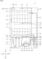
- FIG. 1 is a front perspective view illustrating a dishwasher according to the present invention
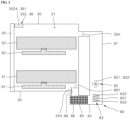
- FIG. 2 is a schematic cross-sectional view briefly illustrating an internal structure of the dishwasher according to the present invention.
- the dishwasher 1 includes a casing 10 configured to define an external shape, a tub 20 installed in the casing 10, configured to define a washing space 21 in which a washing target is washed, and having an opened front side, the door 30 configured to open or close the opened front side of the tub 20, a drive part 40 positioned below the tub 20 and configured to supply, collect, circulate, and drain washing water used to wash the washing target, an accommodation part 50 detachably provided in the washing space 21 in the tub 20 and configured such that the washing target is seated in the accommodation part 50, and a spray part disposed adjacent to the accommodation part 50 and configured to spray the washing water used to wash the washing target.
- the washing targets seated in the accommodation part 50 may be dishes, such as bowls, plates, spoons, and chopsticks, and other cookware.
- the washing target will be referred to as the dish unless otherwise stated.
- the tub 20 may be formed in a box shape having a front side entirely opened and correspond to a component known as a so-called washing tub.
- the washing space 21 may be formed in the tub 20, and the opened front side may be opened or closed by the door 30.
- the tub 20 may be formed by pressing a metal plate highly resistant to a high temperature and moisture, for example, a board made of a material such as a stainless steel.
- a plurality of brackets may be disposed on an inner surface of the tub 20, and the plurality of brackets serves to support and install functional components, such as the accommodation part 50 and the spray part to be described below, in the tub 20.
- the drive part 40 may include a sump 41 configured to store the washing water, a sump cover 42 configured to separate the sump 41 from the tub 20, a water supply part 43 configured to supply the washing water to the sump 41 from the outside, a water discharge part 44 configured to discharge the washing water in the sump 41 to the outside, and a washing pump 45 and a supply channel 46 configured to supply the washing water in the sump 41 to the spray part.
- the sump cover 42 may be disposed above the sump 41 and serve to separate the tub 20 and the sump 41.
- the sump cover 42 may have a plurality of recovery holes for recovering the washing water, which is sprayed to the washing space 21 by the spray part, into the sump 41.
- the washing water which is sprayed toward the dishes by the spray part, may fall downward to a lower side of the washing space 21 and be recovered into the sump 41 through the sump cover 42.
- the washing pump 45 is provided at one side of the sump 41 and serves to pressurize the washing water and supply the washing water to the spray part.
- the washing pump 45 may be connected to the sump 41, and the other end of the washing pump 45 may be connected to the supply channel 46.
- the washing pump 45 may include an impeller 451, a motor 453, and the like. When electric power is supplied to the motor 453, the impeller 451 may rotate, and the washing water in the sump 41 may be pressurized and then supplied to the spray part via the supply channel 46.
- a washing water heater may be provided in the washing pump 45 and serve to heat the supplied washing water during a washing step or a drying/rinsing step.
- the supply channel 46 may serve to selectively supply the spray part with the washing water supplied from the washing pump 45.
- the supply channel 46 may include a first supply channel 461 connected to a lower spray arm 61, and a second supply channel 463 connected to an upper spray arm 62 and a top nozzle 63.
- a supply channel switching valve 465 may be provided in the supply channel 46 and selectively open or close the supply channels 461 and 463.
- the supply channel switching valve 465 may be controlled to sequentially or simultaneously open the supply channels 461 and 463.
- the spray part is configured to supply the washing water to the dishes and the like accommodated in the accommodation part 50.
- the spray part may include the lower spray arm 61 positioned at a lower side of the tub 20 and configured to spray the washing water to a lower rack 51, the upper spray arm 62 positioned between the lower rack 51 and an upper rack 52 and configured to spray the washing water to the lower rack 51 and the upper rack 52, and the top nozzle 63 positioned at an upper side of the tub 20 and configured to spray the washing water to a top rack 53 or the upper rack 52.
- the lower spray arm 61 and the upper spray arm 62 may be rotatably provided in the washing space 21 of the tub 20 and spray the washing water while rotating toward the dishes in the accommodation part 50.
- the lower spray arm 61 may be rotatably supported above the sump cover 42 to spray the washing water toward the lower rack 51 while rotating at a position below the lower rack 51.
- the upper spray arm 62 may be rotatably supported by a spray arm holder 467 to spray the washing water while rotating at a position between the lower rack 51 and the upper rack 52.
- a means for switching a direction of the washing water sprayed from the lower spray arm 61 to an upward direction (U-direction) may be further provided on a lower surface 25 of the tub 20 to improve washing efficiency.
- the accommodation part 50 for accommodating the dishes may be provided in the washing space 21.
- the accommodation part 50 may be configured to be withdrawn from the inside of the tub 20 through the opened front side of the tub 20.
- FIG. 2 exemplarily illustrates an embodiment in which the accommodation part includes the lower rack 51 positioned at the lower side of the tub 20 and configured to accommodate comparatively large dishes, the upper rack 52 positioned above the lower rack 51 and configured to accommodate dishes with middle sizes, and the top rack 53 positioned at the upper side of the tub 20 and configured to accommodate dishes and the like with small sizes.
- the description will be made on the basis of the embodiment of the dishwasher 1 in which three accommodation parts 50 are provided.
- the present invention is not limited thereto.
- the lower rack 51, the upper rack 52, and the top rack 53 may be configured to be withdrawn to the outside through the opened front side of the tub 20.
- guide rails may be provided at two opposite side walls that define an inner peripheral surface of the tub 20.
- the guide rails 54 may include an upper rail, a lower rail, a top rail, and the like.
- Wheels may be provided on a lower portion of each of the lower rack 51, the upper rack 52, and the top rack 53.
- a user may withdraw the lower rack 51, the upper rack 52, and the top rack 53 to the outside through the front side of the tub 20 and easily accommodate the dishes on the lower rack 51, the upper rack 52, and the top rack 53 or easily take out the completely washed dishes from the lower rack 51, the upper rack 52, and the top rack 53.
- the guide rail 54 may be provided in the form of a stationary guide rail with a simple rail shape for withdrawing or loading the accommodation part 50 or a stretchable guide rail configured to guide the withdrawal and accommodation of the accommodation part 50 and increase a withdrawal distance in accordance with the withdrawal of the accommodation part 50.
- the door 30 serves to open or close the opened front side of the tub 20.
- a hinge part (not illustrated) is provided below the opened front side to open or close the door 30, and the door 30 is opened while rotating about the hinge part as a rotation axis.
- a handle 31 used to open the door 30 may be provided on an outer surface of the door 30, and a control panel 32 configured to control the dishwasher 1 may be provided on the outer surface of the door 30.
- control panel 32 may have a button part 34 including a display 33 configured to visually display information on a current operating state or the like of the dishwasher, a selection button to which the user's course selection manipulation is inputted, and a power button to which the user's manipulation for turning on or off the power of the dishwasher is inputted.
- an inner surface of the door 30 may define one surface of the tub 20 when the door 30 is closed, and the inner surface of the door 30 may define a seating surface on which the lower rack 51 of the accommodation part 50 may be supported when the door 30 is fully opened.
- the inner surface of the door 30 may be formed in a horizontal plane state in a direction identical to a direction in which the guide rail 54 configured to guide the lower rack 51 extends.
- a detergent supply device may be further provided on the inner surface of the door 30 and automatically supply a detergent into the tub 20.
- an automatic door opening module 352 may be provided outside the upper surface of the tub 20 to automatically open the door 30.
- the automatic door opening module 352 serves to partially open the front side of the tub 20 by moving the door 30 to a predetermined opening position in accordance with a dried state of the moisture absorbent.
- the automatic door opening module 352 may have a push rod 3524 configured to rotate an upper end of a rear surface of the door 30 to the opening position.
- a door position detection part 36 may be provided outside the upper surface of the tub 20 and detect whether the door 30 is in a closed state or an open state.
- the door position detection part 36 may include a door position sensor 361 or a latch sensor configured to detect a position of a non-illustrated door latch.
- a moisture absorption/drying device 80 may be provided at the lower side of the tub 20.
- the moisture absorption/drying device 80 may absorb water vapor contained in air discharged from the tub 20 and then resupply the air into the tub 20 during the drying step.
- the moisture absorption/drying device 80 may include a suction duct 81 configured to suck air discharged from the tub 20, a blowing part 82 configured to generate an airflow, a heater part 83 configured to heat the air sucked from the tub 20, and a moisture absorbent 85 configured to absorb water vapor contained in the air.
- an air supply hole 254 may be provided in the lower surface 25 of the tub 20 so that the air from which water vapor is removed by the moisture absorption/drying device 80 may be introduced into the tub 20.
- the moisture absorption/drying device 80 may include the blowing part 82 configured to generate an airflow of air sucked from the tub 20 and to be supplied into the tub 20, the heater part 83 having a regeneration heater 831 configured to heat the air to be supplied to the moisture absorbents 85 or the tub 20, the plurality of moisture absorbents 85 disposed at a downstream side of the blowing part 82 and the heater part 83 based on the flow direction of the airflow and configured to absorb moisture contained in the air, a housing 84 configured to accommodate the heater part 83 and the moisture absorbent 85 therein, the suction duct 81 configured to connect an air suction hole 20h of the tub 20 and the blowing part 82, and a supply duct 88 configured to guide the airflow, which has passed through the moisture absorbent 85, to the air supply hole 254 of the tub 20.
- the blowing part 82 is disposed at an upstream side of the heater part 83 and the moisture absorbent 85 and disposed at a downstream side of the suction duct 81.
- the blowing part 82 serves to suck the air from the tub 20 and generate the airflow of the air so that the sucked air may pass through the moisture absorbent 85.
- An assembly may be formed in which a blowing fan 821 and a blowing motor 822 configured to generate rotational driving power for the blowing fan are modularized together and accommodated in a housing or the suction duct 81.
- a Sirocco fan is appropriate in consideration of a positional constraint and a spatial constraint related to the installation of the blowing fan.
- the type of blowing fan 821 applied to the moisture absorption/drying device 80 is not limited.
- the heater part 83 is disposed between the blowing part 82 and the moisture absorbent 85 based on the flow direction of the airflow and serves to heat the airflow of the air to dry and regenerate the moisture absorbent 85 during the regeneration process for the moisture absorbent 85.
- the moisture absorption/drying device 80 In case that the moisture absorption/drying device 80 generates a high-temperature airflow F during the regeneration process for the moisture absorbent 85, electric power is supplied to the regeneration heater 831, such that the regeneration heater 831 heats the airflow. In case that the moisture absorption/drying device 80 generates a low-temperature airflow F during a moisture absorption process, the supply of electric power to the regeneration heater 831 may be cut off, such that the step of the regeneration heater 831 may be turned off.
- the step of the blowing fan 821 may be maintained.
- a tubular sheath heater may be selected, and the sheath heater may have a comparatively simple structure and excellent heat generation efficiency and be advantageous in preventing an electric leakage caused by the washing water introduced from the tub 20.
- the type of the regeneration heater 831 provided in the moisture absorption/drying device 80 is not limited.
- a pair of terminals 832 may be formed at one end and the other end of the regeneration heater 831 to receive electric power.
- the pair of terminals 832 may pass through the housing 84 and extend toward the outside.
- a thermostat which is configured to detect whether the regeneration heater 831 is overheated
- a thermistor which serves as a temperature sensor for detecting a temperature of the airflow
- the moisture absorbent 85 serves to absorb moisture contained in the airflow of the air discharged from the tub 20 during a moisture absorption/drying process of the moisture absorption/drying device 80, and the moisture absorbent 85 serves to discharge the absorbed moisture to the airflow during the regeneration process of the moisture absorption/drying device 80.
- the moisture absorbent 85 may be made of a reversibly dehydratable material to absorb moisture or discharge the absorbed moisture depending on the operating temperature range.
- the applicable reversibly dehydratable material may include any one of aluminum oxide, silicon oxide, silica gel, alumina silica, and zeolite or be a composition having a combination of two or more of the materials selected from these materials.
- the moisture absorbent 85 made of an alumina silica-based material including aluminum oxide and silicon oxide may be applied.
- the description will be made on the basis of the embodiment in which the moisture absorbent 85 made of an alumina silica-based material is applied.
- the present invention is not limited thereto.
- the moisture absorbent 85 which is made of an alumina silica-based material as described above, may be provided in a particle shape having a predetermined particle diameter to ensure a maximum contact area to the airflow F of the air.
- a moisture absorption action may occur within a lower temperature range, and a regeneration action may occur within a lower temperature range.
- the airflow of the air comes into contact with the moisture absorbent 85 and absorbs moisture or absorbs moisture discharged from the moisture absorbent 85 while passing between the plurality of moisture absorbents 85 provided in particle shapes.
- the moisture absorbent 85 may inevitably apply flow resistance against the airflow of the air.
- the particle diameter of the moisture absorbent 85 may be selected to effectively form pores for minimizing the flow resistance and ensure optimal moisture absorption efficiency.
- the moisture absorbent 85 having a particle diameter within a range of 2 mm to 6 mm may be selected and applied.
- the moisture absorbent 85 is disposed at a downstream side of the blowing part 82 and the heater part 83 based on the flow direction of the airflow.
- the moisture absorbent 85 may be accommodated, by a moisture absorbent holder 86, in the housing 84 provided at a downstream side of the blowing part 82 and the heater part 83.
- the moisture absorbent holder 86 may have a mesh part through which the airflow of the air may pass.
- the housing 84 of the moisture absorption/drying device 80 may serve to both accommodate the heater part 83 and the moisture absorbent 85 and define an inner flow path configured to guide a flow of the airflow having passed through the regeneration heater 831.
- the housing 84 may be manufactured to have a hollow shape to define the inner flow path.
- the supply duct 88 of the moisture absorption/drying device 80 serves (1) to allow the housing 84 to communicate with the air supply hole 254 formed in the lower surface 25 of the tub 20.
- the supply duct 88 may extend into the washing space 21 while passing through the air supply hole 254 having a tip portion communicating with the housing 84 based on the flow direction of the airflow, and a rear end formed in the lower surface 25 of the tub 20.
- a supply flow path, through which the air having passed through the moisture absorbent 85 flows, may be formed in the supply duct 88.
- the tip portion of the supply duct 88 may communicate with an outlet end side of the moisture absorbent 85 so that the airflow having passed through the moisture absorbent 85 may be introduced.
- a discharge port 881 may be connected to the rear end of the supply duct 88 and switch the flow direction of the airflow having passed through the supply flow path.
- the discharge port 881 may be formed at a position lower than the lower rack 51 based on the upward/downward direction.
- the airflow having passed through the moisture absorbent 85 may be discharged to the washing space 21 through the discharge port 881 at the position lower than the lower rack 51.
- the moisture absorption/drying device 80 may further include the suction duct 81 having a tip portion connected to the air suction hole 20h of the tub 20 based on the flow direction of the airflow, and a rear end communicating with the housing 84, and the suction duct 81 may serve to guide the airflow of the air, which is discharged from the tub 20 through the air suction hole 20h, to the housing 84.
- the interior of the suction duct 81 may be manufactured in a hollow shape to define an air passageway through which the airflow of the air may flow.
- the suction duct 81 may extend long in the upward/downward direction to connect the air suction hole 20h, which is formed to be adjacent to the upper surface of the tub 20, to the housing 84 disposed below the lower surface 25 of the tub 20.
- FIG. 4 illustrates a state in which the moisture absorption/drying device 80 operates to supply the airflow F to the tub 20 when the door 30 is in the closed state.
- the moisture absorption/drying device 80 of the dishwasher 1 may operate to perform the moisture absorption/drying process during the drying step included in a standard washing course or a general washing course as in the related art and operate to perform the regeneration process during the washing step or a heating/rinsing step.
- the moisture absorption/drying device 80 of the dishwasher 1 according to the present invention may be configured to operate even in the drying step single course in which only the drying step is performed singly and in the storage mode in which the dishes are stored for a long period of time.
- the moisture absorption/drying device 80 may operate when the door 30 is in the open state. In the state other than the above-mentioned state, the moisture absorption/drying device 80 may operate when the door 30 is in the closed state.
- the moisture absorption/drying device 80 may operate to generate the high-temperature airflow F, supply the high-temperature airflow F to the tub 20, and circulate the airflow while recovering the airflow from the tub 20.
- the blowing motor 822 may be turned on by electric power supplied to the blowing part 82, and the regeneration heater 831 may be turned on by electric power supplied to the regeneration heater 831.
- the high-temperature airflow F and high-temperature steam which are produced as the moisture absorbent 85 is regenerated and dried, may serve to increase the temperature of the washing water in case that the high-temperature airflow F and the high-temperature steam are provided during the washing step.
- the high-temperature airflow F and the high-temperature steam may be used to sterilize the dishes or remove water spots.
- the moisture absorption/drying device 80 may operate to perform the moisture absorption/drying process when the door 30 is in the closed state.
- the airflow containing moisture may be introduced into the suction duct 81 through the air suction hole 20h from the tub 20.
- the airflow introduced into the suction duct 81 may be introduced into inner flow path of the housing 84 through the regeneration heater 831. Because the regeneration heater 831 is in the turned-off state, the airflow is not heated, and the state of the low-temperature airflow F may be maintained.
- the low-temperature airflow F having passed through the regeneration heater 831 may be introduced into the moisture absorbent 85 along the supply flow path, the moisture contained in the airflow may be at least partially absorbed while passing through the moisture absorbent 85.
- the temperature of the moisture absorbent 85 may increase as the moisture absorbent 85 absorbs moisture. Therefore, the temperature of the airflow F passing through the moisture absorbent 85 may increase slightly.
- the airflow F which absorbs moisture while passing through the moisture absorbent 85, may be discharged to the washing space 21 through the supply duct 88 and the discharge port 881 and evaporate the washing water remaining on the surfaces of the dishes.
- the airflow F which is moistened while passing over the dishes in the washing space 21, may circulate while passing through the air suction hole 20h and being recovered to the moisture absorption/drying device 80.
- the moisture absorption/drying device 80 may operate when the door 30 is in the open state.
- the operating process of the moisture absorption/drying device 80 may vary depending on whether the moisture absorbent 85 is in a dried state or a moistened state.
- the "dried state of the moisture absorbent” may be defined to refer to a state in which moisture has been desorbed (dehydrate) from the moisture absorbent 85 or a state in which the moisture absorbent 85 has not absorbed water and thus may absorb moisture.
- the regeneration heater 831 may be turned on by electric power supplied to the regeneration heater 831 when the door 30 is in the open state, and the blowing motor 822 may be turned on by electric power supplied to the blowing motor 822.
- the high-temperature airflow F containing high-temperature steam may be supplied to the washing space 21 of the tub 20 in the same way as the above-mentioned regeneration process.
- the high-temperature steam provided to the washing space 21 may be used to effectively sterilize the dishes, and the temperatures of dishes and the internal temperature of the washing space 21 may be increased by the high-temperature airflow F.
- drying step single course corresponds to a course that is performed within a relatively short time in comparison with the storage mode to be described below.
- the moisture absorption/drying device 80 may operate when the door 30 is in the open state in case that the drying step single course is performed when the moisture absorbent 85 is in the moistened state so that the moisture absorbent 85 is dried after the drying step single course is completed.
- the moisture absorption/drying device 80 may operate so that the moisture absorption/drying process is performed when the door 30 is in the closed state.
- electric power may be supplied only to the blowing motor 822 when the door 30 is in the closed state, and the moisture absorption/drying process may be performed so that the drying process may be performed on the dishes within a short time.
- the dishwasher 1 may include the control unit 100 configured to control the functional components.
- control unit 100 may be provided in various forms such as a microcontroller, a microcomputer, or a microprocessor.
- control unit 100 may be electrically connected to the motor 453 of the washing pump 45 configured to pressurize the washing water stored in the sump 41 and supply the washing water to the spray part.
- the control unit 100 may initiate or stop the step of the washing pump 45 by regulating electric power to be supplied to the motor 453 from an electric power supply part 48.
- control unit 100 may initiate the operation of the washing pump 45 by supplying electric power to the motor 453 of the washing pump 45 through the electric power supply part 48.
- electric power may be supplied to operate a washing water heater 47 to moisten the internal ambience of the washing space 21 and supply moisture to the moisture absorbent 85.
- the washing water heater 47 and the washing pump 45 may operate in an operating mode similar to the heating/rinsing step S4.
- control unit 100 may be electrically connected to the button part 34 to which the user's operation instruction is inputted.
- the button part 34 may transmit an electrical signal, which corresponds to the input, to the control unit 100.
- control unit 100 When the control unit 100 receives the electrical signal from the button part 34, the control unit 100 may turn on or off the power of dishwasher 1 or control the dishwasher 1 to perform an individual step of the dishwasher 1 in accordance with the selected washing course and the selected operating mode.
- the user's operation instruction may be inputted through other input means, such as a user's wireless terminal, other than the button part 34.
- control unit 100 may be electrically connected directly and indirectly to the regeneration heater 831 configured to heat the airflow F of the air to be supplied to the moisture absorbent 85 to dry and regenerate the moisture absorbent 85.
- FIG. 7 illustrates an embodiment in which the regeneration heater 831 is configured to receive electric power indirectly from the electric power supply part 48 through the control unit 100.
- the regeneration heater 831 may be electrically connected directly to the electric power supply part 48, and the control unit 100 may be configured to control whether to supply electric power from the electric power supply part 48.
- the control unit 100 may be configured to control whether to supply electric power from the electric power supply part 48.
- the control unit 100 may turn on or off the regeneration heater 831 by regulating electric power to be supplied to the regeneration heater 831 from the electric power supply part 48 to be described below.
- the regeneration heater 831 serves to heat the airflow F of the air, a heater, which has a smaller output capacity than the washing water heater 47 for heating the washing water, may be applied.
- the regeneration heater 831 may have a rated capacity within a range of 500 to 600 W.
- control unit 100 may be electrically connected to the washing water heater 47 configured to heat the washing water to be supplied to the tub 20 during the washing step S2, the heating/rinsing step S4, and the storage mode.
- FIG. 7 illustrates an embodiment in which the washing water heater 47 is configured to receive electric power indirectly from the electric power supply part 48 through the control unit 100.
- the washing water heater 47 may be electrically connected directly to the electric power supply part 48, and the control unit 100 may be configured to control whether to supply electric power from the electric power supply part 48.
- the control unit 100 may be configured to control whether to supply electric power from the electric power supply part 48.
- the washing water heater 47 serves to heat the washing water that circulates through the tub 20. Therefore, the washing water heater may be configured to have a larger output capacity than the regeneration heater 831.
- the output capacity of the regeneration heater 831 is a rated capacity within a range of 500 to 600 W
- the output capacity of the washing water heater 47 may be a rated capacity within a range of 1,100 to 1,300 W.
- the control unit 100 may control the operations of the constituent elements of the dishwasher 1, such as the motor 453 of the washing pump 45, the regeneration heater 831, and the washing water heater 47, by regulating electric power to be supplied to the constituent elements of the dishwasher 1 in response to the progress of the step of the washing course selected by the user.
- the step parameters of the constituent elements of the dishwasher 1 are set in a memory, which will be described below, in accordance with selection options of adding or excluding the washing course and particular steps that may be selected by the user when the user pushes a button through the control panel 32, the wireless terminal, or the like.
- the step parameters such as an operating time, a degree of supply of electric power, electric power intensity, an on/off condition, and a flow rate of the washing water, of the constituent elements of the dishwasher 1, such as the washing water heater 47, the regeneration heater 831, the washing pump 45, the water discharge part 44, and the water supply part 43, may be set.
- An assembly of the step parameters, which are performed in accordance with the respective washing courses, may be defined as the operating mode.
- the washing course may mean the name of the operating mode of the dishwasher 1 displayed on a screen of the display 33 of the dishwasher 1 or the wireless terminal. That is, the user may select the washing course, and the control unit 100 of the dishwasher 1 may control the individual constituent elements of dishwasher 1 to sequentially perform the operating modes corresponding to the corresponding washing course. That is, in the present invention, the washing course and the operating mode are used separately for the specific description. However, the washing course and the operating mode may have similar meanings.
- the washing course may be variously set as a normal course, a standard course, a powerful course, a dedicate course, a half course, an automatic course (a half-loaded course in which the washing process is concentrated on some of several racks), a short course, a one-hour course, and the like.
- the designation of the name of the washing course may somewhat vary depending on the product.
- the one-hour course is performed for one hour or less, but the one-hour course may be performed for two hours or less in some instances.
- control unit 100 may determine the operating mode of the dishwasher 1 that corresponds to the washing course.
- the corresponding washing course may be performed on the basis of preset parameters.
- an option may be additionally set to each of the washing courses.
- the option may be an operating time setting of the drying step, the presence or absence of the storage mode performed after all the steps or performed as a separate course, notification on/off, and the like.
- control unit 100 may be electrically connected to the blowing motor 822 of the blowing part 82 that constitutes the moisture absorption/drying device 80.
- the control unit 100 may turn on the blowing motor 822 by supplying electric power to the blowing motor 822 through the electric power supply part 48 during the regeneration process for the moisture absorbent 85 or the moisture absorption/drying process.
- control unit 100 may be electrically connected to the memory and a timer.
- the control unit 100 may call an operating condition, a time condition, and the like for each step stored in advance for each washing course in the memory and use the operating condition, the time condition, and the like to generate control signals for controlling processes of performing or ending the steps in accordance with the washing courses.
- control unit 100 may use the timer to measure the elapsed time or the like for each step and determine whether the step is completed by comparing the elapsed time or the like with the time condition for each step stored in advance.
- the steps may include a preliminary washing step S1, the washing step S2, the rinsing step S3, the heating/rinsing step S4, and a drying step S5.
- control unit 100 may be electrically connected to the door position sensor 361 and the automatic door opening module 352.
- the control unit 100 may determine whether the door 30 is currently in the closed state or the opened state on the basis of the signal received from the door position sensor 361. In case that the door 30 needs to be opened when the door 30 is in the closed state, the control unit 100 may at least partially open the door 30 by operating the automatic door opening module 352.
- control unit 100 controls the overall washing course of the dishwasher 1 that is performed in the order of the preliminary washing step S1, the washing step S2, the rinsing step S3, the heating/rinsing step S4, and the drying step S5.
- the preliminary washing step S1 is an step of circulating the washing water by operating the washing pump 45 in a state in which the detergent is not inputted by the detergent supply device, and measuring a degree of contamination by means of a turbidity sensor (not illustrated) provided in the sump 41.
- the washing step S2 is an step of washing the dishes by circulating the washing water in a state in which the detergent is inputted by the detergent supply device.
- the rinsing step S3 and the heating/rinsing step S4 are steps of removing the detergent, which remains on the dishes, by inputting a rinse from the detergent supply device and circulating the washing water.
- the heated washing water may be supplied to heat the dishes to a predetermined temperature. Therefore, the efficiency in improving the dishes may be improved, and the drying time may be shortened during the drying step S5 to be performed after the rinsing step S3 and the heating/rinsing step S4.
- a water discharge step of discharging the washing water used for the step and a water supply step of supplying new washing water may be included between the steps.
- the water supply step may be included before the preliminary washing step S1.
- the water discharge step and the water supply step may be performed between the preliminary washing step S1 and the washing step S2, between the washing step S2 and the rinsing step S3, and between the heating/rinsing step S4 and the rinsing step S3, and a water discharge process may be performed between the heating/rinsing step S4 and the drying step S5.
- the water supply step may be performed by supplying the washing water to the sump 41 through a water supply flow path by controlling an aqua stop (not illustrated) provided in the water supply part 43.
- the water discharge step may be performed by discharging the washing water to the outside of the dishwasher 1 through a water discharge flow path by controlling the water discharge part 44 connected to the sump 41.
- control unit 100 may control the dishwasher 1 to perform the drying step single course in which only the drying step S5 is performed singly or perform the storage mode singly or as a part of the washing course.
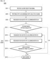
- FIG. 9 illustrates a drying step single course performing step S100 of singly performing only the drying step S5 as a first embodiment of a method S10 of controlling the dishwasher 1 according to the present invention.
- the selection of the drying step single course among the plurality of washing courses may be inputted by the user through an input means such as the button part 34, and a drying step single course selection signal may be received through the input means in response to the selection of the drying step single course (S110).
- step S110 when the drying step single course selection signal is received, the control unit 100 identifies whether the moisture absorbent 85 is currently in the moistened state or the dried state (regenerated state) before operating the moisture absorption/drying device 80 (S120).
- control unit 100 may identify the state of the moisture absorbent 85 by calling information stored in the memory and identifying which course of the washing course has been performed immediately before from the stored information.
- the control unit 100 may determine that the moisture absorbent 85 is currently in the dried state (regenerated state). In other cases, the control unit 100 may determine that the moisture absorbent 85 is currently in the moistened state.
- step S120 when it is determined that the moisture absorbent 85 is currently in the moistened state, the control unit 100 at least partially open the door 30 by operating the automatic door opening module 352 before initiating the step of the moisture absorption/drying device 80 (S130).
- step S130 when the door 30 is opened, the control unit 100 operates the moisture absorption/drying device 80 to turn on the regeneration heater 831 by supplying electric power to the regeneration heater 831 and turn on the blowing motor 822 by supplying electric power to the blowing motor 822 (S140).
- the moisture absorbent regeneration process may be initiated, and the high-temperature airflow containing high-temperature steam may be produced by the moisture absorption/drying device 80 and supplied into the tub 20.
- the moisture absorption/drying device 80 may operate similarly to the moisture absorbent regeneration process performed during the washing step S2 or the heating/rinsing step S4 in the state in which both the regeneration heater 831 and the blowing motor 822 are turned on.
- the time condition for operating the regeneration heater 831 and the blowing motor 822 and the heat generation capacity of the regeneration heater 831 may be set to be different from the conditions performed in the standard washing course or the general washing course.
- the temperature and humidity in the tub 20 during the drying step single course may be lower than the temperature and humidity in the tub 20 during the standard washing course or the general washing course.
- the operating mode of the moisture absorbent regeneration process performed in the drying step single course may be set to have a shorter time condition and a lower output temperature than the operating mode of the moisture absorbent regeneration process performed in the standard washing course or the general washing course. Therefore, the elapsed time of the drying step single course may be remarkably shortened, and the energy consumption amount may be minimized.
- step S140 When the moisture absorbent regeneration process is completed in accordance with the preset operating mode in step S140, the control unit 100 switches the regeneration heater 831 to the turned-off state by cutting off the supply of electric power to the regeneration heater 831, and the blowing motor 822 switches the step of the moisture absorption/drying device 80 to maintain the turned-on state (S150).
- the process may be switched to the moisture absorption/drying process, and a low-temperature dry airflow is generated and supplied into the tub 20, such that the dishes may be dried.
- the operating mode of the moisture absorption/drying process performed in the drying step single course may be set to have a shorter time condition than the operating mode of the moisture absorbent regeneration process performed during the drying step included in the standard washing course or the general washing course.
- step S130 the moisture absorption/drying process is performed in the state in which the door 30 is partially opened in advance, the amount of moisture absorbed by the moisture absorbent 85, i.e., the moisture absorption amount may be maintained at a minimum level in comparison with the moisture absorption/drying process performed in the standard washing course or the general washing course.
- step S150 ends, in the subsequent washing course, the moisture absorbent 85 may be maintained to be in the dried or regenerated state in which the moisture absorbent regeneration process may be excluded.
- step S150 When the moisture absorption/drying process is completed in accordance with a preset operational condition in step S150, the control unit 100 switches the step of the moisture absorption/drying device 80 to turn on the blowing motor 822 by cutting off the supply of electric power to the blowing motor 822 and ends the drying step single course (S150).
- control unit excludes steps S130 and S140 described above and immediately performs step S 150 to operate the moisture absorption/drying device 80 to turn on the blowing motor 822 by supplying electric power only to the blowing motor 822 (S150).
- the moisture absorption/drying process may be immediately performed in the state in which the process of opening the door 30 and the moisture absorbent regeneration process are excluded. Therefore, because steps S130 and S140 are excluded, the elapsed time of the drying step single course may be additionally reduced.
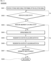
- FIGS. 10 and 11 illustrate a storage mode performing step S240 of performing the storage mode on the dishes as a second embodiment of the method S10 of controlling the dishwasher 1 according to the embodiment of the present invention.
- the storage mode may be included as a part of the washing course in accordance with the option selection, or the storage mode may be performed as a separate single course regardless of the washing course.
- FIG. 10 illustrates a configuration of performing the storage mode included in accordance with the user's option selection as a part of the washing course as a first embodiment in the second embodiment (second-first embodiment).
- the storage mode performing step which is included as a part of the washing course in accordance with the user's option selection, will be referred to as a first storage mode performing step S241.
- control unit 100 may receive the washing course selection and option selection manipulations from the user through the input means such as the button part 34 and receive signals related to the selected washing courses and options from the input means (S210).
- control unit 100 may perform the detailed steps in accordance with the selected washing courses and options S220 and S230.
- control unit 100 identifies whether a storage mode performing option is included in the user's selection option (S2411).
- control unit 100 When it is identified that the storage mode performing option is included in the user's selection option in step S2411, the control unit 100 operates the moisture absorption/drying device 80 to turn on the regeneration heater 831 by supplying electric power to the regeneration heater 831 and turn on the blowing motor 822 by supplying electric power to the blowing motor 822 (S2412).
- the moisture absorbent regeneration process may be initiated, and the high-temperature airflow containing high-temperature steam may be produced by the moisture absorption/drying device 80 and supplied into the tub 20.
- the moisture absorption/drying device 80 may operate when the door 30 is in the closed state without being opened.
- the moisture absorption/drying device 80 may operate similarly to the moisture absorbent regeneration process performed during the washing step S2 or the heating/rinsing step S4 in the state in which both the regeneration heater 831 and the blowing motor 822 are turned on.
- the time condition for operating the regeneration heater 831 and the blowing motor 822 and the heat generation capacity of the regeneration heater 831 may be set to be almost identical to the conditions of the moisture absorbent regeneration process performed in the standard washing course or the general washing course. That is, the operating mode may be set to have a higher temperature condition and a longer time condition than the moisture absorbent regeneration process S140 in the drying step single course.
- the control unit 100 switches the regeneration heater 831 to the turned-off state by cutting off the supply of electric power to the regeneration heater 831, and the blowing motor 822 switches the step of the moisture absorption/drying device 80 to maintain the turned-on state (S2413).
- the process may be switched to the moisture absorption/drying process, and a low-temperature dry airflow is generated and supplied into the tub 20, such that the dishes may be dried.
- the moisture absorption/drying process performed in step S2413 may be performed under a condition almost identical to the time condition and the temperature condition performed in the drying step S230.
- the operating mode may be set in advance to have a longer time condition than step S 150 of the moisture absorption/drying process in the drying step single course.
- step S2413 When step S2413 is completed in accordance with the preset operating mode, the control unit 100 identifies whether the elapsed time from the initiation time point of the moisture absorbent regeneration process S2412 to the completion time point of the moisture absorption/drying process S2413 reaches the designated time selected in advance by the user during the option selection process (S2414).
- the preset designated time may be set from 1 hour to 24 hours or more. That is, because the storage mode mainly serves to store the dishes in a comfortable state for a long period of time, the storage mode may be set to be much longer than the process time of the drying step single course.
- control unit 100 When it is determined that the elapsed time does not reach the preset designated time in step S2414, the control unit 100 returns to step S2412 and performs the moisture absorbent regeneration process S2412 and the moisture absorption/drying process S2413 again.
- the sterilization and moisture absorption/drying may be repeatedly performed by supplying steam until the elapsed time reaches the designated time set by the user during the storage mode. Therefore, the dishes may be stored in comfortable and sterilized states in the washing space 21 for a long period of time, which may remarkably improve the user convenience.
- control unit 100 ends the selected washing course and the first storage mode (S2415).
- control unit 100 may generate a visual or auditory alarm including information, which indicates that the selected washing course and the storage mode are completed, through the display 33, a sound output part, or the like and provide the alarm to the user.
- control unit 100 excludes the moisture absorbent regeneration process S2412 and the moisture absorption/drying process S2413, immediately performs step S2415, and ends the selected washing course.
- FIG. 11 illustrates a configuration of singly performing the storage mode separately from the washing course as a second embodiment in the second embodiment (second-second embodiment).
- the step of singly performing the storage mode performing step will be referred to as a second storage mode performing step S242.
- control unit 100 may receive the option selection manipulation, which intends to singly perform the storage mode, from the user through the input means such as the button part 34 and receive signals related to the selected options from the input means (S2421).
- step S2421 when the user's single storage mode performing selection signal is received, the control unit 100 receives an output signal from the door position sensor 361 and identifies whether the door 30 is currently in the closed state (S2422).
- step S2422 the control unit 100 is on standby without performing the storage mode.
- control unit 100 may generate an error signal including information, which indicates that the storage mode cannot be performed because the door 30 is currently in the open state, through the display 33 or the sound output part.
- control unit 100 identifies whether the moisture absorbent 85 is currently in the moistened state or the dried state (regenerated state) before operating the moisture absorption/drying device 80 (S2423).
- control unit 100 may identify the state of the moisture absorbent 85 by calling information stored in the memory and identifying which course of the washing course has been performed immediately before from the stored information.
- the control unit 100 may determine that the moisture absorbent 85 is currently in the dried state (regenerated state). In other cases, the control unit 100 may determine that the moisture absorbent 85 is currently in the moistened state.
- control unit 100 turns on the washing pump 45 and the washing water heater 47 by supplying electric power to the washing pump 45 and the washing water heater 47 and provides the heated washing water to the washing space of the tub 20 (S2424).
- Step S2424 may be performed similarly to the heating/rinsing step S4 included in the standard washing course or the general washing course. However, because the dishes currently stored in the washing space 21 has been already washed and rinsed, the operating mode may be set to have a lower operating temperature and a shorter operating time than the heating/rinsing step S4 included in the standard washing course or the general washing course.
- moisture may be supplied into the washing space 21 in the tub 20, the supplied moisture is evaporated in a moisture absorbent regeneration process S2425, which is performed subsequently, the evaporated moisture may be used as high-temperature steam, and the moisture may be absorbed by the moisture absorbent 85 in a moisture absorption/drying process S2426 subsequently performed.
- step S2424 When step S2424 is completed in accordance with the preset operating mode, the control unit 100 operates the moisture absorption/drying device 80 to turn on the regeneration heater 831 by supplying electric power to the regeneration heater 831 and turn on the blowing motor 822 by supplying electric power to the blowing motor 822 (S2425).
- the moisture absorbent regeneration process may be initiated, and the high-temperature airflow containing high-temperature steam may be produced by the moisture absorption/drying device 80 and supplied into the tub 20.
- Step S2425 may be performed in the same operating mode as step S2412 in the second-first embodiment. Therefore, the repetitive descriptions of the identical configurations will be omitted.
- the control unit 100 switches the regeneration heater 831 to the turned-off state by cutting off the supply of electric power to the regeneration heater 831, and the blowing motor 822 switches the step of the moisture absorption/drying device 80 to maintain the turned-on state (S2426).
- the process may be switched to the moisture absorption/drying process, and a low-temperature dry airflow is generated and supplied into the tub 20, such that the dishes may be dried.
- Step S2426 may be performed in the same operating mode as step S2413 in the second-first embodiment. Therefore, the repetitive descriptions of the identical configurations will be omitted.
- step S2426 When step S2426 is completed in accordance with the preset operating mode, the control unit 100 identifies whether the elapsed time from the initiation time point of the moisture absorbent regeneration process S2425 to the completion time point of the moisture absorption/drying process S2426 reaches the designated time selected in advance by the user during the option selection process (S2427).
- the preset designated time may be set from 1 hour to 24 hours or more.
- control unit 100 When it is determined that the elapsed time does not reach the preset designated time in step S2427, the control unit 100 returns to step S2425 and performs the moisture absorbent regeneration process S2425 and the moisture absorption/drying process S2426 again.
- control unit 100 ends the selected washing course and the second storage mode (S2428).
- control unit 100 may generate a visual or auditory alarm including information, which indicates that the selected washing course and the storage mode are completed, through the display 33, a sound output part, or the like and provide the alarm to the user.
- control unit 100 may exclude step S2424 described above and immediately perform step S2425.
- control unit 100 may perform the storage mode on the dishes by performing step S2425 and subsequent steps.
Landscapes
- Washing And Drying Of Tableware (AREA)
Applications Claiming Priority (1)
| Application Number | Priority Date | Filing Date | Title |
|---|---|---|---|
| KR1020230128234A KR20250045217A (ko) | 2023-09-25 | 2023-09-25 | 식기세척기 |
Publications (2)
| Publication Number | Publication Date |
|---|---|
| EP4527282A2 true EP4527282A2 (de) | 2025-03-26 |
| EP4527282A3 EP4527282A3 (de) | 2025-06-18 |
Family
ID=92746453
Family Applications (1)
| Application Number | Title | Priority Date | Filing Date |
|---|---|---|---|
| EP24199481.3A Pending EP4527282A3 (de) | 2023-09-25 | 2024-09-10 | Geschirrspülmaschine |
Country Status (3)
| Country | Link |
|---|---|
| US (1) | US20250098930A1 (de) |
| EP (1) | EP4527282A3 (de) |
| KR (1) | KR20250045217A (de) |
Citations (1)
| Publication number | Priority date | Publication date | Assignee | Title |
|---|---|---|---|---|
| EP1830690A1 (de) | 2004-12-09 | 2007-09-12 | BSH Bosch und Siemens Hausgeräte GmbH | Geschirrspülmaschine mit einer sorptionstrockenvorrichtung und verfahren zum betreiben derselben |
Family Cites Families (6)
| Publication number | Priority date | Publication date | Assignee | Title |
|---|---|---|---|---|
| DE102005004092A1 (de) * | 2004-12-09 | 2006-06-14 | BSH Bosch und Siemens Hausgeräte GmbH | Geschirrspülmaschine mit einer Sorptionstrockenvorrichtung und Verfahren zum Betreiben derselben |
| DE102008040770A1 (de) * | 2008-07-28 | 2010-02-04 | BSH Bosch und Siemens Hausgeräte GmbH | Verfahren zum Betreiben eines wasserführenden Haushaltsgerät |
| EP2323531B1 (de) * | 2008-07-28 | 2014-11-26 | BSH Bosch und Siemens Hausgeräte GmbH | Geschirrspülmaschine mit sorptionstrocknungssystem |
| DE102011003955A1 (de) * | 2011-02-10 | 2012-08-16 | BSH Bosch und Siemens Hausgeräte GmbH | Geschirrspülmaschine sowie Verfahren zum Betreiben derselben |
| KR101830690B1 (ko) | 2016-08-02 | 2018-02-22 | 한국철도기술연구원 | 산악철도차량용 차체 상부 연결 구조 |
| IT202100010955A1 (it) * | 2021-04-30 | 2022-10-30 | Ali Group S R L | Macchina asciuga-stoviglie e metodo per l’asciugatura di stoviglie in tale macchina |
-
2023
- 2023-09-25 KR KR1020230128234A patent/KR20250045217A/ko active Pending
-
2024
- 2024-09-10 EP EP24199481.3A patent/EP4527282A3/de active Pending
- 2024-09-24 US US18/894,901 patent/US20250098930A1/en active Pending
Patent Citations (1)
| Publication number | Priority date | Publication date | Assignee | Title |
|---|---|---|---|---|
| EP1830690A1 (de) | 2004-12-09 | 2007-09-12 | BSH Bosch und Siemens Hausgeräte GmbH | Geschirrspülmaschine mit einer sorptionstrockenvorrichtung und verfahren zum betreiben derselben |
Also Published As
| Publication number | Publication date |
|---|---|
| EP4527282A3 (de) | 2025-06-18 |
| US20250098930A1 (en) | 2025-03-27 |
| KR20250045217A (ko) | 2025-04-01 |
Similar Documents
| Publication | Publication Date | Title |
|---|---|---|
| EP2061921B1 (de) | Betriebsverfahren für waschmaschine | |
| AU2016297533B2 (en) | Dishwasher in the form of a commercial utensil washer or dishwasher which is designed as a batch dishwasher | |
| EP2846675B1 (de) | Verfahren zum betreiben einer als programmautomat konfigurierten geschirrspülmaschine sowie entsprechende geschirrspülmaschine | |
| EP4278945B1 (de) | Geschirrspülmaschine mit befeuchterzyklusbetrieb | |
| JP2010094247A (ja) | 食器洗い乾燥機 | |
| CA2534126C (en) | Multiple spray arm dishwashing apparatus and method for assembling same | |
| EP4527282A2 (de) | Geschirrspülmaschine | |
| KR100283720B1 (ko) | 식기세정기 및 식기의 세정방법 | |
| JPH10258014A (ja) | 食器洗浄器 | |
| JP3059861B2 (ja) | 食器洗い乾燥機 | |
| JP2975836B2 (ja) | 乾燥機及び洗浄機 | |
| CN106963316B (zh) | 洗碟机及其控制方法 | |
| US20240341560A1 (en) | Dishwasher | |
| EP4298982A1 (de) | Geschirrspülmaschine und verfahren zur steuerung davon | |
| US20070151578A1 (en) | Dishwasher and method of controlling the same | |
| TW200824631A (en) | Dishwasher | |
| KR20250046801A (ko) | 식기세척기 및 그 제어방법 | |
| KR20240023786A (ko) | 식기세척기 | |
| EP4670604A1 (de) | Geschirrspülmaschine | |
| KR20240153919A (ko) | 식기세척기 및 그 제어방법 | |
| KR20250046802A (ko) | 식기세척기 | |
| CN118806177A (zh) | 洗碗机 | |
| JP2006288925A (ja) | 食器洗い機 | |
| KR20240153895A (ko) | 식기세척기 | |
| KR20250122080A (ko) | 식기세척기 및 그 제어방법 |
Legal Events
| Date | Code | Title | Description |
|---|---|---|---|
| PUAI | Public reference made under article 153(3) epc to a published international application that has entered the european phase |
Free format text: ORIGINAL CODE: 0009012 |
|
| STAA | Information on the status of an ep patent application or granted ep patent |
Free format text: STATUS: THE APPLICATION HAS BEEN PUBLISHED |
|
| AK | Designated contracting states |
Kind code of ref document: A2 Designated state(s): AL AT BE BG CH CY CZ DE DK EE ES FI FR GB GR HR HU IE IS IT LI LT LU LV MC ME MK MT NL NO PL PT RO RS SE SI SK SM TR |
|
| PUAL | Search report despatched |
Free format text: ORIGINAL CODE: 0009013 |
|
| AK | Designated contracting states |
Kind code of ref document: A3 Designated state(s): AL AT BE BG CH CY CZ DE DK EE ES FI FR GB GR HR HU IE IS IT LI LT LU LV MC ME MK MT NL NO PL PT RO RS SE SI SK SM TR |
|
| RIC1 | Information provided on ipc code assigned before grant |
Ipc: A47L 15/42 20060101ALN20250512BHEP Ipc: A47L 15/48 20060101ALI20250512BHEP Ipc: A47L 15/00 20060101AFI20250512BHEP |
|
| STAA | Information on the status of an ep patent application or granted ep patent |
Free format text: STATUS: REQUEST FOR EXAMINATION WAS MADE |
|
| 17P | Request for examination filed |
Effective date: 20251020 |