EP4527273A1 - Cleaner station - Google Patents
Cleaner station Download PDFInfo
- Publication number
- EP4527273A1 EP4527273A1 EP23812023.2A EP23812023A EP4527273A1 EP 4527273 A1 EP4527273 A1 EP 4527273A1 EP 23812023 A EP23812023 A EP 23812023A EP 4527273 A1 EP4527273 A1 EP 4527273A1
- Authority
- EP
- European Patent Office
- Prior art keywords
- dust
- cleaner
- bag
- unit
- cartridge
- Prior art date
- Legal status (The legal status is an assumption and is not a legal conclusion. Google has not performed a legal analysis and makes no representation as to the accuracy of the status listed.)
- Pending
Links
Images









Classifications
-
- A—HUMAN NECESSITIES
- A47—FURNITURE; DOMESTIC ARTICLES OR APPLIANCES; COFFEE MILLS; SPICE MILLS; SUCTION CLEANERS IN GENERAL
- A47L—DOMESTIC WASHING OR CLEANING; SUCTION CLEANERS IN GENERAL
- A47L9/00—Details or accessories of suction cleaners, e.g. mechanical means for controlling the suction or for effecting pulsating action; Storing devices specially adapted to suction cleaners or parts thereof; Carrying-vehicles specially adapted for suction cleaners
- A47L9/10—Filters; Dust separators; Dust removal; Automatic exchange of filters
- A47L9/106—Dust removal
-
- A—HUMAN NECESSITIES
- A47—FURNITURE; DOMESTIC ARTICLES OR APPLIANCES; COFFEE MILLS; SPICE MILLS; SUCTION CLEANERS IN GENERAL
- A47L—DOMESTIC WASHING OR CLEANING; SUCTION CLEANERS IN GENERAL
- A47L9/00—Details or accessories of suction cleaners, e.g. mechanical means for controlling the suction or for effecting pulsating action; Storing devices specially adapted to suction cleaners or parts thereof; Carrying-vehicles specially adapted for suction cleaners
- A47L9/28—Installation of the electric equipment, e.g. adaptation or attachment to the suction cleaner; Controlling suction cleaners by electric means
- A47L9/2868—Arrangements for power supply of vacuum cleaners or the accessories thereof
- A47L9/2873—Docking units or charging stations
-
- A—HUMAN NECESSITIES
- A47—FURNITURE; DOMESTIC ARTICLES OR APPLIANCES; COFFEE MILLS; SPICE MILLS; SUCTION CLEANERS IN GENERAL
- A47L—DOMESTIC WASHING OR CLEANING; SUCTION CLEANERS IN GENERAL
- A47L5/00—Structural features of suction cleaners
- A47L5/12—Structural features of suction cleaners with power-driven air-pumps or air-compressors, e.g. driven by motor vehicle engine vacuum
- A47L5/22—Structural features of suction cleaners with power-driven air-pumps or air-compressors, e.g. driven by motor vehicle engine vacuum with rotary fans
- A47L5/24—Hand-supported suction cleaners
-
- A—HUMAN NECESSITIES
- A47—FURNITURE; DOMESTIC ARTICLES OR APPLIANCES; COFFEE MILLS; SPICE MILLS; SUCTION CLEANERS IN GENERAL
- A47L—DOMESTIC WASHING OR CLEANING; SUCTION CLEANERS IN GENERAL
- A47L7/00—Suction cleaners adapted for additional purposes; Tables with suction openings for cleaning purposes; Containers for cleaning articles by suction; Suction cleaners adapted to cleaning of brushes; Suction cleaners adapted to taking-up liquids
- A47L7/0095—Suction cleaners or attachments adapted to collect dust or waste from power tools
-
- A—HUMAN NECESSITIES
- A47—FURNITURE; DOMESTIC ARTICLES OR APPLIANCES; COFFEE MILLS; SPICE MILLS; SUCTION CLEANERS IN GENERAL
- A47L—DOMESTIC WASHING OR CLEANING; SUCTION CLEANERS IN GENERAL
- A47L9/00—Details or accessories of suction cleaners, e.g. mechanical means for controlling the suction or for effecting pulsating action; Storing devices specially adapted to suction cleaners or parts thereof; Carrying-vehicles specially adapted for suction cleaners
- A47L9/0009—Storing devices ; Supports, stands or holders
- A47L9/0063—External storing devices; Stands, casings or the like for the storage of suction cleaners
-
- A—HUMAN NECESSITIES
- A47—FURNITURE; DOMESTIC ARTICLES OR APPLIANCES; COFFEE MILLS; SPICE MILLS; SUCTION CLEANERS IN GENERAL
- A47L—DOMESTIC WASHING OR CLEANING; SUCTION CLEANERS IN GENERAL
- A47L9/00—Details or accessories of suction cleaners, e.g. mechanical means for controlling the suction or for effecting pulsating action; Storing devices specially adapted to suction cleaners or parts thereof; Carrying-vehicles specially adapted for suction cleaners
- A47L9/10—Filters; Dust separators; Dust removal; Automatic exchange of filters
- A47L9/102—Dust separators
-
- A—HUMAN NECESSITIES
- A47—FURNITURE; DOMESTIC ARTICLES OR APPLIANCES; COFFEE MILLS; SPICE MILLS; SUCTION CLEANERS IN GENERAL
- A47L—DOMESTIC WASHING OR CLEANING; SUCTION CLEANERS IN GENERAL
- A47L9/00—Details or accessories of suction cleaners, e.g. mechanical means for controlling the suction or for effecting pulsating action; Storing devices specially adapted to suction cleaners or parts thereof; Carrying-vehicles specially adapted for suction cleaners
- A47L9/10—Filters; Dust separators; Dust removal; Automatic exchange of filters
- A47L9/14—Bags or the like; Rigid filtering receptacles; Attachment of, or closures for, bags or receptacles
- A47L9/1427—Means for mounting or attaching bags or filtering receptacles in suction cleaners; Adapters
-
- A—HUMAN NECESSITIES
- A47—FURNITURE; DOMESTIC ARTICLES OR APPLIANCES; COFFEE MILLS; SPICE MILLS; SUCTION CLEANERS IN GENERAL
- A47L—DOMESTIC WASHING OR CLEANING; SUCTION CLEANERS IN GENERAL
- A47L9/00—Details or accessories of suction cleaners, e.g. mechanical means for controlling the suction or for effecting pulsating action; Storing devices specially adapted to suction cleaners or parts thereof; Carrying-vehicles specially adapted for suction cleaners
- A47L9/10—Filters; Dust separators; Dust removal; Automatic exchange of filters
- A47L9/14—Bags or the like; Rigid filtering receptacles; Attachment of, or closures for, bags or receptacles
- A47L9/1481—Means for removing bags in suction cleaners, e.g. ejecting means; Means for exchanging bags
Definitions
- the present invention relates to a cleaner station, and more specifically, to a cleaner station capable of separating dust contained in the air, collecting the dust in a dust bag, and emptying only the dust bag.
- a cleaner is a home appliance for suctioning small trash or dust in a manner of suctioning air using electricity and filling the same in a dust bin inside a product and is commonly called a vacuum cleaner.
- the vacuum cleaner may be classified into a manual vacuum cleaner for allowing a user to directly perform cleaning while moving the cleaner, and an automatic vacuum cleaner for performing cleaning while traveling by itself.
- the manual vacuum cleaner may be classified into a canister-type vacuum cleaner, an upright vacuum cleaner, a hand vacuum cleaner, a stick-type vacuum cleaner, etc.
- the canister-type vacuum cleaner was widely used as the household vacuum cleaner, but recently, the hand vacuum cleaner and the stick-type vacuum cleaner, which provide improved convenience of use by integrally providing a dust bin and a cleaner body, are increasingly being used.
- the canister-type vacuum cleaner has a main body and a suction port connected by a rubber hose or a pipe and in some cases, may be used by inserting a brush into the suction port.
- the hand vacuum cleaner is designed to maximize portability and has lightweight and a short length, and thus can have a limited cleaning area. Therefore, the hand vacuum cleaner is used to clean localized sites, such as on a desk, a sofa, or a vehicle interior.
- a user may use the stick-type vacuum cleaner while standing to enable cleaning without bending down. Therefore, it is advantageous for cleaning a wide region while moving. While the hand vacuum cleaner cleans narrow spaces, the stick-type vacuum cleaner may clean wider spaces and clean high places out of reach. Recently, the stick-type vacuum cleaner has been provided in a module type to allow users to actively change a vacuum cleaner type for various purposes.
- a robot cleaner may automatically clean an area to be cleaned by suctioning foreign substances, such as dust, from the floor while autonomously traveling in the area to be cleaned.
- Korean Patent Registration KR10-2161708B1 discloses a station including a dust bag.
- the related art document includes a station to which a dust bin of a cleaner is coupled, and a dust bag is disposed at a station.
- the dust bag is coupled to the inside of a housing of the cleaner along a sliding groove, and an outer surface of the dust bag is formed of a material that may filter dust while passing through air.
- the Korea Laid-Open Patent KR10-2021-0019940A discloses a cleaner station for collecting dust collected in a dust bin of the cleaner.
- the related art document includes a cleaner for suctioning and storing dust in the air, and a cleaner station coupled to the dust bin to remove dust stored in the dust bin, in which a dust collection motor for suctioning foreign substances and internal air in the dust bin coupled to the cleaner station and a plastic bag-type dust collection unit.
- the cleaner station may be crushed flat as the plastic bag is pulled toward the dust collection motor when the dust collection motor is operated.
- the cleaner station cannot easily collect dust in the plastic bag as an internal space of the plastic bag narrows when the dust collection motor is operated.
- the present invention has been intended to solve the above problems of the conventional cleaner stations and is directed to providing a clean station capable of stably maintaining a shape of a dust bag while dust is collected.
- the present invention is directed to providing a cleaner station capable of separating dust from air and collecting the dust in a dust bag while the air containing the dust flows toward a dust collection motor.
- the present invention is directed to providing a cleaner station that does not require a user to directly tie a dust bag.
- the present invention is directed to providing a cleaner station capable of emptying a dust bin by allowing a user to remove only a dust bag.
- the dust collection unit may include a dust separator that separates dust in the air introduced from the dust bin, a dust bag that stores dust separated by the dust separator, a bag support that accommodates the dust bag, and a dust bag cartridge separably coupled under the dust separator and supplying the dust bag.
- the bonding unit may include a bonding unit case, and a cartridge detection sensor provided on a top surface of the bonding unit case and detecting whether the dust bag cartridge is coupled.
- the cleaner 200 may be a cleaner that is manually manipulated by a user.
- the cleaner 200 may be a hand cleaner or a stick-type cleaner.
- the cleaner 200 may be caught on the cleaner station 100.
- the cleaner 200 may be supported by the cleaner station 100.
- the cleaner 200 may be coupled to the cleaner station 100.
- a direction of the cleaner 200 can be defined based on when bottom surfaces (lower surfaces) of the dust bin 220 and a battery housing 230 are placed on the ground.
- the front may be a direction in which a suction unit 212 is disposed with respect to a suction motor 214
- the rear may be a direction in which a handle 216 is disposed with respect to to the suction motor 214.
- a direction located at the right may be referred to as a right side
- a direction located at the left may be referred to as a left side with respect to when viewing the suction unit 212 from the suction motor 214.
- top and bottom can be defined in a direction perpendicular to the ground with respect to when the bottom surfaces (lower surfaces) of the dust bin 220 and the battery housing 230 are placed on the ground.
- the cleaner 200 may include a main body 210.
- the main body 210 may include a main body housing 211, the suction unit 212, a dust separator 213, a suction motor 214, an air discharge cover 215, the handle 216, and a manipulation unit 218.
- the main body housing 211 may form the appearance of the cleaner 200.
- the main body housing 211 may provide a space in which the suction motor 214 and a filter (not shown) may be accommodated.
- the main body housing 211 may be formed in substantially a cylindrical shape.
- the suction unit 212 may protrude outward from the main body housing 211.
- the suction unit 212 may be formed in a cylindrical shape with an open interior.
- the suction unit 212 may be coupled to an extension pipe 250.
- the suction unit 212 may provide a flow path (hereinafter referred to as "suction flow path") through which air containing dust may flow.
- a virtual line passing through the inside of the suction unit 212 formed in a cylindrical shape may be formed.
- the dust separator 213 may communicate with the suction unit 212.
- the dust separator 213 may separate dust suctioned therein through the suction unit 212.
- An internal space of the dust separator 213 may communicate with an internal space of the dust bin 220.
- the dust separator 213 may have at least one cyclone unit capable of separating dust by a cyclonic flow.
- the internal space of the dust separator 213 may communicate with the suction flow path. Therefore, the air and dust suctioned through the suction unit 212 spirally flow along an inner circumferential surface of the dust separator 213. Therefore, a cyclonic flow may occur in the internal space of the dust separator 213.
- the dust separator 213 is a component that communicates with the suction unit 212 and adopts the principle of a dust collector using a centrifugal force to separate dust suctioned into the main body 210 through the suction unit 212.
- the dust separator 213 may further include a secondary cyclone that re-separates dust from the air discharged from the cyclone.
- the secondary cyclone may be located inside the cyclone to minimize a size of the dust separator.
- the secondary cyclone may include a plurality of cyclone bodies disposed in parallel. The air discharged from the cyclone may be partitioned into the plurality of cyclone bodies and may pass through the same.
- an axis of the cyclonic flow of the secondary cyclone may extend vertically, and an axis of the cyclonic flow of the cyclone and the axis of the cyclonic flow of the secondary cyclone may be coaxial vertically and may be collectively referred to as an axis of the cyclonic flow of the dust separator 213.
- the suction motor 214 may generate a suction force of suctioning air.
- the suction motor 214 may be accommodated in the main body housing 211.
- the suction motor 214 may generate a suction force by rotation.
- the suction motor 214 may be provided in a shape similar to a cylindrical shape.
- a virtual suction motor axial line extending a rotational axis of the suction motor 214 may be formed.
- the air discharge cover 215 may be disposed at one side of the main body housing 211 in the axial direction.
- the air discharge cover 215 may accommodate a filter for filtering air.
- the air discharge cover 215 may accommodate a HEPA filter.
- An air outlet through which the air suctioned by the suction force of the suction motor 214 is discharged may be formed on the air discharge cover 215.
- a flow guide may be disposed on the air discharge cover 215.
- the flow guide may guide a flow of the air discharged through the air outlet.
- the handle 216 may be gripped by a user.
- the handle 216 may be disposed behind the suction motor 214.
- the handle 216 may be formed in a shape similar to a cylindrical shape.
- the handle 216 may be formed in a curved cylindrical shape.
- the handle 216 may be disposed at a predetermined angle with the main body housing 211, the suction motor 214, or the dust separator 213.
- the handle 216 may include a grip portion 216a formed in a pillar shape to allow the user to grip the same, a first extension 216b connected to one end portion of the grip portion 216a in a longitudinal direction (axial direction) and formed to extend toward the suction motor 214, and a second extension 216c connected to the other end portion of the first extension 216b and the grip portion 216a in the longitudinal direction (axial direction) and formed to extend toward the dust bin 220.
- a virtual grip portion penetration line formed to extend in the longitudinal direction of the grip portion 216a (axial direction of a pillar) and penetrating the grip portion may be formed.
- the grip portion penetration line may be a virtual line formed inside the cylindrical handle 216 and may be a virtual line formed parallel to at least a portion of an outer surface (outer perimetric surface) of the grip portion 216a.
- An upper surface of the handle 216 may form a partial appearance of an upper surface of the cleaner 200. Therefore, when the user grips the handle 216, one component of the cleaner 200 can be prevented from coming into contact with the user's arm.
- the first extension may extend from the grip portion 216a toward the main body housing 211 or the suction motor 214. At least a portion of the first extension may extend in a horizontal direction.
- the second extension may extend from the grip portion 216a to the dust bin 220. At least a portion of the second extension may extend in the horizontal direction.
- the manipulation unit 218 may be disposed on the handle 216.
- the manipulation unit 218 may be disposed on an inclined surface formed on an upper region of the handle 216.
- the user may input an operation or stop command of the cleaner 200 through the manipulation unit 218.
- the cleaner 200 may include the dust bin 220.
- the dust bin 220 may communicate with the dust separator 213.
- the dust bin 220 may store the dust separated by the dust separator 213.
- the dust bin 220 may include a dust bin main body 221, a discharge cover 222, a dust bin compression lever 223, and a compression member (not shown).
- the dust bin main body 221 may provide a space in which the dust separated by the dust separator 213 may be stored.
- the dust bin main body 221 may be formed in a shape similar to a cylindrical shape.
- a virtual dust bin penetration line which penetrates the inside (internal space) of the dust bin main body 221 and formed to extend in the longitudinal direction (which is an axial direction in the cylindrical dust bin main body 221) of the dust bin main body 221, may be formed.
- a portion of a bottom surface (floor surface) of the dust bin main body 221 may be open.
- a lower surface extension 221a may be formed on the bottom surface (floor surface) of the dust bin main body 221.
- the lower surface extension 221a may be formed to block a portion of the bottom surface of the dust bin main body 221.
- the dust bin 220 may include the discharge cover 222.
- the discharge cover 222 may be disposed on the bottom surface of the dust bin 220.
- the discharge cover 222 may be provided to open and close one end portion of the dust bin main body 221 in the longitudinal direction. Specifically, the discharge cover 222 may selectively open and close a downward open lower portion of the dust bin 220.
- the discharge cover 222 may include a cover main body 222a and a hinge unit 222b.
- the cover main body 222a may be formed to block a portion of the bottom surface of the dust bin main body 221.
- the cover main body 222a may rotate downward with respect to the hinge unit 222b.
- the hinge unit 222b may be disposed adjacent to the battery housing 230.
- the hinge unit 222b may be provided with a torsion spring 222d. Therefore, when the discharge cover 222 is separated from the dust bin main body 221, the cover main body 222a may be supported while rotated about the hinge unit 222b at a predetermined angle or more in the dust bin main body 221 by an elastic force of the torsion spring 222d.
- the discharge cover 222 may be coupled to the dust bin 220 through hook coupling. Meanwhile, the discharge cover 222 may be separated from the dust bin 220 through a coupling lever 222c.
- the coupling lever 222c may be disposed at the front of the dust bin. Specifically, the coupling lever 222c may be disposed on a front outer surface of the dust bin 220. When an external force is applied, the coupling lever 222c may elastically deform a hook extending from the cover main body 222a to release hook coupling between the cover main body 222a and the dust bin main body 221.
- the bottom surface of the dust bin 220 may be blocked (sealed) by the discharge cover 222 and the lower surface extension 221a.
- the compression member (not shown) may be disposed inside the dust bin main body 221.
- the compression member may move in an internal space of the dust bin main body 221. Specifically, the compression member may move upward and downward in the dust bin main body 221. Therefore, the compression member may compress the dust in the dust bin main body 221 downward.
- the compression member may move from the upper portion to the lower portion of the dust bin 220 to remove foreign substances such as the remaining dust in the dust bin 220. Therefore, it is possible to increase the suction force of the cleaner by preventing the remaining dust from remaining in the dust bin 220.
- bad odors generated by the residue can be removed by preventing the remaining dust from remaining in the dust bin 220.
- the cleaner 200 may include the battery housing 230.
- a battery 240 may be accommodated in the battery housing 230.
- the battery housing 230 may be disposed under the handle 216.
- the battery housing 230 may have a hexahedral shape with an open lower portion.
- a rear surface of the battery housing 230 may be connected to the handle 216.
- the battery housing 230 may include an accommodation portion that is opened downward.
- the battery 240 may be detachably attached through the accommodation portion of the battery housing 220.
- the battery 240 may be detachably coupled to the cleaner 200.
- the battery 240 may be detachably coupled to the battery housing 230.
- the battery 240 may be inserted into the battery housing 230 from the bottom of the battery housing 230. With this configuration, it is possible to improve the portability of the cleaner 200.
- the battery 240 may be provided integrally inside the battery housing 230. In this case, a lower surface of the battery 240 is not externally exposed.
- the battery 240 may supply power to the suction motor 214 of the cleaner 200.
- the battery 240 may be disposed under the handle 216.
- the battery 240 may be disposed behind the dust bin 220.
- the lower surface of the battery 240 when the battery 240 is coupled to the battery housing 230, the lower surface of the battery 240 may be externally exposed. Since the battery 240 may be placed on the floor when the cleaner 200 is placed on the floor, the battery 240 may be immediately separated from the battery housing 230. In addition, since the lower surface of the battery 240 is externally exposed and come into direct contact with the external air of the battery 240, it is possible to improve cooling performance of the battery 240.
- the structure for attaching and detaching the battery 240 and the battery housing 230 can be smaller, thereby reducing the overall size of the cleaner 200 and achieving lightweight.
- the cleaner 200 may include the extension pipe 250.
- the extension pipe 250 may communicate with a cleaning module 260.
- the extension pipe 250 may communicate with the main body 210.
- the extension pipe 250 may communicate with the suction unit 214 of the main body 210.
- the extension pipe 250 may be formed in a long cylindrical shape.
- the main body 210 may be connected to the extension pipe 250.
- the main body 210 may be connected to the cleaning module 260 through the extension pipe 250.
- the main body 210 may generate the suction force through the suction motor 214 and provide the suction force to the cleaning module 260 through the extension pipe 250. External dust may flow into the main body 210 through the cleaning module 260 and the extension pipe 250.
- the cleaner 200 may include the cleaning module 260.
- the cleaning module 260 may communicate with the extension pipe 250. Therefore, external air may pass through the cleaning module 260 and the extension pipe 250 and flow into the main body 210 of the cleaner 200 by the suction force generated from the main body 210 of the cleaner 200.
- Dust in the dust bin 220 of the cleaner 200 may be collected in the dust collection unit 170 of the cleaner station 100 by gravity and the suction force of a dust collection motor 191. Therefore, since the dust in the dust bin can be removed without the user's separate manipulation, user convenience can be provided. In addition, it is possible to eliminate the user's inconvenience having to empty the dust bin every time. In addition, it is possible to prevent the scattering of dust when the user empties the dust bin.
- the cleaner 200 may be coupled to a side surface of a housing 110. Specifically, the main body 210 of the cleaner 200 may be caught on a coupling unit 120. More specifically, the dust bin 220 and the battery housing 230 of the cleaner 200 may be coupled to a coupling surface 121, an outer circumferential surface of the dust bin main body 221 may be coupled to a dust bin guide surface 122, and the suction unit 212 may be coupled to a suction unit guide surface 126 of the coupling unit 120. In this case, a central axis of the dust bin 220 may be disposed in a direction parallel to the ground, and the extension pipe 250 may be disposed in a direction perpendicular to the ground.
- FIG. 5 shows a view for describing a coupling part in a cleaner station according to one embodiment of the present invention
- FIG. 6 shows a perspective view for describing a fixing unit in the cleaner station according to one embodiment of the present invention
- FIGS. 7 and 8 show views for describing the relationship between the cleaner and a door unit in the cleaner station according to the embodiment of the present invention
- FIG. 9 shows a view for describing the relationship between the cleaner and a cover opening unit in the cleaner station according to the embodiment of the present invention.
- the cleaner station 100 of the present invention will be described with reference to FIGS. 5 to 9 as follows.
- the cleaner 200 may be coupled to the cleaner station 100. Specifically, the main body of the cleaner 200 may be coupled to the side surface of the cleaner station 100.
- the cleaner station 100 may remove dust of the dust bin 220 of the cleaner 200.
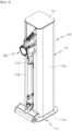
- the cleaner station 100 may include the housing 110.
- the housing 110 may form the appearance of the cleaner station 100.
- the housing 110 may be formed in a pillar shape including at least one outer wall surface.
- the housing 110 may be formed in a shape similar to a quadrangular pillar.
- the housing 110 may have a space in which the dust collection unit 170 for storing dust therein and the dust suction module 190 for generating a flow force of collecting dust into the dust collection unit 170 may be accommodated.
- the housing 110 may include a floor surface 111, an outer wall surface 112, and an upper surface 113.
- the floor surface 111 may support a bottom of the dust suction module 190 in a direction of gravity. That is, the floor surface 111 may support the bottom of the dust collection motor 191 of the dust suction module 190.
- the floor surface 111 may be disposed toward the ground.
- the floor surface 111 may be not only disposed parallel to the ground, but also disposed to be inclined at a predetermined angle with the ground.
- the floor surface 111 may further include a ground support 311a that increases an area in contact with the ground to prevent the cleaner station 100 from falling and maintain balance.
- the ground support 311a may be in the form of a plate extending from the floor surface 111, and one or more frames may be formed to protrude and extend from the floor surface 111 in the direction of the ground.
- the outer wall surface 112 may be a surface formed in the direction of gravity and may be a surface connected to the floor surface 111.
- the outer wall surface 112 may be a surface connected perpendicular to the floor surface 111.
- the outer wall surface 112 may be disposed to be inclined at a predetermined angle with the floor surface 111.
- the outer wall surface 112 may include at least one surface.
- the outer wall surface 112 may include a first outer wall surface 112a, a second outer wall surface 112b, a third outer wall surface 112c, and a fourth outer wall surface 112d.
- the first outer wall surface 112a may be disposed on a front surface of the cleaner station 100.
- the front surface may be a surface on which the cleaner 200 is exposed while the cleaner 200 is coupled to the cleaner station 100. Therefore, the first outer wall surface 112a may form the appearance of the front surface of the cleaner station 100.
- directions are defined as follows.
- directions can be defined in a state in which the cleaner 200 is caught on the cleaner station 100.
- a direction in which the cleaner 200 is exposed externally from the cleaner station 100 may be referred to as the front.
- a direction in which the suction motor 214 of the cleaner 200 is disposed may be referred to as the front.
- a direction opposite to the direction in which the suction motor 214 is disposed in the cleaner station 100 may be referred to as the rear.
- a surface in a direction facing the front surface with respect to the internal space of the housing 110 may be referred to as the rear surface of the cleaner station 100. Therefore, the rear surface may refer to a direction in which the second outer wall surface 112b is formed.
- a surface at the left may be referred to as a left surface
- a surface at the right may be referred to as a right surface. Therefore, the left surface may refer to a direction in which the third outer wall surface 112c is formed, and the right surface may refer to the direction in which the fourth outer wall surface 112d is formed.
- the first outer wall surface 112a may be formed not only in a flat shape, but also entirely in a curved shape, and a portion thereof may be formed to include a curved surface.
- the coupling unit 120 may be disposed on the first outer wall surface 112a. With this configuration, the cleaner 200 may be coupled to the cleaner station 100 and supported by the cleaner station 100. A detailed configuration of the coupling unit 120 will be described below.
- a structure for holding any type of cleaning module 260 used in the cleaner 200 may be added to the first outer wall surface 112a.
- the second outer wall surface 112b may be a surface facing the first outer wall surface 112a. That is, the second outer wall surface 112b may be disposed on the rear surface of the cleaner station 100. The second outer wall surface 112b may form the appearance of the rear surface of the cleaner station 100.
- the third outer wall surface 112c and the fourth outer wall surface 112d may be surfaces that connect the first outer wall surface 112a with the second outer wall surface 112b.
- the third outer wall surface 112c may be disposed on the left surface of the cleaner station 100, and the fourth outer wall surface 112d may be disposed on the right surface of the cleaner station 100.
- the third outer wall surface 112c may be disposed on the right surface of the cleaner station 100, and the fourth outer wall surface 112d may be disposed on the left surface of the cleaner station 100.
- the third outer wall surface 112c or the fourth outer wall surface 112d may be formed not only in a flat shape, but also entirely in a curved shape, and portions thereof may be formed to include a curved surface.
- a structure for holding any type of cleaning module 290 used in the cleaner 200 may be added to the third outer wall surface 112c or the fourth outer wall surface 112d.
- the upper surface 113 may form the appearance of the top of the cleaner station. That is, the upper surface 113 may be a surface that is disposed at the uppermost side of the cleaner station in the direction of gravity and exposed externally.
- top and bottom may be top and bottom, respectively, in the direction of gravity (direction perpendicular to the ground) in a state in which the cleaner station 100 is installed on the ground.
- the upper surface 113 may be disposed not only parallel to the ground, but also to be inclined at a predetermined angle with the ground.
- a display unit may be disposed on the upper surface 113.
- the display unit may display the state of the cleaner station 100 and the state of the cleaner 200 and also display pieces of information such as a cleaning progress situation and a map of a cleaning area.
- the upper surface 113 may be provided separately from the outer wall surface 112.
- a battery separated from the cleaner 200 may be accommodated in the internal space surrounded by the outer wall surface 112 and provided with a terminal (not shown) for charging the separated battery.
- a bag accommodation space 115 may be formed inside the housing 110.
- the bag accommodation space 115 may be disposed under the coupling unit 120 in the direction of gravity and disposed above the dust suction module 190 in the direction of gravity.
- the dust collection unit 170 may be provided in the bag accommodation space 115.
- a bag support 173 described below may be accommodated to be accessible in the bag accommodation space 115.
- a dust bag cartridge 174 described below may be detachably coupled to the bag accommodation space 115.
- a bonding unit 176 described below may be mounted in the bag accommodation space 115.
- the bag accommodation space 115 may communicate with a first flow path 181, a second flow path 182, and a bypass flow path 183, which will be described below. With this configuration, the bag accommodation space 115 may provide a space in which air and dust introduced from the dust bin 220 may flow and may be collected in a dust bag 172.
- the cleaner 200 may be mounted on the outer wall surface 112 of the cleaner station 100.
- the dust bin 220 and the battery housing 230 of the cleaner 200 may be coupled to the coupling surface 121 of the cleaner station 100. That is, the cleaner 200 may be caught on the first outer wall surface 112a.
- an axial line of the suction motor 214 may be formed perpendicular to the first outer wall surface 112a. That is, the axial line of the suction motor 214 may be formed parallel to the ground.
- a virtual line penetrating the dust bin 220 may be formed perpendicular to the first outer wall surface 112a.
- An axial line C of the housing 110 in the longitudinal direction may be formed perpendicular to the ground.
- the axial line C of the housing 110 in the longitudinal direction may be formed parallel to at least one of the first outer wall surface 112a, the second outer wall surface 112b, the third outer wall surface 112c, and the fourth outer wall surface 112d.
- an axial line of the suction motor 214 may intersect an axial line of the cleaner station 100 in the longitudinal direction. That is, the rotational axis of the suction motor 214 may intersect the axis of the cleaner station 100 in the longitudinal direction.
- the battery 240 may be disposed at a farther distance from the ground than the rotational axis of the suction motor 214. With this configuration, the cleaner 200 may be stably supported by the cleaner station 100.
- a virtual line penetrating the dust bin 220 may intersect the axis of the cleaner station 100 in the longitudinal direction. That is, the axis of the dust bin 220 in the longitudinal direction may intersect the axis of the cleaner station 100 in the longitudinal direction. In this case, an intersection of the axis of the dust bin 220 and the axis of the cleaner station 100 in the longitudinal direction may be located inside the housing 110, and more specifically, located inside the flow path unit 180.
- the handle 216 may be disposed at a farther distance from the ground than the virtual line penetrating the dust bin 220.
- the coupling unit 120 of the cleaner station 100 of the present invention will be described with reference to FIG. 5 as follows.
- the cleaner station 100 may include the coupling unit 120 to which the cleaner 200 is coupled.
- the coupling unit 120 may be disposed on the first outer wall surface 112a, and the main body 210, the dust bin 220, and the battery housing 230 of the cleaner 200 may be coupled.
- the coupling unit 120 may include the coupling surface 121.
- the coupling surface 121 may be disposed on a side surface of the housing 110.
- the coupling surface 121 may be a surface formed in a groove shape that is concave from the first outer wall surface 112a to the inside of the cleaner station 100. That is, the coupling surface 121 may be a surface formed by forming a step with the first outer wall surface 112a.
- the cleaner 200 may be coupled to the coupling surface 121.
- the coupling surface 121 may come into contact with the bottom surfaces of the dust bin 220 and the battery housing 230 of the cleaner 200.
- the bottom surface may be a surface facing the ground when the user uses the cleaner 200 or places the cleaner 200 on the ground.
- an angle formed by the coupling surface 121 and the ground may be a right angle. Therefore, when the cleaner 200 is coupled to the coupling surface 121, it is possible to minimize a space of the cleaner station 100.
- the coupling surface 121 may be disposed to be inclined at a predetermined angle with the ground. Therefore, when the cleaner 200 is coupled to the coupling surface 121, the cleaner station 100 can be stably supported.
- a dust through hole 121a may be formed in the coupling surface 121 to allow external air of the housing 110 to flow therein.
- the dust through hole 121a may be formed in a hole shape corresponding to the shape of the dust bin 220 so that the dust in the dust bin 220 flows into the dust collection unit 170.
- the dust through hole 121a may be formed to correspond to the shape of the discharge cover 222 of the dust bin 220.
- the dust through hole 121a may be formed to communicate with the flow path unit 180 described below.
- the coupling unit 120 may include the dust bin guide surface 122.
- the dust bin guide surface 122 may be disposed on the first outer wall surface 112a.
- the dust bin guide surface 122 may be connected to the first outer wall surface 112a.
- the dust bin guide surface 122 may be connected to the coupling surface 121.
- the dust bin guide surface 122 may be formed in a shape corresponding to the outer surface of the dust bin 220.
- the front outer surface of the dust bin 220 may be coupled to the dust bin guide surface 122. Therefore, the convenience of coupling the cleaner 200 to the coupling surface 121 can be provided.
- a protrusion movement hole 122a may be formed in the dust bin guide surface 122, and a push protrusion 151 described below may move linearly along the protrusion movement hole 122a.
- a gear box 155 for accommodating a gear of the cover opening unit 150 described below and the like may be provided under the dust bin guide surface 122 in the direction of gravity.
- a guide space 122b in which the push protrusion 151 may move may be formed between a bottom surface of the dust bin guide surface 122 and a top surface of the gear box 155.
- the guide space 122b may communicate with the first flow path 181 through a bypass hole 122c.
- the protrusion movement hole 122a, the guide space 122b, the bypass hole 122c, and the first flow path 181 may form one flow path.
- the coupling unit 120 may include a guide protrusion 123.
- the guide protrusion 123 may be disposed on the coupling surface 121.
- the guide protrusion 123 may protrude upward from the coupling surface 121.
- Two guide protrusions 123 may be disposed to be spaced apart from each other. A distance between the two guide protrusions 123 spaced apart from each other may correspond to a width of the battery housing 230 of the cleaner 200. Therefore, the convenience of coupling the cleaner 200 to the coupling surface 121 can be provided.
- the coupling unit 120 may include a coupling unit side wall 124.
- the coupling unit side wall 124 may be a wall surface disposed on both side surfaces of the coupling surface 121 and connected perpendicular to the coupling surface 121.
- the coupling unit side wall 124 may be connected to the first outer wall surface 112a.
- the coupling unit side wall 124 may form a surface connected to the dust bin guide surface 122. Therefore, the cleaner 200 can be stably accommodated.
- the coupling unit 120 may include a coupling sensor 125.
- the coupling sensor 125 may detect whether the cleaner 200 is coupled to the coupling unit 120.
- the coupling sensor 125 may include a contact sensor.
- the coupling sensor 125 may include a micro switch.
- the coupling sensor 125 may be disposed on the guide protrusion 123. Therefore, when the battery housing 230 or the battery 240 of the cleaner 200 is coupled between the pair of guide protrusions 123, the cleanser 200 may come into contact with the coupling sensor 125, and the coupling sensor 125 may detect that the cleaner 200 has been coupled.
- the coupling sensor 125 may include a non-contact sensor.
- the coupling sensor 125 may include an infrared (IR) sensor.
- the coupling sensor 125 may be disposed on the coupling unit side wall 124. Therefore, when the dust bin 220 or the main body 210 of the cleaner 200 reaches the coupling surface 121 through the coupling unit side wall 124, the coupling sensor 125 may detect the presence of the dust bin 220 or the main body 210.
- the coupling sensor 125 may face the dust bin 220 or the battery housing 230 of the cleaner 200.
- the coupling sensor 125 may be a member of determining whether power is applied to the battery 240 of the cleaner 200 and whether the cleaner 200 has been coupled.
- the coupling unit 120 may include a suction unit guide surface 126.
- the suction unit guide surface 126 may be disposed on the first outer wall surface 112a.
- the suction unit guide surface 126 may be connected to the dust bin guide surface 122.
- the suction unit 212 may be coupled to the suction unit guide surface 126.
- a shape of the suction unit guide surface 126 may be formed in a shape corresponding to the shape of the suction unit 212.
- the coupling unit 120 may further include a fixing member entrance hole 127.
- the fixing member entrance hole 127 may be formed in the form of a long hole along the coupling unit side wall 124 so that the fixing member 131 enters and exits.
- the main body 210 of the cleaner 200 may be stably disposed on the coupling unit 120 by the dust bin guide surface 122, the guide protrusion 123, and the suction unit guide surface 126. Therefore, convenience of coupling the dust bin 220 and the battery housing 230 of the cleaner 200 to the coupling surface 121 can be provided.
- the cleaner station 100 may further include a charging unit 128.
- the charging unit 128 may be disposed on the coupling unit 120.
- the charging unit 128 may be electrically connected to the cleaner 200 coupled to the coupling unit 120.
- the charging unit 128 may supply power to the battery of the cleaner 200 coupled to the coupling unit 120.
- the cleaner station 100 may further include a side door (not shown).
- the side door may be disposed in the housing 110.
- the side door may selectively expose the dust collection unit 170 externally. Therefore, the user can easily remove the dust bag 172 from the cleaner station 100.
- a fixing unit 130 according to the present invention will be described with reference to FIG. 6 as follows.
- the cleaner station 100 may include the fixing unit 130.
- the fixing unit 130 may be disposed on the coupling unit side wall 124.
- the fixing unit 130 may be disposed on the rear surface of the coupling surface 121.
- the fixing unit 130 may fix the cleaner 200 coupled to the coupling surface 121.
- the fixing unit 130 may fix the dust bin 220 and the battery housing 230 of the cleaner 200 coupled to the coupling surface 121.
- the fixing unit 130 may include a fixing member 131 for fixing the dust bin 220 and the battery housing 230 of the cleaner 200, and a fixing unit motor 133 for driving the fixing member 131.
- the fixing unit 130 may further include a fixing unit link 135 for transmitting the power of the fixing unit motor 133 to the fixing member 131.
- the fixing member 131 may be disposed on the coupling unit side wall 124 and may be provided to reciprocate on the coupling unit side wall 124 to fix the dust bin 220. Specifically, the fixing member 131 may be accommodated inside the fixing member entrance hole 127.
- the fixing member 131 may be disposed at each of both sides of the coupling unit 120. As an example, a pair of two fixing members 131 may be disposed symmetrically with respect to the coupling surface 121.
- the fixing unit motor 133 may provide power for moving the fixing member 131.
- the fixing unit link 135 may convert a rotational force of the fixing unit motor 133 into the reciprocating movement of the fixing unit member 131.
- a fixing sealer 136 may be disposed on the dust bin guide surface 122 to airtighten the dust bin 220.
- the fixing sealer 136 may be pressed by the weight of the cleaner 200, and the dust bin 220 and the dust bin guide surface 122 may be sealed.
- the fixing sealer 136 may be disposed on a virtual extension line of the fixing member 131. With this configuration, when the fixing unit motor 133 is operated so that the fixing member 131 presses the dust bin 220, a perimeter of the dust bin 220 at the same height may be sealed.
- the fixing sealer 136 may be disposed on the dust bin guide surface 122 in a bent line shape corresponding to the arrangement of the cover opening unit 150 described below.
- the fixing unit 130 may fix the main body 210 of the cleaner 200.
- the fixing unit motor 133 may fix the main body 210 of the cleaner 200 by moving the fixing member 131.
- a door unit 140 of the present invention will be described with reference to FIGS. 7 and 8 as follows.
- the cleaner station 100 of the present invention may include the door unit 140.
- the door unit 140 may be formed to open and close the dust through hole 121a.
- the door unit 140 may include a door 141, a door motor 142, and a door arm 143.
- the door 141 may be hinge-coupled to the coupling surface 121 to open and close the dust through hole 121a.
- the door 141 may include a door main body 141a.
- a hinge unit may be disposed at the top of the door body 141a, and an arm coupling portion 141b may be disposed at the bottom of the door main body 141a.
- the arm coupling portion 141b may be a portion rotatably coupled to the door arm 143.
- the arm coupling portion 141b may be disposed under the door main body 141a, rotatably coupled to the door main body 141a, and rotatably coupled to the door arm 143.
- the door main body 141a may be moved while rotating about the hinge unit inward from the cleaner station 100 to open the dust through hole 121a. Meanwhile, in a state in which the dust through hole 121a is opened, when the door arm 143 pushes the door main body 141a, the door main body 141a may be moved while rotating about the hinge unit outward from the cleaner station 100 to block the dust through hole 121a.
- the door 141 may come into contact with the discharge cover 220.
- the discharge cover 220 may be rotated in conjunction with the door 141.
- the door motor 142 may provide power for rotating the door 141.
- the door motor 142 may rotate the door arm 143 in a forward or reverse direction.
- the forward direction may be a direction in which the door arm 143 pulls the door 141. Therefore, when the door arm 143 rotates in the forward direction, the dust through hole 121a may be opened.
- the reverse direction may be a direction in which the door arm 143 pushes the door 141. Therefore, when the door arm 143 rotates in the reverse direction, at least a portion of the dust through hole 121a may be closed.
- the forward direction may be a direction opposite to the reverse direction.
- the door arm 143 may connect the door 141 to the door motor 142 and open and close the door 141 using the power generated from the door motor 142.
- the door opening and closing detector 144 may be disposed at each of both end portions of a rotational movement region of the door arm 143. As another example, the door opening and closing detector 144 may be disposed at each of both end portions of a movement region of the door 141.
- the door opening and closing detector 144 may detect that the door has been opened.
- the door opening and closing detector 144 may detect that the door has been opened.
- the door opening and closing detector 144 may include a non-contact sensor.
- the door opening and closing detector 144 may include an IR sensor.
- the door unit 140 may selectively open and close at least a portion of the coupling surface 121 so that the outside of the first outer wall surface 112a communicates with the flow path unit 180 and/or the dust collection unit 170.
- the door unit 140 may be opened together when the discharge cover 222 of the cleaner 200 is opened. In addition, when the door unit 140 is closed, the discharge cover 222 of the cleaner 200 may be closed together in conjunction with the door unit 140.
- the cover opening unit 150 of the present invention will be described with reference to FIG. 9 as follows.
- the cover opening unit 150 may include a push protrusion 151, a cover opening motor 152, a cover opening gear 153, a support plate 154, and a gear box 155.
- the push protrusion 151 may be disposed on the dust bin guide surface 122. Specifically, the protrusion movement hole may be formed in the dust bin guide surface 122, and the push protrusion 151 may be exposed externally through the protrusion movement hole.
- the push protrusion 151 may be disposed at a position at which the coupling lever 222c may be pressed when the cleaner 200 is coupled. That is, the coupling lever 222c may be disposed on the protrusion movement hole. In addition, the coupling lever 222c may be disposed on the movement region of the push protrusion 151.
- the push protrusion 151 may linearly reciprocate to press the coupling lever 222c. Specifically, the push protrusion 151 may be coupled to the gear box 155 to guide linear movement. The push protrusion 151 may be coupled to the cover opening gear 153 and moved together by the movement of the cover opening gear 153.
- the cover opening motor 152 may provide power for moving the push protrusion 151. Specifically, the cover opening motor 152 may rotate a motor shaft (not shown) in the forward or reverse direction.
- the forward direction may be a direction in which the push protrusion 151 presses the coupling lever 222c.
- the reverse direction may be a direction in which the push protrusion 151 pressing the coupling lever 222c is returned to an original position.
- the forward direction may be a direction opposite to the reverse direction.
- the cover opening gear 153 may be coupled to the cover opening motor 152 to move the push protrusion 151 using the power of the cover opening motor 152.
- the cover opening gear 153 may be accommodated inside the gear box 155.
- a driving gear 153a of the cover opening gear 153 may be coupled to the motor shaft of the cover opening motor 152 to receive power.
- a driven gear 153b of the cover opening gear 153 may be coupled to the push protrusion 151 to move the push protrusion 151.
- the driven gear 153b may be provided in the form of a rack gear, engaged with the driving gear 153a, and may receive power from the driving gear 153a.
- the discharge cover 222 may be provided with the torsion spring 222d.
- the discharge cover 222 may be rotated at a predetermined angle or more by an elastic force of the torsion spring 222d and supported at the rotated position. Therefore, the discharge cover 222 may be opened so that the dust through hole 121a communicates with the inside of the dust bin 220.
- the gear box 155 may be provided inside the housing 110, disposed under the coupling unit 120 in the direction of gravity, and may have the cover opening gear 153 accommodated therein.
- the gear box 155 may be provided with a cover opening detector 155f.
- the cover opening detector 155f may include a contact sensor.
- the cover opening detector 155f may include a micro switch.
- the cover opening detector 155f may also include a non-contact sensor.
- the cover opening detector 155f may include an IR sensor.
- the dust bin 220 may be opened by the cover opening unit 150 without the user separately opening the discharge cover 222 of the cleaner, thereby improving convenience.
- FIGS. 10 to 23 show views for describing the configuration and arrangement of the dust collection unit in the cleaner system according to the embodiment of the present invention.
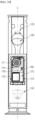
- the cleaner station 100 may include the dust collection unit 170.
- the dust collection unit 170 may be disposed inside the housing 110.
- the dust collection unit 170 may be disposed in the bag accommodation space 115.
- the dust collection unit 170 may be disposed above the coupling unit191 in the direction of gravity.
- a prefilter or the like may be disposed on the flow path, but when dust is filtered using only the prefilter, there is a limitation that the suction force of the dust collection motor is lowered because the prefilter is blocked by a large amount of dust.
- the dust collection unit 170 of the cleaner station 100 of the present invention includes a dust separator 171 to separate and collect dust from the air introduced through the flow path unit 180.
- the dust collection unit 170 may include the dust separator 171, the dust bag 172, the bag support 173, the dust bag cartridge 174, a prefilter 175, and the bonding unit 176.
- the dust separator 171 may separate dust from the air introduced from the dust bin 220.
- the dust separator 171 may be disposed above the dust bag 172, the bag support 173, the dust bag cartridge 174, and the bonding unit 176. That is, the dust bag 172, the bag support 173, the dust bag cartridge 174, and the bonding unit 176 may be disposed under the dust separator 171. The dust separator 171 may come into contact with the dust bag cartridge 174.
- the dust separator 171 may be disposed on the axial line C of the cleaner station 100 in the longitudinal direction.
- the dust separator 171 may include a dust separator case 171a.
- the dust separator case 171a may form the appearance of the dust separator 171.
- a cyclone may be provided inside the dust separator case 171a. That is, a cyclone unit 171b may be disposed inside the dust separator case 171a.
- a dust through pipe 171c may be formed in the dust separator case 171a.
- a flow path through which dust may pass may be formed on a bottom surface of the dust separator case 171a.
- the bottom surface of the dust separator 171 may be formed to be inclined at a predetermined angle with respect to the ground. That is, the bottom surface of the dust separator case 171a may be formed to be inclined at a predetermined angle with respect to the ground.
- a height of the bottom surface of the dust separator 171 from the ground may gradually decrease from one side to the other side. For example, a height of the dust separation case 171a from the ground may gradually decrease rearward from the front end portion into which the dust bag cartridge 174 is inserted.
- a sealer 171d in contact with the dust bag cartridge 174 may be provided on the bottom surface of the dust separator case 171a.
- the sealer 171d may be disposed in a quadrangular shape surrounding the outer periphery of the dust through pipe 171c.
- the dust separator 171 may communicate with the first flow path 181.
- the dust separator 171 may separate dust suctioned therein through the first flow path 181.
- the internal space of the dust separator 171 may communicate with an internal space of the dust bag cartridge 174.
- the internal space of the dust separator 171 may communicate with an internal space of the bag support 173.
- the dust separator 171 may include at least one cyclone unit 171b capable of separating dust by a cyclonic flow. Therefore, the air and dust introduced through the first flow path 181 flow spirally along the inner circumferential surface of the dust separator 171. Therefore, a cyclonic flow may occur in the internal space of the dust separator 171.
- the cyclone unit 171b may have a cylindrical mesh network.
- the axial direction of the mesh network may be disposed parallel to the ground.
- the dust separator 171 may include the dust through pipe 171c that guides the dust separated from the cyclone unit 171b to the dust bag 172.
- the dust through pipe 171c may be formed downward from one side of the cyclone unit 171b in the axial direction. That is, the dust through pipe 171c may be formed under the dust separator case 171a. Therefore, a flow path formed in the dust through pipe 171c may allow the internal spaces of the dust bag cartridge 174 and the bag support 173 to communicate with the cyclone unit 171b.
- the dust separator 171 may further include a secondary cyclone that re-separates dust from the air discharged from the cyclone.
- the secondary cyclone may be located inside the cyclone to minimize a size of the dust separator 171.
- the dust separator 171 is a component that communicates with the first flow path 181 and adopts the principle of a dust collector using a centrifugal force to separate dust flowing into the housing 110 through the dust through hole 121a.
- the dust bag 172 may be disposed inside the housing 110.
- the dust bag 172 may be disposed under the dust separator 171 in the direction of gravity.
- the dust bag 172 may be formed of a non-permeable material.
- the dust bag 172 may include a roll vinyl (not shown). With this configuration, when the dust bag 172 is sealed or bonded, dust or odor collected inside the dust bag 172 can be prevented from leaking out of the dust bag 172.
- the dust bag 172 may be mounted on the housing 110 through the dust bag cartridge 174. As needed, the dust bag 172 may be replaced through the dust bag cartridge 174. That is, the dust collection unit 170 can be defined as a consumable component. A volume of the dust bag 172 may be increased by a suction force (negative pressure) generated when the dust collection motor 191 is operated while mounted in the housing 110.
- the unfolded dust bag 172 may be accommodated inside the bag support 173. That is, the dust bag 172 may be expanded in the bag support 173 when the dust collection motor 191 is operated. In addition, the unfolded dust bag172 may be supported by the bag support 173 to maintain its shape.
- the dust bag 172 may store dust separated by the dust separator 171. An upper region of the dust bag 172 may be cut and bonded by the bonding unit 176. The dust bag 172 may be separated from the bag support 173 while the upper region is cut and bonded.
- the dust bag may be crushed flat while pulled toward the dust collection motor when the dust collection motor is operated. Therefore, it is difficult to collect dust in the dust bag as the internal space of the dust bag narrows when the dust collection motor is operated.
- the dust collection unit 170 of the cleaner station 100 may add the bag support 173 so that the dust bag is stably unfolded.
- the bag support 173 may support the dust bag 172. When the dust bag 172 is expanded, the bag support 173 may accommodate the dust bag 172 therein. The bag support 173 may support the appearance of the expanded dust bag 172.
- the bag support 173 may be disposed under the dust separator 171. With this configuration, the dust separated by the dust separator 171 may be collected into the bag support 173.
- the bag support 173 may be disposed under the dust bag cartridge 174. With this configuration, when the dust bag 172 is expanded downward from the dust bag cartridge 174, at least a portion of the dust bag 172 may be accommodated inside the bag support 173.
- the bag support 173 may be disposed under the bonding unit 176. With this configuration, the expanded dust bag 172 may be bonded and separated by the bonding unit 176 and accommodated in the bag support 173 while falling downward by gravity.
- the bag support 173 may include a support main body 173a and an adsorption hole 173b.
- a space may be formed between a bottom surface of the support main body 173a and the bottom surface of the bag accommodation space 115.
- the space may provide a path along which the suction force of the dust collection motor 191 is transferred.
- the air in the bag accommodation space 115 may be suctioned into the dust collection motor 191 by the suction force of the dust collection motor 191, and a negative pressure for expanding the dust bag 172 may be generated in the bag accommodation space 115.
- the support main body 173a When the dust bag 172 expands, the support main body 173a may be formed to accommodate the dust bag 172 therein.
- the support main body 173a may be formed in a cylindrical shape, a top surface of the support main body 173a may be opened, and at least a portion of the bottom surface of the support main body 173a may be formed in a closed shape.
- the support main body 173a may be formed in a hexahedral shape, the top surface of the support main body 173a may be opened, and a front surface of the support main body 173a may be opened. With this configuration, the dust bag 172 may be removed through the open front surface.
- At least a portion of the dust bag 172 may be disposed above the support main body 173a. In addition, when the dust bag 172 expands, the dust bag 172 expands downward to fill an internal space of the support main body 173a.
- a plurality of adsorption holes 173b may be formed in the support main body 173a.
- the plurality of adsorption holes 173b may be formed along an outer perimetric surface of the support main body 173a.
- at least one adsorption hole 173b may be formed in the bottom surface of the support main body 173a.
- a negative pressure may be applied to the dust bag 172 outward from the support main body 173a, and the dust bag 172 may expand to come into close contact with an inner perimetric surface and bottom surface of the support main body 173a. That is, the dust bag 172 may expand along an internal shape of the bag support 173.
- a uniform negative pressure may be applied to the entire dust bag 172 so that the dust bag 172 may evenly expand to maintain the expanded shape.
- the bag support 173 may be disposed to be drawn out from the housing 110.
- the bag support 173 may be provided in the bag accommodation space 115 formed inside the housing 110.
- the bag support 173 may have a structure for guiding a linear movement of the bag support 173.
- the user may open the side door (not shown) of the cleaner station 100 and then pull the bag support 173 to draw the dust bag 172 out of the housing 110. Therefore, according to the present invention, the user can easily take out the dust bag.
- the dust bag can be easily supplied by the user replacing only the cartridge through the dust bag cartridge 174.
- the dust bag cartridge 174 may be separably coupled to the housing 110 to supply the dust bag 172.
- the dust bag cartridge 174 may be detachably coupled to the housing 110. Specifically, the dust bag cartridge 174 may be detachably coupled to a cartridge coupling space 174e formed between the dust separator 171 and the bonding unit 176.
- the cartridge coupling space 174e may be formed to have different heights in the vertical direction.
- the cartridge coupling space 174e may have a height of the front in which the dust bag cartridge 174 enters the inside of the cleaner station 100 from the outside that is greater than the height of the rear.
- the dust bag cartridge 174 When the user pulls the dust bag cartridge 174 outward from the cleaner station 100 while the dust bag cartridge 174 is coupled to the housing 110, the dust bag cartridge 174 may be separated from the housing 110. With this configuration, the user can easily mount or remove the dust bag cartridge 174 in and from the housing.
- the dust bag cartridge 174 may be provided with the dust bag 172.
- the dust bag 172 may expand toward the bag support 173 according to the operation of the dust collection motor 191.
- some dust bags 172 may be separated from the dust bag cartridge 174 as the dust bag 172 is bonded.
- the dust bag cartridge 174 may be disposed under the dust separator 171.
- the top surface of the dust bag cartridge 174 may come into contact with the bottom surface of the dust separator 171.
- the dust bag cartridge 174 may be disposed above the bonding unit 176.
- the bottom surface of the dust bag cartridge 174 may come into contact with a top surface of the bonding unit 176.
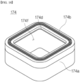
- the dust bag cartridge 174 includes a cartridge case 174a, an upper sealer 174b, and a lower sealer 174c.
- the cartridge case 174a forms the appearance of the dust bag cartridge 174, and the dust bag 172 may be accommodated therein.
- the cartridge case 174a may have an upper case and a lower case coupled to form a space in which the dust bag 172 is accommodated.
- the cartridge case 174a may entirely have a quadrangular pipe shape with the upper case and the lower case coupled (see FIG. 18 ). That is, an inside (central portion) of the cartridge case 174a may be formed with a space 174f in which air may flow. At least a portion of the dust bag 172 may expand through the space 174f.
- a bag supply hole 174d through which the dust bag 172 may be drawn out may be formed in the cartridge case 174a.
- the bag supply hole 174d may be formed in an inner perimetric surface of the cartridge case 174a.
- the cartridge case 174a may be formed to a predetermined height.
- the height of the cartridge case 174a is smaller than a height of a front end of the cartridge coupling space 174e.
- the height of the cartridge case 174a is equal to a height of a rear end of the cartridge coupling space 174e.
- the cartridge case 174a can be easily inserted into the front end of the cartridge coupling space 174e.
- the cartridge case 174a may be supported in contact with the bottom surface of the dust separator 171 and/or the top surface of the bonding unit 176.
- one or more sealers 174b and 174c may be provided in the dust bag cartridge 174 to seal a gap in which dust may scatter.
- the upper sealer 174b may be provided on the top surface of the cartridge case 174a.
- the upper sealer 174b may be disposed in a quadrangular shape surrounding the outer periphery of the space 174f formed at the central portion of the cartridge case 174a.
- the upper sealer 174b can block leakage of foreign substances. With this configuration, foreign substances separated by the dust separator 171 may be collected into the dust bag 172 without leaking externally.
- the lower sealer 174c may be provided on the bottom surface of the cartridge case 174a
- the lower sealer 174c may be disposed in a quadrangular shape surrounding the outer periphery of the space 174f formed at the central portion of the cartridge case 174a.
- the lower sealer 174c and the dust bag cartridge 174 can block leakage of foreign substances. With this configuration, it is possible to prevent foreign substances passing through the dust bag cartridge 174 from leaking between the dust bag cartridge 174 and the bonding unit 176.
- the dust collection unit 170 may further include the prefilter 175.
- the prefilter 175 may be disposed on the second flow path 182 and may separate foreign substances from the air flowing through the second flow path 182.
- the prefilter 175 may be disposed at an inlet side of the second flow path 182 to separate dust and the like contained in the air passing through the dust separator 171. With this configuration, it is possible to prevent foreign substances from flowing into the dust collection motor 191.
- the prefilter 175 may be detachably coupled to the second flow path 182.
- the prefilter 175 may be detachably coupled to the second flow path 182 at the front of the cleaner station 100.
- the dust collection unit 170 may further include the bonding unit 176.
- the bonding unit 176 may be disposed under the dust bag cartridge 174.
- the top surface of the bonding unit 176 may come into contact with the bottom surface of the dust bag cartridge 174. With this configuration, the bonding unit 176 may guide the attachment and detachment of the dust bag cartridge 174.
- the bonding unit 176 may be disposed above the bag support 173. For example, the bottom surface of the bonding unit 176 may come into contact with the top surface of the bag support 173.
- the bonding unit 176 includes a bonding unit case 176a, a sealer 176b, and a cartridge detection sensor 176c.
- the bonding unit case 176a forms the appearance of the bonding unit.
- the bonding unit case 176a may be disposed in the housing 110.
- the bonding unit case 176a may be fixedly coupled to the housing 110.
- the top surface of the bonding unit 176 may be formed to be inclined at a predetermined angle with respect to the ground. That is, the top surface of the bonding unit case 176a may be formed to be inclined at the predetermined angle with respect to the ground. Specifically, a height of the top surface of the bonding unit 176 from the ground may gradually increase from one side to the other side. For example, the height of the top surface of the bonding unit case 176a from the ground may gradually increase rearward from a front end portion into which the dust bag cartridge 174 is inserted.
- a wide inlet of the cartridge coupling space 174e into which the dust bag cartridge 174 is inserted may be formed, and when the dust bag cartridge 174 is completely inserted into the cartridge coupling space 174e, the bonding unit 176 may support the dust bag cartridge 174.
- the sealer 176b in contact with the dust bag cartridge 174 may be disposed on the top surface of the bonding unit case 176a.
- the sealer 176b may be disposed in a quadrangular shape surrounding the outer periphery of the flow path unit 180.
- the sealer 176b may block foreign substances from leaking between the bonding unit 176 and the dust bag cartridge 174.
- the cleaner station 100 further includes the cartridge detection sensor 176c.
- the cartridge detection sensor 176c may be disposed on the top surface of the bonding unit case 176a.
- the top surface of the bonding unit case 176a may include a front top surface, a rear top surface, a left top surface, and a right top surface.
- the front top surface may be a surface disposed at the front of the cleaner station into which the dust bag cartridge is inserted among the top surfaces
- the rear top surface may be a surface disposed at the rear of the cleaner station among the top surfaces
- the left top surface may be a surface disposed at the left of the cleaner station among the top surfaces
- the right top surface may be a surface disposed at the right of the cleaner station among the top surfaces.
- the cartridge detection sensor 176c may be disposed the left top surface or right top surface of the bonding unit case 176a. In addition, the cartridge detection sensor 176c may be disposed at an intermediate position in a front-rear direction of the cleaner station 100. In addition, the cartridge detection sensor 176c may be disposed outside the sealer 176b.
- the cartridge detection sensor 176c may be disposed without interfering with movement paths of the first bonding member (not shown) and the second bonding member (not shown).
- the cartridge detection sensor 176c may detect whether the dust bag cartridge 174 is coupled.
- the cartridge detection sensor 176c may include a contact sensor.
- the cartridge detection sensor 176c may include a micro switch.
- the cartridge detection sensor 176c may come into contact with the dust bag cartridge 174 and detect that the dust bag cartridge 174 has been coupled.
- the dust collection unit 170 may further include a dust amount sensor (not shown).
- the dust amount sensor may measure the amount of dust in the dust bag 172.
- the cleaner station 100 may include the flow path unit 180.
- the flow path unit 180 may connect the cleaner 200 to the dust collection unit 170 and the dust collection motor 191.
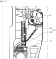
- the flow path unit 180 may include the first flow path 181, the second flow path 182, and the bypass flow path 183.
- the first flow path 181 may connect the dust bin 220 of the cleaner 200 to the dust collection unit 170.
- the first flow path 181 may be disposed at the rear of the coupling surface 121.
- the first flow path 181 may be a space between the dust bin 220 of the cleaner 200 and the dust collection unit 170.
- the first flow path 181 may be a space formed rearward from the dust through hole 121a and may be a flow path formed downward from the dust through hole 121a so that dust and air may flow therethrough.
- the first flow path 181 may include a first region 181a communicating with the internal space of the dust bin 220 and a second region 381b allowing the first region 181a to communicate with the bag accommodation space 115 (or the internal space of the dust collection unit 170) when the cleaner 200 is coupled to the cleaner station 100 to open the dust through hole 121a.
- a direction in which the first region 181a is formed may be disposed substantially parallel to the axial direction (longitudinal direction) of the dust bin.
- a direction in which the second region 181b is formed may be disposed in a direction parallel to the axial line C of the housing 110 in the longitudinal direction.
- the first region 181a may be formed to form a predetermined angle with the second region 181b.
- dust in the dust bin 220 of the cleaner 200 may flow to the dust collection unit 170 through the first flow path 181.
- the second flow path 182 may connect the dust collection unit 170 to the dust suction module 190.
- the second flow path 182 may be a flow path connecting the top of the dust collection unit 170 to the top of the dust suction module 190.
- air passing through the dust collection unit 170 through the second flow path 182 may be guided to the dust collection motor 191.
- the bypass flow path 183 may allow the bag accommodation space 115 to communicate with the internal space of the dust suction module 190.
- the bypass flow path 183 may be a flow path formed along the direction of gravity to connect the bag accommodation space 115 to the dust suction module 190. With this configuration, the bypass flow path 183 may guide the air present in the bag accommodation space 115 to the dust collection motor 191.
- the second flow path 182 and the bypass flow path 183 may communicate with each other to be connected to the dust suction module 190.
- the second flow path 182 may be connected to the bypass flow path 183, and the bypass flow path 183 may be connected to the dust suction module 190.
- the second flow path 182 may be connected to the bypass flow path 183, and the second flow path 182 may be connected to the dust suction module 190. Therefore, the second flow path 182 and the bypass flow path 183 may be connected to the dust collection unit 170 and the dust collection motor 191, respectively.
- the cleaner station 100 may include the dust suction module 190.
- the dust suction module 190 may include the dust collection motor 191.
- the dust collection motor 191 may be disposed under the dust collection unit 170.
- the dust collection motor 191 may generate a suction force in the flow path unit 180. Therefore, the dust collection motor 191 may provide a suction force capable of suctioning the dust in the dust bin 220 of the cleaner 200.
- the dust collection motor 191 may generate the suction force by rotation.
- the dust collection motor 191 may be formed in a shape similar to a cylinder and may generate a suction force while rotating about a rotational axis. In this case, a direction of the rotational axis of the dust collection motor 191 may be perpendicular to the ground.
- FIG. 13 shows a block diagram for describing a control configuration in the cleaner station according to the embodiment of the present invention.
- the cleaner station 100 may further include a controller 400 for controlling the coupling unit 120, the fixing unit 130, the door unit 140, the cover opening unit 150, the dust collection unit 170, the flow path unit 180, and the dust suction module 190.
- the controller 400 may be composed of a printed circuit board and elements mounted on the printed circuit board.
- the coupling sensor 125 When the coupling sensor 125 detects the coupling of the cleaner 200, the coupling sensor 125 may transmit a signal indicating that the cleaner 200 has been coupled to the coupling unit 120. In this case, the controller 400 may receive the signal of the coupling sensor 125 and determine that the cleaner 200 has been coupled to the coupling unit 120.
- the controller 400 may determine that the cleaner 200 has been coupled to the coupling unit 120.
- the controller 400 may fix the cleaner 200 by operating the fixing unit motor 133.
- a fixing detection unit 137 may transmit a signal indicating that the cleaner 200 has been fixed.
- the station controller 400 may receive the signal indicating that the cleaner 200 has been fixed from the fixing detection unit 137 and determine that the cleaner 200 has been fixed. When it is determined that the cleaner 200 has been fixed, the station controller 400 may stop the operation of the fixing unit motor 133.
- the controller 400 may open the door 141 of the cleaner station 100 by operating the door motor 142.
- the door opening and closing detector 144 may transmit a signal indicating that the door 141 has been opened when the door 141 or the door arm 143 reaches the predetermined opening position DP1.
- the controller 400 may receive the signal indicating that the door 141 has been opened from the door opening and closing detector 137 and determine that the door 141 has been opened. When it is determined that the door 141 has been opened, the controller 400 may stop the operation of the door motor 142.
- the controller 400 may close the door 141 by rotating the door motor 142 in the reverse direction.
- the controller 400 may open the discharge cover 222 of the cleaner 200 by operating the cover opening motor 152.
- the cover opening detector 155f may transmit a signal indicating that the discharge cover 222 has been opened when a guide frame 351e reaches a predetermined open position CP1.
- the controller 400 may receive the signal indicating that the discharge cover 222 has been opened from the cover opening detection part 155f and determine that the discharge cover 222 has been opened. When it is determined that the discharge cover 222 has been opened, the controller 400 may stop the operation of the cover opening motor 152.
- the controller 400 may drive the bonding unit 176 to bond the dust bag 172.
- the controller 400 may operate the first bonding member to move in the first direction, and the controller 400 may operate the second bonding member to move in the second direction perpendicular to the first direction.
- the controller 400 may operate the bonding unit 176 after the operation of the dust collection motor 191 is finished.
- the controller 400 may operate the bonding unit 176 when a predetermined time elapses after the operation of the dust collection motor 191 is finished.
- the controller 400 may operate the bonding unit 176 when a predetermined time elapses after the dust collection motor 191 is operated a predetermined number of times.
- the controller 400 may operate the bonding unit 176 every preset cycle, and when the dust collection motor 191 is in operation, the bonding unit 176 may be operated when a predetermined time elapses.
- the controller 400 may operate the bonding unit 176 when the amount of dust measured through the dust amount sensor (not shown) exceeds a predetermined reference.
- the controller 400 may determine whether the dust bag cartridge 174 is mounted through the cartridge detection sensor 176c. When the cartridge detection sensor 176c comes into contact with the dust bag cartridge 174, the cartridge detection sensor 176c may transmit the above contact to the controller 400. In this case, the controller 400 may control the dust collection motor 191 to operate only when the dust bag cartridge 174 is mounted.
- the controller 400 may the dust bin 220 to collect duct only while the dust bag 172 is provided in the cleaner station 100. Therefore, since dust is collected without the dust bag 172, it is possible to prevent foreign substances from contaminating the inside of the cleaner station 100 and causing a failure of the cleaner station 100.
- the controller 400 may suction the dust inside the dust bin 220 by driving the dust collection motor 191.
- the controller 400 may display a dust bin emptying situation and charging situation of the cleaner 200 by operating a display unit 410. For example, in the present embodiment, when the amount of dust measured by the dust amount sensor exceeds a predetermined reference value, the controller 400 may display the fact that the dust bag 172 needs to be replaced on the display unit 410.
- the cleaner station 100 may include the display unit 410.
- the display unit 410 may be disposed not only in the housing 110, but also in a separate display device and provided in a terminal such as a mobile phone.
- the display unit 410 may include at least one of a display panel capable of outputting text and/or graphics, and a speaker capable of outputting voice signals and sounds. A user can easily understand a situation, remaining time, and the like of a current ongoing stroke through the information output through the display unit.
- the cleaner station 100 may include a memory 430.
- the memory 430 may include various data for driving and operating the cleaner station 100.
- the cleaner station 100 may include an input unit 440.
- the input unit 440 generates key input data that the user inputs to control the operation of the cleaner station 100.
- the input unit 440 may be composed of a key pad, a dome switch, a touch pad (static pressure/electrostatic), and the like.
- the touch pad forms a layered structure with the display unit 410, this may be referred to as a touch screen.
- cleaner system 100 cleaner station 110: housing 120: coupling unit 130: fixing unit 140: door unit 150: cover opening unit 170: dust collection unit 171: dust separator 172: dust bag 173: bag support 173a: support main body 173b: adsorption hole 173c: wheel 174: dust bag cartridge 175: prefilter 176: bonding unit 180: flow path unit 181: first flow path 182: second flow path 183: bypass flow path 190: dust suction module 191: dust collection motor 200: cleaner 400: controller
Landscapes
- Engineering & Computer Science (AREA)
- Mechanical Engineering (AREA)
- Robotics (AREA)
- Filters For Electric Vacuum Cleaners (AREA)
- Electric Vacuum Cleaner (AREA)
Abstract
Description
- The present invention relates to a cleaner station, and more specifically, to a cleaner station capable of separating dust contained in the air, collecting the dust in a dust bag, and emptying only the dust bag.
- In general, a cleaner is a home appliance for suctioning small trash or dust in a manner of suctioning air using electricity and filling the same in a dust bin inside a product and is commonly called a vacuum cleaner.
- The vacuum cleaner may be classified into a manual vacuum cleaner for allowing a user to directly perform cleaning while moving the cleaner, and an automatic vacuum cleaner for performing cleaning while traveling by itself. Depending on the type of the vacuum cleaner, the manual vacuum cleaner may be classified into a canister-type vacuum cleaner, an upright vacuum cleaner, a hand vacuum cleaner, a stick-type vacuum cleaner, etc.
- In the past, the canister-type vacuum cleaner was widely used as the household vacuum cleaner, but recently, the hand vacuum cleaner and the stick-type vacuum cleaner, which provide improved convenience of use by integrally providing a dust bin and a cleaner body, are increasingly being used.
- The canister-type vacuum cleaner has a main body and a suction port connected by a rubber hose or a pipe and in some cases, may be used by inserting a brush into the suction port.
- The hand vacuum cleaner is designed to maximize portability and has lightweight and a short length, and thus can have a limited cleaning area. Therefore, the hand vacuum cleaner is used to clean localized sites, such as on a desk, a sofa, or a vehicle interior.
- A user may use the stick-type vacuum cleaner while standing to enable cleaning without bending down. Therefore, it is advantageous for cleaning a wide region while moving. While the hand vacuum cleaner cleans narrow spaces, the stick-type vacuum cleaner may clean wider spaces and clean high places out of reach. Recently, the stick-type vacuum cleaner has been provided in a module type to allow users to actively change a vacuum cleaner type for various purposes.
- In addition, robot cleaners that perform cleaning by themselves without a user's manipulation have been recently used. A robot cleaner may automatically clean an area to be cleaned by suctioning foreign substances, such as dust, from the floor while autonomously traveling in the area to be cleaned.
- However, since conventional handheld vacuum cleaners, stick-type vacuum cleaners, and robot cleaners have a small capacity of dust bins that store collected dust, there is inconvenience that a user needs to empty the dust bin every time.
- In addition, when the dust bin is emptied, there is a problem that dust scatters and has a harmful effect on the user's health.
- In addition, there is a problem of lowering a suction force of the cleaner when the remaining dust in the dust bin is not removed.
- In addition, there is a problem that odor caused by residues occurs when the remaining dust in the dust bin is not removed.
- As the related art document, Korean Patent Registration
KR10-2161708B1 - The related art document includes a station to which a dust bin of a cleaner is coupled, and a dust bag is disposed at a station. In this case, the dust bag is coupled to the inside of a housing of the cleaner along a sliding groove, and an outer surface of the dust bag is formed of a material that may filter dust while passing through air.
- However, in the case of such a permeable or semi-permeable dust bag, there is a problem that the dust inside the dust bag may leak out of the dust bag and the odor also leaks out of the dust bag.
- In addition, as the related art document, the Korea Laid-Open Patent
KR10-2021-0019940A - The related art document includes a cleaner for suctioning and storing dust in the air, and a cleaner station coupled to the dust bin to remove dust stored in the dust bin, in which a dust collection motor for suctioning foreign substances and internal air in the dust bin coupled to the cleaner station and a plastic bag-type dust collection unit.
- However, the cleaner station may be crushed flat as the plastic bag is pulled toward the dust collection motor when the dust collection motor is operated.
- Therefore, the cleaner station cannot easily collect dust in the plastic bag as an internal space of the plastic bag narrows when the dust collection motor is operated.
- In addition, in the cleaner station, there is a problem that some dust flow into the dust collection motor because dust is collected in the plastic bag without being separated from the air.
- Meanwhile, in the case of the cleaner station, it is necessary to have a cartridge capable of replacing a consumable plastic bag.
- In this case, since a plastic bag replacement cartridge is detachably coupled to a housing, there is a limitation that dust contained in the air scatters through a space to which the cartridge is coupled.
- Furthermore, when the cartridge is not accurately mounted in the housing of the station, a large amount of dust may scatter during the dust collection process, causing a failure of internal components of the station.
- Therefore, it is necessary to have a structure capable of preventing the cartridge from being incorrectly mounted and detecting whether the cartridge has been correctly mounted.
- The present invention has been intended to solve the above problems of the conventional cleaner stations and is directed to providing a clean station capable of stably maintaining a shape of a dust bag while dust is collected.
- In addition, the present invention is directed to providing a cleaner station capable of separating dust from air and collecting the dust in a dust bag while the air containing the dust flows toward a dust collection motor.
- In addition, the present invention is directed to providing a cleaner station that does not require a user to directly tie a dust bag.
- In addition, the present invention is directed to providing a cleaner station capable of emptying a dust bin by allowing a user to remove only a dust bag.
- In addition, the present invention is directed to providing a cleaner station capable of supplying a new dust bag when a dust bag is exhausted.
- In addition, the present invention is directed to providing a cleaner station capable of preventing dust from scattering in a cartridge capable of supplying a dust bag.
- In addition, the present invention is directed to providing a cleaner station capable of preventing a cartridge from being mounted incorrectly.
- In addition, the present invention is directed to providing a cleaner station capable of detecting whether a cartridge has been accurately mounted.
- To achieve the above objects, a cleaner station according to the present invention may include a housing, a coupling unit disposed in the housing and including a coupling surface to which at least a portion of a cleaner is coupled, a dust collection unit accommodated inside the housing, disposed under the coupling unit, and collecting dust inside a dust bin of the cleaner, a dust collection motor accommodated inside the housing, disposed under the dust collection unit, and generating a suction force suctioning dust inside the dust bin, and a flow path unit that guides air including the dust inside the dust bin of the cleaner to the dust collection motor.
- In addition, the dust collection unit may include a dust separator that separates dust in the air introduced from the dust bin, a dust bag that stores dust separated by the dust separator, a bag support that accommodates the dust bag, and a dust bag cartridge separably coupled under the dust separator and supplying the dust bag.
- In this case, the dust separator may include a dust separator case having a cyclone provided therein, and a bottom surface of the dust separator case may be formed to be inclined at a predetermined angle with the ground.
- The dust separator may be provided with a sealer provided on a bottom surface of the dust separator case and in contact with the dust bag cartridge.
- The dust collection unit may further include a bonding unit disposed under the dust bag cartridge and bonding the dust bag, and a top surface of the bonding unit may be formed to be inclined at a predetermined angle with the ground.
- The bonding unit may have the top surface provided with a sealer in contact with the dust bag cartridge.
- A height of a bottom surface of the dust separation case from the ground may gradually decrease rearward from the front end portion into which the dust bag cartridge is inserted.
- A height of the top surface of the bonding unit from the ground may gradually increase rearward from a front end portion into which the dust bag cartridge is inserted.
- The dust bag cartridge may include a cartridge case, and an upper sealer provided on a top surface of the cartridge case.
- The dust bag cartridge may include a cartridge case, and a lower sealer provided on a bottom surface of the cartridge case.
- The bonding unit may include a bonding unit case, and a cartridge detection sensor provided on a top surface of the bonding unit case and detecting whether the dust bag cartridge is coupled.
- As described above, according to the cleaner station of the present invention, the shape of the dust bag can be maintained while dust is collected.
- In addition, dust can be separated from air and collected in the dust bag while the air containing the dust flows toward the dust collection motor.
- In addition, the top of the dust bag can be bonded by a bonding unit to seal the dust bag without the user directly tying the dust bag.
- In addition, the user can empty the dust bin by removing only the sealed dust bag.
- In addition, a new dust bag can be supplied when a dust bag is consumed.
- In addition, the cleaner station can prevent dust from scattering in a cartridge capable of supplying a dust bag.
- In addition, the cleaner station can prevent a cartridge from being mounted incorrectly.
- In addition, the cleaner station can detect whether a cartridge has been accurately mounted.
-
-
FIG. 1 is a view for describing a cleaner system according to one embodiment of the present invention. -
FIG. 2 is a schematic view showing a configuration of a cleaner according to one embodiment of the present invention. -
FIG. 3 is a view showing the cleaner ofFIG. 2 viewed at another angle. -
FIG. 4 is a view for describing a bottom surface of a dust bin of the cleaner in the cleaner system according to one embodiment of the present invention. -
FIG. 5 is a view for describing a coupling unit in a cleaner station according to one embodiment of the present invention. -
FIG. 6 is a perspective view for describing a fixing unit in the cleaner station according to one embodiment of the present invention. -
FIGS. 7 and8 are views for describing the relationship between the cleaner and a door unit in the cleaner station according to the embodiment of the present invention. -
FIG. 9 is a view for describing the relationship between the cleaner and a cover opening unit in the cleaner station according to the embodiment of the present invention. -
FIG. 10 is a view for describing the detailed arrangement and configuration of a dust collection unit in the cleaner station according to one embodiment of the present invention. -
FIG. 11 is a view for describing a process in which dust flows through the dust collection unit and a flow path unit in the cleaner station according to one embodiment of the present invention. -
FIG. 12 is a front view for describing the dust collection unit in the cleaner station according to one embodiment of the present invention. -
FIG. 13 is a perspective view for describing a dust separation unit in the cleaner station according to one embodiment of the present invention. -
FIG. 14 is a perspective view for describing a bag support unit in the cleaner station according to one embodiment of the present invention. -
FIG. 15 is a cross-sectional view for describing a dust bag cartridge in the cleaner station according to one embodiment of the present invention. -
FIG. 16 is a view for describing a bottom surface of the dust separator in the cleaner station according to one embodiment of the present invention. -
FIG. 17 is a view for describing a top surface of a bonding unit in the cleaner station according to one embodiment of the present invention. -
FIG. 18 is a perspective view for describing a dust bag cartridge in the cleaner station according to one embodiment of the present invention. -
FIG. 19 is a perspective view ofFIG. 18 in another direction. -
FIG. 20 is a schematic view for describing a state before the dust bag cartridge is inserted in the cleaner station according to one embodiment of the present invention. -
FIG. 21 is a schematic view for describing a state in which the dust bag cartridge is inserted and sealed in the cleaner station according to one embodiment of the present invention. -
FIG. 22 is a view for describing a configuration of the bonding unit in the cleaner station according to one embodiment of the present invention. -
FIG. 23 is a view for describing the flow path unit and a prefilter in the cleaner station according to one embodiment of the present invention. -
FIG. 24 is a block diagram for describing a control configuration of the cleaner station according to one embodiment of the present invention. - Hereinafter, exemplary embodiments of the present invention will be described in detail with reference to the accompanying drawings.
- Since the present invention may have various changes and various embodiments, specific embodiments are shown in the accompanying drawings and specifically described in the detail descriptions. This is not intended to limit the present invention to specific embodiments and should be construed to include all modifications, equivalents, and substitutes included in the spirit and technical scope of the present invention.
- The terms used in the present application are only used to describe specific embodiments and are not intended to limit the present invention. The singular expression includes the plural expression unless the context clearly dictates otherwise.
- Unless defined otherwise, all terms used herein, including technical or scientific terms, have the same meaning as commonly understood by those skilled in the art to which the present invention pertains. The terms defined in a generally used dictionary can be construed as meanings that match with the meanings of the terms from the context of the related technology and are not construed as an ideal or excessively formal meaning unless clearly defined in the present application.
-
FIG. 1 shows a view for describing a cleaner system according to one embodiment of the present invention. - Referring to
FIG. 1 , acleaner system 1 according to one embodiment of the present specification may include a cleaner 200 and acleaner station 100. - The
cleaner system 1 may include thecleaner station 100. The cleaner 200 may be coupled to thecleaner station 100. The cleaner 200 may be coupled to a side surface of thecleaner station 100. Thecleaner station 100 may remove dust of adust bin 220 of the cleaner 200. -
FIG. 2 shows a schematic view showing a configuration of a cleaner according to one embodiment of the present invention,FIG. 3 shows a view showing the cleaner ofFIG. 2 viewed at another angle, andFIG. 4 shows a view for describing a bottom surface of a dust bin of the cleaner in the cleaner system according to one embodiment of the present invention. - First, a structure of the cleaner 200 will be described with reference to
FIGS. 2 to 4 . - The cleaner 200 may be a cleaner that is manually manipulated by a user. For example, the cleaner 200 may be a hand cleaner or a stick-type cleaner.
- The cleaner 200 may be caught on the
cleaner station 100. The cleaner 200 may be supported by thecleaner station 100. The cleaner 200 may be coupled to thecleaner station 100. - Meanwhile, in one embodiment of the present invention, a direction of the cleaner 200 can be defined based on when bottom surfaces (lower surfaces) of the
dust bin 220 and abattery housing 230 are placed on the ground. - In this case, the front may be a direction in which a
suction unit 212 is disposed with respect to a suction motor 214, and the rear may be a direction in which ahandle 216 is disposed with respect to to the suction motor 214. In addition, a direction located at the right may be referred to as a right side, and a direction located at the left may be referred to as a left side with respect to when viewing thesuction unit 212 from the suction motor 214. In addition, in one embodiment of the present invention, top and bottom can be defined in a direction perpendicular to the ground with respect to when the bottom surfaces (lower surfaces) of thedust bin 220 and thebattery housing 230 are placed on the ground. - The cleaner 200 may include a main body 210. The main body 210 may include a
main body housing 211, thesuction unit 212, adust separator 213, a suction motor 214, an air discharge cover 215, thehandle 216, and amanipulation unit 218. - The
main body housing 211 may form the appearance of the cleaner 200. Themain body housing 211 may provide a space in which the suction motor 214 and a filter (not shown) may be accommodated. Themain body housing 211 may be formed in substantially a cylindrical shape. - The
suction unit 212 may protrude outward from themain body housing 211. As an example, thesuction unit 212 may be formed in a cylindrical shape with an open interior. Thesuction unit 212 may be coupled to anextension pipe 250. Thesuction unit 212 may provide a flow path (hereinafter referred to as "suction flow path") through which air containing dust may flow. - Meanwhile, in the present embodiment, a virtual line passing through the inside of the
suction unit 212 formed in a cylindrical shape may be formed. - The
dust separator 213 may communicate with thesuction unit 212. Thedust separator 213 may separate dust suctioned therein through thesuction unit 212. An internal space of thedust separator 213 may communicate with an internal space of thedust bin 220. - For example, the
dust separator 213 may have at least one cyclone unit capable of separating dust by a cyclonic flow. In addition, the internal space of thedust separator 213 may communicate with the suction flow path. Therefore, the air and dust suctioned through thesuction unit 212 spirally flow along an inner circumferential surface of thedust separator 213. Therefore, a cyclonic flow may occur in the internal space of thedust separator 213. - The
dust separator 213 is a component that communicates with thesuction unit 212 and adopts the principle of a dust collector using a centrifugal force to separate dust suctioned into the main body 210 through thesuction unit 212. - The
dust separator 213 may further include a secondary cyclone that re-separates dust from the air discharged from the cyclone. In this case, the secondary cyclone may be located inside the cyclone to minimize a size of the dust separator. The secondary cyclone may include a plurality of cyclone bodies disposed in parallel. The air discharged from the cyclone may be partitioned into the plurality of cyclone bodies and may pass through the same. - In this case, an axis of the cyclonic flow of the secondary cyclone may extend vertically, and an axis of the cyclonic flow of the cyclone and the axis of the cyclonic flow of the secondary cyclone may be coaxial vertically and may be collectively referred to as an axis of the cyclonic flow of the
dust separator 213. - The suction motor 214 may generate a suction force of suctioning air. The suction motor 214 may be accommodated in the
main body housing 211. The suction motor 214 may generate a suction force by rotation. As an example, the suction motor 214 may be provided in a shape similar to a cylindrical shape. - Meanwhile, in the present embodiment, a virtual suction motor axial line extending a rotational axis of the suction motor 214 may be formed.
- The air discharge cover 215 may be disposed at one side of the
main body housing 211 in the axial direction. The air discharge cover 215 may accommodate a filter for filtering air. For example, the air discharge cover 215 may accommodate a HEPA filter. - An air outlet through which the air suctioned by the suction force of the suction motor 214 is discharged may be formed on the air discharge cover 215.
- A flow guide may be disposed on the air discharge cover 215. The flow guide may guide a flow of the air discharged through the air outlet.
- The
handle 216 may be gripped by a user. Thehandle 216 may be disposed behind the suction motor 214. As an example, thehandle 216 may be formed in a shape similar to a cylindrical shape. Alternatively, thehandle 216 may be formed in a curved cylindrical shape. Thehandle 216 may be disposed at a predetermined angle with themain body housing 211, the suction motor 214, or thedust separator 213. - The
handle 216 may include agrip portion 216a formed in a pillar shape to allow the user to grip the same, afirst extension 216b connected to one end portion of thegrip portion 216a in a longitudinal direction (axial direction) and formed to extend toward the suction motor 214, and asecond extension 216c connected to the other end portion of thefirst extension 216b and thegrip portion 216a in the longitudinal direction (axial direction) and formed to extend toward thedust bin 220. - Meanwhile, in the present embodiment, a virtual grip portion penetration line formed to extend in the longitudinal direction of the
grip portion 216a (axial direction of a pillar) and penetrating the grip portion may be formed. - As an example, the grip portion penetration line may be a virtual line formed inside the
cylindrical handle 216 and may be a virtual line formed parallel to at least a portion of an outer surface (outer perimetric surface) of thegrip portion 216a. - An upper surface of the
handle 216 may form a partial appearance of an upper surface of the cleaner 200. Therefore, when the user grips thehandle 216, one component of the cleaner 200 can be prevented from coming into contact with the user's arm. - The first extension may extend from the
grip portion 216a toward themain body housing 211 or the suction motor 214. At least a portion of the first extension may extend in a horizontal direction. - The second extension may extend from the
grip portion 216a to thedust bin 220. At least a portion of the second extension may extend in the horizontal direction. - The
manipulation unit 218 may be disposed on thehandle 216. Themanipulation unit 218 may be disposed on an inclined surface formed on an upper region of thehandle 216. The user may input an operation or stop command of the cleaner 200 through themanipulation unit 218. - The cleaner 200 may include the
dust bin 220. Thedust bin 220 may communicate with thedust separator 213. Thedust bin 220 may store the dust separated by thedust separator 213. - The
dust bin 220 may include a dust binmain body 221, adischarge cover 222, a dustbin compression lever 223, and a compression member (not shown). - The dust bin
main body 221 may provide a space in which the dust separated by thedust separator 213 may be stored. As an example, the dust binmain body 221 may be formed in a shape similar to a cylindrical shape. - Meanwhile, in the present specification, a virtual dust bin penetration line, which penetrates the inside (internal space) of the dust bin
main body 221 and formed to extend in the longitudinal direction (which is an axial direction in the cylindrical dust bin main body 221) of the dust binmain body 221, may be formed. - A portion of a bottom surface (floor surface) of the dust bin
main body 221 may be open. In addition, alower surface extension 221a may be formed on the bottom surface (floor surface) of the dust binmain body 221. Thelower surface extension 221a may be formed to block a portion of the bottom surface of the dust binmain body 221. - The
dust bin 220 may include thedischarge cover 222. Thedischarge cover 222 may be disposed on the bottom surface of thedust bin 220. - The
discharge cover 222 may be provided to open and close one end portion of the dust binmain body 221 in the longitudinal direction. Specifically, thedischarge cover 222 may selectively open and close a downward open lower portion of thedust bin 220. - The
discharge cover 222 may include a covermain body 222a and ahinge unit 222b. The covermain body 222a may be formed to block a portion of the bottom surface of the dust binmain body 221. The covermain body 222a may rotate downward with respect to thehinge unit 222b. Thehinge unit 222b may be disposed adjacent to thebattery housing 230. Thehinge unit 222b may be provided with atorsion spring 222d. Therefore, when thedischarge cover 222 is separated from the dust binmain body 221, the covermain body 222a may be supported while rotated about thehinge unit 222b at a predetermined angle or more in the dust binmain body 221 by an elastic force of thetorsion spring 222d. - The
discharge cover 222 may be coupled to thedust bin 220 through hook coupling. Meanwhile, thedischarge cover 222 may be separated from thedust bin 220 through acoupling lever 222c. Thecoupling lever 222c may be disposed at the front of the dust bin. Specifically, thecoupling lever 222c may be disposed on a front outer surface of thedust bin 220. When an external force is applied, thecoupling lever 222c may elastically deform a hook extending from the covermain body 222a to release hook coupling between the covermain body 222a and the dust binmain body 221. - When the
discharge cover 222 is closed, the bottom surface of thedust bin 220 may be blocked (sealed) by thedischarge cover 222 and thelower surface extension 221a. - The
dust bin 220 may include the dust bin compression lever 223 (seeFIG. 8 ). The dustbin compression lever 223 may be disposed outside thedust bin 220 or thedust separator 213. The dustbin compression lever 223 may be disposed to move upward and downward outside thedust bin 220 or thedust separator 213. The dustbin compression lever 223 may be connected to the compression member (not shown). When the dustbin compression lever 223 is moved downward by an external force, the compression member (not shown) may also move downward. Therefore, user convenience can be provided. The compression member (not shown) and the dustbin compression lever 223 may be returned to original positions by an elastic member (not shown). Specifically, when the external force applied to the dustbin compression lever 223 is removed, the elastic member may move the dustbin compression lever 223 and the compression member (not shown) upward. - The compression member (not shown) may be disposed inside the dust bin
main body 221. The compression member may move in an internal space of the dust binmain body 221. Specifically, the compression member may move upward and downward in the dust binmain body 221. Therefore, the compression member may compress the dust in the dust binmain body 221 downward. In addition, when thedischarge cover 222 is separated from the dust binmain body 221 and the lower portion of thedust bin 220 is opened, the compression member may move from the upper portion to the lower portion of thedust bin 220 to remove foreign substances such as the remaining dust in thedust bin 220. Therefore, it is possible to increase the suction force of the cleaner by preventing the remaining dust from remaining in thedust bin 220. In addition, bad odors generated by the residue can be removed by preventing the remaining dust from remaining in thedust bin 220. - The cleaner 200 may include the
battery housing 230. Abattery 240 may be accommodated in thebattery housing 230. Thebattery housing 230 may be disposed under thehandle 216. As an example, thebattery housing 230 may have a hexahedral shape with an open lower portion. A rear surface of thebattery housing 230 may be connected to thehandle 216. - The
battery housing 230 may include an accommodation portion that is opened downward. Thebattery 240 may be detachably attached through the accommodation portion of thebattery housing 220. - The cleaner 200 may include the
battery 240. - For example, the
battery 240 may be detachably coupled to the cleaner 200. Thebattery 240 may be detachably coupled to thebattery housing 230. As an example, thebattery 240 may be inserted into thebattery housing 230 from the bottom of thebattery housing 230. With this configuration, it is possible to improve the portability of the cleaner 200. - Alternatively, the
battery 240 may be provided integrally inside thebattery housing 230. In this case, a lower surface of thebattery 240 is not externally exposed. - The
battery 240 may supply power to the suction motor 214 of the cleaner 200. Thebattery 240 may be disposed under thehandle 216. Thebattery 240 may be disposed behind thedust bin 220. - According to an embodiment, when the
battery 240 is coupled to thebattery housing 230, the lower surface of thebattery 240 may be externally exposed. Since thebattery 240 may be placed on the floor when the cleaner 200 is placed on the floor, thebattery 240 may be immediately separated from thebattery housing 230. In addition, since the lower surface of thebattery 240 is externally exposed and come into direct contact with the external air of thebattery 240, it is possible to improve cooling performance of thebattery 240. - Meanwhile, when the
battery 240 is integrally fixed to thebattery housing 230, the structure for attaching and detaching thebattery 240 and thebattery housing 230 can be smaller, thereby reducing the overall size of the cleaner 200 and achieving lightweight. - The cleaner 200 may include the
extension pipe 250. Theextension pipe 250 may communicate with acleaning module 260. Theextension pipe 250 may communicate with the main body 210. Theextension pipe 250 may communicate with the suction unit 214 of the main body 210. Theextension pipe 250 may be formed in a long cylindrical shape. - The main body 210 may be connected to the
extension pipe 250. The main body 210 may be connected to thecleaning module 260 through theextension pipe 250. The main body 210 may generate the suction force through the suction motor 214 and provide the suction force to thecleaning module 260 through theextension pipe 250. External dust may flow into the main body 210 through thecleaning module 260 and theextension pipe 250. - The cleaner 200 may include the
cleaning module 260. Thecleaning module 260 may communicate with theextension pipe 250. Therefore, external air may pass through thecleaning module 260 and theextension pipe 250 and flow into the main body 210 of the cleaner 200 by the suction force generated from the main body 210 of the cleaner 200. - Dust in the
dust bin 220 of the cleaner 200 may be collected in thedust collection unit 170 of thecleaner station 100 by gravity and the suction force of adust collection motor 191. Therefore, since the dust in the dust bin can be removed without the user's separate manipulation, user convenience can be provided. In addition, it is possible to eliminate the user's inconvenience having to empty the dust bin every time. In addition, it is possible to prevent the scattering of dust when the user empties the dust bin. - The cleaner 200 may be coupled to a side surface of a
housing 110. Specifically, the main body 210 of the cleaner 200 may be caught on acoupling unit 120. More specifically, thedust bin 220 and thebattery housing 230 of the cleaner 200 may be coupled to acoupling surface 121, an outer circumferential surface of the dust binmain body 221 may be coupled to a dustbin guide surface 122, and thesuction unit 212 may be coupled to a suctionunit guide surface 126 of thecoupling unit 120. In this case, a central axis of thedust bin 220 may be disposed in a direction parallel to the ground, and theextension pipe 250 may be disposed in a direction perpendicular to the ground. -
FIG. 5 shows a view for describing a coupling part in a cleaner station according to one embodiment of the present invention,FIG. 6 shows a perspective view for describing a fixing unit in the cleaner station according to one embodiment of the present invention,FIGS. 7 and8 show views for describing the relationship between the cleaner and a door unit in the cleaner station according to the embodiment of the present invention, andFIG. 9 shows a view for describing the relationship between the cleaner and a cover opening unit in the cleaner station according to the embodiment of the present invention. - The
cleaner station 100 of the present invention will be described with reference toFIGS. 5 to 9 as follows. - The cleaner 200 may be coupled to the
cleaner station 100. Specifically, the main body of the cleaner 200 may be coupled to the side surface of thecleaner station 100. Thecleaner station 100 may remove dust of thedust bin 220 of the cleaner 200. - The
cleaner station 100 may include thehousing 110. Thehousing 110 may form the appearance of thecleaner station 100. Specifically, thehousing 110 may be formed in a pillar shape including at least one outer wall surface. As an example, thehousing 110 may be formed in a shape similar to a quadrangular pillar. - The
housing 110 may have a space in which thedust collection unit 170 for storing dust therein and thedust suction module 190 for generating a flow force of collecting dust into thedust collection unit 170 may be accommodated. - The
housing 110 may include afloor surface 111, anouter wall surface 112, and anupper surface 113. - The
floor surface 111 may support a bottom of thedust suction module 190 in a direction of gravity. That is, thefloor surface 111 may support the bottom of thedust collection motor 191 of thedust suction module 190. - In this case, the
floor surface 111 may be disposed toward the ground. Thefloor surface 111 may be not only disposed parallel to the ground, but also disposed to be inclined at a predetermined angle with the ground. With this configuration, there is an advantage that thedust collection motor 191 can be stably supported and the overall weight can be balanced even when the cleaner 200 is coupled. - Meanwhile, according to an embodiment, the
floor surface 111 may further include a ground support 311a that increases an area in contact with the ground to prevent thecleaner station 100 from falling and maintain balance. As an example, the ground support 311a may be in the form of a plate extending from thefloor surface 111, and one or more frames may be formed to protrude and extend from thefloor surface 111 in the direction of the ground. - The
outer wall surface 112 may be a surface formed in the direction of gravity and may be a surface connected to thefloor surface 111. For example, theouter wall surface 112 may be a surface connected perpendicular to thefloor surface 111. In another embodiment, theouter wall surface 112 may be disposed to be inclined at a predetermined angle with thefloor surface 111. - The
outer wall surface 112 may include at least one surface. As an example, theouter wall surface 112 may include a firstouter wall surface 112a, a second outer wall surface 112b, a thirdouter wall surface 112c, and a fourth outer wall surface 112d. - In this case, in the present embodiment, the first
outer wall surface 112a may be disposed on a front surface of thecleaner station 100. Here, the front surface may be a surface on which the cleaner 200 is exposed while the cleaner 200 is coupled to thecleaner station 100. Therefore, the firstouter wall surface 112a may form the appearance of the front surface of thecleaner station 100. - Meanwhile, for understanding of the present embodiment, directions are defined as follows. In the present embodiment, directions can be defined in a state in which the cleaner 200 is caught on the
cleaner station 100. - When the cleaner 200 is caught on the
cleaner station 100, a direction in which the cleaner 200 is exposed externally from thecleaner station 100 may be referred to as the front. - From another perspective, when the cleaner 200 is caught on the
cleaner station 100, a direction in which the suction motor 214 of the cleaner 200 is disposed may be referred to as the front. In addition, a direction opposite to the direction in which the suction motor 214 is disposed in thecleaner station 100 may be referred to as the rear. - In addition, a surface in a direction facing the front surface with respect to the internal space of the
housing 110 may be referred to as the rear surface of thecleaner station 100. Therefore, the rear surface may refer to a direction in which the second outer wall surface 112b is formed. - In addition, when viewing the front surface with respect to the internal space of the
housing 110, a surface at the left may be referred to as a left surface, and a surface at the right may be referred to as a right surface. Therefore, the left surface may refer to a direction in which the thirdouter wall surface 112c is formed, and the right surface may refer to the direction in which the fourth outer wall surface 112d is formed. - The first
outer wall surface 112a may be formed not only in a flat shape, but also entirely in a curved shape, and a portion thereof may be formed to include a curved surface. - The
coupling unit 120 may be disposed on the firstouter wall surface 112a. With this configuration, the cleaner 200 may be coupled to thecleaner station 100 and supported by thecleaner station 100. A detailed configuration of thecoupling unit 120 will be described below. - Meanwhile, a structure for holding any type of
cleaning module 260 used in the cleaner 200 may be added to the firstouter wall surface 112a. - In the present embodiment, the second outer wall surface 112b may be a surface facing the first
outer wall surface 112a. That is, the second outer wall surface 112b may be disposed on the rear surface of thecleaner station 100. The second outer wall surface 112b may form the appearance of the rear surface of thecleaner station 100. - In the present embodiment, the third
outer wall surface 112c and the fourth outer wall surface 112d may be surfaces that connect the firstouter wall surface 112a with the second outer wall surface 112b. In this case, the thirdouter wall surface 112c may be disposed on the left surface of thecleaner station 100, and the fourth outer wall surface 112d may be disposed on the right surface of thecleaner station 100. Alternatively, the thirdouter wall surface 112c may be disposed on the right surface of thecleaner station 100, and the fourth outer wall surface 112d may be disposed on the left surface of thecleaner station 100. - The third
outer wall surface 112c or the fourth outer wall surface 112d may be formed not only in a flat shape, but also entirely in a curved shape, and portions thereof may be formed to include a curved surface. - Meanwhile, a structure for holding any type of cleaning module 290 used in the cleaner 200 may be added to the third
outer wall surface 112c or the fourth outer wall surface 112d. - The
upper surface 113 may form the appearance of the top of the cleaner station. That is, theupper surface 113 may be a surface that is disposed at the uppermost side of the cleaner station in the direction of gravity and exposed externally. - For reference, in the present embodiment, top and bottom may be top and bottom, respectively, in the direction of gravity (direction perpendicular to the ground) in a state in which the
cleaner station 100 is installed on the ground. - In this case, the
upper surface 113 may be disposed not only parallel to the ground, but also to be inclined at a predetermined angle with the ground. - A display unit may be disposed on the
upper surface 113. As an example, the display unit may display the state of thecleaner station 100 and the state of the cleaner 200 and also display pieces of information such as a cleaning progress situation and a map of a cleaning area. - Meanwhile, according to an embodiment, the
upper surface 113 may be provided separately from theouter wall surface 112. In this case, when theupper surface 113 is separated, a battery separated from the cleaner 200 may be accommodated in the internal space surrounded by theouter wall surface 112 and provided with a terminal (not shown) for charging the separated battery. - Meanwhile, a
bag accommodation space 115 may be formed inside thehousing 110. Thebag accommodation space 115 may be disposed under thecoupling unit 120 in the direction of gravity and disposed above thedust suction module 190 in the direction of gravity. - The
dust collection unit 170 may be provided in thebag accommodation space 115. Specifically, abag support 173 described below may be accommodated to be accessible in thebag accommodation space 115. In addition, adust bag cartridge 174 described below may be detachably coupled to thebag accommodation space 115. In addition, abonding unit 176 described below may be mounted in thebag accommodation space 115. Thebag accommodation space 115 may communicate with afirst flow path 181, asecond flow path 182, and abypass flow path 183, which will be described below. With this configuration, thebag accommodation space 115 may provide a space in which air and dust introduced from thedust bin 220 may flow and may be collected in adust bag 172. - In the present invention, the cleaner 200 may be mounted on the
outer wall surface 112 of thecleaner station 100. As an example, thedust bin 220 and thebattery housing 230 of the cleaner 200 may be coupled to thecoupling surface 121 of thecleaner station 100. That is, the cleaner 200 may be caught on the firstouter wall surface 112a. - In this case, an axial line of the suction motor 214 may be formed perpendicular to the first
outer wall surface 112a. That is, the axial line of the suction motor 214 may be formed parallel to the ground. - A virtual line penetrating the
dust bin 220 may be formed perpendicular to the firstouter wall surface 112a. - An axial line C of the
housing 110 in the longitudinal direction may be formed perpendicular to the ground. The axial line C of thehousing 110 in the longitudinal direction may be formed parallel to at least one of the firstouter wall surface 112a, the second outer wall surface 112b, the thirdouter wall surface 112c, and the fourth outer wall surface 112d. - When the cleaner 200 is coupled to the
cleaner station 100, an axial line of the suction motor 214 may intersect an axial line of thecleaner station 100 in the longitudinal direction. That is, the rotational axis of the suction motor 214 may intersect the axis of thecleaner station 100 in the longitudinal direction. - In addition, when the cleaner 200 is coupled to the
cleaner station 100, thebattery 240 may be disposed at a farther distance from the ground than the rotational axis of the suction motor 214. With this configuration, the cleaner 200 may be stably supported by thecleaner station 100. - When the cleaner 200 is coupled to the
cleaner station 100, a virtual line penetrating thedust bin 220 may intersect the axis of thecleaner station 100 in the longitudinal direction. That is, the axis of thedust bin 220 in the longitudinal direction may intersect the axis of thecleaner station 100 in the longitudinal direction. In this case, an intersection of the axis of thedust bin 220 and the axis of thecleaner station 100 in the longitudinal direction may be located inside thehousing 110, and more specifically, located inside the flow path unit 180. - Meanwhile, when the cleaner 200 is coupled to the
cleaner station 100, thehandle 216 may be disposed at a farther distance from the ground than the virtual line penetrating thedust bin 220. With this configuration, when the user grips thehandle 216, it is possible to provide convenience to couple or separate the cleaner 200 to and from thecleaner station 100 with only a user's simple operation of moving the cleaner 200 in a direction parallel to the ground. - The
coupling unit 120 of thecleaner station 100 of the present invention will be described with reference toFIG. 5 as follows. - The
cleaner station 100 may include thecoupling unit 120 to which the cleaner 200 is coupled. Specifically, thecoupling unit 120 may be disposed on the firstouter wall surface 112a, and the main body 210, thedust bin 220, and thebattery housing 230 of the cleaner 200 may be coupled. - The
coupling unit 120 may include thecoupling surface 121. Thecoupling surface 121 may be disposed on a side surface of thehousing 110. As an example, thecoupling surface 121 may be a surface formed in a groove shape that is concave from the firstouter wall surface 112a to the inside of thecleaner station 100. That is, thecoupling surface 121 may be a surface formed by forming a step with the firstouter wall surface 112a. - The cleaner 200 may be coupled to the
coupling surface 121. As an example, thecoupling surface 121 may come into contact with the bottom surfaces of thedust bin 220 and thebattery housing 230 of the cleaner 200. Here, the bottom surface may be a surface facing the ground when the user uses the cleaner 200 or places the cleaner 200 on the ground. - As an example, an angle formed by the
coupling surface 121 and the ground may be a right angle. Therefore, when the cleaner 200 is coupled to thecoupling surface 121, it is possible to minimize a space of thecleaner station 100. - As another example, the
coupling surface 121 may be disposed to be inclined at a predetermined angle with the ground. Therefore, when the cleaner 200 is coupled to thecoupling surface 121, thecleaner station 100 can be stably supported. - A dust through
hole 121a may be formed in thecoupling surface 121 to allow external air of thehousing 110 to flow therein. The dust throughhole 121a may be formed in a hole shape corresponding to the shape of thedust bin 220 so that the dust in thedust bin 220 flows into thedust collection unit 170. The dust throughhole 121a may be formed to correspond to the shape of thedischarge cover 222 of thedust bin 220. The dust throughhole 121a may be formed to communicate with the flow path unit 180 described below. - The
coupling unit 120 may include the dustbin guide surface 122. The dustbin guide surface 122 may be disposed on the firstouter wall surface 112a. The dustbin guide surface 122 may be connected to the firstouter wall surface 112a. In addition, the dustbin guide surface 122 may be connected to thecoupling surface 121. - The dust
bin guide surface 122 may be formed in a shape corresponding to the outer surface of thedust bin 220. The front outer surface of thedust bin 220 may be coupled to the dustbin guide surface 122. Therefore, the convenience of coupling the cleaner 200 to thecoupling surface 121 can be provided. - Meanwhile, a
protrusion movement hole 122a may be formed in the dustbin guide surface 122, and apush protrusion 151 described below may move linearly along theprotrusion movement hole 122a. In addition, agear box 155 for accommodating a gear of thecover opening unit 150 described below and the like may be provided under the dustbin guide surface 122 in the direction of gravity. In this case, aguide space 122b in which thepush protrusion 151 may move may be formed between a bottom surface of the dustbin guide surface 122 and a top surface of thegear box 155. In addition, theguide space 122b may communicate with thefirst flow path 181 through abypass hole 122c. That is, theprotrusion movement hole 122a, theguide space 122b, thebypass hole 122c, and thefirst flow path 181 may form one flow path. With this configuration, when thedust collection motor 191 is operated while thedust bin 220 is coupled to thecoupling unit 120, there is an advantage that dust and the like remaining in thedust bin 220 and the dustbin guide surface 122 may be suctioned through the flow path. - The
coupling unit 120 may include aguide protrusion 123. Theguide protrusion 123 may be disposed on thecoupling surface 121. Theguide protrusion 123 may protrude upward from thecoupling surface 121. Twoguide protrusions 123 may be disposed to be spaced apart from each other. A distance between the twoguide protrusions 123 spaced apart from each other may correspond to a width of thebattery housing 230 of the cleaner 200. Therefore, the convenience of coupling the cleaner 200 to thecoupling surface 121 can be provided. - The
coupling unit 120 may include a couplingunit side wall 124. The couplingunit side wall 124 may be a wall surface disposed on both side surfaces of thecoupling surface 121 and connected perpendicular to thecoupling surface 121. The couplingunit side wall 124 may be connected to the firstouter wall surface 112a. In addition, the couplingunit side wall 124 may form a surface connected to the dustbin guide surface 122. Therefore, the cleaner 200 can be stably accommodated. - The
coupling unit 120 may include acoupling sensor 125. Thecoupling sensor 125 may detect whether the cleaner 200 is coupled to thecoupling unit 120. - The
coupling sensor 125 may include a contact sensor. As an example, thecoupling sensor 125 may include a micro switch. In this case, thecoupling sensor 125 may be disposed on theguide protrusion 123. Therefore, when thebattery housing 230 or thebattery 240 of the cleaner 200 is coupled between the pair ofguide protrusions 123, thecleanser 200 may come into contact with thecoupling sensor 125, and thecoupling sensor 125 may detect that the cleaner 200 has been coupled. - Meanwhile, the
coupling sensor 125 may include a non-contact sensor. As an example, thecoupling sensor 125 may include an infrared (IR) sensor. In this case, thecoupling sensor 125 may be disposed on the couplingunit side wall 124. Therefore, when thedust bin 220 or the main body 210 of the cleaner 200 reaches thecoupling surface 121 through the couplingunit side wall 124, thecoupling sensor 125 may detect the presence of thedust bin 220 or the main body 210. - In a state in which the cleaner 200 is coupled to the
cleaner station 100, thecoupling sensor 125 may face thedust bin 220 or thebattery housing 230 of the cleaner 200. - The
coupling sensor 125 may be a member of determining whether power is applied to thebattery 240 of the cleaner 200 and whether the cleaner 200 has been coupled. - The
coupling unit 120 may include a suctionunit guide surface 126. The suctionunit guide surface 126 may be disposed on the firstouter wall surface 112a. The suctionunit guide surface 126 may be connected to the dustbin guide surface 122. Thesuction unit 212 may be coupled to the suctionunit guide surface 126. A shape of the suctionunit guide surface 126 may be formed in a shape corresponding to the shape of thesuction unit 212. - The
coupling unit 120 may further include a fixingmember entrance hole 127. The fixingmember entrance hole 127 may be formed in the form of a long hole along the couplingunit side wall 124 so that the fixingmember 131 enters and exits. - With this configuration, when the user couples the cleaner 200 to the
coupling unit 120 of thecleaner station 100, the main body 210 of the cleaner 200 may be stably disposed on thecoupling unit 120 by the dustbin guide surface 122, theguide protrusion 123, and the suctionunit guide surface 126. Therefore, convenience of coupling thedust bin 220 and thebattery housing 230 of the cleaner 200 to thecoupling surface 121 can be provided. - Meanwhile, the
cleaner station 100 may further include acharging unit 128. The chargingunit 128 may be disposed on thecoupling unit 120. The chargingunit 128 may be electrically connected to the cleaner 200 coupled to thecoupling unit 120. The chargingunit 128 may supply power to the battery of the cleaner 200 coupled to thecoupling unit 120. - In addition, the
cleaner station 100 may further include a side door (not shown). The side door may be disposed in thehousing 110. The side door may selectively expose thedust collection unit 170 externally. Therefore, the user can easily remove thedust bag 172 from thecleaner station 100. - A fixing
unit 130 according to the present invention will be described with reference toFIG. 6 as follows. - The
cleaner station 100 according to the present invention may include the fixingunit 130. The fixingunit 130 may be disposed on the couplingunit side wall 124. In addition, the fixingunit 130 may be disposed on the rear surface of thecoupling surface 121. The fixingunit 130 may fix the cleaner 200 coupled to thecoupling surface 121. Specifically, the fixingunit 130 may fix thedust bin 220 and thebattery housing 230 of the cleaner 200 coupled to thecoupling surface 121. - The fixing
unit 130 may include a fixingmember 131 for fixing thedust bin 220 and thebattery housing 230 of the cleaner 200, and a fixingunit motor 133 for driving the fixingmember 131. In addition, the fixingunit 130 may further include a fixingunit link 135 for transmitting the power of the fixingunit motor 133 to the fixingmember 131. - The fixing
member 131 may be disposed on the couplingunit side wall 124 and may be provided to reciprocate on the couplingunit side wall 124 to fix thedust bin 220. Specifically, the fixingmember 131 may be accommodated inside the fixingmember entrance hole 127. - The fixing
member 131 may be disposed at each of both sides of thecoupling unit 120. As an example, a pair of two fixingmembers 131 may be disposed symmetrically with respect to thecoupling surface 121. - The fixing
unit motor 133 may provide power for moving the fixingmember 131. - The fixing
unit link 135 may convert a rotational force of the fixingunit motor 133 into the reciprocating movement of the fixingunit member 131. - When the cleaner 200 is coupled, a fixing
sealer 136 may be disposed on the dustbin guide surface 122 to airtighten thedust bin 220. With this configuration, when thedust bin 220 of the cleaner 200 is coupled, the fixingsealer 136 may be pressed by the weight of the cleaner 200, and thedust bin 220 and the dustbin guide surface 122 may be sealed. - The fixing
sealer 136 may be disposed on a virtual extension line of the fixingmember 131. With this configuration, when the fixingunit motor 133 is operated so that the fixingmember 131 presses thedust bin 220, a perimeter of thedust bin 220 at the same height may be sealed. - According to an embodiment, the fixing
sealer 136 may be disposed on the dustbin guide surface 122 in a bent line shape corresponding to the arrangement of thecover opening unit 150 described below. - Therefore, when the main body 210 of the cleaner 200 is disposed on the
coupling unit 120, the fixingunit 130 may fix the main body 210 of the cleaner 200. Specifically, when thecoupling sensor 125 detects that the main body 210 of the cleaner 200 is coupled to thecoupling unit 120 of thecleaner station 100, the fixingunit motor 133 may fix the main body 210 of the cleaner 200 by moving the fixingmember 131. - Therefore, it is possible to increase the suction force of the cleaner by preventing the remaining dust from remaining in the dust bin. In addition, bad odors generated by the residue can be removed by preventing the remaining dust from remaining in the dust bin.
- A
door unit 140 of the present invention will be described with reference toFIGS. 7 and8 as follows. - The
cleaner station 100 of the present invention may include thedoor unit 140. Thedoor unit 140 may be formed to open and close the dust throughhole 121a. - The
door unit 140 may include adoor 141, adoor motor 142, and adoor arm 143. - The
door 141 may be hinge-coupled to thecoupling surface 121 to open and close the dust throughhole 121a. Thedoor 141 may include a doormain body 141a. - The door
main body 141a may be formed in a shape that may block the dust throughhole 121a. As an example, the doormain body 141a may be formed in a shape similar to a disk shape. - Based on a state in which the door
main body 141a blocks the dust throughhole 121a, a hinge unit may be disposed at the top of thedoor body 141a, and anarm coupling portion 141b may be disposed at the bottom of the doormain body 141a. - The door
main body 141a may be formed in a shape that may airtighten the dust throughhole 121a. As an example, an outer surface of the doormain body 141a exposed externally from thecleaner station 100 is formed to have a diameter corresponding to a diameter of the dust throughhole 121a, and an inner surface of the doormain body 141a disposed inside thecleaner station 100 is formed to have a diameter greater than the diameter of the dust throughhole 121a. In addition, a step may occur between the outer surface and inner surface of the doormain body 141a. Meanwhile, at least one reinforcing rib for connecting the hinge unit to thearm coupling portion 141b and reinforcing support strength of the doormain body 141a may be formed to protrude from the inner surface of the doormain body 141a. - The hinge unit may be a unit for hinge-coupling the
door 141 to thecoupling surface 121. The hinge unit may be disposed at a top end portion of the doormain body 141a and coupled to thecoupling surface 121. - The
arm coupling portion 141b may be a portion rotatably coupled to thedoor arm 143. Thearm coupling portion 141b may be disposed under the doormain body 141a, rotatably coupled to the doormain body 141a, and rotatably coupled to thedoor arm 143. - With this configuration, when the
door arm 143 pulls the doormain body 141a while thedoor 141 closes the dust throughhole 121a, the doormain body 141a may be moved while rotating about the hinge unit inward from thecleaner station 100 to open the dust throughhole 121a. Meanwhile, in a state in which the dust throughhole 121a is opened, when thedoor arm 143 pushes the doormain body 141a, the doormain body 141a may be moved while rotating about the hinge unit outward from thecleaner station 100 to block the dust throughhole 121a. - Meanwhile, in a state in which the cleaner 200 is coupled to the
cleaner station 100 and thedischarge cover 220 is separated from the dust bin body 210, thedoor 141 may come into contact with thedischarge cover 220. In addition, as thedoor 141 rotates, thedischarge cover 220 may be rotated in conjunction with thedoor 141. - The
door motor 142 may provide power for rotating thedoor 141. Specifically, thedoor motor 142 may rotate thedoor arm 143 in a forward or reverse direction. Here, the forward direction may be a direction in which thedoor arm 143 pulls thedoor 141. Therefore, when thedoor arm 143 rotates in the forward direction, the dust throughhole 121a may be opened. In addition, the reverse direction may be a direction in which thedoor arm 143 pushes thedoor 141. Therefore, when thedoor arm 143 rotates in the reverse direction, at least a portion of the dust throughhole 121a may be closed. The forward direction may be a direction opposite to the reverse direction. - The
door arm 143 may connect thedoor 141 to thedoor motor 142 and open and close thedoor 141 using the power generated from thedoor motor 142. - As an example, the
door arm 143 may include afirst door arm 143a and asecond door arm 143b. One end portion of thefirst door arm 143a may be coupled to thedoor motor 142. Thefirst door arm 143a may be rotated by the power of thedoor motor 142. The other end portion of thefirst door arm 143a may be rotatably coupled to thesecond door arm 143b. Thefirst door arm 143a may transmit the force transmitted from thedoor motor 142 to thesecond door arm 143b. One end portion of thesecond door arm 143b may be coupled to thefirst door arm 143a. The other end portion of thesecond door arm 143b may be coupled to thedoor 141. Thesecond door arm 143b may open and close the dust throughhole 121a by pushing or pulling thedoor 141. - The
door unit 140 may further include a door opening andclosing detector 144. The door opening andclosing detector 144 may be provided inside thehousing 100 to detect whether thedoor 141 is in an open state. - As an example, the door opening and
closing detector 144 may be disposed at each of both end portions of a rotational movement region of thedoor arm 143. As another example, the door opening andclosing detector 144 may be disposed at each of both end portions of a movement region of thedoor 141. - Therefore, when the
door arm 143 moves to a preset door open position DP1 or thedoor 141 is opened to a predetermined position, the door opening andclosing detector 144 may detect that the door has been opened. In addition, when thedoor arm 143 moves to a preset door closed position DP2 or thedoor 141 is opened to a predetermined position, the door opening andclosing detector 144 may detect that the door has been opened. - The door opening and
closing detector 144 may include a contact sensor. As an example, the door opening andclosing detector 144 may include a micro switch. - Meanwhile, the door opening and
closing detector 144 may include a non-contact sensor. As an example, the door opening andclosing detector 144 may include an IR sensor. - With this configuration, the
door unit 140 may selectively open and close at least a portion of thecoupling surface 121 so that the outside of the firstouter wall surface 112a communicates with the flow path unit 180 and/or thedust collection unit 170. - The
door unit 140 may be opened together when thedischarge cover 222 of the cleaner 200 is opened. In addition, when thedoor unit 140 is closed, thedischarge cover 222 of the cleaner 200 may be closed together in conjunction with thedoor unit 140. - When the dust in the
dust bin 220 of the cleaner 200 is removed, thedoor motor 142 may rotate thedoor 141 to couple thedischarge cover 222 to the dust binmain body 221. Specifically, thedoor motor 142 may rotate thedoor 141 about the hinge unit, and thedoor 141 rotating about the hinge unit may push thedischarge cover 222 toward the dust binmain body 221. - The
cover opening unit 150 of the present invention will be described with reference toFIG. 9 as follows. - The
cleaner station 100 of the present invention may include thecover opening unit 150. Thecover opening unit 150 may be disposed on thecoupling unit 120 to open thedischarge cover 222 of the cleaner 200. - The
cover opening unit 150 may include apush protrusion 151, acover opening motor 152, acover opening gear 153, asupport plate 154, and agear box 155. - The
push protrusion 151 may move to press thecoupling lever 222c when the cleaner 200 is coupled. - The
push protrusion 151 may be disposed on the dustbin guide surface 122. Specifically, the protrusion movement hole may be formed in the dustbin guide surface 122, and thepush protrusion 151 may be exposed externally through the protrusion movement hole. - The
push protrusion 151 may be disposed at a position at which thecoupling lever 222c may be pressed when the cleaner 200 is coupled. That is, thecoupling lever 222c may be disposed on the protrusion movement hole. In addition, thecoupling lever 222c may be disposed on the movement region of thepush protrusion 151. - The
push protrusion 151 may linearly reciprocate to press thecoupling lever 222c. Specifically, thepush protrusion 151 may be coupled to thegear box 155 to guide linear movement. Thepush protrusion 151 may be coupled to thecover opening gear 153 and moved together by the movement of thecover opening gear 153. - The
cover opening motor 152 may provide power for moving thepush protrusion 151. Specifically, thecover opening motor 152 may rotate a motor shaft (not shown) in the forward or reverse direction. Here, the forward direction may be a direction in which thepush protrusion 151 presses thecoupling lever 222c. In addition, the reverse direction may be a direction in which thepush protrusion 151 pressing thecoupling lever 222c is returned to an original position. The forward direction may be a direction opposite to the reverse direction. - The
cover opening gear 153 may be coupled to thecover opening motor 152 to move thepush protrusion 151 using the power of thecover opening motor 152. Specifically, thecover opening gear 153 may be accommodated inside thegear box 155. Adriving gear 153a of thecover opening gear 153 may be coupled to the motor shaft of thecover opening motor 152 to receive power. A drivengear 153b of thecover opening gear 153 may be coupled to thepush protrusion 151 to move thepush protrusion 151. As an example, the drivengear 153b may be provided in the form of a rack gear, engaged with thedriving gear 153a, and may receive power from thedriving gear 153a. - In this case, the
discharge cover 222 may be provided with thetorsion spring 222d. Thedischarge cover 222 may be rotated at a predetermined angle or more by an elastic force of thetorsion spring 222d and supported at the rotated position. Therefore, thedischarge cover 222 may be opened so that the dust throughhole 121a communicates with the inside of thedust bin 220. - The
gear box 155 may be provided inside thehousing 110, disposed under thecoupling unit 120 in the direction of gravity, and may have thecover opening gear 153 accommodated therein. - The
gear box 155 may be provided with acover opening detector 155f. In this case, thecover opening detector 155f may include a contact sensor. As an example, thecover opening detector 155f may include a micro switch. Meanwhile, thecover opening detector 155f may also include a non-contact sensor. As an example, thecover opening detector 155f may include an IR sensor. - At least one
cover opening detector 155f may be disposed on an inner or outer surface of thegear box 155. As an example, onecover opening detector 155f may be disposed on the inner surface of thegear box 155. In this case, thecover opening detector 155f may detect thepush protrusion 151 located at an initial position. - Therefore, according to the present invention, the
dust bin 220 may be opened by thecover opening unit 150 without the user separately opening thedischarge cover 222 of the cleaner, thereby improving convenience. - In addition, since the
discharge cover 222 is opened while the cleaner 200 is coupled to thecleaner station 100, it is possible to prevent the scattering of dust. -
FIGS. 10 to 23 show views for describing the configuration and arrangement of the dust collection unit in the cleaner system according to the embodiment of the present invention. - Meanwhile, the
dust collection unit 170 will be described with reference toFIGS. 10 to 23 as follows. - The
cleaner station 100 may include thedust collection unit 170. Thedust collection unit 170 may be disposed inside thehousing 110. Thedust collection unit 170 may be disposed in thebag accommodation space 115. In addition, thedust collection unit 170 may be disposed above the coupling unit191 in the direction of gravity. - The
dust collection unit 170 may collect dust inside thedust bin 220 of the cleaner 200. Specifically, when thedust collection motor 191 is operated while the cleaner 200 is coupled to thecleaner station 100 and the inside of thedust bin 220 communicates with the flow path unit 180, the dust inside thedust bin 220 may flow along the flow path unit 180 and may be collected in thedust collection unit 170. - Meanwhile, in typical cleaner stations, since dust is collected in the dust bag while not separated from air, some dust may flow into the dust collection motor. Therefore, the dust flowing into the dust collection motor may cause a failure of the dust collection motor.
- To solve such a problem, a prefilter or the like may be disposed on the flow path, but when dust is filtered using only the prefilter, there is a limitation that the suction force of the dust collection motor is lowered because the prefilter is blocked by a large amount of dust.
- To solve such a problem, the
dust collection unit 170 of thecleaner station 100 of the present invention includes adust separator 171 to separate and collect dust from the air introduced through the flow path unit 180. - Specifically, the
dust collection unit 170 may include thedust separator 171, thedust bag 172, thebag support 173, thedust bag cartridge 174, aprefilter 175, and thebonding unit 176. - The
dust separator 171 may separate dust from the air introduced from thedust bin 220. - The
dust separator 171 may be disposed above thedust bag 172, thebag support 173, thedust bag cartridge 174, and thebonding unit 176. That is, thedust bag 172, thebag support 173, thedust bag cartridge 174, and thebonding unit 176 may be disposed under thedust separator 171. Thedust separator 171 may come into contact with thedust bag cartridge 174. - The
dust separator 171 may be disposed on the axial line C of thecleaner station 100 in the longitudinal direction. - The
dust separator 171 may include adust separator case 171a. - The
dust separator case 171a may form the appearance of thedust separator 171. - A cyclone may be provided inside the
dust separator case 171a. That is, acyclone unit 171b may be disposed inside thedust separator case 171a. - In addition, a dust through
pipe 171c may be formed in thedust separator case 171a. For example, a flow path through which dust may pass may be formed on a bottom surface of thedust separator case 171a. - The bottom surface of the
dust separator 171 may be formed to be inclined at a predetermined angle with respect to the ground. That is, the bottom surface of thedust separator case 171a may be formed to be inclined at a predetermined angle with respect to the ground. A height of the bottom surface of thedust separator 171 from the ground may gradually decrease from one side to the other side. For example, a height of thedust separation case 171a from the ground may gradually decrease rearward from the front end portion into which thedust bag cartridge 174 is inserted. - A
sealer 171d in contact with thedust bag cartridge 174 may be provided on the bottom surface of thedust separator case 171a. For example, thesealer 171d may be disposed in a quadrangular shape surrounding the outer periphery of the dust throughpipe 171c. - The
dust separator 171 may communicate with thefirst flow path 181. Thedust separator 171 may separate dust suctioned therein through thefirst flow path 181. The internal space of thedust separator 171 may communicate with an internal space of thedust bag cartridge 174. The internal space of thedust separator 171 may communicate with an internal space of thebag support 173. - For example, the
dust separator 171 may include at least onecyclone unit 171b capable of separating dust by a cyclonic flow. Therefore, the air and dust introduced through thefirst flow path 181 flow spirally along the inner circumferential surface of thedust separator 171. Therefore, a cyclonic flow may occur in the internal space of thedust separator 171. - Meanwhile, in the present embodiment, the
cyclone unit 171b may have a cylindrical mesh network. Here, the axial direction of the mesh network may be disposed parallel to the ground. With this configuration, when thecyclone unit 171b is pulled from the side surface of thecleaner station 100, thecyclone unit 171b may be separated from thedust collection unit 170. Therefore, according to the present embodiment, the user may easily separate thecyclone unit 171b and wash the mesh network. - In addition, the
dust separator 171 may include the dust throughpipe 171c that guides the dust separated from thecyclone unit 171b to thedust bag 172. The dust throughpipe 171c may be formed downward from one side of thecyclone unit 171b in the axial direction. That is, the dust throughpipe 171c may be formed under thedust separator case 171a. Therefore, a flow path formed in the dust throughpipe 171c may allow the internal spaces of thedust bag cartridge 174 and thebag support 173 to communicate with thecyclone unit 171b. - The
dust separator 171 may further include a secondary cyclone that re-separates dust from the air discharged from the cyclone. In this case, the secondary cyclone may be located inside the cyclone to minimize a size of thedust separator 171. - The
dust separator 171 is a component that communicates with thefirst flow path 181 and adopts the principle of a dust collector using a centrifugal force to separate dust flowing into thehousing 110 through the dust throughhole 121a. - The
dust bag 172 may be disposed inside thehousing 110. Thedust bag 172 may be disposed under thedust separator 171 in the direction of gravity. - The
dust bag 172 may be formed of a non-permeable material. For example, thedust bag 172 may include a roll vinyl (not shown). With this configuration, when thedust bag 172 is sealed or bonded, dust or odor collected inside thedust bag 172 can be prevented from leaking out of thedust bag 172. - The
dust bag 172 may be mounted on thehousing 110 through thedust bag cartridge 174. As needed, thedust bag 172 may be replaced through thedust bag cartridge 174. That is, thedust collection unit 170 can be defined as a consumable component. A volume of thedust bag 172 may be increased by a suction force (negative pressure) generated when thedust collection motor 191 is operated while mounted in thehousing 110. - In this case, the unfolded
dust bag 172 may be accommodated inside thebag support 173. That is, thedust bag 172 may be expanded in thebag support 173 when thedust collection motor 191 is operated. In addition, the unfolded dust bag172 may be supported by thebag support 173 to maintain its shape. - The
dust bag 172 may store dust separated by thedust separator 171. An upper region of thedust bag 172 may be cut and bonded by thebonding unit 176. Thedust bag 172 may be separated from thebag support 173 while the upper region is cut and bonded. - With this configuration, since the user does not need to separately tie the bag in which dust has been collected or the like, user convenience can be improved.
- Meanwhile, in the case of a general roll vinyl type dust bag, the dust bag may be crushed flat while pulled toward the dust collection motor when the dust collection motor is operated. Therefore, it is difficult to collect dust in the dust bag as the internal space of the dust bag narrows when the dust collection motor is operated.
- To solve such a problem, the
dust collection unit 170 of thecleaner station 100 according to one embodiment of the present invention may add thebag support 173 so that the dust bag is stably unfolded. - The
bag support 173 may support thedust bag 172. When thedust bag 172 is expanded, thebag support 173 may accommodate thedust bag 172 therein. Thebag support 173 may support the appearance of the expandeddust bag 172. - The
bag support 173 may be disposed under thedust separator 171. With this configuration, the dust separated by thedust separator 171 may be collected into thebag support 173. - The
bag support 173 may be disposed under thedust bag cartridge 174. With this configuration, when thedust bag 172 is expanded downward from thedust bag cartridge 174, at least a portion of thedust bag 172 may be accommodated inside thebag support 173. - The
bag support 173 may be disposed under thebonding unit 176. With this configuration, the expandeddust bag 172 may be bonded and separated by thebonding unit 176 and accommodated in thebag support 173 while falling downward by gravity. - Specifically, the
bag support 173 may include a supportmain body 173a and anadsorption hole 173b. - A space may be formed between a bottom surface of the support
main body 173a and the bottom surface of thebag accommodation space 115. The space may provide a path along which the suction force of thedust collection motor 191 is transferred. - With this configuration, when the
dust collection motor 191 is operated, the air in thebag accommodation space 115 may be suctioned into thedust collection motor 191 by the suction force of thedust collection motor 191, and a negative pressure for expanding thedust bag 172 may be generated in thebag accommodation space 115. - When the
dust bag 172 expands, the supportmain body 173a may be formed to accommodate thedust bag 172 therein. For example, the supportmain body 173a may be formed in a cylindrical shape, a top surface of the supportmain body 173a may be opened, and at least a portion of the bottom surface of the supportmain body 173a may be formed in a closed shape. - As another example, the support
main body 173a may be formed in a hexahedral shape, the top surface of the supportmain body 173a may be opened, and a front surface of the supportmain body 173a may be opened. With this configuration, thedust bag 172 may be removed through the open front surface. - At least a portion of the
dust bag 172 may be disposed above the supportmain body 173a. In addition, when thedust bag 172 expands, thedust bag 172 expands downward to fill an internal space of the supportmain body 173a. - A plurality of
adsorption holes 173b may be formed in the supportmain body 173a. For example, the plurality ofadsorption holes 173b may be formed along an outer perimetric surface of the supportmain body 173a. In addition, at least oneadsorption hole 173b may be formed in the bottom surface of the supportmain body 173a. With this configuration, when thedust collection motor 191 is operated, air inside the supportmain body 173a may flow outward from the supportmain body 173a through the adsorption holes 173b. In addition, while thedust bag 172 expands inside the supportmain body 173a, a negative pressure may be applied to thedust bag 172 outward from the supportmain body 173a, and thedust bag 172 may expand to come into close contact with an inner perimetric surface and bottom surface of the supportmain body 173a. That is, thedust bag 172 may expand along an internal shape of thebag support 173. - In particular, when the plurality of
adsorption holes 173b are formed at predetermined intervals, a uniform negative pressure may be applied to theentire dust bag 172 so that thedust bag 172 may evenly expand to maintain the expanded shape. - Meanwhile, the
bag support 173 may be disposed to be drawn out from thehousing 110. - Specifically, the
bag support 173 may be provided in thebag accommodation space 115 formed inside thehousing 110. In this case, thebag support 173 may have a structure for guiding a linear movement of thebag support 173. - With this configuration, the user may open the side door (not shown) of the
cleaner station 100 and then pull thebag support 173 to draw thedust bag 172 out of thehousing 110. Therefore, according to the present invention, the user can easily take out the dust bag. - Meanwhile, in the case of a roll vinyl type cleaner station, it is necessary to replace the dust bag when all the consumable dust bag is exhausted. In this case, the user may directly insert and install a dust bag inside the housing of the cleaner station, but there is a risk of failure while the user opens the interior of the cleaner station, and in addition, when the dust bag is incorrectly installed, there is a problem that dust may be scattered due to dust collection with the dust bag folded.
- To solve such a problem, in the present invention, the dust bag can be easily supplied by the user replacing only the cartridge through the
dust bag cartridge 174. - The
dust bag cartridge 174 may be separably coupled to thehousing 110 to supply thedust bag 172. - The
dust bag cartridge 174 may be detachably coupled to thehousing 110. Specifically, thedust bag cartridge 174 may be detachably coupled to acartridge coupling space 174e formed between thedust separator 171 and thebonding unit 176. - In this case, in the present invention, the
cartridge coupling space 174e may be formed to have different heights in the vertical direction. For example, thecartridge coupling space 174e may have a height of the front in which thedust bag cartridge 174 enters the inside of thecleaner station 100 from the outside that is greater than the height of the rear. - When the user pulls the
dust bag cartridge 174 outward from thecleaner station 100 while thedust bag cartridge 174 is coupled to thehousing 110, thedust bag cartridge 174 may be separated from thehousing 110. With this configuration, the user can easily mount or remove thedust bag cartridge 174 in and from the housing. - The
dust bag cartridge 174 may be provided with thedust bag 172. For example, at least a portion of the roll vinyl-type dust bag 172 may be coupled to thedust bag cartridge 174, and thedust bag 172 may expand toward thebag support 173 according to the operation of thedust collection motor 191. In addition, according to the operation of thebonding unit 176 described below, somedust bags 172 may be separated from thedust bag cartridge 174 as thedust bag 172 is bonded. With this configuration, since the user does not need to separately tie the bag in which dust has been collected or the like, user convenience can be improved. - The
dust bag cartridge 174 may be disposed under thedust separator 171. For example, the top surface of thedust bag cartridge 174 may come into contact with the bottom surface of thedust separator 171. - The
dust bag cartridge 174 may be disposed above thebonding unit 176. For example, the bottom surface of thedust bag cartridge 174 may come into contact with a top surface of thebonding unit 176. - The
dust bag cartridge 174 includes acartridge case 174a, anupper sealer 174b, and alower sealer 174c. - The
cartridge case 174a forms the appearance of thedust bag cartridge 174, and thedust bag 172 may be accommodated therein. As an example, thecartridge case 174a may have an upper case and a lower case coupled to form a space in which thedust bag 172 is accommodated. In this case, thecartridge case 174a may entirely have a quadrangular pipe shape with the upper case and the lower case coupled (seeFIG. 18 ). That is, an inside (central portion) of thecartridge case 174a may be formed with aspace 174f in which air may flow. At least a portion of thedust bag 172 may expand through thespace 174f. - A
bag supply hole 174d through which thedust bag 172 may be drawn out may be formed in thecartridge case 174a. As an example, thebag supply hole 174d may be formed in an inner perimetric surface of thecartridge case 174a. With this configuration, while thedust bag 172 is drawn out, thespace 174f formed at the central portion of thecartridge case 174a may be blocked by thedust bag 172. Therefore, when thedust collection motor 191 is operated, thedust bag 172 may be suctioned and expanded toward thedust collection motor 191. - The
cartridge case 174a may be formed to a predetermined height. The height of thecartridge case 174a is smaller than a height of a front end of thecartridge coupling space 174e. The height of thecartridge case 174a is equal to a height of a rear end of thecartridge coupling space 174e. - With this configuration, the
cartridge case 174a can be easily inserted into the front end of thecartridge coupling space 174e. In addition, while thecartridge case 174a is coupled to thecartridge coupling space 174e, thecartridge case 174a may be supported in contact with the bottom surface of thedust separator 171 and/or the top surface of thebonding unit 176. - Meanwhile, as described above, when a space is present between the dust bag cartridge and a nearby structure or when the dust bag cartridge is detachably formed, there is a problem that dust contained in the air may scatter through a separation space in which the dust bag cartridge is coupled.
- To solve such a problem, in the
cleaner station 100 according to one embodiment of the present invention, one ormore sealers dust bag cartridge 174 to seal a gap in which dust may scatter. - That is, the
upper sealer 174b may be provided on the top surface of thecartridge case 174a. For example, theupper sealer 174b may be disposed in a quadrangular shape surrounding the outer periphery of thespace 174f formed at the central portion of thecartridge case 174a. Theupper sealer 174b can block leakage of foreign substances. With this configuration, foreign substances separated by thedust separator 171 may be collected into thedust bag 172 without leaking externally. - The
lower sealer 174c may be provided on the bottom surface of thecartridge case 174a For example, thelower sealer 174c may be disposed in a quadrangular shape surrounding the outer periphery of thespace 174f formed at the central portion of thecartridge case 174a. Thelower sealer 174c and thedust bag cartridge 174 can block leakage of foreign substances. With this configuration, it is possible to prevent foreign substances passing through thedust bag cartridge 174 from leaking between thedust bag cartridge 174 and thebonding unit 176. - The
dust collection unit 170 may further include theprefilter 175. Theprefilter 175 may be disposed on thesecond flow path 182 and may separate foreign substances from the air flowing through thesecond flow path 182. For example, theprefilter 175 may be disposed at an inlet side of thesecond flow path 182 to separate dust and the like contained in the air passing through thedust separator 171. With this configuration, it is possible to prevent foreign substances from flowing into thedust collection motor 191. - The
prefilter 175 may be detachably coupled to thesecond flow path 182. Theprefilter 175 may be detachably coupled to thesecond flow path 182 at the front of thecleaner station 100. - The
dust collection unit 170 may further include thebonding unit 176. - The
bonding unit 176 may be disposed under thedust bag cartridge 174. For example, the top surface of thebonding unit 176 may come into contact with the bottom surface of thedust bag cartridge 174. With this configuration, thebonding unit 176 may guide the attachment and detachment of thedust bag cartridge 174. - The
bonding unit 176 may be disposed above thebag support 173. For example, the bottom surface of thebonding unit 176 may come into contact with the top surface of thebag support 173. - The
bonding unit 176 may cut and bond the upper region of thedust bag 172 in which dust is collected. Specifically, thebonding unit 176 may be collected into a central region of thedust bag 172 to bond the upper region of thedust bag 172 with a hot wire. For example, thebonding unit 176 may include a first bonding member (not shown) and a second bonding member (not shown). The first bonding member (not shown) may move in a first direction through a first bonding driving unit, and the second bonding member (not shown) may move in a second direction perpendicular to the first direction through a second bonding driving unit. - With this configuration, dust collected from the outside may be collected inside the roll vinyl, and the roll vinyl may be automatically bonded. Therefore, since the user does not need to separately tie a bag in which dust has been collected, user convenience can be improved.
- The
bonding unit 176 includes abonding unit case 176a, asealer 176b, and acartridge detection sensor 176c. - The
bonding unit case 176a forms the appearance of the bonding unit. Thebonding unit case 176a may be disposed in thehousing 110. For example, thebonding unit case 176a may be fixedly coupled to thehousing 110. - The top surface of the
bonding unit 176 may be formed to be inclined at a predetermined angle with respect to the ground. That is, the top surface of thebonding unit case 176a may be formed to be inclined at the predetermined angle with respect to the ground. Specifically, a height of the top surface of thebonding unit 176 from the ground may gradually increase from one side to the other side. For example, the height of the top surface of thebonding unit case 176a from the ground may gradually increase rearward from a front end portion into which thedust bag cartridge 174 is inserted. - With this configuration, a wide inlet of the
cartridge coupling space 174e into which thedust bag cartridge 174 is inserted may be formed, and when thedust bag cartridge 174 is completely inserted into thecartridge coupling space 174e, thebonding unit 176 may support thedust bag cartridge 174. - The
sealer 176b in contact with thedust bag cartridge 174 may be disposed on the top surface of thebonding unit case 176a. For example, thesealer 176b may be disposed in a quadrangular shape surrounding the outer periphery of the flow path unit 180. Thesealer 176b may block foreign substances from leaking between thebonding unit 176 and thedust bag cartridge 174. - Meanwhile, when the
dust bag cartridge 174 is not mounted at a correct position of thehousing 110, sealing by a sealer may not be performed. When thedust collection motor 191 is operated in such a situation, a large amount of dust may scatter and cause a failure of internal components of thecleaner station 100. - That is, it is necessary to prevent the
dust bag cartridge 174 from being incorrectly mounted and detect whether thedust bag cartridge 174 has been correctly mounted. - To solve such a problem, the
cleaner station 100 according to one embodiment of the present invention further includes thecartridge detection sensor 176c. - The
cartridge detection sensor 176c may be disposed on the top surface of thebonding unit case 176a. For example, the top surface of thebonding unit case 176a may include a front top surface, a rear top surface, a left top surface, and a right top surface. Here, the front top surface may be a surface disposed at the front of the cleaner station into which the dust bag cartridge is inserted among the top surfaces, the rear top surface may be a surface disposed at the rear of the cleaner station among the top surfaces, the left top surface may be a surface disposed at the left of the cleaner station among the top surfaces, and the right top surface may be a surface disposed at the right of the cleaner station among the top surfaces. - In this case, the
cartridge detection sensor 176c may be disposed the left top surface or right top surface of thebonding unit case 176a. In addition, thecartridge detection sensor 176c may be disposed at an intermediate position in a front-rear direction of thecleaner station 100. In addition, thecartridge detection sensor 176c may be disposed outside thesealer 176b. - With this configuration, the
cartridge detection sensor 176c may be disposed without interfering with movement paths of the first bonding member (not shown) and the second bonding member (not shown). - The
cartridge detection sensor 176c may detect whether thedust bag cartridge 174 is coupled. In this case, thecartridge detection sensor 176c may include a contact sensor. As an example, thecartridge detection sensor 176c may include a micro switch. - With this configuration, when the
dust bag cartridge 174 is inserted into thecartridge coupling space 174e, thecartridge detection sensor 176c may come into contact with thedust bag cartridge 174 and detect that thedust bag cartridge 174 has been coupled. - Meanwhile, although not shown, the
dust collection unit 170 may further include a dust amount sensor (not shown). The dust amount sensor may measure the amount of dust in thedust bag 172. - The
cleaner station 100 may include the flow path unit 180. The flow path unit 180 may connect the cleaner 200 to thedust collection unit 170 and thedust collection motor 191. - The flow path unit 180 may include the
first flow path 181, thesecond flow path 182, and thebypass flow path 183. - The
first flow path 181 may connect thedust bin 220 of the cleaner 200 to thedust collection unit 170. Thefirst flow path 181 may be disposed at the rear of thecoupling surface 121. Thefirst flow path 181 may be a space between thedust bin 220 of the cleaner 200 and thedust collection unit 170. Thefirst flow path 181 may be a space formed rearward from the dust throughhole 121a and may be a flow path formed downward from the dust throughhole 121a so that dust and air may flow therethrough. - For example, the
first flow path 181 may include afirst region 181a communicating with the internal space of thedust bin 220 and a second region 381b allowing thefirst region 181a to communicate with the bag accommodation space 115 (or the internal space of the dust collection unit 170) when the cleaner 200 is coupled to thecleaner station 100 to open the dust throughhole 121a. In this case, a direction in which thefirst region 181a is formed may be disposed substantially parallel to the axial direction (longitudinal direction) of the dust bin. In addition, a direction in which thesecond region 181b is formed may be disposed in a direction parallel to the axial line C of thehousing 110 in the longitudinal direction. In this case, thefirst region 181a may be formed to form a predetermined angle with thesecond region 181b. With this configuration, it is possible to minimize the decrease in suction force of thedust collection motor 191 in thefirst region 181 and thesecond flow path 182. - Therefore, when the
dust collection motor 191 is operated, dust in thedust bin 220 of the cleaner 200 may flow to thedust collection unit 170 through thefirst flow path 181. - The
second flow path 182 may connect thedust collection unit 170 to thedust suction module 190. Specifically, thesecond flow path 182 may be a flow path connecting the top of thedust collection unit 170 to the top of thedust suction module 190. - With this configuration, air passing through the
dust collection unit 170 through thesecond flow path 182 may be guided to thedust collection motor 191. - The
bypass flow path 183 may connect thebag support 150 to thedust collection motor 191 in a flow path manner. - The
bypass flow path 183 may allow thebag accommodation space 115 to communicate with the internal space of thedust suction module 190. For example, thebypass flow path 183 may be a flow path formed along the direction of gravity to connect thebag accommodation space 115 to thedust suction module 190. With this configuration, thebypass flow path 183 may guide the air present in thebag accommodation space 115 to thedust collection motor 191. - The
second flow path 182 and thebypass flow path 183 may communicate with each other to be connected to thedust suction module 190. As an example, thesecond flow path 182 may be connected to thebypass flow path 183, and thebypass flow path 183 may be connected to thedust suction module 190. As another example, thesecond flow path 182 may be connected to thebypass flow path 183, and thesecond flow path 182 may be connected to thedust suction module 190. Therefore, thesecond flow path 182 and thebypass flow path 183 may be connected to thedust collection unit 170 and thedust collection motor 191, respectively. - With this configuration, it is possible to maintain the shape of the dust bag by operating the
dust collection motor 191 and at the same time, suction external air. - The
cleaner station 100 may include thedust suction module 190. Thedust suction module 190 may include thedust collection motor 191. - The
dust collection motor 191 may be disposed under thedust collection unit 170. Thedust collection motor 191 may generate a suction force in the flow path unit 180. Therefore, thedust collection motor 191 may provide a suction force capable of suctioning the dust in thedust bin 220 of the cleaner 200. - The
dust collection motor 191 may generate the suction force by rotation. As an example, thedust collection motor 191 may be formed in a shape similar to a cylinder and may generate a suction force while rotating about a rotational axis. In this case, a direction of the rotational axis of thedust collection motor 191 may be perpendicular to the ground. - Meanwhile,
FIG. 13 shows a block diagram for describing a control configuration in the cleaner station according to the embodiment of the present invention. - The control configuration of the
cleaner station 100 according to the present invention will be described with reference toFIG. 13 as follows. - The
cleaner station 100 according to the embodiment of the present invention may further include acontroller 400 for controlling thecoupling unit 120, the fixingunit 130, thedoor unit 140, thecover opening unit 150, thedust collection unit 170, the flow path unit 180, and thedust suction module 190. - The
controller 400 may be composed of a printed circuit board and elements mounted on the printed circuit board. - When the
coupling sensor 125 detects the coupling of the cleaner 200, thecoupling sensor 125 may transmit a signal indicating that the cleaner 200 has been coupled to thecoupling unit 120. In this case, thecontroller 400 may receive the signal of thecoupling sensor 125 and determine that the cleaner 200 has been coupled to thecoupling unit 120. - In addition, when the charging
unit 128 supplies power to thebattery 240 of the cleaner 200, thecontroller 400 may determine that the cleaner 200 has been coupled to thecoupling unit 120. - When determining that the cleaner 200 has been coupled to the
coupling unit 120, thecontroller 400 may fix the cleaner 200 by operating the fixingunit motor 133. - When the fixing
member 131 or the fixing unit link (not shown) moves to a predetermined fixing point FP1, a fixingdetection unit 137 may transmit a signal indicating that the cleaner 200 has been fixed. Thestation controller 400 may receive the signal indicating that the cleaner 200 has been fixed from the fixingdetection unit 137 and determine that the cleaner 200 has been fixed. When it is determined that the cleaner 200 has been fixed, thestation controller 400 may stop the operation of the fixingunit motor 133. - Meanwhile, when the emptying of the
dust bin 200 is finished, thecontroller 400 may release the fixing of the cleaner 200 by rotating the fixingunit motor 133 in the reverse direction. - When it is determined that the cleaner 200 has been fixed to the
coupling unit 120, thecontroller 400 may open thedoor 141 of thecleaner station 100 by operating thedoor motor 142. - The door opening and
closing detector 144 may transmit a signal indicating that thedoor 141 has been opened when thedoor 141 or thedoor arm 143 reaches the predetermined opening position DP1. Thecontroller 400 may receive the signal indicating that thedoor 141 has been opened from the door opening andclosing detector 137 and determine that thedoor 141 has been opened. When it is determined that thedoor 141 has been opened, thecontroller 400 may stop the operation of thedoor motor 142. - Meanwhile, when the emptying of the
dust bin 200 is finished, thecontroller 400 may close thedoor 141 by rotating thedoor motor 142 in the reverse direction. - When it is determined that the
door 141 has been opened, thecontroller 400 may open thedischarge cover 222 of the cleaner 200 by operating thecover opening motor 152. - The
cover opening detector 155f may transmit a signal indicating that thedischarge cover 222 has been opened when a guide frame 351e reaches a predetermined open position CP1. Thecontroller 400 may receive the signal indicating that thedischarge cover 222 has been opened from the coveropening detection part 155f and determine that thedischarge cover 222 has been opened. When it is determined that thedischarge cover 222 has been opened, thecontroller 400 may stop the operation of thecover opening motor 152. - The
controller 400 may drive thebonding unit 176 to bond thedust bag 172. For example, thecontroller 400 may operate the first bonding member to move in the first direction, and thecontroller 400 may operate the second bonding member to move in the second direction perpendicular to the first direction. - Meanwhile, in the present embodiment, the
controller 400 may operate thebonding unit 176 after the operation of thedust collection motor 191 is finished. As an example, thecontroller 400 may operate thebonding unit 176 when a predetermined time elapses after the operation of thedust collection motor 191 is finished. As another example, thecontroller 400 may operate thebonding unit 176 when a predetermined time elapses after thedust collection motor 191 is operated a predetermined number of times. As still another example, thecontroller 400 may operate thebonding unit 176 every preset cycle, and when thedust collection motor 191 is in operation, thebonding unit 176 may be operated when a predetermined time elapses. In addition, thecontroller 400 may operate thebonding unit 176 when the amount of dust measured through the dust amount sensor (not shown) exceeds a predetermined reference. - With this configuration, it is possible to improve hygiene by sealing the
dust bag 172 while the dust is settled in thedust bag 172 without floating inside thecleaner station 100. - Meanwhile, in the present embodiment, the
controller 400 may determine whether thedust bag cartridge 174 is mounted through thecartridge detection sensor 176c. When thecartridge detection sensor 176c comes into contact with thedust bag cartridge 174, thecartridge detection sensor 176c may transmit the above contact to thecontroller 400. In this case, thecontroller 400 may control thedust collection motor 191 to operate only when thedust bag cartridge 174 is mounted. - With this configuration, the
controller 400 may thedust bin 220 to collect duct only while thedust bag 172 is provided in thecleaner station 100. Therefore, since dust is collected without thedust bag 172, it is possible to prevent foreign substances from contaminating the inside of thecleaner station 100 and causing a failure of thecleaner station 100. - The
controller 400 may suction the dust inside thedust bin 220 by driving thedust collection motor 191. - The
controller 400 may display a dust bin emptying situation and charging situation of the cleaner 200 by operating adisplay unit 410. For example, in the present embodiment, when the amount of dust measured by the dust amount sensor exceeds a predetermined reference value, thecontroller 400 may display the fact that thedust bag 172 needs to be replaced on thedisplay unit 410. - Meanwhile, the
cleaner station 100 according to the present invention may include thedisplay unit 410. - The
display unit 410 may be disposed not only in thehousing 110, but also in a separate display device and provided in a terminal such as a mobile phone. - The
display unit 410 may include at least one of a display panel capable of outputting text and/or graphics, and a speaker capable of outputting voice signals and sounds. A user can easily understand a situation, remaining time, and the like of a current ongoing stroke through the information output through the display unit. - Meanwhile, the
cleaner station 100 according to the embodiment of the present invention may include amemory 430. Thememory 430 may include various data for driving and operating thecleaner station 100. - Meanwhile, the
cleaner station 100 according to the embodiment of the present invention may include aninput unit 440. Theinput unit 440 generates key input data that the user inputs to control the operation of thecleaner station 100. To this end, theinput unit 440 may be composed of a key pad, a dome switch, a touch pad (static pressure/electrostatic), and the like. In particular, when the touch pad forms a layered structure with thedisplay unit 410, this may be referred to as a touch screen. - Although the present invention has been described in detail through specific embodiments, this is intended to specifically describe the present invention, and it is apparent that the present invention is not limited thereto, and the present invention can be modified or improved by those skilled in the art without departing from the technical spirit of the present invention.
- All simple modifications or changes of the present invention fall within the scope of the present invention, and the specific scope of the present invention will be made clear by the appended claims.
-
1: cleaner system 100: cleaner station 110: housing 120: coupling unit 130: fixing unit 140: door unit 150: cover opening unit 170: dust collection unit 171: dust separator 172: dust bag 173: bag support 173a: support main body 173b: adsorption hole 173c: wheel 174: dust bag cartridge 175: prefilter 176: bonding unit 180: flow path unit 181: first flow path 182: second flow path 183: bypass flow path 190: dust suction module 191: dust collection motor 200: cleaner 400: controller
Claims (10)
- A cleaner station comprising:a housing;a coupling unit disposed in the housing and including a coupling surface to which at least a portion of a cleaner is coupled;a dust collection unit accommodated inside the housing, disposed under the coupling unit, and collecting dust inside a dust bin of the cleaner; anda dust collection motor accommodated inside the housing, disposed under the dust collection unit, and suctioning the dust inside the dust bin,wherein the dust collection unit includes:a dust separator that separates dust in the air introduced from the dust bin;a dust bag that stores dust separated by the dust separator;a bag support that accommodates the dust bag; anda dust bag cartridge separably coupled under the dust separator and supplying the dust bag, anda bottom surface of the dust separator is formed to be inclined at a predetermined angle with the ground.
- The cleaner station of claim 1, wherein the bottom surface of the dust separator has a sealer in contact with the dust bag cartridge.
- The cleaner station of claim 1, wherein a height of the bottom surface of the dust separator from the ground gradually decreases rearward from a front end portion into which the dust bag cartridge is inserted.
- A cleaner station comprising:a housing;a coupling unit disposed in the housing and including a coupling surface to which at least a portion of a cleaner is coupled;a dust collection unit accommodated inside the housing, disposed under the coupling unit, and collecting dust inside a dust bin of the cleaner; anda dust collection motor accommodated inside the housing, disposed under the dust collection unit, and suctioning the dust inside the dust bin,wherein the dust collection unit further includes:a dust separator that separates dust in the air introduced from the dust bin;a dust bag that stores dust separated by the dust separator;a bag support that accommodates the dust bag;a dust bag cartridge separably coupled under the dust separator and supplying the dust bag; anda bonding unit disposed under the dust bag cartridge and bonding the dust bag,a top surface of the bonding unit is formed to be inclined at a predetermined angle with the ground.
- The cleaner station of claim 4, wherein the top surface of the bonding unit has a sealer in contact with the dust bag cartridge.
- The cleaner station of claim 4, wherein a height of the top surface of the bonding unit from the ground gradually increases rearward from a front end portion into which the dust bag cartridge is inserted.
- A cleaner station comprising:a housing;a coupling unit disposed in the housing and including a coupling surface to which at least a portion of a cleaner is coupled;a dust collection unit accommodated inside the housing, disposed under the coupling unit, and collecting dust inside a dust bin of the cleaner; anda dust collection motor accommodated inside the housing, disposed under the dust collection unit, and suctioning the dust inside the dust bin,wherein the dust collection unit further includes:a dust separator that separates dust in the air introduced from the dust bin;a dust bag that stores dust separated by the dust separator;a bag support that accommodates the dust bag; anda dust bag cartridge separably coupled under the dust separator and supplying the dust bag, andthe dust bag cartridge includes:a cartridge case; andat least one sealer provided in the cartridge case.
- The cleaner station of claim 7, wherein the sealer includes an upper sealer provided on a top surface of the cartridge case.
- The cleaner station of claim 7, wherein the dust bag cartridge includes a lower sealer provided on a bottom surface of the cartridge case.
- A cleaner station comprising:a housing;a coupling unit disposed in the housing and including a coupling surface to which at least a portion of a cleaner is coupled;a dust collection unit accommodated inside the housing, disposed under the coupling unit, and collecting dust inside a dust bin of the cleaner; anda dust collection motor accommodated inside the housing, disposed under the dust collection unit, and suctioning the dust inside the dust bin,wherein the dust collection unit further includes:a dust separator that separates dust in the air introduced from the dust bin;a dust bag that stores dust separated by the dust separator;a bag support that accommodates the dust bag;a dust bag cartridge separably coupled under the dust separator and supplying the dust bag; anda bonding unit disposed under the dust bag cartridge and bonding the dust bag, andthe bonding unit includes:a bonding unit case; anda cartridge detection sensor provided on a top surface of the bonding unit case and detecting whether the dust bag cartridge is coupled.
Applications Claiming Priority (2)
| Application Number | Priority Date | Filing Date | Title |
|---|---|---|---|
| KR1020220065134A KR102733149B1 (en) | 2022-05-27 | 2022-05-27 | Cleaner station |
| PCT/KR2023/005938 WO2023229247A1 (en) | 2022-05-27 | 2023-05-02 | Cleaner station |
Publications (2)
| Publication Number | Publication Date |
|---|---|
| EP4527273A1 true EP4527273A1 (en) | 2025-03-26 |
| EP4527273A4 EP4527273A4 (en) | 2025-08-20 |
Family
ID=88919590
Family Applications (1)
| Application Number | Title | Priority Date | Filing Date |
|---|---|---|---|
| EP23812023.2A Pending EP4527273A4 (en) | 2022-05-27 | 2023-05-02 | Cleaner station |
Country Status (5)
| Country | Link |
|---|---|
| US (1) | US20250344923A1 (en) |
| EP (1) | EP4527273A4 (en) |
| KR (1) | KR102733149B1 (en) |
| CN (1) | CN119277982A (en) |
| WO (1) | WO2023229247A1 (en) |
Family Cites Families (7)
| Publication number | Priority date | Publication date | Assignee | Title |
|---|---|---|---|---|
| SE517750C2 (en) * | 2000-11-17 | 2002-07-09 | Electrolux Ab | Vacuum cleaner |
| GB2505150A (en) * | 2012-05-25 | 2014-02-26 | Sangenic International Ltd | Rollers to seal waste between film sheets |
| KR20200073966A (en) * | 2018-12-14 | 2020-06-24 | 삼성전자주식회사 | Cleaning device having vacuum cleaner and docking station |
| KR102161708B1 (en) | 2020-01-09 | 2020-10-05 | 삼성전자주식회사 | Station |
| KR20210019940A (en) * | 2020-06-22 | 2021-02-23 | 엘지전자 주식회사 | Station for cleaner and controlling method thereof |
| KR20220057764A (en) * | 2020-10-30 | 2022-05-09 | 엘지전자 주식회사 | Station for cleaner and controlling method thereof |
| CN214297618U (en) * | 2021-01-04 | 2021-09-28 | 张旭东 | A trash can that can be packed and changed |
-
2022
- 2022-05-27 KR KR1020220065134A patent/KR102733149B1/en active Active
-
2023
- 2023-05-02 EP EP23812023.2A patent/EP4527273A4/en active Pending
- 2023-05-02 US US18/866,646 patent/US20250344923A1/en active Pending
- 2023-05-02 CN CN202380042615.8A patent/CN119277982A/en active Pending
- 2023-05-02 WO PCT/KR2023/005938 patent/WO2023229247A1/en not_active Ceased
Also Published As
| Publication number | Publication date |
|---|---|
| EP4527273A4 (en) | 2025-08-20 |
| WO2023229247A1 (en) | 2023-11-30 |
| KR20230165439A (en) | 2023-12-05 |
| US20250344923A1 (en) | 2025-11-13 |
| CN119277982A (en) | 2025-01-07 |
| KR102733149B1 (en) | 2024-11-25 |
Similar Documents
| Publication | Publication Date | Title |
|---|---|---|
| US12599276B2 (en) | Cleaner station with fixing unit | |
| EP4461178A1 (en) | Cleaner station and method for controlling cleaner station | |
| US12433459B2 (en) | Station for cleaner | |
| KR20250141657A (en) | Station for cleaner | |
| KR20240029237A (en) | Cleaner and cleaner system | |
| EP4527273A1 (en) | Cleaner station | |
| KR20220073945A (en) | Station for cleaner | |
| US20240374098A1 (en) | Dust collecting device, cleaner, and cleaner station | |
| KR102870974B1 (en) | Cleaner station | |
| KR102744669B1 (en) | Dust collecting apparatus, cleaner and cleaner station | |
| US20250241495A1 (en) | Vacuum cleaner station | |
| KR102745038B1 (en) | Cleaner station | |
| CN117794431A (en) | Dust collecting device, dust collector and dust collector base station | |
| KR20230133655A (en) | Cleaner station | |
| EP4509029A1 (en) | Cleaner station | |
| KR20220046863A (en) | Station for cleaner | |
| EP4537725A1 (en) | Vacuum cleaner station and vacuum cleaner station control method | |
| EP4613165A1 (en) | Vacuum cleaner station | |
| EP4663084A1 (en) | Cleaner station | |
| EP4613166A1 (en) | Vacuum cleaner station | |
| EP4555907A1 (en) | Cleaner and cleaner system | |
| EP4627989A1 (en) | Vacuum cleaner station | |
| AU2024347953A1 (en) | Cleaner station | |
| KR20250141374A (en) | Cleaner station |
Legal Events
| Date | Code | Title | Description |
|---|---|---|---|
| STAA | Information on the status of an ep patent application or granted ep patent |
Free format text: STATUS: THE INTERNATIONAL PUBLICATION HAS BEEN MADE |
|
| PUAI | Public reference made under article 153(3) epc to a published international application that has entered the european phase |
Free format text: ORIGINAL CODE: 0009012 |
|
| STAA | Information on the status of an ep patent application or granted ep patent |
Free format text: STATUS: REQUEST FOR EXAMINATION WAS MADE |
|
| 17P | Request for examination filed |
Effective date: 20241220 |
|
| AK | Designated contracting states |
Kind code of ref document: A1 Designated state(s): AL AT BE BG CH CY CZ DE DK EE ES FI FR GB GR HR HU IE IS IT LI LT LU LV MC ME MK MT NL NO PL PT RO RS SE SI SK SM TR |
|
| A4 | Supplementary search report drawn up and despatched |
Effective date: 20250718 |
|
| RIC1 | Information provided on ipc code assigned before grant |
Ipc: A47L 9/28 20060101AFI20250714BHEP Ipc: A47L 9/14 20060101ALI20250714BHEP Ipc: A47L 9/10 20060101ALI20250714BHEP Ipc: A47L 7/00 20060101ALI20250714BHEP Ipc: A47L 5/24 20060101ALI20250714BHEP Ipc: A47L 9/00 20060101ALI20250714BHEP |
|
| DAV | Request for validation of the european patent (deleted) | ||
| DAX | Request for extension of the european patent (deleted) |