EP4527270A1 - Suction device for a liquid - Google Patents
Suction device for a liquid Download PDFInfo
- Publication number
- EP4527270A1 EP4527270A1 EP23198302.4A EP23198302A EP4527270A1 EP 4527270 A1 EP4527270 A1 EP 4527270A1 EP 23198302 A EP23198302 A EP 23198302A EP 4527270 A1 EP4527270 A1 EP 4527270A1
- Authority
- EP
- European Patent Office
- Prior art keywords
- suction device
- pipe
- container
- liquid
- inlet
- Prior art date
- Legal status (The legal status is an assumption and is not a legal conclusion. Google has not performed a legal analysis and makes no representation as to the accuracy of the status listed.)
- Granted
Links
Images



Classifications
-
- A—HUMAN NECESSITIES
- A47—FURNITURE; DOMESTIC ARTICLES OR APPLIANCES; COFFEE MILLS; SPICE MILLS; SUCTION CLEANERS IN GENERAL
- A47L—DOMESTIC WASHING OR CLEANING; SUCTION CLEANERS IN GENERAL
- A47L1/00—Cleaning windows
- A47L1/02—Power-driven machines or devices
- A47L1/05—Hand apparatus with built-in electric motors
Definitions
- the invention is concerned with a suction device for a liquid.
- Window vacuum cleaners are known. Window vacuum cleaners are suction devices, which are designed to suck in air and excess water from a window surface. Such window vacuum cleaners may separate the water from the air and store the water inside a liquid container. A problem of the known window vacuum cleaners is that sucked in water may not reliably remain in the liquid container of the window vacuum cleaner, but may sucked in again and blown out of the window vacuum cleaner with the air stream. Thus, water may reach electronic contacts or components of the window vacuum cleaner.
- the invention also comprises embodiments that provide features, which afford additional technical advantages.
- a first aspect of the invention concerns a suction device for a liquid.
- the suction device comprises a device inlet for sucking in liquid and air from outside of the suction device.
- the suction device comprises a liquid container.
- the suction device comprises a pipe with a pipe inlet and a pipe outlet.
- the pipe inlet and the pipe outlet are arranged on opposite sides of the pipe.
- the pipe inlet is connected to the device inlet.
- the pipe comprises a container inlet opening, a container outlet opening and a structure.
- the container inlet opening is intended and arranged for leading the sucked in liquid and air from the pipe into the liquid container.
- the container outlet opening is intended and arranged for leading the sucked in air from the liquid container back into the pipe.
- the structure also denoted as blocking structure, is intended for blocking a direct flow of the sucked in liquid and air from the pipe inlet to the pipe outlet.
- the pipe runs at least partially through the liquid container, such that the container inlet opening and the container outlet opening are arranged inside the liquid container.
- the suction device comprises a retaining plate with an outer circumferential edge.
- the outer circumferential edge is at least partially adjacent to an inner wall of the liquid container, in particular such that water cannot pass between the outer circumferential edge and the inner wall in a region where the outer circumferential edge is adjacent to the inner wall.
- the retaining plate is arranged inside the liquid container and axially arranged between the container inlet opening and the container outlet opening. The retaining plate is designed to retain at least a part of the sucked in liquid from flowing from the liquid container back into the pipe via the container outlet opening.
- the suction device reduces the amount of liquid, which flows from the liquid container back into the pipe via the container outlet opening. Therefore, the amount of liquid blown out of the suction device is reduced.
- the suction device is for example designed to clean a surface, such as a window, by sucking in excess liquid, also denoted as dirt water, at the device inlet.
- Liquid and air flow through a first part of the pipe via the container inlet opening into the container. Due to gravity, the liquid flows to a bottom side of the container. The retaining plate prevents most of the liquid from flowing too far away from the bottom side.
- the sucked in air leaves the liquid container via the container outlet opening into a second part of the pipe. From the second part of the pipe, the air leaves the suction device through the pipe outlet.
- the pipe inlet and the pipe outlet are arranged on opposite sides of the pipe on a longitudinal axis of the pipe.
- the longitudinal axis of the pipe runs along a main extension of the pipe.
- the container inlet opening and the container outlet opening are arranged radially on opposite sides of the pipe.
- the retaining plate divides the liquid container in two regions, for example, one first inlet region surrounding the container inlet opening and a second outlet region surrounding the container outlet opening.
- the inlet region is closer to the pipe outlet than the outlet region and the outlet region is closer to the device inlet than the inlet region.
- the suction device is a portable suction device.
- the blocking structure is arranged inside the pipe.
- the blocking structure sections the pipe into an inlet section connected to the device inlet and an outlet section connected to the pipe outlet.
- the inlet section comprises the container inlet opening and the outlet section comprises the container outlet opening.
- the suction device comprises a handle.
- the outer circumferential edge of the retaining plate is adjacent to the inner wall of the liquid container in a first region of the inner wall facing the handle.
- the first region may be called handle region.
- This embodiment prevents the liquid from reaching the container outlet opening, for example during an overhead operation.
- the device opening is upward oriented, for example, to clean a horizontal surface.
- the handle is on a side of the suction device facing away from a surface to be cleaned, if the suction device is used as intended. In particular, no liquid and no air is guided inside or through the handle.
- the retaining plate comprises a cutout at a second region of the inner wall of the liquid container opposite to the first region, such that the edge is not adjacent to the inner wall at the second region of the inner wall.
- the second region may be called cutout region.
- the edge is not adjacent to the inner wall at the second region such that air can stream from the container inlet opening through the cutout to the container outlet opening. If some of the liquid passes the cutout, it can flow back through the cutout.
- This embodiment improves the operation of the suction device.
- the edge is completely adjacent to the inner wall except for the second region.
- the edge is at least partially adjacent to the liquid container in the second region.
- the cutout has a C-, V- or U-shape or approximately such a shape, such that an adjacent part of the cutout region of the retaining plate is adjacent to the inner wall of the liquid container in the second region. This is especially advantageous for a side way operation of the suction device.
- the cutout is symmetric to the longitudinal axis of the pipe.
- the cutout is asymmetric, such that one remaining side of the C-, V- or U-shaped cutout is broader than the other is.
- right-handers usually will turn the suction device counter clockwise seen from the handle.
- the broader remaining side of the cutout is on the left side seen from the handle in an upright position of the suction device.
- the retaining plate covers more than 70% of a cross sectional area of the liquid container.
- the retaining plate covers more than 75%, in particular, more than 80%, in particular, more than 90%, of the cross sectional area of the liquid container.
- the cross sectional area is perpendicular to the longitudinal axis of the pipe.
- the retaining plate is arranged oblique with respect to at least one axis.
- the at least one axis is perpendicular to a longitudinal axis of the suction device.
- the oblique retaining plate guides this liquid back into the inlet region of the liquid container.
- the longitudinal axis of the suction device is parallel to the longitudinal axis of the pipe.
- the retaining plate is oblique regarding to one or two tilting axes, both perpendicular to the longitudinal axis of the device.
- the retaining plate is not flat but bent.
- the bent retaining plate guides this liquid over a predetermined way back into the inlet region of the liquid container.
- the retaining plate comprises a drainage structure on a surface of the retaining plate for guiding liquid towards the outer circumferential edge.
- the drainage structure may be denoted as a drainage channel or a drainage edge.
- the bending axis is configured as the drainage structure.
- the drainage structure comprises one or more grooves.
- the retaining plate reaches around the pipe completely at a section of the pipe.
- the retaining plate comprises at least two plate portions. Two plate portions of the at least two plate portions are joined along a connection line. The connection line runs through the hole. The two plate portions of the at least two plate portions enclose an angle of less than 180° with each other seen from the device inlet.
- connection line is configured as part of the drainage structure.
- the connection line forms an edge, which forms the drainage structure.
- the connection line runs through the center of the hole.
- each of the plate portions is flat.
- the angle is larger than 90°.
- the angle is between 150° to 170°. It is possible that one of the two plate portions and another adjacent plate portion of the at least two plate portions enclose the same angle with each other.
- the suction device comprises a manifold, which surrounds the pipe circumferentially at a position of the container outlet opening.
- the manifold covers the container outlet opening and comprises a manifold opening.
- the manifold opening is arranged opposite to the container outlet opening in radial direction.
- the manifold protects the container outlet opening from most of the liquid. In particular, the manifold redirects the air stream.
- the manifold comprises at least one baffle for deflecting liquid entering the manifold from the liquid container.
- the at least one baffle blocks most of the liquid, such that it does not enter the manifold.
- the manifold comprises at least one drain.
- the at least one drain leads the liquid deflected at the at least one baffle back into the liquid container.
- the manifold is designed to guide liquid and air from the liquid container via the manifold opening into the manifold.
- the manifold is designed to guide the air via the container outlet opening into the pipe.
- the manifold opening is arranged farther away from the inner wall of the liquid container than the container outlet opening.
- the manifold opening is radially on an opposite side of pipe.
- the container inlet opening and the manifold opening are radially on the same side of the pipe.
- the manifold opening is closer to a geometrical center of the liquid container than the container outlet opening.
- This design reduces a probability that the liquid reaches the manifold opening.
- the at least one baffle has a U-shape.
- an opening of the U-shape is directed towards the liquid container. This improves the retention of the liquid.
- the suction device comprises a suction generator.
- the suction generator is designed as a fan device.
- the suction generator is arranged and configured to cause an airflow through the suction device from the pipe inlet through a first part of the pipe to the container inlet opening through the liquid container to the container outlet opening through a second part of the pipe to the pipe outlet.
- the suction device comprises a battery pack for supplying the suction generator.
- the suction device is a window cleaning device.
- the suction device comprises a housing with an interface for connecting a battery pack to the housing mechanically and electrically.
- the battery pack can be connected mechanically and electrically to a housing of the suction device.
- the battery pack can be connected to the housing of the electrical appliance, in particular in a non-destructively detachable manner, for example via a snap-in connection, a plug-in connection and/or a clamp connection.
- the mechanical connection of the battery pack to the housing of the suction device can be released without having to release a material connection.
- the mechanical connection can be released manually as intended without the use of other tools.
- the battery pack is configured as an interchangeable battery pack, in particular a system battery pack.
- the housings of the battery pack and the suction device may have respective interfaces.
- a second aspect of the invention concerns a suction device for a liquid.
- the suction device comprises a device inlet for sucking in liquid and air from outside of the suction device.
- the suction device comprises a liquid container.
- the suction device comprises a pipe with a pipe inlet and a pipe outlet.
- the pipe inlet and the pipe outlet are arranged on opposite sides of the pipe.
- the pipe inlet is connected to the device inlet.
- the pipe comprises a container inlet, a container outlet and a structure.
- the pipe inlet is intended for leading the sucked in liquid and air from the pipe into the liquid container.
- the container outlet is intended for leading the sucked in air from the liquid container back into the pipe.
- the structure is intended for blocking a direct flow of the sucked in liquid and air from the pipe inlet to the pipe outlet.
- the pipe runs at least partially through the liquid container, such that the container inlet and the container outlet are arranged inside the liquid container.
- the suction device comprises a manifold.
- the manifold surrounds the pipe circumferentially at a position of the container outlet opening and covers the container outlet opening and comprises a manifold opening.
- the manifold opening is arranged opposite to the container outlet opening.
- the invention also comprises the combinations of the features of the different embodiments.
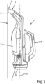
- Fig. 1 shows a schematic illustration of an embodiment of a suction device 1.
- the suction device 1 is a window vacuum cleaner for sucking in excess liquid 2 on plain surfaces 3, such as windows.
- the suction device 1 comprises an extraction lip 4.
- the suction device 1 comprises a device inlet 5 for sucking in the liquid 2 and air from outside of the suction device 1.
- the extraction lip 4 is designed to guide the liquid 2 to the device inlet 5.
- the extraction lip 4 may be part of the device inlet 5 comprises.
- the suction device 1 comprises a device outlet 6.
- the suction device 1 comprises a liquid container 7.
- the suction device 1 comprises a handle 8.
- the suction device comprises a device longitudinal axis A1 along a main extension of the suction device 1.
- fig. 1 shows the suction device 1 in an upright position.
- the suction device1 comprises a battery pack 9 for supplying the suction device 1.
- the suction device 1 is portable.
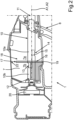
- Fig. 2 shows a schematic illustration of a cross section of another embodiment of the suction device 1.
- the suction device 1 comprises a pipe 10 with a pipe inlet 11 and a pipe outlet 12.
- the pipe inlet 11 and the pipe outlet 12 are arranged on opposite sides of the pipe 10.
- the pipe inlet 11 is connected to the device inlet 5.
- the pipe outlet 12 is connected to the device outlet 6.
- the pipe 10 comprises a container inlet opening 13, a container outlet opening 14 and a structure 15.
- the container inlet opening 13 is intended for leading the sucked in liquid 2 and air from the pipe 10 into the liquid container 7.
- the container outlet opening 14 is intended for leading the sucked in air from the liquid container 7 back into the pipe 10.
- the structure 15 is designed and arranged to block a direct flow of the sucked in liquid 2 and air from the pipe inlet 11 to the pipe outlet 12.
- the pipe 10 runs at least partially through the liquid container 7, such that the container inlet opening 13 and the container outlet opening 14 are arranged inside the liquid container 7.
- the suction device 1 comprises a retaining plate 16 with an outer circumferential edge 17.
- the outer circumferential edge 17 is at least partially adjacent to an inner wall 18 of the liquid container 7.
- the retaining plate 16 is arranged inside the liquid container 7 and axially arranged between the container inlet opening 13 and the container outlet opening 14.
- the retaining plate 16 is designed to retain at least a part of the sucked in liquid 2 from flowing from the liquid container 7 back into the pipe 10 via the container outlet opening 14.
- the outer circumferential edge 17 is adjacent to an inner wall 18 of the liquid container 7 in a first region 19 of the inner wall 18 facing the handle 8.
- the suction device comprises a fan device 20.
- the fan device 20 is arranged and configured to cause an air flow through the suction device 1 from the pipe inlet 11 through a first part 10a of the pipe 10 to the container inlet opening 13 through the liquid container 7 to the container outlet opening 14 through a second part 10 b of the pipe 10 to the pipe outlet 12.
- the battery pack 9 is for supplying the fan device 20 with energy.
- the retaining plate 16 divides the liquid container 7 into a container outlet region 7a and a container inlet region 7b.
- the first part 10a of the pipe 10 comprises the container inlet opening 13 and its main part is in the container outlet region 7a, but the container inlet opening 13 reaches into the container inlet region 7b.
- the second part 10b of the pipe 10 comprises the container outlet opening 14 and its main part is in the container inlet region 7b, but the container outlet opening 14 reaches into the container outlet region 7a.
- the pipe comprises a pipe longitudinal axis A2 parallel to the device axis A1.
- Fig. 2 shows the suction device 1 in a tilted position during an overhead operation.
- the device axis A1 is rotated by 90° in the tilted position shown in fig. 2 compared to the upright positon shown in fig. 1 .
- the liquid 2 flows in the liquid container 7 in a direction of the handle 8.
- the retaining plate 16 reduces the amount of the liquid 2, which gets from the container inlet region 7b to the container outlet region 7a.
- Fig. 3 shows a schematic view of the retaining plate 16 of another embodiment of the suction device 1.
- the retaining plate 16 comprises a cutout 21 at a second region 22 ( fig. 2 ) of the inner wall 18 of the liquid container 7 opposite to the first region 19, such that the edge 17 is not adjacent to the inner wall 18 at the second region 22 of the inner wall 18.
- the edge 17 is completely adjacent to the inner wall 18 except for the second region 22.
- the edge 17 is at least partially adjacent to the liquid container 7.
- the retaining plate 16 has a hole 25 for passing the pipe 10 through the retaining plate 16. In particular, the retaining plate 16 reaches around the pipe 10.
- the retaining plate 16 comprises two plate portions 23, 24.
- the two plate portions 23, 24 are joined along a connection line 26.
- the connection line 26 runs for example through the centre of the hole 25.
- the two plate portions 23, 24 enclose an angle ⁇ of less than 180° with each other seen from device inlet 5.
- the angle ⁇ is bigger than 90°, in particular between 150° and 170°.
- the connection line 26 forms an edge, which forms a drainage structure for guiding the liquid 2 towards the outer circumferential edge 17.
- the connection line 26 runs along a bending axis A3, which is perpendicular to the longitudinal pipe axis A2.
- Fig. 4 shows a schematic view of a cross section of the retaining plate 16 of another embodiment of the suction device 1.
- the retaining plate 16 comprises the two plate portions 23, 24 and a first further plate portion 23a.
- the first further plate portion 23a is adjacent to one of the two plate portions 23, 24.
- the first further plate portion 23a is adjacent to the plate portion 24.
- the first further plate portion 23a and the adjacent plate portion 24 enclose the angle ⁇ . It is also possible, that the enclosed angle of the first further plate portion 23a and the adjacent plate portion 24 is different to the angle ⁇ .
- Fig. 5 shows a schematic view of a cross section of the retaining plate 16 of another embodiment of the suction device 1.
- the retaining plate 16 comprises the two plate portions 23, 24, the first further plate portion 23a and a second further plate portion 23b.
- the second further plate portion 23b is adjacent to the first further plate portion 23a.
- the second further plate portion 23b is adjacent to the first further plate portion 23a.
- the second further plate portion 23b and the adjacent first further plate portion 23a enclose the angle ⁇ . It is also possible, that the enclosed angle of the second further plate portion 23b and the adjacent first further plate portion 23a is different to the angle ⁇ .
- Fig. 6 shows a schematic illustration of a cross section in perspective of another embodiment of the suction device 1.
- Fig. 6 is a perspective view of Fig. 2 .
- Fig. 7 shows a schematic top view of a cross section of another embodiment of the suction device 1.
- the retaining plate 16 is arranged oblique with respect to at least one axis, which is perpendicular to the device axis A1, in particular, to the pipe axis A2.
- the suction device 1 comprises a transverse axis A4, which is perpendicular to the device axis A1 and parallel to the extraction lip 4.
- the two plate portions 23, 24 are oblique with respect to the transverse axis A4.
- the retaining plate 16 is oblique with respect to an axis A5 ( Fig. 6 ), which is perpendicular to the transverse axis A4 and perpendicular to the pipe axis A2.
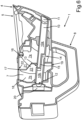
- Fig. 8 shows a schematic illustration of a cross section of another embodiment of the suction device 1.
- the suction device 1 comprises a manifold 27.
- the manifold 27 surrounds the pipe 10 circumferentially at an axial position of the container outlet opening 14 and covers the container outlet opening 14.
- the manifold 27 comprises a manifold opening 28.
- the manifold opening 28 is arranged opposite to the container outlet opening 14 in radial direction.
- the manifold opening 28 is closer to a geometrical centre 7c of the liquid container 7 than the outlet opening 28.
- the suction device 1 of Fig. 8 also comprises the retaining plate 16. However, in other implementations, the suction device 1 comprises the manifold 27 but not the retaining plate 16.
- Fig. 9 shows a schematic illustration of a cross section of the manifold 27 of another embodiment of the suction device 1.
- the manifold 27 comprises at least one baffle 29, 30 for deflecting the liquid 2 entering the manifold 27 from the liquid container 7.
- the manifold 27 comprises a hole 27a, which clasps the pipe 10.
- the at least one baffle 29, 30 has a U-shape. An opening 31, 32 of the U-shape is directed towards the liquid container 7.
- Fig. 10 shows a schematic view of a cross section of another embodiment of the suction device 1.
- Fig. 10 shows the manifold 27 and the pipe 10.
- the manifold 27 is designed to guide the liquid 2 and air from the liquid container 7 via the manifold opening 28 into the manifold 27.
- the manifold 27 is designed to guide the air via the container outlet opening into the pipe. For example, the liquid 2 is partially guided back into liquid container 7.
- Fig. 11 shows a schematic view of another embodiment of the suction device 1.
- Fig. 11 shows in a perspective view the manifold 27 and the pipe 10.
- the example shows a suction device 1, which overcomes the problem of water flowing out of the suction device 1 when used in overhead position.
Landscapes
- Details Of Rigid Or Semi-Rigid Containers (AREA)
Abstract
- the suction device (1) comprises a device inlet (5), a liquid container (7) and a pipe (10);
- the pipe (10) comprises a container inlet opening (13), a container outlet opening (14) and a structure (15) for blocking a direct flow of the sucked in liquid (2) and air from a pipe inlet (11) to a pipe outlet (12); and
- the suction device (1) comprises a retaining plate (16), which is arranged inside the liquid container (7) and axially between the container inlet opening (13) and the container outlet opening (14) and is designed to retain at least a part of the sucked in liquid (2) from flowing from the liquid container (7) into the pipe (10) via the container outlet opening (14).
Description
- The invention is concerned with a suction device for a liquid.
- Window vacuum cleaners are known. Window vacuum cleaners are suction devices, which are designed to suck in air and excess water from a window surface. Such window vacuum cleaners may separate the water from the air and store the water inside a liquid container. A problem of the known window vacuum cleaners is that sucked in water may not reliably remain in the liquid container of the window vacuum cleaner, but may sucked in again and blown out of the window vacuum cleaner with the air stream. Thus, water may reach electronic contacts or components of the window vacuum cleaner.
- It is an object of the present invention to provide a suction device, which reduces the amount of sucked in water, which is blown out of the suction device, in particular by flowing back from the liquid container into the air stream.
- The object is accomplished by the respective subject matter of the independent claims. Advantageous developments with convenient and non-trivial further embodiments of the invention are specified in the following description, the dependent claims and the figures.
- The invention also comprises embodiments that provide features, which afford additional technical advantages.
- A first aspect of the invention concerns a suction device for a liquid. The suction device comprises a device inlet for sucking in liquid and air from outside of the suction device. The suction device comprises a liquid container. The suction device comprises a pipe with a pipe inlet and a pipe outlet. The pipe inlet and the pipe outlet are arranged on opposite sides of the pipe. The pipe inlet is connected to the device inlet. The pipe comprises a container inlet opening, a container outlet opening and a structure. The container inlet opening is intended and arranged for leading the sucked in liquid and air from the pipe into the liquid container. The container outlet opening is intended and arranged for leading the sucked in air from the liquid container back into the pipe. The structure, also denoted as blocking structure, is intended for blocking a direct flow of the sucked in liquid and air from the pipe inlet to the pipe outlet.
- The pipe runs at least partially through the liquid container, such that the container inlet opening and the container outlet opening are arranged inside the liquid container. The suction device comprises a retaining plate with an outer circumferential edge. The outer circumferential edge is at least partially adjacent to an inner wall of the liquid container, in particular such that water cannot pass between the outer circumferential edge and the inner wall in a region where the outer circumferential edge is adjacent to the inner wall. The retaining plate is arranged inside the liquid container and axially arranged between the container inlet opening and the container outlet opening. The retaining plate is designed to retain at least a part of the sucked in liquid from flowing from the liquid container back into the pipe via the container outlet opening.
- Hence, the suction device reduces the amount of liquid, which flows from the liquid container back into the pipe via the container outlet opening. Therefore, the amount of liquid blown out of the suction device is reduced.
- The suction device is for example designed to clean a surface, such as a window, by sucking in excess liquid, also denoted as dirt water, at the device inlet. Liquid and air flow through a first part of the pipe via the container inlet opening into the container. Due to gravity, the liquid flows to a bottom side of the container. The retaining plate prevents most of the liquid from flowing too far away from the bottom side. The sucked in air leaves the liquid container via the container outlet opening into a second part of the pipe. From the second part of the pipe, the air leaves the suction device through the pipe outlet.
- The pipe inlet and the pipe outlet are arranged on opposite sides of the pipe on a longitudinal axis of the pipe. The longitudinal axis of the pipe runs along a main extension of the pipe. In particular, the container inlet opening and the container outlet opening are arranged radially on opposite sides of the pipe.
- In particular, the retaining plate divides the liquid container in two regions, for example, one first inlet region surrounding the container inlet opening and a second outlet region surrounding the container outlet opening. For example, the inlet region is closer to the pipe outlet than the outlet region and the outlet region is closer to the device inlet than the inlet region.
- In particular, the suction device is a portable suction device. Where applicable, the blocking structure is arranged inside the pipe. For example, the blocking structure sections the pipe into an inlet section connected to the device inlet and an outlet section connected to the pipe outlet. In particular, the inlet section comprises the container inlet opening and the outlet section comprises the container outlet opening.
- In an embodiment, the suction device comprises a handle. The outer circumferential edge of the retaining plate is adjacent to the inner wall of the liquid container in a first region of the inner wall facing the handle. The first region may be called handle region.
- This embodiment prevents the liquid from reaching the container outlet opening, for example during an overhead operation.
- During the overhead operation, the device opening is upward oriented, for example, to clean a horizontal surface.
- In particular, the handle is on a side of the suction device facing away from a surface to be cleaned, if the suction device is used as intended. In particular, no liquid and no air is guided inside or through the handle.
- In an embodiment, the retaining plate comprises a cutout at a second region of the inner wall of the liquid container opposite to the first region, such that the edge is not adjacent to the inner wall at the second region of the inner wall. The second region may be called cutout region.
- The edge is not adjacent to the inner wall at the second region such that air can stream from the container inlet opening through the cutout to the container outlet opening. If some of the liquid passes the cutout, it can flow back through the cutout.
- This embodiment improves the operation of the suction device.
- In an embodiment, the edge is completely adjacent to the inner wall except for the second region.
- This prevents most of the liquid from the container outlet opening. In other words, this prevents most of the liquid from flowing from the inlet region of the liquid container to the outlet region of the liquid container.
- In particular, the edge is at least partially adjacent to the liquid container in the second region. For example, the cutout has a C-, V- or U-shape or approximately such a shape, such that an adjacent part of the cutout region of the retaining plate is adjacent to the inner wall of the liquid container in the second region. This is especially advantageous for a side way operation of the suction device.
- It is possible, that the cutout is symmetric to the longitudinal axis of the pipe. However, it is also possible, that the cutout is asymmetric, such that one remaining side of the C-, V- or U-shaped cutout is broader than the other is. For example, right-handers usually will turn the suction device counter clockwise seen from the handle. In this case, it is advantageous in an embodiment, if the broader remaining side of the cutout is on the left side seen from the handle in an upright position of the suction device.
- In an embodiment, the retaining plate covers more than 70% of a cross sectional area of the liquid container.
- This improves an effect of the retaining plate to prohibit the liquid from entering the outlet region of the liquid container.
- In particular, the retaining plate covers more than 75%, in particular, more than 80%, in particular, more than 90%, of the cross sectional area of the liquid container. For example, the cross sectional area is perpendicular to the longitudinal axis of the pipe.
- In an embodiment, the retaining plate is arranged oblique with respect to at least one axis. The at least one axis is perpendicular to a longitudinal axis of the suction device.
- Hence, if some of the liquid reaches the outlet region of the liquid container, the oblique retaining plate guides this liquid back into the inlet region of the liquid container.
- In particular, the longitudinal axis of the suction device is parallel to the longitudinal axis of the pipe. Preferably, the retaining plate is oblique regarding to one or two tilting axes, both perpendicular to the longitudinal axis of the device.
- In an embodiment, the retaining plate is not flat but bent.
- Therefore, if some of the liquid reaches the outlet region of the liquid container, the bent retaining plate guides this liquid over a predetermined way back into the inlet region of the liquid container.
- In particular, the retaining plate comprises at least one bending axis. Optionally, the at least one bending axis is a symmetry axis of the retaining plate. However, other configurations of the at least one bending axis are possible. For example, the bending is asymmetric or not along a straight line.
- In an embodiment, the retaining plate comprises a drainage structure on a surface of the retaining plate for guiding liquid towards the outer circumferential edge.
- This further improves the guiding of some of the liquid from the outlet region back into the inlet region.
- In particular, the drainage structure may be denoted as a drainage channel or a drainage edge. For example, the bending axis is configured as the drainage structure. Alternatively or additionally, the drainage structure comprises one or more grooves.
- In an embodiment, the retaining plate has a hole for passing the pipe through the plate. The retaining plate surrounds the pipe.
- This allows that the inlet region of the liquid container is closer to the pipe outlet than the outlet region of the liquid container.
- In particular, the retaining plate reaches around the pipe completely at a section of the pipe.
- In an embodiment, the retaining plate comprises at least two plate portions. Two plate portions of the at least two plate portions are joined along a connection line. The connection line runs through the hole. The two plate portions of the at least two plate portions enclose an angle of less than 180° with each other seen from the device inlet.
- In particular, the connection line is configured as part of the drainage structure. For example, the connection line forms an edge, which forms the drainage structure. Preferably, the connection line runs through the center of the hole. Preferably, each of the plate portions is flat.
- Optionally, the angle is larger than 90°. In particular, the angle is between 150° to 170°. It is possible that one of the two plate portions and another adjacent plate portion of the at least two plate portions enclose the same angle with each other.
- In an embodiment, the suction device comprises a manifold, which surrounds the pipe circumferentially at a position of the container outlet opening. The manifold covers the container outlet opening and comprises a manifold opening. The manifold opening is arranged opposite to the container outlet opening in radial direction.
- The manifold protects the container outlet opening from most of the liquid. In particular, the manifold redirects the air stream.
- In an embodiment, the manifold comprises at least one baffle for deflecting liquid entering the manifold from the liquid container.
- The at least one baffle blocks most of the liquid, such that it does not enter the manifold. In particular, the manifold comprises at least one drain. For example, the at least one drain leads the liquid deflected at the at least one baffle back into the liquid container.
- In an embodiment, the manifold is designed to guide liquid and air from the liquid container via the manifold opening into the manifold. The manifold is designed to guide the air via the container outlet opening into the pipe.
- This further reduces the amount of water entering the outlet section of the pipe. In particular, the liquid is partially guided back into liquid container.
- In an embodiment, the manifold opening is arranged farther away from the inner wall of the liquid container than the container outlet opening.
- In particular, the manifold opening is radially on an opposite side of pipe. For example, the container inlet opening and the manifold opening are radially on the same side of the pipe. In particular, the manifold opening is closer to a geometrical center of the liquid container than the container outlet opening.
- This design reduces a probability that the liquid reaches the manifold opening.
- In an embodiment, the at least one baffle has a U-shape.
- In particular, an opening of the U-shape is directed towards the liquid container. This improves the retention of the liquid.
- In an embodiment, the suction device comprises a suction generator. In particular, the suction generator is designed as a fan device. The suction generator is arranged and configured to cause an airflow through the suction device from the pipe inlet through a first part of the pipe to the container inlet opening through the liquid container to the container outlet opening through a second part of the pipe to the pipe outlet.
- In an embodiment, the suction device comprises a battery pack for supplying the suction generator.
- In an embodiment, the suction device is a window cleaning device.
- In an embodiment, the suction device comprises a housing with an interface for connecting a battery pack to the housing mechanically and electrically.
- The battery pack can be connected mechanically and electrically to a housing of the suction device. For example, the battery pack can be connected to the housing of the electrical appliance, in particular in a non-destructively detachable manner, for example via a snap-in connection, a plug-in connection and/or a clamp connection. In particular, the mechanical connection of the battery pack to the housing of the suction device can be released without having to release a material connection. Preferably, the mechanical connection can be released manually as intended without the use of other tools. In other words, the battery pack is configured as an interchangeable battery pack, in particular a system battery pack. For electrical and mechanical connection, the housings of the battery pack and the suction device may have respective interfaces.
- A second aspect of the invention concerns a suction device for a liquid. The suction device comprises a device inlet for sucking in liquid and air from outside of the suction device. The suction device comprises a liquid container. The suction device comprises a pipe with a pipe inlet and a pipe outlet. The pipe inlet and the pipe outlet are arranged on opposite sides of the pipe. The pipe inlet is connected to the device inlet. The pipe comprises a container inlet, a container outlet and a structure. The pipe inlet is intended for leading the sucked in liquid and air from the pipe into the liquid container. The container outlet is intended for leading the sucked in air from the liquid container back into the pipe. The structure is intended for blocking a direct flow of the sucked in liquid and air from the pipe inlet to the pipe outlet. The pipe runs at least partially through the liquid container, such that the container inlet and the container outlet are arranged inside the liquid container. The suction device comprises a manifold. The manifold surrounds the pipe circumferentially at a position of the container outlet opening and covers the container outlet opening and comprises a manifold opening. The manifold opening is arranged opposite to the container outlet opening.
- Further implementations of the suction device according to the second aspect of the invention follow directly from the various embodiments of the suction device according to the first aspect of the invention and vice versa. In particular, individual features and corresponding explanations as well as advantages relating to the various implementations of the suction device according to the first aspect of the invention can be transferred analogously to corresponding implementations of the suction device according to the second aspect of the invention.
- The invention also comprises the combinations of the features of the different embodiments.
- In the following, exemplary implementations of the invention are described with reference to the figures. In the figures, identical or functionally identical elements may be denoted by the same reference signs. The description of identical or functionally identical elements is not necessarily repeated with respect to different figures. The figures show in:
- Fig. 1
- a schematic illustration of an exemplary embodiment of the inventive suction device;
- Fig. 2
- a schematic illustration of a cross section of another exemplary embodiment of the inventive suction device;
- Fig. 3
- a schematic view a retaining plate of another exemplary embodiment of the inventive suction device;
- Fig. 4
- a schematic view of a cross section of a retaining plate of another exemplary embodiment of the inventive suction device;
- Fig. 5
- a schematic view of a cross section of a retaining plate of another exemplary embodiment of the inventive suction device;
- Fig. 6
- a schematic illustration of a cross section in perspective of another exemplary embodiment of the inventive suction device;
- Fig. 7
- a schematic top view of a cross section of another exemplary embodiment of the inventive suction device;
- Fig. 8
- a schematic illustration of a cross section of another exemplary embodiment of the inventive suction device;
- Fig. 9
- a schematic illustration of a cross section of a manifold of another exemplary embodiment of the inventive suction device;
- Fig. 10
- a schematic view of a cross section of another exemplary embodiment of the inventive suction device; and
- Fig. 11
- a schematic view of another exemplary embodiment of the inventive suction device.
- The embodiments explained in the following are preferred embodiments of the invention. However, in the embodiments, the described components of the respective embodiment each represent individual features of the invention which are to be considered independently of each other and which each develop the invention also independently of each other and thereby are also to be regarded as a component of the invention in individual manner or in another than the shown combination. Furthermore, the described embodiments can also be supplemented by further features of the invention already described.
-
Fig. 1 shows a schematic illustration of an embodiment of asuction device 1. For example, thesuction device 1 is a window vacuum cleaner for sucking inexcess liquid 2 onplain surfaces 3, such as windows. In particular, thesuction device 1 comprises anextraction lip 4. Thesuction device 1 comprises adevice inlet 5 for sucking in theliquid 2 and air from outside of thesuction device 1. For example, theextraction lip 4 is designed to guide theliquid 2 to thedevice inlet 5. In particular, theextraction lip 4 may be part of thedevice inlet 5 comprises. In particular, thesuction device 1 comprises adevice outlet 6. Thesuction device 1 comprises aliquid container 7. For example, thesuction device 1 comprises ahandle 8. - The suction device comprises a device longitudinal axis A1 along a main extension of the
suction device 1. In particular,fig. 1 shows thesuction device 1 in an upright position. - In an embodiment, the suction device1 comprises a battery pack 9 for supplying the
suction device 1. In particular, thesuction device 1 is portable. -
Fig. 2 shows a schematic illustration of a cross section of another embodiment of thesuction device 1. Thesuction device 1 comprises apipe 10 with apipe inlet 11 and apipe outlet 12. Thepipe inlet 11 and thepipe outlet 12 are arranged on opposite sides of thepipe 10. Thepipe inlet 11 is connected to thedevice inlet 5. In particular, thepipe outlet 12 is connected to thedevice outlet 6. Thepipe 10 comprises a container inlet opening 13, acontainer outlet opening 14 and astructure 15. The container inlet opening 13 is intended for leading the sucked inliquid 2 and air from thepipe 10 into theliquid container 7. The container outlet opening 14 is intended for leading the sucked in air from theliquid container 7 back into thepipe 10. Thestructure 15 is designed and arranged to block a direct flow of the sucked inliquid 2 and air from thepipe inlet 11 to thepipe outlet 12. - The
pipe 10 runs at least partially through theliquid container 7, such that the container inlet opening 13 and the container outlet opening 14 are arranged inside theliquid container 7. Thesuction device 1 comprises a retainingplate 16 with an outercircumferential edge 17. The outercircumferential edge 17 is at least partially adjacent to aninner wall 18 of theliquid container 7. The retainingplate 16 is arranged inside theliquid container 7 and axially arranged between the container inlet opening 13 and thecontainer outlet opening 14. The retainingplate 16 is designed to retain at least a part of the sucked inliquid 2 from flowing from theliquid container 7 back into thepipe 10 via thecontainer outlet opening 14. - In an embodiment, the outer
circumferential edge 17 is adjacent to aninner wall 18 of theliquid container 7 in afirst region 19 of theinner wall 18 facing thehandle 8. - In an embodiment, the suction device comprises a
fan device 20. Preferably, thefan device 20 is arranged and configured to cause an air flow through thesuction device 1 from thepipe inlet 11 through afirst part 10a of thepipe 10 to the container inlet opening 13 through theliquid container 7 to the container outlet opening 14 through asecond part 10 b of thepipe 10 to thepipe outlet 12. - In particular, the battery pack 9 is for supplying the
fan device 20 with energy. - For example, the retaining
plate 16 divides theliquid container 7 into acontainer outlet region 7a and acontainer inlet region 7b. In particular, thefirst part 10a of thepipe 10 comprises the container inlet opening 13 and its main part is in thecontainer outlet region 7a, but the container inlet opening 13 reaches into thecontainer inlet region 7b. In particular, thesecond part 10b of thepipe 10 comprises thecontainer outlet opening 14 and its main part is in thecontainer inlet region 7b, but the container outlet opening 14 reaches into thecontainer outlet region 7a. - The pipe comprises a pipe longitudinal axis A2 parallel to the device axis A1. In particular,
Fig. 2 shows thesuction device 1 in a tilted position during an overhead operation. For example, the device axis A1 is rotated by 90° in the tilted position shown infig. 2 compared to the upright positon shown infig. 1 . In the tilted position, theliquid 2 flows in theliquid container 7 in a direction of thehandle 8. The retainingplate 16 reduces the amount of theliquid 2, which gets from thecontainer inlet region 7b to thecontainer outlet region 7a. -
Fig. 3 shows a schematic view of the retainingplate 16 of another embodiment of thesuction device 1. - In an embodiment, the retaining
plate 16 comprises acutout 21 at a second region 22 (fig. 2 ) of theinner wall 18 of theliquid container 7 opposite to thefirst region 19, such that theedge 17 is not adjacent to theinner wall 18 at thesecond region 22 of theinner wall 18. For example, theedge 17 is completely adjacent to theinner wall 18 except for thesecond region 22. In particular, theedge 17 is at least partially adjacent to theliquid container 7. - In an embodiment, the retaining
plate 16 has ahole 25 for passing thepipe 10 through the retainingplate 16. In particular, the retainingplate 16 reaches around thepipe 10. - In an embodiment, the retaining
plate 16 comprises twoplate portions plate portions connection line 26. Theconnection line 26 runs for example through the centre of thehole 25. The twoplate portions device inlet 5. For example, the angle ϕ is bigger than 90°, in particular between 150° and 170°. In particular, theconnection line 26 forms an edge, which forms a drainage structure for guiding theliquid 2 towards the outercircumferential edge 17. For example, theconnection line 26 runs along a bending axis A3, which is perpendicular to the longitudinal pipe axis A2. -
Fig. 4 shows a schematic view of a cross section of the retainingplate 16 of another embodiment of thesuction device 1. In this embodiment, the retainingplate 16 comprises the twoplate portions further plate portion 23a. For example, the firstfurther plate portion 23a is adjacent to one of the twoplate portions further plate portion 23a is adjacent to theplate portion 24. Preferably, the firstfurther plate portion 23a and theadjacent plate portion 24 enclose the angle ϕ. It is also possible, that the enclosed angle of the firstfurther plate portion 23a and theadjacent plate portion 24 is different to the angle ϕ. -
Fig. 5 shows a schematic view of a cross section of the retainingplate 16 of another embodiment of thesuction device 1. In this embodiment, the retainingplate 16 comprises the twoplate portions further plate portion 23a and a secondfurther plate portion 23b. For example, the secondfurther plate portion 23b is adjacent to the firstfurther plate portion 23a. In particular, the secondfurther plate portion 23b is adjacent to the firstfurther plate portion 23a. Preferably, the secondfurther plate portion 23b and the adjacent firstfurther plate portion 23a enclose the angle ϕ. It is also possible, that the enclosed angle of the secondfurther plate portion 23b and the adjacent firstfurther plate portion 23a is different to the angle ϕ. -
Fig. 6 shows a schematic illustration of a cross section in perspective of another embodiment of thesuction device 1. For example,Fig. 6 is a perspective view ofFig. 2 . -
Fig. 7 shows a schematic top view of a cross section of another embodiment of thesuction device 1. Preferably, the retainingplate 16 is arranged oblique with respect to at least one axis, which is perpendicular to the device axis A1, in particular, to the pipe axis A2. For example, thesuction device 1 comprises a transverse axis A4, which is perpendicular to the device axis A1 and parallel to theextraction lip 4. In particular, the twoplate portions plate 16 is oblique with respect to an axis A5 (Fig. 6 ), which is perpendicular to the transverse axis A4 and perpendicular to the pipe axis A2. -
Fig. 8 shows a schematic illustration of a cross section of another embodiment of thesuction device 1. - In an embodiment, the
suction device 1 comprises a manifold 27. For example, the manifold 27 surrounds thepipe 10 circumferentially at an axial position of thecontainer outlet opening 14 and covers thecontainer outlet opening 14. Preferably, the manifold 27 comprises amanifold opening 28. In particular, themanifold opening 28 is arranged opposite to the container outlet opening 14 in radial direction. For example, themanifold opening 28 is closer to ageometrical centre 7c of theliquid container 7 than theoutlet opening 28. - The
suction device 1 ofFig. 8 also comprises the retainingplate 16. However, in other implementations, thesuction device 1 comprises the manifold 27 but not the retainingplate 16. -
Fig. 9 shows a schematic illustration of a cross section of themanifold 27 of another embodiment of thesuction device 1. - In an embodiment, the manifold 27 comprises at least one
baffle liquid 2 entering the manifold 27 from theliquid container 7. For example, the manifold 27 comprises ahole 27a, which clasps thepipe 10. In particular, the at least onebaffle opening liquid container 7. -
Fig. 10 shows a schematic view of a cross section of another embodiment of thesuction device 1.Fig. 10 shows the manifold 27 and thepipe 10. - In an embodiment, the manifold 27 is designed to guide the
liquid 2 and air from theliquid container 7 via themanifold opening 28 into themanifold 27. In particular, the manifold 27 is designed to guide the air via the container outlet opening into the pipe. For example, theliquid 2 is partially guided back intoliquid container 7. -
Fig. 11 shows a schematic view of another embodiment of thesuction device 1.Fig. 11 shows in a perspective view themanifold 27 and thepipe 10. - Overall, the example shows a
suction device 1, which overcomes the problem of water flowing out of thesuction device 1 when used in overhead position.
Claims (19)
- Suction device (1) for a liquid (2), wherein:- the suction device (1) comprises a device inlet (5) for sucking in liquid (2) and air from outside of the suction device (1);- the suction device (1) comprises a liquid container (7);- the suction device (1) comprises a pipe (10) with a pipe inlet (11) and a pipe outlet (12) arranged on opposite sides of the pipe (10), the pipe inlet (11) being connected to the device inlet (5);- the pipe (10) comprises a container inlet opening (13) for leading the sucked in liquid (2) and air from the pipe (10) into the liquid container (7), a container outlet opening (14) for leading the sucked in air from the liquid container (7) back into the pipe (10), and a structure (15) for blocking a direct flow of the sucked in liquid (2) and air from the pipe inlet (11) to the pipe outlet (12);- the pipe (10) runs at least partially through the liquid container (7), such that the container inlet opening (13) and the container outlet opening (14) are arranged inside the liquid container (7); and- the suction device (1) comprises a retaining plate (16) with an outer circumferential edge (17), which is at least partially adjacent to an inner wall (18) of the liquid container (7), wherein the retaining plate (16) is arranged inside the liquid container (7) and axially arranged between the container inlet opening (13) and the container outlet opening (14) and is designed to retain at least a part of the sucked in liquid (2) from flowing from the liquid container (7) into the pipe (10) via the container outlet opening (14).
- Suction device (1) according to any of the preceding claims, wherein the suction device (1) comprises a handle (8), wherein the outer circumferential edge (17) is adjacent to the inner wall (18) of the liquid container (7) in a first region (19) of the inner wall (18) facing the handle (8).
- Suction device (1) according to any of the preceding claims, wherein the retaining plate (16) comprises a cutout (21) at a second region (22) of the inner wall (18) of the liquid (2) container (7) opposite to the first region (19), such that the edge (17) is not adjacent to the inner wall (18) at the second region (22) of the inner wall (18).
- Suction device (1) according to claim 3, wherein the edge (17) is completely adjacent to the inner wall (18) except for the second region (22).
- Suction device (1) according to any of the preceding claims, wherein the retaining plate (16) covers more than 70% of a cross sectional area of the liquid container (7).
- Suction device (1) according to any of the preceding claims, wherein the retaining plate (16) is arranged oblique with respect to at least one axis (A4, A5), which is perpendicular to a longitudinal axis (A1, A2) of the suction device (1).
- Suction device (1) according to any of the preceding claims, wherein the retaining plate (16) is bent.
- Suction device (20) according to any of the preceding claims, wherein the retaining plate (16) comprises a drainage structure on a surface of the retaining plate (16) for guiding liquid (2) on the surface of the retaining plate (16) towards the outer circumferential edge (17).
- Suction device (1) according to any of the preceding claims, wherein the retaining plate (16) has a hole (25) for the pipe (10) and surrounds the pipe (10).
- Suction device (1) according to claim 9, wherein the retaining plate (16) comprises at least two plate portions, wherein two plate portions (23, 24) of the at least two plate portions are joined along a connection line (26), wherein the connection line (26) runs through the hole (25), wherein the two plate portions (23, 24) of the at least two plate portions enclose an angle (ϕ) of less than 180° with each other.
- Suction device (1) according to any of the preceding claims, wherein the suction device (1) comprises a manifold (27), which surrounds the pipe (10) at a position of the container outlet opening (14) and covers the container outlet opening (14) and comprises a manifold opening (28), wherein the manifold opening (28) is arranged opposite to the container outlet opening (14).
- Suction device (1) according to claim 11, wherein the manifold (27) comprises at least one baffle (29, 30) for deflecting liquid (2) entering the manifold (27) from the liquid container (7).
- Suction device (1) according to any of the claims 11 to 12, wherein the manifold (27) is designed to guide liquid (2) and air from the liquid container (7) via the manifold opening (28) into the manifold (27), wherein the manifold (27) is designed to guide the air via the container outlet opening (14) into the pipe (10).
- Suction device (1) according to any of the claims 11 to 13, wherein the manifold opening (28) is arranged farther away from the inner wall (18) of the liquid container (7) than the container outlet opening (14).
- Suction device (1) according to any of the claims 11 to 14, wherein the at least one baffle (29) has a U-shape.
- Suction device (1) for a liquid (2), wherein:- the suction device (1) comprises a device inlet (5) for sucking in liquid (2) and air from outside of the suction device (1);- the suction device (1) comprises a liquid container (7);- the suction device (1) comprises a pipe (10) with a pipe inlet (11) and a pipe outlet (12) arranged on opposite sides of the pipe (10), the pipe inlet (11) being connected to the device inlet (5);- the pipe (10) comprises a container inlet opening (13) for leading the sucked in liquid (2) and air from the pipe (10) into the liquid container (7), a container outlet opening (14) for leading the sucked in air from the liquid container (7) back into the pipe (10), and a structure (15) for blocking a direct flow of the sucked in liquid (2) and air from the pipe inlet (11) to the pipe outlet (12),- the pipe (10) runs at least partially through the liquid container (7), such that the container inlet opening (13) and the container outlet opening (14) are arranged inside the liquid container (7);- the suction device (1) comprises a manifold (27), which surrounds the pipe (10) at a position of the container outlet opening (14) and covers the container outlet opening (14) and comprises a manifold opening (28), wherein the manifold opening (28) is arranged opposite to the container outlet opening (14).
- Suction device (1) according to any of the preceding claims, wherein the suction device (1) comprises a suction generator, which is arranged and configured to cause an air flow through the suction device (1) from the pipe inlet (11) through a first part (10a) of the pipe (10) to the container inlet opening (13) through the liquid container (7) to the container outlet opening (14) through a second part (10b) of the pipe (10) to the pipe outlet (12).
- Suction device (1) according to any of the preceding claims, wherein the suction device (1) is a window cleaning device.
- Suction device (1) according to any of the preceding claims, wherein the suction device (1) comprises a housing with an interface for connecting a battery pack (9) to the housing mechanically and electrically.
Priority Applications (1)
| Application Number | Priority Date | Filing Date | Title |
|---|---|---|---|
| EP23198302.4A EP4527270B1 (en) | 2023-09-19 | 2023-09-19 | SUCTION DEVICE FOR A LIQUID |
Applications Claiming Priority (1)
| Application Number | Priority Date | Filing Date | Title |
|---|---|---|---|
| EP23198302.4A EP4527270B1 (en) | 2023-09-19 | 2023-09-19 | SUCTION DEVICE FOR A LIQUID |
Publications (3)
| Publication Number | Publication Date |
|---|---|
| EP4527270A1 true EP4527270A1 (en) | 2025-03-26 |
| EP4527270C0 EP4527270C0 (en) | 2025-12-31 |
| EP4527270B1 EP4527270B1 (en) | 2025-12-31 |
Family
ID=88097702
Family Applications (1)
| Application Number | Title | Priority Date | Filing Date |
|---|---|---|---|
| EP23198302.4A Active EP4527270B1 (en) | 2023-09-19 | 2023-09-19 | SUCTION DEVICE FOR A LIQUID |
Country Status (1)
| Country | Link |
|---|---|
| EP (1) | EP4527270B1 (en) |
Citations (4)
| Publication number | Priority date | Publication date | Assignee | Title |
|---|---|---|---|---|
| DE102008004965B3 (en) * | 2008-01-11 | 2009-05-14 | Alfred Kärcher Gmbh & Co. Kg | Portable hard surface suction device |
| DE202014004864U1 (en) * | 2013-11-27 | 2014-07-07 | Ningbo Lucky Snow Mechanical Equipment Manufacturing And Trading Co., Ltd. | An air-liquid separator and a cleaner with the air-liquid separator for hard surfaces |
| WO2014121529A1 (en) * | 2013-02-05 | 2014-08-14 | Zhu Houlin | Improved water absorber of hard surfaces |
| DE102017121209A1 (en) * | 2017-09-13 | 2019-03-14 | Alfred Kärcher SE & Co. KG | Surface cleaning device |
-
2023
- 2023-09-19 EP EP23198302.4A patent/EP4527270B1/en active Active
Patent Citations (4)
| Publication number | Priority date | Publication date | Assignee | Title |
|---|---|---|---|---|
| DE102008004965B3 (en) * | 2008-01-11 | 2009-05-14 | Alfred Kärcher Gmbh & Co. Kg | Portable hard surface suction device |
| WO2014121529A1 (en) * | 2013-02-05 | 2014-08-14 | Zhu Houlin | Improved water absorber of hard surfaces |
| DE202014004864U1 (en) * | 2013-11-27 | 2014-07-07 | Ningbo Lucky Snow Mechanical Equipment Manufacturing And Trading Co., Ltd. | An air-liquid separator and a cleaner with the air-liquid separator for hard surfaces |
| DE102017121209A1 (en) * | 2017-09-13 | 2019-03-14 | Alfred Kärcher SE & Co. KG | Surface cleaning device |
Also Published As
| Publication number | Publication date |
|---|---|
| EP4527270C0 (en) | 2025-12-31 |
| EP4527270B1 (en) | 2025-12-31 |
Similar Documents
| Publication | Publication Date | Title |
|---|---|---|
| CN101262806B (en) | Dust collection devices for vacuum cleaners | |
| KR100613102B1 (en) | Suction structure assembly and vacuum cleaner with same | |
| EP3641612B1 (en) | A surface cleaning apparatus | |
| CN103491840A (en) | Cyclone separators for suction cleaning equipment | |
| WO2020024536A1 (en) | Vacuum cleaner | |
| KR20210012246A (en) | A vacuum cleaner | |
| US11998869B2 (en) | Filter element | |
| EP4527270B1 (en) | SUCTION DEVICE FOR A LIQUID | |
| KR20240166439A (en) | Air conditioner | |
| US20060093501A1 (en) | Suction port assembly of vacuum cleaner | |
| CN114190847B (en) | Sewage tank and floor cleaning machine | |
| EP2954814A1 (en) | Suction tool for electric cleaner and electric cleaner using same | |
| AU2004202983A1 (en) | Vacuum Cleaner | |
| KR20110067764A (en) | Flow noise reduction structure of vacuum cleaner | |
| EP2979601A1 (en) | Cleaner | |
| KR20160045622A (en) | Dust collection device | |
| KR101532910B1 (en) | Dual vortex vacuum cleaner | |
| CN103974651B (en) | Electric vacuum cleaner | |
| AU2018404657B2 (en) | Cleaner | |
| KR100756321B1 (en) | Case assembly for fan motor | |
| KR102081942B1 (en) | Cleaning Appliance | |
| KR101147778B1 (en) | A vacuum cleaner | |
| JP6416636B2 (en) | Dust collector and vacuum cleaner | |
| CN215457668U (en) | Dust collecting device and dust collector | |
| CN112190179B (en) | Electric vacuum cleaner |
Legal Events
| Date | Code | Title | Description |
|---|---|---|---|
| PUAI | Public reference made under article 153(3) epc to a published international application that has entered the european phase |
Free format text: ORIGINAL CODE: 0009012 |
|
| STAA | Information on the status of an ep patent application or granted ep patent |
Free format text: STATUS: THE APPLICATION HAS BEEN PUBLISHED |
|
| AK | Designated contracting states |
Kind code of ref document: A1 Designated state(s): AL AT BE BG CH CY CZ DE DK EE ES FI FR GB GR HR HU IE IS IT LI LT LU LV MC ME MK MT NL NO PL PT RO RS SE SI SK SM TR |
|
| STAA | Information on the status of an ep patent application or granted ep patent |
Free format text: STATUS: REQUEST FOR EXAMINATION WAS MADE |
|
| 17P | Request for examination filed |
Effective date: 20250703 |
|
| GRAP | Despatch of communication of intention to grant a patent |
Free format text: ORIGINAL CODE: EPIDOSNIGR1 |
|
| STAA | Information on the status of an ep patent application or granted ep patent |
Free format text: STATUS: GRANT OF PATENT IS INTENDED |
|
| INTG | Intention to grant announced |
Effective date: 20250923 |
|
| GRAS | Grant fee paid |
Free format text: ORIGINAL CODE: EPIDOSNIGR3 |
|
| GRAA | (expected) grant |
Free format text: ORIGINAL CODE: 0009210 |
|
| STAA | Information on the status of an ep patent application or granted ep patent |
Free format text: STATUS: THE PATENT HAS BEEN GRANTED |
|
| AK | Designated contracting states |
Kind code of ref document: B1 Designated state(s): AL AT BE BG CH CY CZ DE DK EE ES FI FR GB GR HR HU IE IS IT LI LT LU LV MC ME MK MT NL NO PL PT RO RS SE SI SK SM TR |
|
| REG | Reference to a national code |
Ref country code: CH Ref legal event code: F10 Free format text: ST27 STATUS EVENT CODE: U-0-0-F10-F00 (AS PROVIDED BY THE NATIONAL OFFICE) Effective date: 20251231 Ref country code: GB Ref legal event code: FG4D |
|
| REG | Reference to a national code |
Ref country code: DE Ref legal event code: R096 Ref document number: 602023010342 Country of ref document: DE |
|
| REG | Reference to a national code |
Ref country code: IE Ref legal event code: FG4D |
|
| U01 | Request for unitary effect filed |
Effective date: 20260126 |
|
| U07 | Unitary effect registered |
Designated state(s): AT BE BG DE DK EE FI FR IT LT LU LV MT NL PT RO SE SI Effective date: 20260202 |
|
| PG25 | Lapsed in a contracting state [announced via postgrant information from national office to epo] |
Ref country code: NO Free format text: LAPSE BECAUSE OF FAILURE TO SUBMIT A TRANSLATION OF THE DESCRIPTION OR TO PAY THE FEE WITHIN THE PRESCRIBED TIME-LIMIT Effective date: 20260331 |
|
| PG25 | Lapsed in a contracting state [announced via postgrant information from national office to epo] |
Ref country code: HR Free format text: LAPSE BECAUSE OF FAILURE TO SUBMIT A TRANSLATION OF THE DESCRIPTION OR TO PAY THE FEE WITHIN THE PRESCRIBED TIME-LIMIT Effective date: 20251231 |
|
| PG25 | Lapsed in a contracting state [announced via postgrant information from national office to epo] |
Ref country code: RS Free format text: LAPSE BECAUSE OF FAILURE TO SUBMIT A TRANSLATION OF THE DESCRIPTION OR TO PAY THE FEE WITHIN THE PRESCRIBED TIME-LIMIT Effective date: 20260331 |