EP4525579A1 - Electronic control unit - Google Patents
Electronic control unit Download PDFInfo
- Publication number
- EP4525579A1 EP4525579A1 EP24155711.5A EP24155711A EP4525579A1 EP 4525579 A1 EP4525579 A1 EP 4525579A1 EP 24155711 A EP24155711 A EP 24155711A EP 4525579 A1 EP4525579 A1 EP 4525579A1
- Authority
- EP
- European Patent Office
- Prior art keywords
- coolant
- control unit
- control board
- coolant jacket
- jacket
- Prior art date
- Legal status (The legal status is an assumption and is not a legal conclusion. Google has not performed a legal analysis and makes no representation as to the accuracy of the status listed.)
- Pending
Links
Images





Classifications
-
- H—ELECTRICITY
- H05—ELECTRIC TECHNIQUES NOT OTHERWISE PROVIDED FOR
- H05K—PRINTED CIRCUITS; CASINGS OR CONSTRUCTIONAL DETAILS OF ELECTRIC APPARATUS; MANUFACTURE OF ASSEMBLAGES OF ELECTRICAL COMPONENTS
- H05K7/00—Constructional details common to different types of electric apparatus
- H05K7/20—Modifications to facilitate cooling, ventilating, or heating
- H05K7/20845—Modifications to facilitate cooling, ventilating, or heating for automotive electronic casings
- H05K7/20872—Liquid coolant without phase change
-
- H—ELECTRICITY
- H05—ELECTRIC TECHNIQUES NOT OTHERWISE PROVIDED FOR
- H05K—PRINTED CIRCUITS; CASINGS OR CONSTRUCTIONAL DETAILS OF ELECTRIC APPARATUS; MANUFACTURE OF ASSEMBLAGES OF ELECTRICAL COMPONENTS
- H05K7/00—Constructional details common to different types of electric apparatus
- H05K7/20—Modifications to facilitate cooling, ventilating, or heating
- H05K7/20218—Modifications to facilitate cooling, ventilating, or heating using a liquid coolant without phase change in electronic enclosures
-
- B—PERFORMING OPERATIONS; TRANSPORTING
- B60—VEHICLES IN GENERAL
- B60R—VEHICLES, VEHICLE FITTINGS, OR VEHICLE PARTS, NOT OTHERWISE PROVIDED FOR
- B60R16/00—Electric or fluid circuits specially adapted for vehicles and not otherwise provided for; Arrangement of elements of electric or fluid circuits specially adapted for vehicles and not otherwise provided for
- B60R16/02—Electric or fluid circuits specially adapted for vehicles and not otherwise provided for; Arrangement of elements of electric or fluid circuits specially adapted for vehicles and not otherwise provided for electric constitutive elements
-
- H—ELECTRICITY
- H05—ELECTRIC TECHNIQUES NOT OTHERWISE PROVIDED FOR
- H05K—PRINTED CIRCUITS; CASINGS OR CONSTRUCTIONAL DETAILS OF ELECTRIC APPARATUS; MANUFACTURE OF ASSEMBLAGES OF ELECTRICAL COMPONENTS
- H05K5/00—Casings, cabinets or drawers for electric apparatus
- H05K5/0026—Casings, cabinets or drawers for electric apparatus provided with connectors and printed circuit boards [PCB], e.g. automotive electronic control units
-
- H—ELECTRICITY
- H05—ELECTRIC TECHNIQUES NOT OTHERWISE PROVIDED FOR
- H05K—PRINTED CIRCUITS; CASINGS OR CONSTRUCTIONAL DETAILS OF ELECTRIC APPARATUS; MANUFACTURE OF ASSEMBLAGES OF ELECTRICAL COMPONENTS
- H05K7/00—Constructional details common to different types of electric apparatus
- H05K7/20—Modifications to facilitate cooling, ventilating, or heating
- H05K7/20218—Modifications to facilitate cooling, ventilating, or heating using a liquid coolant without phase change in electronic enclosures
- H05K7/20254—Cold plates transferring heat from heat source to coolant
-
- H—ELECTRICITY
- H05—ELECTRIC TECHNIQUES NOT OTHERWISE PROVIDED FOR
- H05K—PRINTED CIRCUITS; CASINGS OR CONSTRUCTIONAL DETAILS OF ELECTRIC APPARATUS; MANUFACTURE OF ASSEMBLAGES OF ELECTRICAL COMPONENTS
- H05K7/00—Constructional details common to different types of electric apparatus
- H05K7/20—Modifications to facilitate cooling, ventilating, or heating
- H05K7/20218—Modifications to facilitate cooling, ventilating, or heating using a liquid coolant without phase change in electronic enclosures
- H05K7/20272—Accessories for moving fluid, for expanding fluid, for connecting fluid conduits, for distributing fluid, for removing gas or for preventing leakage, e.g. pumps, tanks or manifolds
-
- H—ELECTRICITY
- H05—ELECTRIC TECHNIQUES NOT OTHERWISE PROVIDED FOR
- H05K—PRINTED CIRCUITS; CASINGS OR CONSTRUCTIONAL DETAILS OF ELECTRIC APPARATUS; MANUFACTURE OF ASSEMBLAGES OF ELECTRICAL COMPONENTS
- H05K7/00—Constructional details common to different types of electric apparatus
- H05K7/20—Modifications to facilitate cooling, ventilating, or heating
- H05K7/2039—Modifications to facilitate cooling, ventilating, or heating characterised by the heat transfer by conduction from the heat generating element to a dissipating body
-
- H—ELECTRICITY
- H05—ELECTRIC TECHNIQUES NOT OTHERWISE PROVIDED FOR
- H05K—PRINTED CIRCUITS; CASINGS OR CONSTRUCTIONAL DETAILS OF ELECTRIC APPARATUS; MANUFACTURE OF ASSEMBLAGES OF ELECTRICAL COMPONENTS
- H05K7/00—Constructional details common to different types of electric apparatus
- H05K7/20—Modifications to facilitate cooling, ventilating, or heating
- H05K7/20845—Modifications to facilitate cooling, ventilating, or heating for automotive electronic casings
- H05K7/20854—Heat transfer by conduction from internal heat source to heat radiating structure
Definitions
- the present invention relates to an electronic control unit.
- Assemblies installed in a vehicle comprise an engine control assembly (or motor control assembly), power transmission assembly, brake assembly, suspension assembly, steering assembly, instrument assembly, and information and communication control assembly.
- An electronic control unit is a control device that has the function of controlling and managing the main assemblies of a vehicle.
- a number of electronic control units are installed in the vehicle depending on the assembly to control each assembly.
- the electronic control unit may comprise an electronic control unit with a built-in chip for autonomous driving or infotainment (software or media that adds entertainment to the transfer of information) installed in the vehicle, and it is desirable for the chip or the board (control board) on which the chip is installed to be properly cooled to prevent overheating of the chip.
- An example of an electronic control unit being cooled is an electronic module disclosed in U.S. Patent Publication No. US 5323292 A (Patent, on June 21, 1994 ).
- the electronic module comprises an aluminum heat sink surrounding an integrated circuit chip and a substrate, and the aluminum heat sink comprises parallel fins that provide a larger surface area to dissipate heat into the surrounding atmosphere.
- the purpose of this embodiment is to provide an electronic control unit that can cool a plurality of control boards more efficiently.
- the purpose of this embodiment is to provide an electronic control unit that can efficiently cool the control boards of each of the plurality of control units even if the number of control units increases.
- the electronic control unit comprises at least one control unit.
- the at least one control unit comprises a first control unit.
- the first control unit comprises a first coolant jacket comprising an inlet for introducing coolant into the first coolant jacket, an outlet for discharging the coolant from the first coolant jacket, a coolant passage through which the introduced coolant flows, and a plurality of cooling fins disposed in the coolant passage for heat exchange with the coolant; a first flow valve configured to control flow of the coolant in the coolant passage of the first coolant jacket; a first case disposed above the first coolant jacket; a first control board accommodated in a space formed between the first coolant jacket and the first case and arranged to transfer heat generated at the first control board into the first coolant jacket.
- the first control unit further comprises a second case disposed below the first coolant jacket; and a second control board accommodated in a space formed between the first coolant jacket and the second case and arranged to transfer heat generated at the second control board into the first coolant jacket.
- the coolant may be water but not limited to that.
- the first coolant jacket may comprise a first jacket body in which the inlet, the outlet, the coolant passage and the plurality of cooling fins are formed, and a first cover coupled to the jacket body and covering the coolant passage and plurality of cooling fins.
- the first control unit may further comprise a thermal pad disposed between an upper surface of the first coolant jacket and a lower surface of the first control board.
- the first control unit may further comprise a thermal pad disposed between a lower surface of the first coolant jacket and an upper surface of the second control board.
- the first control board may be an autonomous driving board of a vehicle
- the second control board may be an infotainment board of the vehicle.
- the first control board may comprise at least one semiconductor chip configured to execute program codes for autonomous driving of a vehicle
- the second control board may comprise at least one semiconductor chip configured to execute program codes for control of media devices in the vehicle.
- the first control board and the second control board may be spaced apart, in particular vertically, and the first coolant jacket may be interposed between the first control board and the second control board.
- the first flow valve may comprise a valve housing; a valve body disposed to be raised or lowered within the valve housing and into the coolant passage of the first coolant jacket; and a driving source configured to raise or lower the valve body.
- a through hole through which the valve housing passes may be formed in at least one of the first control board or the second control board.
- a valve hole through which the valve body passes may be formed in the first coolant jacket.
- the at least one control unit may further comprise a second control unit disposed above or below the first control unit.
- the second control unit may comprise a second coolant jacket including an inlet for introducing the coolant into the second coolant jacket, an outlet for discharging the coolant from the second coolant jacket, a coolant passage through which the introduced coolant flows, and a plurality of cooling fins disposed in the coolant passage for heat exchange with the coolant; a second flow valve configured to control flow of the coolant in the coolant passage of the second coolant jacket; a third control board disposed on the second coolant jacket to transfer heat generated at the third control board into the second coolant jacket; and a third case covering the third control board.
- the second coolant jacket may comprise a second jacket body in which the inlet and the outlet, the coolant passage and the plurality of cooling fins are formed; and a second cover covering the coolant passage and the plurality of cooling fins.
- the second control unit may comprise a thermal pad disposed between the second coolant jacket and the third control board.
- the second flow valve may comprise a valve housing; a valve body disposed to be raised or lowered within the valve housing and into the coolant passage of the second coolant jacket; and a driving source configured to raise and lower the valve body.
- a through hole through which the valve housing passes may be formed in the third control board.
- a valve hole through which the valve body passes may be formed in the second coolant jacket.
- the electronic control unit may further comprise an inlet manifold connected to each of the inlet of the first coolant jacket and the inlet of the second coolant jacket; and an outlet manifold connected to each of the outlet of the first coolant jacket and the outlet of the second coolant jacket.
- the at least one control unit may comprise a third control unit spaced apart from the second control unit.
- the third control unit may comprise a third coolant jacket comprising an inlet for introducing the coolant into the third coolant jacket, an outlet for discharging the coolant from the third coolant jacket, a coolant passage through which the introduced coolant flowes, and a plurality of cooling fins disposed in the third coolant passage for heat exchange with the coolant; a third flow valve configured to control flow of the coolant in the coolant passage of the third coolant jacket; a fourth control board disposed on the third coolant jacket to transfer heat generated at the fourth control board into the third coolant jacket; and a fourth case covering the fourth control board.
- the third coolant jacket may comprise a third jacket body in which the inlet, the outlet, the coolant passage, and the plurality of cooling fins are formed; and a third cover covering the coolant passage and the plurality of cooling fins.
- the third control unit may comprise a thermal pad disposed between the third coolant jacket and the fourth control board.
- the third flow valve may comprise a valve housing; a valve body disposed to be raised or lowered within the valve housing and into the coolant passage of the third coolant jacket; and a driving source configured to raise or lower the valve body,
- a through hole through which the valve housing passes may be formed in the fourth control board.
- a valve hole through which the valve body passes may be formed in the third coolant jacket.
- the electronic control unit may further comprise an inlet manifold connected to each of the inlet of the first coolant jacket, the inlet of the second coolant jacket, and the inlet of the third coolant jacket; and an outlet manifold connected to each of the outlet of the first coolant jacket, the outlet of the second coolant jacket, and the outlet of the coolant jacket.
- the electronic control unit may further comprise a second control unit; and a third control unit spaced apart from the second control unit.
- the second control unit may comprise a second coolant jacket disposed above the first control unit and having a coolant passage through which coolant passes, a second flow valve that opens or closes the coolant passage of the second coolant jacket; and a third control board cooled by the second coolant jacket.
- the third control unit comprises a third coolant jacket disposed below the first control unit and having a coolant passage through which the coolant passes; a third flow valve that opens or closes the coolant passage of the third coolant jacket, and a fourth control board cooled by the third coolant jacket.
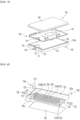
- FIG. 1 is a perspective view of an example of an electronic control unit according to the present invention
- FIG. 2 is a partially cut away perspective view of an example of an electronic control unit according to the present invention
- FIG. 3 is an exploded perspective view of an example of the first control unit shown in FIG. 1
- FIG. 4 is an exploded perspective view of the first coolant jacket shown in FIG. 3 .
- the electronic control unit may comprise at least one control unit. It is possible for the at least one control unit to comprise only one first control unit 1, and it is also possible to further comprise at least one additional control unit besides the first control unit 1.
- FIGs 1 to 4 show a case where the electronic control unit comprises only one first control unit 1.
- the first control unit 1 comprises a first coolant jacket 2, a first flow valve 3, a first case 4, a first control board 5, a second case 6, and a second control board 7.
- An example of the first control unit 1 is an autonomous driving control unit capable of performing autonomous driving of level 2, or an infotainment control unit capable of performing vehicle infotainment (i.e. executing software or operating media to add entertainment in delivering information to a driver and/or a passenger) or a dual control unit that can perform autonomous driving and infotainment simultaneously.
- an autonomous driving control unit capable of performing autonomous driving of level 2
- an infotainment control unit capable of performing vehicle infotainment (i.e. executing software or operating media to add entertainment in delivering information to a driver and/or a passenger) or a dual control unit that can perform autonomous driving and infotainment simultaneously.
- the first coolant jacket 2 is a coolant jacket that can cool the first control board 5 and the second control board 7.
- the coolant flowing in the first coolant jacket 2 may be water but different kinds of coolants may be used instead.
- An inlet 21 and an outlet 22 may be formed in the first coolant jacket 2, and a coolant flow path 23 through which coolant passes and a plurality of cooling fins 24 may be formed inside the first coolant jacket 2.
- the first coolant jacket 2 may have a length in the front-rear direction X, a width in the left-right direction Y, and a thickness in the up-down direction Z.
- the first coolant jacket 2 may comprise a jacket body 25 (hereinafter referred to as the first jacket body) and a cover 26 (hereinafter referred to as the first cover).
- the inlet 21, the outlet 22, the coolant flow path 23, and the cooling fin 24 may be formed in the first jacket body 25.
- the inlet 21 may be formed at one end portion of the first jacket body 25 in the longitudinal direction X of the first jacket body 25, and the outlet 22 may be formed at the other end portion of the first jacket body 25 in the longitudinal direction X of the first jacket body 25.
- the coolant flow path 23 may be formed extending inside the first jacket body 25 in the longitudinal direction X of the first jacket body 25.
- the coolant passage 23 may comprise a plurality of unit passages 23A, an inlet passage 23B, and an outlet passage 23C.
- the plurality of cooling fins 24 are heat transfer fins and may be formed to protrude from the first jacket body 25 or be bent from the first jacket body 25.
- the cooling fins 24 can be plate-shaped or column-shaped, and are not limited to the shape as long as it can promote heat transfer.
- One example of the plurality of cooling fins 24 may be formed long in the longitudinal direction X inside the first jacket body 25.
- the plurality of cooling fins 24 may divide the coolant passage 23 into a plurality of passages.
- the plurality of cooling fins 24 may be provided, and the plurality of cooling fins 24 may be spaced apart from each other in the width direction Y of the first jacket body 25.
- the coolant passage 23 may be divided into a plurality of unit passages 23A by the plurality of cooling fins 24.
- a plurality of unit passages 23A may be parallel.
- the plurality of cooling fins 24 may be spaced apart from each of the inlet 21 and the outlet 22.
- the front end of the cooling fin 24 may be spaced apart from the inlet 21, and the rear end of the cooling fin 24 may be spaced apart from the outlet 22.
- the inlet passage 23B may be formed between the inlet 21 and the cooling fin 24, the coolant supplied to the inlet 21 may distributed into a plurality of unit passages.
- the outlet passage 23C may be formed between the outlet 22 and the cooling fin 24, the coolant supplied from a plurality of unit passages may be combined in the outlet passage 23C.
- An upper rib 25a (refer to FIGS. 3 and 4 ) for fitting the first case 4 may protrude from the upper surface of the first jacket body 25.
- a lower rib 25b (refer to FIGS. 3 and 4 ) for fitting the second case 6 may protrude from the lower surface of the first jacket body 25.
- An opening 25c (refer to FIG. 4 ) through which the coolant passage 23 and the plurality of cooling fin 24 can be exposed may be formed on the lower surface of the first jacket body 25.
- the first cover 26 may cover the coolant passage 23 and the plurality of cooling fins 24.
- the first cover 26 may be disposed on the first jacket body 25 to cover the opening 25c.
- the first cover 26 may be fastened to the first jacket body 25 by a fastening member such as a screw or a hook.
- a valve hole 27 through which the valve body 32 of the first flow valve 3 passes may be formed in the first coolant jacket 2.
- the valve hole 27 may be formed at a location closer to the inlet 21 than to the outlet 22.
- the valve hole 27 may face a vertical direction toward the inlet passage 23B.
- valve hole 27 may be formed in the upper plate of the first jacket body 25 and face the upper surface of the first cover 26.
- the valve hole 27 may be formed in the first cover 26 and face the bottom of the upper plate of the first jacket body 25.
- the first coolant jacket 2 may comprise an inlet nipple 28 and an outlet nipple 29.
- a portion of the inlet nipple 28 may be inserted into the inlet 21.
- the coolant may pass through the inside of the inlet nipple 28 and then flow into the inlet passage 23B.
- the internal passage formed inside the inlet nipple 28 may communicate with the inlet passage 23B, and the inlet nipple 28 may be the inlet 21.
- a portion of the outlet nipple 29 may be inserted into the outlet 22.
- the coolant in the outlet passage 23C may flow out through the inside of the outlet nipple 29.
- the internal passage formed inside the outlet nipple 29 may communicate with the outlet passage 23C, and the outlet nipple 29 may be the outlet 22.
- the first coolant jacket 2 may be located between the first control board 5 and the second control board 7 and cools the first control board 5 and the second control board 7 together.
- the first flow valve 3 may control flow of coolant in the coolant passage 23 of the first coolant jacket 2.
- the first flow valve 3 may be disposed in the first coolant jacket 2.
- the first flow valve 3 may be disposed closer to the inlet 21 than to the outlet 22 of the first coolant jacket 2.
- the opening degree of the outlet of the inlet 21 or the opening degree of the outlet of the inlet nipple 28 may be regulated by the first flow valve 3. That is, the first flow valve 3 may be a flow control valve that regulates the flow rate of coolant.
- the first flow valve 3 may be disposed inside the first control unit 1. That is, the first control unit 1 may be a valve-embedded control unit.
- the first flow valve 3 may comprise a valve housing 31 and a valve body 32.
- the valve housing 31 may be placed inside the first case 4 or the inside of the second case 6.
- a space in which the valve body 32 is accommodated may be formed inside the valve housing 31.
- valve housing 31 is disposed on the upper portion of the first coolant jacket 2, the valve housing 31 may be accommodated in the space S1 formed inside the first case 4, and the valve housing 31 may penetrate the through hole 51 formed in the first control board 5.
- valve housing 31 If the valve housing 31 is disposed in the lower portion of the first coolant jacket 2, the valve housing 31 may be accommodated in the space S2 formed inside the second case 6, and the valve housing 31 may penetrate the through hole 71 formed in the second control board 7.
- the valve body 32 may be disposed to be raised or lowered inside the valve housing 31 and the coolant passage 23 of the first coolant jacket 2.
- valve body 32 may be raised and inserted into the space of the valve housing 31, and may be lowered and positioned in the coolant passage 23.
- valve body 32 can be raised and positioned in the coolant passage 23, and may be lowered and inserted into the space of the valve housing 31.
- the first flow valve 3 may further comprise a driving source (not shown).
- the drive source can raise and lower the valve body 32.
- An example of a driving source may comprise a motor having a rotating shaft.
- Examples of the drive source may further comprise power transmission members such as a worm gear and a worm wheel that convert the rotational motion of the rotation shaft into the reciprocating motion of the valve body 32.
- the driving source may adjust the height of the valve body 32 to adjust the opening degree of the coolant passage 23, especially the inlet passage 23b.
- the driving source can adjust the height of the valve body 32 in multiple stages, and the first flow valve 3 can be an opening control valve or a flow control valve.
- the driving source may be connected to either the first control board 5 or the second control board 7 with a wire or the like, and may be controlled by the first control board 5 or the second control board 7.
- the driving source may be electrically connected to the first control board 5 and may be controlled by the first control board 5.
- the drive source may be electrically connected to the second control board 7 and may be controlled by the second control board 7.
- the first case 4 may be disposed on the upper side of the first coolant jacket 2.
- a space (S1, upper space) in which the first control board 5 is accommodated may be formed inside the first case 4.
- the first case 4 may be the top case of the first control unit 1.
- the first case 4 may form the upper appearance of the first control unit 1.
- the bottom of the first case 4 may be open.
- the edge of the first case 4 may be aligned with the upper rib 25a and may be seated on the upper surface of the first coolant jacket 2.
- the first case 4 may be coupled to the first coolant jacket 2 by a fastening member such as a screw or a hook.
- the first control board 5 may be accommodated in the space S1 formed between the first coolant jacket 2 and the first case 4.
- a through hole (51 or 71) through which the valve housing 31 of the first flow valve 3 penetrates may be formed in at least one of the first control board 5 or the second control board 7.
- An upper through hole 51 may be formed in the first control board 5, a lower through hole 71 may be formed in the second control board 7, and the valve housing 31 may penetrate one of an upper through hole 51 and the lower through hole 71.
- the first control board 5 may be an autonomous driving board for a vehicle.
- the first control board 5 may comprise a semiconductor chip 52 such as an MCU that can perform autonomous driving of the vehicle.
- the first control board 5 may be a control board capable of at least partially performing autonomous driving of level 2.
- the first control board 5 may be equipped with a temperature sensor capable of detecting the temperature of the first control board 5, particularly the temperature of the substrate or the temperature of the semiconductor chip 52, and may be configured to output a control signal to the driving source of the flow valve 3 according to the temperature detected by the temperature sensor.
- the second case 6 may be disposed below the first coolant jacket 2.
- a space (S2, lower space) in which the second control board 7 is accommodated may be formed inside the second case 6.
- the second case 6 may be the bottom case of the first control unit 1.
- the second case 6 may form the bottom appearance of the first control unit 1.
- the top of the second case 6 may be open.
- the edge of the second case 6 may be aligned with the lower rib 25b and may be in contact with the lower surface of the first coolant jacket 2.
- the second case 6 may be coupled to the first coolant jacket 2 by a fastening member such as a screw or a hook.
- the second control board 7 may be accommodated in the space S2 formed between the first coolant jacket 2 and the second case 6.
- the second control board 7 may be, preferably vertically, spaced apart from the first control board 5 with the first coolant jacket 2 therebetween.
- the second control board 7 may be an infotainment board of a vehicle.
- the second control board 7 may comprise a semiconductor chip 72 such as an MCU that controls media such as audio/image/video through media devices installed in the vehicle.
- the second control board 7 may be equipped with a temperature sensor capable of detecting the temperature of the second control board 7, in particular, the temperature of the substrate or the temperature of the semiconductor chip 72, and may be configured to output a control signal to the driving source of the flow valve 3 according to the temperature detected by the temperature sensor.
- the first control unit 1 may further comprise a thermal pad (not shown, hereinafter referred to as a first thermal pad) disposed between the upper surface of the first coolant jacket 2 and the lower surface of the first control board 5.
- a thermal pad not shown, hereinafter referred to as a first thermal pad
- the lower surface of the first control board 5 or the semiconductor chip 52 provided on the first control board 5 may be in direct contact with the upper surface of the first coolant jacket 2, and the first thermal pad may be used to make thermal contact with the upper surface of the coolant jacket 2.
- the first control unit 1 may further comprise a thermal pad (not shown, referred to as a second thermal pad) disposed between the lower surface of the first coolant jacket 2 and the upper surface of the second control board 7.
- a thermal pad not shown, referred to as a second thermal pad
- the upper surface of the second control board 7 or the semiconductor chip 72 provided on the second control board 7 may be in direct contact with the lower surface of the first coolant jacket 2, and the second thermal pad may be used to make thermal contact with the lower surface of the coolant jacket 2.
- FIG. 5 is a perspective view of another example of an electronic control unit according to the present invention
- FIG. 6 is a partially cut away perspective view of another example of an electronic control unit according to the present invention
- FIG. 7 is an exploded perspective view of an example of the second control unit shown in FIG. 5
- FIG. 8 is an exploded perspective view of the second coolant jacket shown in FIG. 7 .
- At least one control unit may be provided in plurality, and the plurality of control units may comprise the first control unit 1 and a second control unit 101 is disposed above the upper side or below side of the first control unit 1.
- the first control unit 1 may be a base module or a module that is basically mounted on a vehicle.
- the second control unit 101 may be an expanded module that extends to the base module, and may be additionally installed depending on the vehicle specifications.
- the first control unit 1 and the second control unit 101 can be stacked in the up-down direction Z.
- the first control unit 1 may be the same as the first control unit 1 of an example of an electronic control unit according to the present invention, and hereinafter, to avoid duplicate description, the same symbols are used and description thereof is omitted.
- the second control unit 101 may be an upper control unit disposed above the first control unit 1 or a lower control unit disposed below the first control unit 1.
- the second control unit 101 may comprise a second coolant jacket 102, a second flow valve 103, a third case 104, and a third control board 105.
- An example of the second control unit 101 may be an autonomous driving control unit capable of executing conditional autonomous driving, which is level 3 of the autonomous driving levels.
- the second coolant jacket 102 may be a coolant jacket that can cool the third control board 105 by water cooling from the upper or lower side of the third control board 105.
- the second coolant jacket 102 may be disposed above the first control unit 1 and below the third control board 105, may be disposed between the first control unit 1 and the third control board 105, and may be arranged to receive both the heat of the first control board 5 and the heat of the third control board 105. In this scence, the second coolant jacket 102 may directly contact the first control board 5 or indirectly contact the first control board 5 via another element, such as the first case 4 or a thermal pad covering the first control board 5, for heat transfer from the first control board 5 to the second coolant jacket 102.
- the second coolant jacket 102 may be disposed below the first control unit 1 and above the third control board 105, may be disposed between the first control unit 1 and the third control board 105, and may be arranged to receive both the heat of the second control board 7 and the heat of the third control board 105. In this scence, the second coolant jacket 102 may directly contact the second control board 7 or indirectly contact the second control board 7 via another element, such as the second case 6 or a thermal pad covering the second control board 7, for heat transfer from the second control board 7 to the second coolant jacket 102.
- An inlet 121 and an outlet 122 are formed in the second coolant jacket 102, and a coolant passage 123 through which coolant passes and a plurality of cooling fins 124 located in the coolant passage 123 are formed inside the second coolant jacket 102.
- the second coolant jacket 102 may be parallel to the first coolant jacket 2 of the first control unit 1, and comprises the inlet 121, the outlet 122, the coolant passage 123, and the plurality of cooling fins 124 may be the same as the inlet 21, the outlet 22, the coolant passage 23, and the plurality of cooling fin 24 of the first coolant jacket 2, and detailed description is omitted to avoid redundant description.
- the second coolant jacket 102 may be spaced apart from the first coolant jacket 2 in the vertical direction Z.
- the second coolant jacket 102 may comprise a jacket body 125 (hereinafter referred to as second jacket body) and a cover 126 (hereinafter referred to as second cover).
- the inlet 121, the outlet 122, the coolant passage 123, and a plurality of cooling fins 124 may be formed in the second jacket body 125.
- the coolant passage 123 may comprise a plurality of unit passages 123A, an inlet passage 123B, and an outlet passage 123C, like the coolant passage 23 of the first coolant jacket 2.
- the plurality of cooling fins 124 may be provided, and the plurality of cooling fins 124 may be spaced apart from each other in the width direction Y of the second jacket body 125.
- the passage 123 may be divided into a plurality of unit passages 123Aby the plurality of cooling fins 124.
- the plurality of unit passages 123A may be parallel.
- the inlet passage 123B may be formed between the inlet 121 and the plurality of cooling fins 124 through which the coolant supplied to the inlet 121 is distributed into a plurality of unit passages 123A.
- the outlet passage 123C may be formed between the outlet 122 and the plurality of cooling fins 124 and the coolant supplied from a plurality of unit passages 123A may be combined in the outlet passage 123C.
- An upper rib 125a (refer to FIGS. 7 and 8 ) for fitting the third case 104 may protrude from the upper surface of the second jacket body 125.
- An opening 125c (refer to FIG. 8 ) through which the coolant passage 123 and the cooling fin 124 can be exposed may be formed on the lower surface of the second jacket body 125.
- the second cover 126 may cover the coolant passage 123 and the plurality of cooling fins 124.
- the second cover 126 may be disposed on the second jacket body 125 to cover the opening 125c.
- the second cover 126 may be fastened to the second jacket body 125 by a fastening member such as a screw or a hook.
- a valve hole 127 through which the valve body 132 of the second flow valve 103 passes may be formed in the second coolant jacket 102.
- the valve hole 127 may be formed at a location closer to the inlet 121 than to the outlet 122.
- the valve hole 127 may face a vertical direction toward the inlet passage 123B.
- valve hole 127 may be formed on the upper plate of the second jacket body 125 and face the upper surface of the second cover 126.
- valve hole 127 may be formed in the second cover 126 and face the bottom of the upper plate of the second jacket body 125.
- the second coolant jacket 102 may comprise an inlet nipple 128 and an outlet nipple 129.
- a portion of the inlet nipple 128 may be inserted into the inlet 121.
- the coolant may pass through the inside of the inlet nipple 128 and then flow into the inlet passage 123B.
- the internal passage formed inside the inlet nipple 128 may communicate with the inlet passage 123B, and the inlet nipple 128 may be the inlet 121.
- a portion of the outlet nipple 129 may be inserted into the outlet 122.
- the coolant in the outlet passage 123C may flow out through the inside of the outlet nipple 129.
- the internal passage formed inside the outlet nipple 129 may communicate with the outlet passage 123C, and the outlet nipple 129 may be the outlet 122.
- the second flow valve 103 may control flow of coolant in the coolant passage 123 of the second coolant jacket 102.
- the second flow valve 103 may comprise a valve housing 131 and a valve body 132.
- the valve housing 131 may be disposed inside the third case 104.
- a space in which the valve body 132 is accommodated may be formed inside the valve housing 131.
- the valve housing 131 may be accommodated in the space S3 formed inside the third case 104 and may penetrate a through hole 151 formed in the third control board 105.
- the valve body 132 may be disposed to be raised or lowered inside the valve housing 131 and the coolant passage 123 of the second coolant jacket 102.
- valve body 132 may be raised and inserted into the space of the valve housing 131, and may be lowered and positioned in the coolant passage 123.
- valve body 132 may be raised and positioned in the coolant passage 123, and may be lowered and inserted into the space of the valve housing 131.
- the second flow valve 103 may further comprise a driving source (not shown).
- the driving source may raise and lower the valve body 132.
- An example of a driving source may comprise a motor having a rotating shaft.
- Examples of the driving source may further comprise power transmission members such as a worm gear and a worm wheel that convert the rotational motion of the rotating shaft into the reciprocating motion of the valve body 132.
- the driving source may adjust the height of the valve body 132 to adjust the opening degree of the coolant passage 123, especially the inlet passage 123b.
- the driving source may adjust the height of the valve body 132 in multiple stages, and the second flow valve 103 may be an opening control valve or a flow control valve.
- the driving source may be connected to the third control board 105 with a wire or the like and may be controlled by the third control board 105.
- the third case 104 may cover the third control board 105.
- the third case 104 may be disposed on the upper side of the second coolant jacket 102.
- the third case 104 may be disposed on the upper or lower side of the second coolant jacket 102.
- a space S3 in which the third control board 105 is accommodated may be formed inside the third case 104.
- the third case 104 may be a top case of the electronic control unit.
- the third case 104 may form the top exterior of the electronic control unit.
- the bottom of the third case 104 may be open.
- the edge of the third case 104 may be aligned with the upper rib 125a of the second coolant jacket 102 and may be seated on the upper surface of the second coolant jacket 102.
- the third case 104 may be a bottom case of the electronic control unit.
- the third case 104 may form the bottom appearance of the electronic control unit.
- the upper surface of the third case 104 may be open.
- the edge of the third case 104 may be aligned with the lower rib (not shown) of the second coolant jacket 102 and may be in contact with the lower surface of the second coolant jacket 102.
- the third case 104 may be coupled to the second coolant jacket 102 by a fastening member such as a screw or a hook.
- the third control board 105 may be disposed in the second coolant jacket 102.
- the third control board 105 may be disposed on the upper or lower surface of the second coolant jacket 102.
- the third control board 105 may be accommodated in the space S3 formed between the second coolant jacket 102 and the third case 104.
- a through hole 151 through which the valve housing 131 of the second flow valve 103 penetrates may be formed in the third control board 105.
- the third control board 105 may be an autonomous driving board for a vehicle.
- the third control board 105 may comprise a semiconductor chip 152 such as an MCU that can perform autonomous driving of the vehicle.
- the third control board 105 may be a control board capable of performing autonomous driving of level 3.
- the third control board 105 may communicate with the first control board 5, and during the level-3 autonomous driving, the semiconductor chip 52 of the first control board 5 and the semiconductor chip 152 of the third control board 105 may also perform calculations for the level-3 autonomous driving.
- a temperature sensor capable of detecting the temperature of the third control board 105, particularly the temperature of the substrate or the temperature of the semiconductor chip 152, may be disposed on the third control board 105, the temperature sensor may output a control signal to the driving source of the flow valve 103 according to the temperature of the substrate or the temperature of the semiconductor chip 152.
- the first control board 5 may output a control signal to the driving source of the first flow valve 3 according to the temperature detected by the temperature sensor installed on the first control board 5, and the third control board 105 may output a control signal to the driving source of the second flow valve 103 according to the temperature detected by the temperature sensor installed on the control board 105.
- the second control unit 101 may further comprise a thermal pad (hereinafter referred to as a third thermal pad) disposed between the second coolant jacket 102 and the third control board 105.
- a thermal pad hereinafter referred to as a third thermal pad
- the coolant flowing through the second coolant jacket 102 may receive the heat of the first control board 5 of the first control unit 1 and the heat of the third control board 105 of the second control unit 101 together, the second control unit 101 may be preferably disposed above the first control unit 1.
- the second coolant jacket 102 of the second control unit 101 may be disposed on the upper side of the first case 4, and the third control board 105 may be preferably in direct contact with the upper surface of the second coolant jacket 102 or in thermal contact through a third thermal pad with the second coolant jacket 102 and the third case 104 is preferably disposed on the upper side of the second coolant jacket 102.
- Another example of the electronic control unit according to the present invention may further comprise an inlet manifold 180 and an outlet manifold 190.
- the inlet manifold 180 may be connected to each of the inlet 21 of the first coolant jacket 2 and the inlet 121 of the second coolant jacket 102.
- the inlet manifold 180 may be connected to the inlet nipple 28 of the first coolant jacket 2 and the inlet nipple 128 of the second coolant jacket 102.
- the outlet manifold 190 may be connected to each of the outlets 22 of the first coolant jacket 2 and the outlets 122 of the second coolant jacket 102.
- the outlet manifold 190 may be connected to each of the outlet nipple 29 of the first coolant jacket 2 and the outlet nipple 129 of the second coolant jacket 102.
- FIG. 9 is a perspective view of the other example of an electronic control unit according to the present invention
- FIG. 10 is a partially cut away perspective view of the other example of an electronic control unit according to the present invention
- FIG. 11 is an exploded perspective view of an example of the third control unit shown in FIG. 9
- FIG. 12 is an exploded perspective view of the third coolant jacket shown in FIG. 11 .
- the other example of the electronic control unit according to the present invention is that at least one control unit may be provided in plurality, and the plurality of control units may comprise the first control unit 1, the second control units 101 disposed above the first control unit 1 and a third control unit 201 disposed below the first control unit 1.
- the first control unit 1 may be a base module or a module that is basically mounted on the vehicle.
- the second control unit 101 and the third control unit 201 may be expanded modules that extend to the base module, and may be additionally installed according to the specifications of the vehicle.
- the first control unit 1, the second control unit 101, and the third control unit 201 may be stacked in the up-down direction Z.
- the first control unit 1 may be disposed between the second control unit 101 and the third control unit 201.
- the first control unit 1 may be the same as the first control unit 1 of an example of an electronic control unit according to the present invention, and hereinafter, to avoid duplicate description, the same symbols are used and description thereof is omitted.
- the second control unit 101 may be the same as the second control unit 101 of another example of the electronic control unit according to the present invention, and hereinafter, to avoid duplicate description, the same symbols are used and description thereof is omitted.
- Each of the second control unit 101 and the third control unit 201 comprises a coolant jacket having a coolant passage through which coolant passes and a flow valve that opens and closes the coolant passage.
- the third control unit 201 may be spaced apart from the second control unit 101 in the vertical direction.
- the third control unit 201 may be a lower control unit disposed below the first control unit 1.
- the third control unit 201 may comprise a third coolant jacket 202, a third flow valve 203, a fourth case 204, and a fourth control board 205.
- An example of the third control unit 201 may be an autonomous driving control unit capable of executing high autonomous driving, which is level 4 of the autonomous driving levels.
- the third coolant jacket 202 may be a coolant jacket that can cool the fourth control board 205 by water cooling on the upper side of the fourth control board 205.
- the third coolant jacket 202 may be disposed below the first control unit 1 and above the fourth control board 205, and may be disposed between the first control unit 1 and the fourth control board.
- the third coolant jacket 202 may dissipate the heat of the second control board 7 and the heat of the fourth control board 205 together.
- An inlet 221 and an outlet 222 are formed in the third coolant jacket 202, and a coolant passage 223 through which coolant passes and a plurality of cooling fins 224 are formed inside the third coolant jacket 202.
- the third coolant jacket 202 may be parallel to the first coolant jacket 2 of the first control unit 1, and comprises the inlet 221, the outlet 222, the coolant passage 223, and the plurality of cooling fins 224 may be the same as the inlet 21, the outlet 22, the coolant passage 23, and the plurality of cooling fins 24 of the first coolant jacket 2, and detailed description is omitted to avoid redundant description.
- the third coolant jacket 202 may be spaced apart from the first coolant jacket 2 in the vertical direction Z.
- the third coolant jacket 202 may comprise a jacket body 225 (hereinafter referred to as the third jacket body) and a cover 226 (hereinafter referred to as the third cover).
- the inlet 221, the outlet 222, the coolant passage 223, and the plurality of cooling fins 224 may be formed in the third jacket body 225.
- the coolant passage 223 may comprise a plurality of unit passages 223A, an inlet passage 223B, and an outlet passage 223C, like the coolant passage 23 of the first coolant jacket 2.
- a plurality of cooling fins 224 may be provided, and the plurality of cooling fins 224 may be spaced apart from each other in the width direction Y of the third jacket body 225.
- the coolant passage 223 may be divided into a plurality of unit passages 223 by the plurality of cooling fins 224.
- the plurality of unit passages 223A may be parallel.
- An inlet passage 223B may be formed between the inlet 221 and the plurality of cooling fins 224, through which the coolant supplied to the inlet 221 is distributed into a plurality of unit passages 223A.
- An outlet passage 223C may be formed between the outlet 222 and the plurality of cooling fins 224, in which the coolant flowing in the plurality of unit passages 223A is combined.
- a lower rib 225a (refer to FIGS. 11 and 12 ) for fitting the fourth case 204 may protrude from the lower surface of the third jacket body 225.
- An opening 225c (refer to FIG. 12 ) through which the coolant passage 223 and the plurality of cooling fins 224 can be exposed may be formed on the upper surface of the third jacket body 225.
- the third cover 226 may cover the coolant passage 223 and the plurality of cooling fins 224.
- the third cover 226 may be disposed on the third jacket body 225 to cover the opening 225c.
- the third cover 226 may be fastened to the third jacket body 225 by a fastening member such as a screw or a hook.
- a valve hole through which the valve body 232 of the third flow valve 203 passes may be formed in the third coolant jacket 202.
- the valve hole may be formed at a location closer to the inlet 221 than to the outlet 222.
- the valve hole may face a vertical direction toward the inlet passage 223B.
- valve hole may be formed on the lower plate of the third jacket body 225 and face the third cover 226.
- Another example of the valve hole may be formed in the third cover 226 and face the bottom of the lower plate of the third jacket body 225.
- the third coolant jacket 202 may comprise an inlet nipple 228 and an outlet nipple 229.
- a portion of the inlet nipple 228 may be inserted into the inlet 221.
- the coolant may pass through the inside of the inlet nipple 228 and then flow into the inlet passage 223B.
- the internal passage formed inside the inlet nipple 228 may communicate with the inlet passage 223B, and the inlet nipple 228 may be the inlet 221.
- a portion of the outlet nipple 229 may be inserted into the outlet 222.
- the coolant in the outlet passage 223C may flow out through the inside of the outlet nipple 229.
- the internal passage formed inside the outlet nipple 229 may communicate with the outlet passage 223C, and the outlet nipple 229 may be the outlet 222.
- the third flow valve 203 can control the coolant passage 223 of the third coolant jacket 202.
- the third flow valve 203 may comprise a valve housing 231 and a valve body 232.
- the valve housing 231 may be disposed inside the fourth case 204.
- a space in which the valve body 232 is accommodated may be formed inside the valve housing 231.
- the valve housing 231 may be accommodated in the space S4 formed inside the fourth case 204 and may penetrate the through hole 251 formed in the fourth control board 205.
- the valve body 232 may be disposed to be raised or lowered inside the valve housing 231 and the coolant passage 223 of the third coolant jacket 202.
- valve body 232 may be raised and positioned in the coolant passage 223, and may be lowered and inserted into the space of the valve housing 231.
- the third flow valve 203 may further comprise a driving source (not shown).
- the drive source can raise or lower the valve body 232.
- An example of a driving source may comprise a motor having a rotating shaft.
- Examples of the drive source may further comprise power transmission members such as a worm gear and a worm wheel that convert the rotational motion of the rotation shaft into the reciprocating motion of the valve body 232.
- the driving source may adjust the height of the valve body 232 to adjust the opening degree of the coolant passage 223, especially the inlet passage 223b.
- the driving source may adjust the height of the valve body 232 in multiple stages, and the third flow valve 203 may be an opening control valve or a flow control valve.
- the driving source may be connected to the fourth control board 205 with a wire or the like and may be controlled by the fourth control board 205.
- the fourth case 204 may cover the fourth control board 205.
- the fourth case 204 may be disposed below the third coolant jacket 202.
- a space S4 in which the fourth control board 205 is accommodated may be formed inside the fourth case 204.
- the fourth case 204 When the fourth case 204 is disposed below the third coolant jacket 202, the fourth case 204 may be a bottom case of the electronic control unit. The fourth case 204 may form the bottom exterior of the electronic control unit. The upper surface of the fourth case 204 may be open. The edge of the fourth case 204 may be aligned with the lower rib 225a of the third coolant jacket 202 and may be in contact with the lower surface of the third coolant jacket 202.
- the fourth case 204 may be coupled to the third coolant jacket 202 by a fastening member such as a screw or a hook.
- the fourth control board 205 may be disposed below the third coolant jacket 202.
- the fourth control board 201 may be disposed on the lower surface of the third coolant jacket 202.
- the fourth control board 205 may be accommodated in the space S4 formed between the third coolant jacket 202 and the fourth case 204.
- a through hole 251 through which the valve housing 231 of the third flow valve 203 penetrates may be formed in the fourth control board 205.
- An example of the fourth control board 205 may be an autonomous driving board for a vehicle.
- the fourth control board 205 may comprise a semiconductor chip 252 such as an MCU that can perform autonomous driving of the vehicle.
- the fourth control board 205 may be a control board capable of perform autonomous driving of level 4.
- the fourth control board 205 can communicate with at least one of the first control board 5 or the third control board 105, and during the level-4 autonomous driving, the semiconductor chip 252 of the fourth control board 205 may perform calculations for the level-4 autonomous driving together with at least one of the semiconductor chip 52 of the first control board 5 or the semiconductor chips 152 of the third control board 105.
- a temperature sensor capable of detecting the temperature of the fourth control board 205, particularly the temperature of the substrate or the temperature of the semiconductor chip 252, may be disposed on the fourth control board 205, and the temperature sensor may output a control signal to the driving source of the flow valve 203 according to the temperature detected by the temperature sensor.
- the first control board 5 may output a control signal to the driving source of the first flow valve 3 according to the temperature detected by the temperature sensor installed on the first control board 5
- the third control board 105 may output a control signal to the driving source of the second flow valve 1033 according to the temperature detected by the temperature sensor installed on the third control board 105
- the fourth control board 205 may output a control signal to the driving source of the third flow valve 203 according to the temperature detected by the temperature sensor installed on the fourth control board 205.
- the third control unit 201 may further comprise a thermal pad (hereinafter referred to as a fourth thermal pad) disposed between the third coolant jacket 202 and the fourth control board 205.
- a thermal pad hereinafter referred to as a fourth thermal pad
- the coolant flowing through the third coolant jacket 202 may be preferably to cool the second control board 7 of the first control unit 1, and the fourth control board 205 of the third control unit 201 together, in case where the third control unit 201 is preferably disposed below the first control unit 1.
- the other example of the electronic control unit according to the present invention may further comprise an inlet manifold (180') and an outlet manifold (190').
- the inlet manifold 180' is connected to each of the inlet 21 of the first coolant jacket 2, the inlet 121 of the second coolant jacket 102, and the inlet 221 of the third coolant jacket 202.
- the inlet manifold 180' is connected to the inlet nipple 28 of the first coolant jacket 2, the inlet nipple 128 the second coolant jacket 102 and the inlet nipple 228 of the third coolant jacket 202, respectively.
- the outlet manifold 190' is connected to each of the outlets 22 of the first coolant jacket 2, the outlets 122 of the second coolant jacket 102, and the outlets 222 of the third coolant jacket 202.
- the outlet manifold 190' is connected to the outlet nipple 29 of the first coolant jacket 2, the outlet nipple 129 of the second coolant jacket 102 and the outlet nipple 229 of the third coolant jacket 202, respectively.
- a coolant passage through which coolant can flow is formed in each of the plurality of control units 1, 101 and 201, the plurality of cooling fins are installed parallel to the direction of coolant flowing to promote conductive heat transfer in the coolant passage, and the coolant performs a cooling function targeting the first control board 5, second control board 7, third control board 105, and fourth control board 205 after the coolant flow into each coolant passage.
- the coolant may be combined and may flow out of the electronic control unit after performing the cooling function.
- the flow valve mounted on the inlet passage of each of the plurality of control units 1, 101 and 201 may receive signal from the MCU mounted on the control board of each of the plurality of control units 1, 101 and 201 and may be actively controlled to prevent the temperature of the high-heating element from exceeding the allowable temperature.
- the operation workload of the plurality of control units 1, 101 and 201 may be different depending on the type of function performed, and if there are differences in the amount of heat generated for each control unit, the flow rate of coolant provided to cool a low heat generation control unit may be reduced through control of a flow valve, and the flow rate of coolant provided to cool a high heat control unit may be reduced through control of another flow valve, and thereby a more efficient cooling function of the plurality of control units 1, 101 and 201 may be performed.
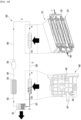
- FIG. 13 is an enlarged view of the flow valves when all flow valves shown in FIG. 10 are open.
- Each of the first control board 5, the third control board 105, and the fourth control board 205 may control each of the driving source of the first flow valve 3, the driving source of the second flow valve 103 and the driving source of the third flow valve 3 according to temperatures detected by a temperature sensor provided in each of first control board 5, the third control board 105, and the fourth control board 205.
- the first control board 5 may control the driving source of the first flow valve 3 in an open mode
- the third control board 105 may control the driving source of the second flow valve 103 in an open mode
- the fourth control board 205 can control the driving source of the third flow valve 203 in an open mode.
- the coolant may be dispersed and flow in all of the first, second, and third coolant jackets 2, 102 and 202, the first control board 5, and the second control board 7, the third control board 105 and the fourth control board 205 may be cooled together.
- FIG. 14 is an enlarged view of the flow valves when the first control unit shown in FIG. 10 generates heat.
- the temperature detected by the temperature sensor provided in the first control board 5 is above the preset cooling temperature, and the temperature detected by the temperature sensors provided in each of the third control board 105 and the fourth control board 205 is below the preset cooling temperature, the first control board 5 may control the driving source of the first flow valve 3 in an open mode, the third control board 105 may control the driving source of the second flow valve 103 in a closed mode, and the fourth control board 205 may control the driving source of the third flow valve 203 in a closed mode.
- coolant is supplied only to the first coolant jacket 2, and is not supplied to the second coolant jacket 102 and the third coolant jacket 202, and the first control board 5 and the second control board 7 can be cooled.
- FIG. 15 is an enlarged view of the flow valves when the second control unit shown in FIG. 10 generates heat.
- the temperature detected by the temperature sensor provided in the third control board 105 is above the preset cooling temperature, and the temperature detected by the temperature sensors provided in each of the first control board 5 and the fourth control board 205 is below the preset cooling temperature, the first control board 5 may control the driving source of the first flow valve 3 in a close mode, the third control board 105 may control the driving source of the second flow valve 103 in an open mode, and the fourth control board 205 can control the driving source of the third flow valve 203 in a closed mode.
- coolant is supplied only to the second coolant jacket 102, and is not supplied to the first coolant jacket 2 and the third coolant jacket 202, and the third control board 105 and the first control board 5 may be cooled.
- FIG. 16 is an enlarged view of the flow valves when the third control unit shown in FIG. 10 generates heat.
- the temperature detected by the temperature sensor provided in the fourth control board 205 is above the preset cooling temperature, and the temperature detected by the temperature sensors provided in each of the first control board 5 and the third control board 105 is below the preset cooling temperature, the first control board 5 may control the driving source of the first flow valve 3 in a close mode, the third control board 105 may control the driving source of the second flow valve 103 in a close mode, and the fourth control board 205 may control the driving source of the third flow valve 203 in an open mode.
- coolant is supplied only to the third coolant jacket 202, and is not supplied to the first coolant jacket 2 and the second coolant jacket 102, and the fourth control board 205 and the second board 205 may be cooled.
- FIG. 17 shows a cooling device connected to the electronic control unit according to the present invention.
- the cooling device 300 can circulate cold coolant through the electronic control unit.
- the cooling device 300 may be connected to the electronic control unit through a water pipe.
- the cooling device 300 comprises a heat exchanger 301, a coolant tank 303 connected to the heat exchanger 301 through the heat exchanger outlet pipe 302, and a pump 305 connected to a coolant tank 303 through pump inlet pipe 304, and a pump outlet pipe 306 connecting the pump 305 and the electronic control unit, and the electronic control unit and the heat exchanger 301 may be connected through the heat exchanger inlet pipe 307.
- the heat exchanger 301 can dissipate heat from the coolant into the atmosphere in an air-cooled manner.
- the pump outlet pipe 306 may be connected to the inlet nipple 28 of one example of the electronic control unit or the inlet manifold 180 of another example of the electronic control unit, or the inlet manifold 180' of the other example of the electronic control unit.
- the heat exchanger inlet pipe 307 may be connected to the outlet nipple 29 of one example of the electronic control unit, the outlet manifold 190 of another example of the electronic control unit, or the outlet manifold 190' of the other example of the electronic control unit.
- the coolant may circulate through the heat exchanger 301 and the electronic control unit and dissipate heat in the electronic control unit.
- FIG. 18 shows a cooling device 300' connected to the electronic control unit according to the present invention and a vehicle motor 400.
- the cooling device 300' shown in FIG. 18 can circulate cold coolant through the electronic control unit and the motor 400.
- An example of the motor 400 may be a drive motor provided in an electric vehicle to provide driving force to the wheels.
- the motor 400 may comprise a motor housing 403 in which a coolant inlet port 401 and a coolant outlet port 402 are formed.
- the cooling device 300' may be connected to the electronic control unit and motor 400 through a water pipe.
- the cooling device 300' may comprise a heat exchanger 301, a coolant tank 303 connected to the heat exchanger 301 through a heat exchanger outlet pipe 302, and a pump 305 connected to the coolant tank 303 through a pump inlet pipe 304, a pump outlet pipe 306 connecting the pump 305 and the electronic control unit, and the connection pipe 308 connecting the electronic control unit and the motor 400, and the heat exchange 301 and the motor 400 are connected through a heat exchanger inlet pipe 307'.
- the heat exchanger 301, the heat exchanger outlet pipe 302, the coolant tank 303, the pump inlet pipe 304, the pump 305, and the pump outlet pipe 306 are same with the cooling device 300 as shown in FIG. 17 and its description is omitted to avoid redundant description.
- the heat exchanger inlet pipe 307' may be connected to the coolant outlet port 402 of the motor 400.
- connection pipe 308' may be connected to the electronic control unit, such as the outlet nipple 29 in one example of the electronic control unit or the outlet manifold 190 in another example of the electronic control unit, or the outlet manifold 190' in the other example of the electronic control unit.
- connection pipe 308' may be connected to the coolant inlet port 401 of the motor 400.
- the coolant can circulate through the heat exchanger 301, the electronic control unit, and the motor 400, and can sequentially dissipate heat through the electronic control unit and the motor 400.
- FIG. 19 shows a cooling device 300" connected to the electronic control unit according to the present invention and another kind of electronic control unit 500.
- the cooling device 300" shown in FIG. 19 can circulate cold coolant to the electronic control unit and the additional electronic control unit 500.
- the additional electronic control unit 500 may comprise an additional coolant jacket 503 in which a coolant inlet 501 and a coolant outlet 502 are formed.
- the coolant inlet 501 and the coolant outlet 502 may be formed on a same side of the additional electronic control unit 500.
- An example of the additional electronic control unit 500 may be an electronic control unit provided separately from the electronic control unit of the present invention, and a plurality of additional control units 504, 505, and 506 may be cooled with one additional coolant jacket 503.
- the cooling device 300" may be connected to the electronic control unit and the additional electronic control unit 500 through a water pipe.
- the cooling device 300" may comprise a heat exchanger 301, a coolant tank 303 connected to the heat exchanger 301 and a pump 305 connected to the coolant tank 303 through a pump inlet pipe 304, a pump outlet pipe 305 connecting the pump 304 and the additional electronic control unit 500, and the connection pipe 308" connecting the additional electronic control unit 500 and the electronic control unit, and the electronic control unit and the heat exchanger 301 are connected through the heat exchanger inlet pipe 307.
- One end of the pump outlet pipe 306" may be connected to the outlet of the pump 305.
- the other end of the pump outlet pipe 306" may be connected to the coolant inlet 501 of the additional electronic control unit 500.
- connection pipe 308 may be connected to the coolant outlet 502 of the additional electronic control unit 500.
- connection pipe 308" may be connected to the inlet nipple 28 of one example of the electronic control unit, the inlet manifold 180 of another example of the electronic control unit, or the inlet manifold 180' of the other example of the electronic control unit.
- the coolant may circulate through the heat exchanger 301, the additional electronic control unit 500, and the electronic control unit, and can sequentially dissipate heat through the additional electronic control unit 500 and the electronic control unit.
- the coolant may flow through the passage at a specific flow rate Q by the pump 305, and the coolant may flow into the additional electronic control unit 500, cool the heat source of the additional electronic control unit 500, and then flow out of the additional electronic control unit 500.
- the coolant flow out of the additional electronic control unit 500 may flow into the inlet of the electronic control unit of the present invention, may cool each of heat sources of the plurality of control units 1,101 and 102 connected in parallel, and may flow out of the electronic control unit after combining.
- the temperature of the coolant may return to an initial temperature while passing through the heat exchanger 301, and the coolant may be stored in the coolant tank 303.
- the above process may be repeated for the coolant stored in the coolant tank 303.
- the cooling devices shown in Figs. 17 to 19 are just exemplary devices for supplying coolant to the electronic control unit of the present invention, but different types of cooling devices for supplying coolant can be adopted by a person skilled in the technology of refrigeration cycle.
- the first coolant jacket disposed between the first control board and the second control board can cool the first control board and the second control board together, the structure is simple and compactization is possible compared to the case the first control board and the second control board are cooled by the individual coolant jackets.
- the first coolant jacket comprises a first jacket body and a first cover, it easy to clean or service the coolant flow path or the first flow valve.
- the autonomous driving board of the vehicle and the infotainment board of the vehicle are spaced apart vertically, so when one of the autonomous driving board of the vehicle and the infotainment board of the vehicle breaks down, only a broken board can be replaced or repaired.
- the autonomous driving board vehicle and the infotainment board vehicle can be selectively updated.
- valve housing is penetrated into the through hole formed in at least one of the first control board or the second control board, so the valve housing can be received in the first case together with the first control board, or received in the second control board with the second control board, and it possible to compact the electronic control unit.
- valve body of the first flow valve passes through the valve hole formed in the first coolant jacket, all or part of the valve housing can be located outside the first coolant jacket, and the thickness of the first coolant jacket can be minimized.
- the second control unit may be disposed on the upper or lower surface of the first control unit to expand the electronic control unit, and the second coolant jacket of the second control unit may cool the third control board and the first control board together, the cooling performance of the first control board is high.
- the electronic control unit can be expanded, the second coolant jacket of the second control unit can cool the third control board and the first control board together, and the cooling performance of the first control board is high. And the third coolant jacket of the third control unit can cool the second control board and the fourth control board together, and the cooling performance of the second control board is high.
- the electronic control unit can increase the flow rate of coolant supplied to a control unit containing a low heat source and can decrease the flow rate of coolant supplied to a control unit containing a low heat source, and the electronic control unit can perform an efficient cooling function.
Landscapes
- Engineering & Computer Science (AREA)
- Microelectronics & Electronic Packaging (AREA)
- Physics & Mathematics (AREA)
- Thermal Sciences (AREA)
- Mechanical Engineering (AREA)
- Cooling Or The Like Of Semiconductors Or Solid State Devices (AREA)
- Cooling Or The Like Of Electrical Apparatus (AREA)
Abstract
The electronic control unit according to the present invention comprises at least one control unit. The at least one control unit comprises a first control unit. The first control unit comprises a first coolant jacket in which an inlet and an outlet are formed, a coolant passage through which coolant passes, and a plurality of cooling fins are formed; a first flow valve controlling a coolant passage of the first coolant jacket; a first case disposed above the first coolant jacket; a first control board accommodated in a space formed between the first coolant jacket and the first case; a second case disposed below the first coolant jacket; and a second control board accommodated in a space formed between the first coolant jacket and the second case.
Description
- The present invention relates to an electronic control unit.
- Assemblies installed in a vehicle comprise an engine control assembly (or motor control assembly), power transmission assembly, brake assembly, suspension assembly, steering assembly, instrument assembly, and information and communication control assembly.
- An electronic control unit (ECU) is a control device that has the function of controlling and managing the main assemblies of a vehicle. A number of electronic control units are installed in the vehicle depending on the assembly to control each assembly.
- The electronic control unit may comprise an electronic control unit with a built-in chip for autonomous driving or infotainment (software or media that adds entertainment to the transfer of information) installed in the vehicle, and it is desirable for the chip or the board (control board) on which the chip is installed to be properly cooled to prevent overheating of the chip.
- An example of an electronic control unit being cooled is an electronic module disclosed in
U.S. Patent Publication No. US 5323292 A (Patent, on June 21, 1994 ). The electronic module comprises an aluminum heat sink surrounding an integrated circuit chip and a substrate, and the aluminum heat sink comprises parallel fins that provide a larger surface area to dissipate heat into the surrounding atmosphere. - The purpose of this embodiment is to provide an electronic control unit that can cool a plurality of control boards more efficiently.
- The purpose of this embodiment is to provide an electronic control unit that can efficiently cool the control boards of each of the plurality of control units even if the number of control units increases.
- The electronic control unit according to this embodiment comprises at least one control unit. The at least one control unit comprises a first control unit. The first control unit comprises a first coolant jacket comprising an inlet for introducing coolant into the first coolant jacket, an outlet for discharging the coolant from the first coolant jacket, a coolant passage through which the introduced coolant flows, and a plurality of cooling fins disposed in the coolant passage for heat exchange with the coolant; a first flow valve configured to control flow of the coolant in the coolant passage of the first coolant jacket; a first case disposed above the first coolant jacket; a first control board accommodated in a space formed between the first coolant jacket and the first case and arranged to transfer heat generated at the first control board into the first coolant jacket. The first control unit further comprises a second case disposed below the first coolant jacket; and a second control board accommodated in a space formed between the first coolant jacket and the second case and arranged to transfer heat generated at the second control board into the first coolant jacket. The coolant may be water but not limited to that.
- The first coolant jacket may comprise a first jacket body in which the inlet, the outlet, the coolant passage and the plurality of cooling fins are formed, and a first cover coupled to the jacket body and covering the coolant passage and plurality of cooling fins.
- The first control unit may further comprise a thermal pad disposed between an upper surface of the first coolant jacket and a lower surface of the first control board.
- The first control unit may further comprise a thermal pad disposed between a lower surface of the first coolant jacket and an upper surface of the second control board.
- The first control board may be an autonomous driving board of a vehicle, and the second control board may be an infotainment board of the vehicle. In other words, the first control board may comprise at least one semiconductor chip configured to execute program codes for autonomous driving of a vehicle, and the second control board may comprise at least one semiconductor chip configured to execute program codes for control of media devices in the vehicle.
- The first control board and the second control board may be spaced apart, in particular vertically, and the first coolant jacket may be interposed between the first control board and the second control board.
- The first flow valve may comprise a valve housing; a valve body disposed to be raised or lowered within the valve housing and into the coolant passage of the first coolant jacket; and a driving source configured to raise or lower the valve body.
- A through hole through which the valve housing passes may be formed in at least one of the first control board or the second control board.
- A valve hole through which the valve body passes may be formed in the first coolant jacket.
- The at least one control unit may further comprise a second control unit disposed above or below the first control unit.
- The second control unit may comprise a second coolant jacket including an inlet for introducing the coolant into the second coolant jacket, an outlet for discharging the coolant from the second coolant jacket, a coolant passage through which the introduced coolant flows, and a plurality of cooling fins disposed in the coolant passage for heat exchange with the coolant; a second flow valve configured to control flow of the coolant in the coolant passage of the second coolant jacket; a third control board disposed on the second coolant jacket to transfer heat generated at the third control board into the second coolant jacket; and a third case covering the third control board.
- The second coolant jacket may comprise a second jacket body in which the inlet and the outlet, the coolant passage and the plurality of cooling fins are formed; and a second cover covering the coolant passage and the plurality of cooling fins.
- The second control unit may comprise a thermal pad disposed between the second coolant jacket and the third control board.
- The second flow valve may comprise a valve housing; a valve body disposed to be raised or lowered within the valve housing and into the coolant passage of the second coolant jacket; and a driving source configured to raise and lower the valve body.
- A through hole through which the valve housing passes may be formed in the third control board.
- A valve hole through which the valve body passes may be formed in the second coolant jacket.
- The electronic control unit may further comprise an inlet manifold connected to each of the inlet of the first coolant jacket and the inlet of the second coolant jacket; and an outlet manifold connected to each of the outlet of the first coolant jacket and the outlet of the second coolant jacket.
- The at least one control unit may comprise a third control unit spaced apart from the second control unit.
- The third control unit may comprise a third coolant jacket comprising an inlet for introducing the coolant into the third coolant jacket, an outlet for discharging the coolant from the third coolant jacket, a coolant passage through which the introduced coolant flowes, and a plurality of cooling fins disposed in the third coolant passage for heat exchange with the coolant; a third flow valve configured to control flow of the coolant in the coolant passage of the third coolant jacket; a fourth control board disposed on the third coolant jacket to transfer heat generated at the fourth control board into the third coolant jacket; and a fourth case covering the fourth control board.
- The third coolant jacket may comprise a third jacket body in which the inlet, the outlet, the coolant passage, and the plurality of cooling fins are formed; and a third cover covering the coolant passage and the plurality of cooling fins.
- The third control unit may comprise a thermal pad disposed between the third coolant jacket and the fourth control board.
- The third flow valve may comprise a valve housing; a valve body disposed to be raised or lowered within the valve housing and into the coolant passage of the third coolant jacket; and a driving source configured to raise or lower the valve body,
- A through hole through which the valve housing passes may be formed in the fourth control board.
- A valve hole through which the valve body passes may be formed in the third coolant jacket.
- The electronic control unit may further comprise an inlet manifold connected to each of the inlet of the first coolant jacket, the inlet of the second coolant jacket, and the inlet of the third coolant jacket; and an outlet manifold connected to each of the outlet of the first coolant jacket, the outlet of the second coolant jacket, and the outlet of the coolant jacket.
- The electronic control unit may further comprise a second control unit; and a third control unit spaced apart from the second control unit.
- The second control unit may comprise a second coolant jacket disposed above the first control unit and having a coolant passage through which coolant passes, a second flow valve that opens or closes the coolant passage of the second coolant jacket; and a third control board cooled by the second coolant jacket. The third control unit comprises a third coolant jacket disposed below the first control unit and having a coolant passage through which the coolant passes; a third flow valve that opens or closes the coolant passage of the third coolant jacket, and a fourth control board cooled by the third coolant jacket.
-
-
FIG. 1 is a perspective view of an example of an electronic control unit according to the present invention; -
FIG. 2 is a partially cut away perspective view of an example of an electronic control unit according to the present invention; -
FIG. 3 is an exploded perspective view of an example of the first control unit shown inFIG. 1 ; -
FIG. 4 is an exploded perspective view of the first coolant jacket shown inFIG. 3 ; -
FIG. 5 is a perspective view of another example of an electronic control unit according to the present invention; -
FIG. 6 is a partially cut away perspective view of another example of an electronic control unit according to the present invention; -
FIG. 7 is an exploded perspective view of an example of the second control unit shown inFIG. 5 ; -
FIG. 8 is an exploded perspective view of the second coolant jacket shown inFIG. 7 ; -
FIG. 9 is a perspective view of the other example of an electronic control unit according to the present invention; -
FIG. 10 is a partially cut away perspective view of the other example of an electronic control unit according to the present invention; -
FIG. 11 is an exploded perspective view of an example of the third control unit shown inFIG. 9 ; -
FIG. 12 is an exploded perspective view of the third coolant jacket shown inFIG. 11 ; -
FIG. 13 is an enlarged view of the flow valves when all flow valves shown inFIG. 10 are open; -
FIG. 14 is an enlarged view of the flow valves when the first control unit shown inFIG. 10 generates heat; -
FIG. 15 is an enlarged view of the flow valves when the second control unit shown inFIG. 10 generates heat; -
FIG. 16 is an enlarged view of the flow valves when the third control unit shown inFIG. 10 generates heat; -
FIG. 17 is a view of a cooling device connected to the electronic control unit of the present invention; -
FIG. 18 is a view of another cooling device connected to the electronic control unit of the present invention and a vehicle motor; and -
FIG. 19 is a view of another cooling device connected to the electronic control unit of the present invention and an additional electronic control unit. - Hereinafter, detailed embodiments will be described in detail with reference to the accompanying drawings.
-
FIG. 1 is a perspective view of an example of an electronic control unit according to the present invention;FIG. 2 is a partially cut away perspective view of an example of an electronic control unit according to the present invention;FIG. 3 is an exploded perspective view of an example of the first control unit shown inFIG. 1 ; andFIG. 4 is an exploded perspective view of the first coolant jacket shown inFIG. 3 . - The electronic control unit may comprise at least one control unit. It is possible for the at least one control unit to comprise only one
first control unit 1, and it is also possible to further comprise at least one additional control unit besides thefirst control unit 1. -
FIGs 1 to 4 show a case where the electronic control unit comprises only onefirst control unit 1. - The
first control unit 1 comprises afirst coolant jacket 2, afirst flow valve 3, afirst case 4, afirst control board 5, asecond case 6, and asecond control board 7. - An example of the
first control unit 1 is an autonomous driving control unit capable of performing autonomous driving oflevel 2, or an infotainment control unit capable of performing vehicle infotainment (i.e. executing software or operating media to add entertainment in delivering information to a driver and/or a passenger) or a dual control unit that can perform autonomous driving and infotainment simultaneously. - The
first coolant jacket 2 is a coolant jacket that can cool thefirst control board 5 and thesecond control board 7. The coolant flowing in thefirst coolant jacket 2 may be water but different kinds of coolants may be used instead. - An
inlet 21 and anoutlet 22 may be formed in thefirst coolant jacket 2, and acoolant flow path 23 through which coolant passes and a plurality of coolingfins 24 may be formed inside thefirst coolant jacket 2. - The
first coolant jacket 2 may have a length in the front-rear direction X, a width in the left-right direction Y, and a thickness in the up-down direction Z. - The
first coolant jacket 2 may comprise a jacket body 25 (hereinafter referred to as the first jacket body) and a cover 26 (hereinafter referred to as the first cover). - As shown in
FIG. 4 , theinlet 21, theoutlet 22, thecoolant flow path 23, and the coolingfin 24 may be formed in thefirst jacket body 25. - The
inlet 21 may be formed at one end portion of thefirst jacket body 25 in the longitudinal direction X of thefirst jacket body 25, and theoutlet 22 may be formed at the other end portion of thefirst jacket body 25 in the longitudinal direction X of thefirst jacket body 25. - The
coolant flow path 23 may be formed extending inside thefirst jacket body 25 in the longitudinal direction X of thefirst jacket body 25. - The
coolant passage 23 may comprise a plurality ofunit passages 23A, aninlet passage 23B, and anoutlet passage 23C. - The plurality of cooling
fins 24 are heat transfer fins and may be formed to protrude from thefirst jacket body 25 or be bent from thefirst jacket body 25. The coolingfins 24 can be plate-shaped or column-shaped, and are not limited to the shape as long as it can promote heat transfer. - One example of the plurality of cooling
fins 24 may be formed long in the longitudinal direction X inside thefirst jacket body 25. The plurality of coolingfins 24 may divide thecoolant passage 23 into a plurality of passages. - The plurality of cooling
fins 24 may be provided, and the plurality of coolingfins 24 may be spaced apart from each other in the width direction Y of thefirst jacket body 25. Thecoolant passage 23 may be divided into a plurality ofunit passages 23A by the plurality of coolingfins 24. A plurality ofunit passages 23A may be parallel. - The plurality of cooling
fins 24 may be spaced apart from each of theinlet 21 and theoutlet 22. - The front end of the cooling
fin 24 may be spaced apart from theinlet 21, and the rear end of the coolingfin 24 may be spaced apart from theoutlet 22. - The
inlet passage 23B may be formed between theinlet 21 and the coolingfin 24, the coolant supplied to theinlet 21 may distributed into a plurality of unit passages. - The
outlet passage 23C may be formed between theoutlet 22 and the coolingfin 24, the coolant supplied from a plurality of unit passages may be combined in theoutlet passage 23C. - An
upper rib 25a (refer toFIGS. 3 and 4 ) for fitting thefirst case 4 may protrude from the upper surface of thefirst jacket body 25. - A
lower rib 25b (refer toFIGS. 3 and 4 ) for fitting thesecond case 6 may protrude from the lower surface of thefirst jacket body 25. - An
opening 25c (refer toFIG. 4 ) through which thecoolant passage 23 and the plurality of coolingfin 24 can be exposed may be formed on the lower surface of thefirst jacket body 25. - The
first cover 26 may cover thecoolant passage 23 and the plurality of coolingfins 24. Thefirst cover 26 may be disposed on thefirst jacket body 25 to cover theopening 25c. - The
first cover 26 may be fastened to thefirst jacket body 25 by a fastening member such as a screw or a hook. - A
valve hole 27 through which thevalve body 32 of thefirst flow valve 3 passes may be formed in thefirst coolant jacket 2. - The
valve hole 27 may be formed at a location closer to theinlet 21 than to theoutlet 22. - The
valve hole 27 may face a vertical direction toward theinlet passage 23B. - An example of the
valve hole 27 may be formed in the upper plate of thefirst jacket body 25 and face the upper surface of thefirst cover 26. Alternatively, thevalve hole 27 may be formed in thefirst cover 26 and face the bottom of the upper plate of thefirst jacket body 25. - The
first coolant jacket 2 may comprise aninlet nipple 28 and anoutlet nipple 29. - A portion of the
inlet nipple 28 may be inserted into theinlet 21. In this case, the coolant may pass through the inside of theinlet nipple 28 and then flow into theinlet passage 23B. - In case of a portion of the
inlet nipple 28 is inserted into theinlet 21, the internal passage formed inside theinlet nipple 28 may communicate with theinlet passage 23B, and theinlet nipple 28 may be theinlet 21. - A portion of the
outlet nipple 29 may be inserted into theoutlet 22. In this case, the coolant in theoutlet passage 23C may flow out through the inside of theoutlet nipple 29. - In case where a portion of the
outlet nipple 29 is inserted into theoutlet 22, the internal passage formed inside theoutlet nipple 29 may communicate with theoutlet passage 23C, and theoutlet nipple 29 may be theoutlet 22. - The
first coolant jacket 2 may be located between thefirst control board 5 and thesecond control board 7 and cools thefirst control board 5 and thesecond control board 7 together. - The
first flow valve 3 may control flow of coolant in thecoolant passage 23 of thefirst coolant jacket 2. - The
first flow valve 3 may be disposed in thefirst coolant jacket 2. - The
first flow valve 3 may be disposed closer to theinlet 21 than to theoutlet 22 of thefirst coolant jacket 2. The opening degree of the outlet of theinlet 21 or the opening degree of the outlet of theinlet nipple 28 may be regulated by thefirst flow valve 3. That is, thefirst flow valve 3 may be a flow control valve that regulates the flow rate of coolant. - The
first flow valve 3 may be disposed inside thefirst control unit 1. That is, thefirst control unit 1 may be a valve-embedded control unit. - The
first flow valve 3 may comprise avalve housing 31 and avalve body 32. - The
valve housing 31 may be placed inside thefirst case 4 or the inside of thesecond case 6. - A space in which the
valve body 32 is accommodated may be formed inside thevalve housing 31. - If the
valve housing 31 is disposed on the upper portion of thefirst coolant jacket 2, thevalve housing 31 may be accommodated in the space S1 formed inside thefirst case 4, and thevalve housing 31 may penetrate the throughhole 51 formed in thefirst control board 5. - If the
valve housing 31 is disposed in the lower portion of thefirst coolant jacket 2, thevalve housing 31 may be accommodated in the space S2 formed inside thesecond case 6, and thevalve housing 31 may penetrate the throughhole 71 formed in thesecond control board 7. - The
valve body 32 may be disposed to be raised or lowered inside thevalve housing 31 and thecoolant passage 23 of thefirst coolant jacket 2. - If the
valve housing 31 is disposed on the upper portion of thefirst coolant jacket 2, thevalve body 32 may be raised and inserted into the space of thevalve housing 31, and may be lowered and positioned in thecoolant passage 23. - If the
valve housing 31 is disposed at the lower portion of thefirst coolant jacket 2, thevalve body 32 can be raised and positioned in thecoolant passage 23, and may be lowered and inserted into the space of thevalve housing 31. - The
first flow valve 3 may further comprise a driving source (not shown). The drive source can raise and lower thevalve body 32. - An example of a driving source may comprise a motor having a rotating shaft. Examples of the drive source may further comprise power transmission members such as a worm gear and a worm wheel that convert the rotational motion of the rotation shaft into the reciprocating motion of the
valve body 32. - The driving source may adjust the height of the
valve body 32 to adjust the opening degree of thecoolant passage 23, especially the inlet passage 23b. The driving source can adjust the height of thevalve body 32 in multiple stages, and thefirst flow valve 3 can be an opening control valve or a flow control valve. - The driving source may be connected to either the
first control board 5 or thesecond control board 7 with a wire or the like, and may be controlled by thefirst control board 5 or thesecond control board 7. - If the
valve housing 31 is disposed on the top of thefirst coolant jacket 2, the driving source may be electrically connected to thefirst control board 5 and may be controlled by thefirst control board 5. - If the
valve housing 31 is disposed below thefirst coolant jacket 2, the drive source may be electrically connected to thesecond control board 7 and may be controlled by thesecond control board 7. - The
first case 4 may be disposed on the upper side of thefirst coolant jacket 2. A space (S1, upper space) in which thefirst control board 5 is accommodated may be formed inside thefirst case 4. - The
first case 4 may be the top case of thefirst control unit 1. Thefirst case 4 may form the upper appearance of thefirst control unit 1. - The bottom of the
first case 4 may be open. - The edge of the
first case 4 may be aligned with theupper rib 25a and may be seated on the upper surface of thefirst coolant jacket 2. - The
first case 4 may be coupled to thefirst coolant jacket 2 by a fastening member such as a screw or a hook. - The
first control board 5 may be accommodated in the space S1 formed between thefirst coolant jacket 2 and thefirst case 4. - A through hole (51 or 71) through which the
valve housing 31 of thefirst flow valve 3 penetrates may be formed in at least one of thefirst control board 5 or thesecond control board 7. - An upper through
hole 51 may be formed in thefirst control board 5, a lower throughhole 71 may be formed in thesecond control board 7, and thevalve housing 31 may penetrate one of an upper throughhole 51 and the lower throughhole 71. - An example of the
first control board 5 may be an autonomous driving board for a vehicle. Thefirst control board 5 may comprise asemiconductor chip 52 such as an MCU that can perform autonomous driving of the vehicle. Thefirst control board 5 may be a control board capable of at least partially performing autonomous driving oflevel 2. - The
first control board 5 may be equipped with a temperature sensor capable of detecting the temperature of thefirst control board 5, particularly the temperature of the substrate or the temperature of thesemiconductor chip 52, and may be configured to output a control signal to the driving source of theflow valve 3 according to the temperature detected by the temperature sensor. 1 - The
second case 6 may be disposed below thefirst coolant jacket 2. A space (S2, lower space) in which thesecond control board 7 is accommodated may be formed inside thesecond case 6. - The
second case 6 may be the bottom case of thefirst control unit 1. Thesecond case 6 may form the bottom appearance of thefirst control unit 1. - The top of the
second case 6 may be open. - The edge of the
second case 6 may be aligned with thelower rib 25b and may be in contact with the lower surface of thefirst coolant jacket 2. - The
second case 6 may be coupled to thefirst coolant jacket 2 by a fastening member such as a screw or a hook. - The
second control board 7 may be accommodated in the space S2 formed between thefirst coolant jacket 2 and thesecond case 6. - The
second control board 7 may be, preferably vertically, spaced apart from thefirst control board 5 with thefirst coolant jacket 2 therebetween. - An example of the
second control board 7 may be an infotainment board of a vehicle. Thesecond control board 7 may comprise asemiconductor chip 72 such as an MCU that controls media such as audio/image/video through media devices installed in the vehicle. - The
second control board 7 may be equipped with a temperature sensor capable of detecting the temperature of thesecond control board 7, in particular, the temperature of the substrate or the temperature of thesemiconductor chip 72, and may be configured to output a control signal to the driving source of theflow valve 3 according to the temperature detected by the temperature sensor. - The
first control unit 1 may further comprise a thermal pad (not shown, hereinafter referred to as a first thermal pad) disposed between the upper surface of thefirst coolant jacket 2 and the lower surface of thefirst control board 5. - The lower surface of the
first control board 5 or thesemiconductor chip 52 provided on thefirst control board 5 may be in direct contact with the upper surface of thefirst coolant jacket 2, and the first thermal pad may be used to make thermal contact with the upper surface of thecoolant jacket 2. - The
first control unit 1 may further comprise a thermal pad (not shown, referred to as a second thermal pad) disposed between the lower surface of thefirst coolant jacket 2 and the upper surface of thesecond control board 7. - The upper surface of the
second control board 7 or thesemiconductor chip 72 provided on thesecond control board 7 may be in direct contact with the lower surface of thefirst coolant jacket 2, and the second thermal pad may be used to make thermal contact with the lower surface of thecoolant jacket 2. -
FIG. 5 is a perspective view of another example of an electronic control unit according to the present invention;FIG. 6 is a partially cut away perspective view of another example of an electronic control unit according to the present invention;FIG. 7 is an exploded perspective view of an example of the second control unit shown inFIG. 5 ; andFIG. 8 is an exploded perspective view of the second coolant jacket shown inFIG. 7 . - Another example of the electronic control unit according to the present invention is that at least one control unit may be provided in plurality, and the plurality of control units may comprise the
first control unit 1 and asecond control unit 101 is disposed above the upper side or below side of thefirst control unit 1. - The
first control unit 1 may be a base module or a module that is basically mounted on a vehicle. - The
second control unit 101 may be an expanded module that extends to the base module, and may be additionally installed depending on the vehicle specifications. - The
first control unit 1 and thesecond control unit 101 can be stacked in the up-down direction Z. - The
first control unit 1 may be the same as thefirst control unit 1 of an example of an electronic control unit according to the present invention, and hereinafter, to avoid duplicate description, the same symbols are used and description thereof is omitted. - The
second control unit 101 may be an upper control unit disposed above thefirst control unit 1 or a lower control unit disposed below thefirst control unit 1. - The
second control unit 101 may comprise asecond coolant jacket 102, asecond flow valve 103, athird case 104, and athird control board 105. - An example of the
second control unit 101 may be an autonomous driving control unit capable of executing conditional autonomous driving, which islevel 3 of the autonomous driving levels. - The
second coolant jacket 102 may be a coolant jacket that can cool thethird control board 105 by water cooling from the upper or lower side of thethird control board 105. - The
second coolant jacket 102 may be disposed above thefirst control unit 1 and below thethird control board 105, may be disposed between thefirst control unit 1 and thethird control board 105, and may be arranged to receive both the heat of thefirst control board 5 and the heat of thethird control board 105. In this scence, thesecond coolant jacket 102 may directly contact thefirst control board 5 or indirectly contact thefirst control board 5 via another element, such as thefirst case 4 or a thermal pad covering thefirst control board 5, for heat transfer from thefirst control board 5 to thesecond coolant jacket 102. - The
second coolant jacket 102 may be disposed below thefirst control unit 1 and above thethird control board 105, may be disposed between thefirst control unit 1 and thethird control board 105, and may be arranged to receive both the heat of thesecond control board 7 and the heat of thethird control board 105. In this scence, thesecond coolant jacket 102 may directly contact thesecond control board 7 or indirectly contact thesecond control board 7 via another element, such as thesecond case 6 or a thermal pad covering thesecond control board 7, for heat transfer from thesecond control board 7 to thesecond coolant jacket 102. - An
inlet 121 and anoutlet 122 are formed in thesecond coolant jacket 102, and acoolant passage 123 through which coolant passes and a plurality of coolingfins 124 located in thecoolant passage 123 are formed inside thesecond coolant jacket 102. - The
second coolant jacket 102 may be parallel to thefirst coolant jacket 2 of thefirst control unit 1, and comprises theinlet 121, theoutlet 122, thecoolant passage 123, and the plurality of coolingfins 124 may be the same as theinlet 21, theoutlet 22, thecoolant passage 23, and the plurality of coolingfin 24 of thefirst coolant jacket 2, and detailed description is omitted to avoid redundant description. - The
second coolant jacket 102 may be spaced apart from thefirst coolant jacket 2 in the vertical direction Z. - Like the
first coolant jacket 2, thesecond coolant jacket 102 may comprise a jacket body 125 (hereinafter referred to as second jacket body) and a cover 126 (hereinafter referred to as second cover). - As shown in
FIG. 8 , theinlet 121, theoutlet 122, thecoolant passage 123, and a plurality of coolingfins 124 may be formed in thesecond jacket body 125. - The
coolant passage 123 may comprise a plurality ofunit passages 123A, aninlet passage 123B, and anoutlet passage 123C, like thecoolant passage 23 of thefirst coolant jacket 2. - The plurality of cooling
fins 124 may be provided, and the plurality of coolingfins 124 may be spaced apart from each other in the width direction Y of thesecond jacket body 125. Thepassage 123 may be divided into a plurality of unit passages 123Aby the plurality of coolingfins 124. The plurality ofunit passages 123A may be parallel. - The
inlet passage 123B may be formed between theinlet 121 and the plurality of coolingfins 124 through which the coolant supplied to theinlet 121 is distributed into a plurality ofunit passages 123A. - The
outlet passage 123C may be formed between theoutlet 122 and the plurality of coolingfins 124 and the coolant supplied from a plurality ofunit passages 123A may be combined in theoutlet passage 123C. - An
upper rib 125a (refer toFIGS. 7 and 8 ) for fitting thethird case 104 may protrude from the upper surface of thesecond jacket body 125. - An
opening 125c (refer toFIG. 8 ) through which thecoolant passage 123 and the coolingfin 124 can be exposed may be formed on the lower surface of thesecond jacket body 125. - The
second cover 126 may cover thecoolant passage 123 and the plurality of coolingfins 124. Thesecond cover 126 may be disposed on thesecond jacket body 125 to cover theopening 125c. - The
second cover 126 may be fastened to thesecond jacket body 125 by a fastening member such as a screw or a hook. - A
valve hole 127 through which thevalve body 132 of thesecond flow valve 103 passes may be formed in thesecond coolant jacket 102. - The
valve hole 127 may be formed at a location closer to theinlet 121 than to theoutlet 122. - The
valve hole 127 may face a vertical direction toward theinlet passage 123B. - An example of the
valve hole 127 may be formed on the upper plate of thesecond jacket body 125 and face the upper surface of thesecond cover 126. Alternatively, thevalve hole 127 may be formed in thesecond cover 126 and face the bottom of the upper plate of thesecond jacket body 125. - The
second coolant jacket 102 may comprise aninlet nipple 128 and anoutlet nipple 129. - A portion of the
inlet nipple 128 may be inserted into theinlet 121. In this case, the coolant may pass through the inside of theinlet nipple 128 and then flow into theinlet passage 123B. - If a portion of the
inlet nipple 128 is inserted into theinlet 121, the internal passage formed inside theinlet nipple 128 may communicate with theinlet passage 123B, and theinlet nipple 128 may be theinlet 121. - A portion of the
outlet nipple 129 may be inserted into theoutlet 122. In this case, the coolant in theoutlet passage 123C may flow out through the inside of theoutlet nipple 129. - If a portion of the
outlet nipple 129 is inserted into theoutlet 122, the internal passage formed inside theoutlet nipple 129 may communicate with theoutlet passage 123C, and theoutlet nipple 129 may be theoutlet 122. - The
second flow valve 103 may control flow of coolant in thecoolant passage 123 of thesecond coolant jacket 102. - The
second flow valve 103 may comprise avalve housing 131 and avalve body 132. - The
valve housing 131 may be disposed inside thethird case 104. - A space in which the
valve body 132 is accommodated may be formed inside thevalve housing 131. - The
valve housing 131 may be accommodated in the space S3 formed inside thethird case 104 and may penetrate a throughhole 151 formed in thethird control board 105. - The
valve body 132 may be disposed to be raised or lowered inside thevalve housing 131 and thecoolant passage 123 of thesecond coolant jacket 102. - If the
valve housing 131 is disposed on the upper portion of thesecond coolant jacket 102, thevalve body 132 may be raised and inserted into the space of thevalve housing 131, and may be lowered and positioned in thecoolant passage 123. - If the
valve housing 131 is disposed below thesecond coolant jacket 102, thevalve body 132 may be raised and positioned in thecoolant passage 123, and may be lowered and inserted into the space of thevalve housing 131. - The
second flow valve 103 may further comprise a driving source (not shown). The driving source may raise and lower thevalve body 132. - An example of a driving source may comprise a motor having a rotating shaft. Examples of the driving source may further comprise power transmission members such as a worm gear and a worm wheel that convert the rotational motion of the rotating shaft into the reciprocating motion of the
valve body 132. - The driving source may adjust the height of the
valve body 132 to adjust the opening degree of thecoolant passage 123, especially the inlet passage 123b. The driving source may adjust the height of thevalve body 132 in multiple stages, and thesecond flow valve 103 may be an opening control valve or a flow control valve. - The driving source may be connected to the
third control board 105 with a wire or the like and may be controlled by thethird control board 105. - The
third case 104 may cover thethird control board 105. Thethird case 104 may be disposed on the upper side of thesecond coolant jacket 102. - The
third case 104 may be disposed on the upper or lower side of thesecond coolant jacket 102. A space S3 in which thethird control board 105 is accommodated may be formed inside thethird case 104. - If the
third case 104 is disposed above thesecond coolant jacket 102, thethird case 104 may be a top case of the electronic control unit. Thethird case 104 may form the top exterior of the electronic control unit. The bottom of thethird case 104 may be open. The edge of thethird case 104 may be aligned with theupper rib 125a of thesecond coolant jacket 102 and may be seated on the upper surface of thesecond coolant jacket 102. - If the
third case 104 is disposed below thesecond coolant jacket 102, thethird case 104 may be a bottom case of the electronic control unit. Thethird case 104 may form the bottom appearance of the electronic control unit. The upper surface of thethird case 104 may be open. The edge of thethird case 104 may be aligned with the lower rib (not shown) of thesecond coolant jacket 102 and may be in contact with the lower surface of thesecond coolant jacket 102. - The
third case 104 may be coupled to thesecond coolant jacket 102 by a fastening member such as a screw or a hook. - The
third control board 105 may be disposed in thesecond coolant jacket 102. Thethird control board 105 may be disposed on the upper or lower surface of thesecond coolant jacket 102. - The
third control board 105 may be accommodated in the space S3 formed between thesecond coolant jacket 102 and thethird case 104. - A through
hole 151 through which thevalve housing 131 of thesecond flow valve 103 penetrates may be formed in thethird control board 105. - An example of the
third control board 105 may be an autonomous driving board for a vehicle. Thethird control board 105 may comprise asemiconductor chip 152 such as an MCU that can perform autonomous driving of the vehicle. Thethird control board 105 may be a control board capable of performing autonomous driving oflevel 3. - The
third control board 105 may communicate with thefirst control board 5, and during the level-3 autonomous driving, thesemiconductor chip 52 of thefirst control board 5 and thesemiconductor chip 152 of thethird control board 105 may also perform calculations for the level-3 autonomous driving. - A temperature sensor capable of detecting the temperature of the
third control board 105, particularly the temperature of the substrate or the temperature of thesemiconductor chip 152, may be disposed on thethird control board 105, the temperature sensor may output a control signal to the driving source of theflow valve 103 according to the temperature of the substrate or the temperature of thesemiconductor chip 152. - During the level-3 autonomous driving, the
first control board 5 may output a control signal to the driving source of thefirst flow valve 3 according to the temperature detected by the temperature sensor installed on thefirst control board 5, and thethird control board 105 may output a control signal to the driving source of thesecond flow valve 103 according to the temperature detected by the temperature sensor installed on thecontrol board 105. - The
second control unit 101 may further comprise a thermal pad (hereinafter referred to as a third thermal pad) disposed between thesecond coolant jacket 102 and thethird control board 105. - The coolant flowing through the
second coolant jacket 102 may receive the heat of thefirst control board 5 of thefirst control unit 1 and the heat of thethird control board 105 of thesecond control unit 101 together, thesecond control unit 101 may be preferably disposed above thefirst control unit 1. - As shown in
FIG. 6 , thesecond coolant jacket 102 of thesecond control unit 101 may be disposed on the upper side of thefirst case 4, and thethird control board 105 may be preferably in direct contact with the upper surface of thesecond coolant jacket 102 or in thermal contact through a third thermal pad with thesecond coolant jacket 102 and thethird case 104 is preferably disposed on the upper side of thesecond coolant jacket 102. - Another example of the electronic control unit according to the present invention may further comprise an
inlet manifold 180 and anoutlet manifold 190. - The
inlet manifold 180 may be connected to each of theinlet 21 of thefirst coolant jacket 2 and theinlet 121 of thesecond coolant jacket 102. - When a portion of the
inlet nipple 28 is inserted into theinlet 21 of thefirst coolant jacket 2 and a portion of theinlet nipple 128 is inserted into theinlet 121 of thesecond coolant jacket 102, theinlet manifold 180 may be connected to theinlet nipple 28 of thefirst coolant jacket 2 and theinlet nipple 128 of thesecond coolant jacket 102. - The
outlet manifold 190 may be connected to each of theoutlets 22 of thefirst coolant jacket 2 and theoutlets 122 of thesecond coolant jacket 102. - When a portion of the
outlet nipple 29 is inserted into theoutlet 22 of thefirst coolant jacket 2 and a portion of theoutlet nipple 129 is inserted into theoutlet 122 of thesecond coolant jacket 102, theoutlet manifold 190 may be connected to each of theoutlet nipple 29 of thefirst coolant jacket 2 and theoutlet nipple 129 of thesecond coolant jacket 102. -
FIG. 9 is a perspective view of the other example of an electronic control unit according to the present invention;FIG. 10 is a partially cut away perspective view of the other example of an electronic control unit according to the present invention;FIG. 11 is an exploded perspective view of an example of the third control unit shown inFIG. 9 ; andFIG. 12 is an exploded perspective view of the third coolant jacket shown inFIG. 11 . - The other example of the electronic control unit according to the present invention is that at least one control unit may be provided in plurality, and the plurality of control units may comprise the
first control unit 1, thesecond control units 101 disposed above thefirst control unit 1 and athird control unit 201 disposed below thefirst control unit 1. - The
first control unit 1 may be a base module or a module that is basically mounted on the vehicle. - The
second control unit 101 and thethird control unit 201 may be expanded modules that extend to the base module, and may be additionally installed according to the specifications of the vehicle. - The
first control unit 1, thesecond control unit 101, and thethird control unit 201 may be stacked in the up-down direction Z. - The
first control unit 1 may be disposed between thesecond control unit 101 and thethird control unit 201. - The
first control unit 1 may be the same as thefirst control unit 1 of an example of an electronic control unit according to the present invention, and hereinafter, to avoid duplicate description, the same symbols are used and description thereof is omitted. - The
second control unit 101 may be the same as thesecond control unit 101 of another example of the electronic control unit according to the present invention, and hereinafter, to avoid duplicate description, the same symbols are used and description thereof is omitted. - Each of the
second control unit 101 and thethird control unit 201 comprises a coolant jacket having a coolant passage through which coolant passes and a flow valve that opens and closes the coolant passage. - The
third control unit 201 may be spaced apart from thesecond control unit 101 in the vertical direction. Thethird control unit 201 may be a lower control unit disposed below thefirst control unit 1. - The
third control unit 201 may comprise athird coolant jacket 202, athird flow valve 203, afourth case 204, and afourth control board 205. - An example of the
third control unit 201 may be an autonomous driving control unit capable of executing high autonomous driving, which islevel 4 of the autonomous driving levels. - The
third coolant jacket 202 may be a coolant jacket that can cool thefourth control board 205 by water cooling on the upper side of thefourth control board 205. - The
third coolant jacket 202 may be disposed below thefirst control unit 1 and above thefourth control board 205, and may be disposed between thefirst control unit 1 and the fourth control board. Thethird coolant jacket 202 may dissipate the heat of thesecond control board 7 and the heat of thefourth control board 205 together. - An
inlet 221 and anoutlet 222 are formed in thethird coolant jacket 202, and acoolant passage 223 through which coolant passes and a plurality of coolingfins 224 are formed inside thethird coolant jacket 202. - The
third coolant jacket 202 may be parallel to thefirst coolant jacket 2 of thefirst control unit 1, and comprises theinlet 221, theoutlet 222, thecoolant passage 223, and the plurality of coolingfins 224 may be the same as theinlet 21, theoutlet 22, thecoolant passage 23, and the plurality of coolingfins 24 of thefirst coolant jacket 2, and detailed description is omitted to avoid redundant description. - The
third coolant jacket 202 may be spaced apart from thefirst coolant jacket 2 in the vertical direction Z. - Like the
first coolant jacket 2, thethird coolant jacket 202 may comprise a jacket body 225 (hereinafter referred to as the third jacket body) and a cover 226 (hereinafter referred to as the third cover). - As shown in
FIG. 12 , theinlet 221, theoutlet 222, thecoolant passage 223, and the plurality of coolingfins 224 may be formed in thethird jacket body 225. - The
coolant passage 223 may comprise a plurality of unit passages 223A, an inlet passage 223B, and an outlet passage 223C, like thecoolant passage 23 of thefirst coolant jacket 2. - A plurality of cooling
fins 224 may be provided, and the plurality of coolingfins 224 may be spaced apart from each other in the width direction Y of thethird jacket body 225. Thecoolant passage 223 may be divided into a plurality ofunit passages 223 by the plurality of coolingfins 224. The plurality of unit passages 223A may be parallel. - An inlet passage 223B may be formed between the
inlet 221 and the plurality of coolingfins 224, through which the coolant supplied to theinlet 221 is distributed into a plurality of unit passages 223A. - An outlet passage 223C may be formed between the
outlet 222 and the plurality of coolingfins 224, in which the coolant flowing in the plurality of unit passages 223A is combined. - A
lower rib 225a (refer toFIGS. 11 and 12 ) for fitting thefourth case 204 may protrude from the lower surface of thethird jacket body 225. - An opening 225c (refer to
FIG. 12 ) through which thecoolant passage 223 and the plurality of coolingfins 224 can be exposed may be formed on the upper surface of thethird jacket body 225. - The
third cover 226 may cover thecoolant passage 223 and the plurality of coolingfins 224. Thethird cover 226 may be disposed on thethird jacket body 225 to cover the opening 225c. - The
third cover 226 may be fastened to thethird jacket body 225 by a fastening member such as a screw or a hook. - A valve hole through which the
valve body 232 of thethird flow valve 203 passes may be formed in thethird coolant jacket 202. - The valve hole may be formed at a location closer to the
inlet 221 than to theoutlet 222. - The valve hole may face a vertical direction toward the inlet passage 223B.
- An example of the valve hole may be formed on the lower plate of the
third jacket body 225 and face thethird cover 226. Another example of the valve hole may be formed in thethird cover 226 and face the bottom of the lower plate of thethird jacket body 225. - The
third coolant jacket 202 may comprise aninlet nipple 228 and anoutlet nipple 229. - A portion of the
inlet nipple 228 may be inserted into theinlet 221. In this case, the coolant may pass through the inside of theinlet nipple 228 and then flow into the inlet passage 223B. - If a portion of the
inlet nipple 228 is inserted into theinlet 221, the internal passage formed inside theinlet nipple 228 may communicate with the inlet passage 223B, and theinlet nipple 228 may be theinlet 221. - A portion of the
outlet nipple 229 may be inserted into theoutlet 222. In this case, the coolant in the outlet passage 223C may flow out through the inside of theoutlet nipple 229. - If a portion of the
outlet nipple 229 is inserted into theoutlet 222, the internal passage formed inside theoutlet nipple 229 may communicate with the outlet passage 223C, and theoutlet nipple 229 may be theoutlet 222. - The
third flow valve 203 can control thecoolant passage 223 of thethird coolant jacket 202. - The
third flow valve 203 may comprise avalve housing 231 and avalve body 232. - The
valve housing 231 may be disposed inside thefourth case 204. - A space in which the
valve body 232 is accommodated may be formed inside thevalve housing 231. - The
valve housing 231 may be accommodated in the space S4 formed inside thefourth case 204 and may penetrate the throughhole 251 formed in thefourth control board 205. - The
valve body 232 may be disposed to be raised or lowered inside thevalve housing 231 and thecoolant passage 223 of thethird coolant jacket 202. - If the
valve housing 231 is disposed at the lower portion of thethird coolant jacket 202, thevalve body 232 may be raised and positioned in thecoolant passage 223, and may be lowered and inserted into the space of thevalve housing 231. - The
third flow valve 203 may further comprise a driving source (not shown). The drive source can raise or lower thevalve body 232. - An example of a driving source may comprise a motor having a rotating shaft. Examples of the drive source may further comprise power transmission members such as a worm gear and a worm wheel that convert the rotational motion of the rotation shaft into the reciprocating motion of the
valve body 232. - The driving source may adjust the height of the
valve body 232 to adjust the opening degree of thecoolant passage 223, especially theinlet passage 223b. The driving source may adjust the height of thevalve body 232 in multiple stages, and thethird flow valve 203 may be an opening control valve or a flow control valve. - The driving source may be connected to the
fourth control board 205 with a wire or the like and may be controlled by thefourth control board 205. - The
fourth case 204 may cover thefourth control board 205. Thefourth case 204 may be disposed below thethird coolant jacket 202. - A space S4 in which the
fourth control board 205 is accommodated may be formed inside thefourth case 204. - When the
fourth case 204 is disposed below thethird coolant jacket 202, thefourth case 204 may be a bottom case of the electronic control unit. Thefourth case 204 may form the bottom exterior of the electronic control unit. The upper surface of thefourth case 204 may be open. The edge of thefourth case 204 may be aligned with thelower rib 225a of thethird coolant jacket 202 and may be in contact with the lower surface of thethird coolant jacket 202. - The
fourth case 204 may be coupled to thethird coolant jacket 202 by a fastening member such as a screw or a hook. - The
fourth control board 205 may be disposed below thethird coolant jacket 202. Thefourth control board 201 may be disposed on the lower surface of thethird coolant jacket 202. - The
fourth control board 205 may be accommodated in the space S4 formed between thethird coolant jacket 202 and thefourth case 204. - A through
hole 251 through which thevalve housing 231 of thethird flow valve 203 penetrates may be formed in thefourth control board 205. - An example of the
fourth control board 205 may be an autonomous driving board for a vehicle. Thefourth control board 205 may comprise asemiconductor chip 252 such as an MCU that can perform autonomous driving of the vehicle. Thefourth control board 205 may be a control board capable of perform autonomous driving oflevel 4. - The
fourth control board 205 can communicate with at least one of thefirst control board 5 or thethird control board 105, and during the level-4 autonomous driving, thesemiconductor chip 252 of thefourth control board 205 may perform calculations for the level-4 autonomous driving together with at least one of thesemiconductor chip 52 of thefirst control board 5 or thesemiconductor chips 152 of thethird control board 105. - A temperature sensor capable of detecting the temperature of the
fourth control board 205, particularly the temperature of the substrate or the temperature of thesemiconductor chip 252, may be disposed on thefourth control board 205, and the temperature sensor may output a control signal to the driving source of theflow valve 203 according to the temperature detected by the temperature sensor. - During the level-4 autonomous driving, the
first control board 5 may output a control signal to the driving source of thefirst flow valve 3 according to the temperature detected by the temperature sensor installed on thefirst control board 5, thethird control board 105 may output a control signal to the driving source of the second flow valve 1033 according to the temperature detected by the temperature sensor installed on thethird control board 105 and thefourth control board 205 may output a control signal to the driving source of thethird flow valve 203 according to the temperature detected by the temperature sensor installed on thefourth control board 205. - The
third control unit 201 may further comprise a thermal pad (hereinafter referred to as a fourth thermal pad) disposed between thethird coolant jacket 202 and thefourth control board 205. - The coolant flowing through the
third coolant jacket 202 may be preferably to cool thesecond control board 7 of thefirst control unit 1, and thefourth control board 205 of thethird control unit 201 together, in case where thethird control unit 201 is preferably disposed below thefirst control unit 1. - The other example of the electronic control unit according to the present invention may further comprise an inlet manifold (180') and an outlet manifold (190').
- The
inlet manifold 180' is connected to each of theinlet 21 of thefirst coolant jacket 2, theinlet 121 of thesecond coolant jacket 102, and theinlet 221 of thethird coolant jacket 202. - In case of a portion of the
inlet nipple 28 is inserted into theinlet 21 of thefirst coolant jacket 2, a portion of theinlet nipple 128 is inserted into theinlet 121 of thesecond coolant jacket 102, and a portion of theinlet nipple 128 is inserted into theinlet 121 of thesecond coolant jacket 102, theinlet manifold 180' is connected to theinlet nipple 28 of thefirst coolant jacket 2, theinlet nipple 128 thesecond coolant jacket 102 and theinlet nipple 228 of thethird coolant jacket 202, respectively. - The outlet manifold 190' is connected to each of the
outlets 22 of thefirst coolant jacket 2, theoutlets 122 of thesecond coolant jacket 102, and theoutlets 222 of thethird coolant jacket 202. - In case of a portion of the
outlet nipple 29 is inserted into theoutlet 22 of thefirst coolant jacket 2, a portion of theoutlet nipple 129 is inserted into theoutlet 122 of thesecond coolant jacket 102, and a portion of theoutlet nipple 229 is inserted into theoutlet 222 of thethird coolant jacket 102, the outlet manifold 190' is connected to theoutlet nipple 29 of thefirst coolant jacket 2, theoutlet nipple 129 of thesecond coolant jacket 102 and theoutlet nipple 229 of thethird coolant jacket 202, respectively. - In this embodiment, a coolant passage through which coolant can flow is formed in each of the plurality of
control units first control board 5,second control board 7,third control board 105, andfourth control board 205 after the coolant flow into each coolant passage. - The coolant may be combined and may flow out of the electronic control unit after performing the cooling function.
- The flow valve mounted on the inlet passage of each of the plurality of
control units control units - The operation workload of the plurality of
control units control units -
FIG. 13 is an enlarged view of the flow valves when all flow valves shown inFIG. 10 are open. - Each of the
first control board 5, thethird control board 105, and thefourth control board 205 may control each of the driving source of thefirst flow valve 3, the driving source of thesecond flow valve 103 and the driving source of thethird flow valve 3 according to temperatures detected by a temperature sensor provided in each offirst control board 5, thethird control board 105, and thefourth control board 205. - If the temperatures detected by the temperature sensor provided in each of the
first control board 5, thethird control board 105, and thefourth control board 205 are all above a preset cooling temperature, thefirst control board 5 may control the driving source of thefirst flow valve 3 in an open mode, thethird control board 105 may control the driving source of thesecond flow valve 103 in an open mode, and thefourth control board 205 can control the driving source of thethird flow valve 203 in an open mode. - As shown in
FIG. 13 , the coolant may be dispersed and flow in all of the first, second, andthird coolant jackets first control board 5, and thesecond control board 7, thethird control board 105 and thefourth control board 205 may be cooled together. -
FIG. 14 is an enlarged view of the flow valves when the first control unit shown inFIG. 10 generates heat. - The temperature detected by the temperature sensor provided in the
first control board 5 is above the preset cooling temperature, and the temperature detected by the temperature sensors provided in each of thethird control board 105 and thefourth control board 205 is below the preset cooling temperature, thefirst control board 5 may control the driving source of thefirst flow valve 3 in an open mode, thethird control board 105 may control the driving source of thesecond flow valve 103 in a closed mode, and thefourth control board 205 may control the driving source of thethird flow valve 203 in a closed mode. - As shown in
FIG. 14 , coolant is supplied only to thefirst coolant jacket 2, and is not supplied to thesecond coolant jacket 102 and thethird coolant jacket 202, and thefirst control board 5 and thesecond control board 7 can be cooled. -
FIG. 15 is an enlarged view of the flow valves when the second control unit shown inFIG. 10 generates heat. - The temperature detected by the temperature sensor provided in the
third control board 105 is above the preset cooling temperature, and the temperature detected by the temperature sensors provided in each of thefirst control board 5 and thefourth control board 205 is below the preset cooling temperature, thefirst control board 5 may control the driving source of thefirst flow valve 3 in a close mode, thethird control board 105 may control the driving source of thesecond flow valve 103 in an open mode, and thefourth control board 205 can control the driving source of thethird flow valve 203 in a closed mode. - As shown in
FIG. 15 , coolant is supplied only to thesecond coolant jacket 102, and is not supplied to thefirst coolant jacket 2 and thethird coolant jacket 202, and thethird control board 105 and thefirst control board 5 may be cooled. -
FIG. 16 is an enlarged view of the flow valves when the third control unit shown inFIG. 10 generates heat. - The temperature detected by the temperature sensor provided in the
fourth control board 205 is above the preset cooling temperature, and the temperature detected by the temperature sensors provided in each of thefirst control board 5 and thethird control board 105 is below the preset cooling temperature, thefirst control board 5 may control the driving source of thefirst flow valve 3 in a close mode, thethird control board 105 may control the driving source of thesecond flow valve 103 in a close mode, and thefourth control board 205 may control the driving source of thethird flow valve 203 in an open mode. - As shown in
FIG. 16 , coolant is supplied only to thethird coolant jacket 202, and is not supplied to thefirst coolant jacket 2 and thesecond coolant jacket 102, and thefourth control board 205 and thesecond board 205 may be cooled. -
FIG. 17 shows a cooling device connected to the electronic control unit according to the present invention. - The
cooling device 300 can circulate cold coolant through the electronic control unit. - The
cooling device 300 may be connected to the electronic control unit through a water pipe. - The
cooling device 300 comprises aheat exchanger 301, acoolant tank 303 connected to theheat exchanger 301 through the heatexchanger outlet pipe 302, and apump 305 connected to acoolant tank 303 throughpump inlet pipe 304, and apump outlet pipe 306 connecting thepump 305 and the electronic control unit, and the electronic control unit and theheat exchanger 301 may be connected through the heatexchanger inlet pipe 307. - The
heat exchanger 301 can dissipate heat from the coolant into the atmosphere in an air-cooled manner. - The
pump outlet pipe 306 may be connected to theinlet nipple 28 of one example of the electronic control unit or theinlet manifold 180 of another example of the electronic control unit, or theinlet manifold 180' of the other example of the electronic control unit. - The heat
exchanger inlet pipe 307 may be connected to theoutlet nipple 29 of one example of the electronic control unit, theoutlet manifold 190 of another example of the electronic control unit, or the outlet manifold 190' of the other example of the electronic control unit. - The coolant may circulate through the
heat exchanger 301 and the electronic control unit and dissipate heat in the electronic control unit. -
FIG. 18 shows a cooling device 300' connected to the electronic control unit according to the present invention and avehicle motor 400. - The cooling device 300' shown in
FIG. 18 can circulate cold coolant through the electronic control unit and themotor 400. - An example of the
motor 400 may be a drive motor provided in an electric vehicle to provide driving force to the wheels. - The
motor 400 may comprise amotor housing 403 in which acoolant inlet port 401 and acoolant outlet port 402 are formed. - The cooling device 300' may be connected to the electronic control unit and
motor 400 through a water pipe. - The cooling device 300' may comprise a
heat exchanger 301, acoolant tank 303 connected to theheat exchanger 301 through a heatexchanger outlet pipe 302, and apump 305 connected to thecoolant tank 303 through apump inlet pipe 304, apump outlet pipe 306 connecting thepump 305 and the electronic control unit, and theconnection pipe 308 connecting the electronic control unit and themotor 400, and theheat exchange 301 and themotor 400 are connected through a heat exchanger inlet pipe 307'. - The
heat exchanger 301, the heatexchanger outlet pipe 302, thecoolant tank 303, thepump inlet pipe 304, thepump 305, and thepump outlet pipe 306 are same with thecooling device 300 as shown inFIG. 17 and its description is omitted to avoid redundant description. - The heat exchanger inlet pipe 307' may be connected to the
coolant outlet port 402 of themotor 400. - One end of the connection pipe 308' may be connected to the electronic control unit, such as the
outlet nipple 29 in one example of the electronic control unit or theoutlet manifold 190 in another example of the electronic control unit, or the outlet manifold 190' in the other example of the electronic control unit. - The other end of the connection pipe 308' may be connected to the
coolant inlet port 401 of themotor 400. - The coolant can circulate through the
heat exchanger 301, the electronic control unit, and themotor 400, and can sequentially dissipate heat through the electronic control unit and themotor 400. -
FIG. 19 shows acooling device 300" connected to the electronic control unit according to the present invention and another kind ofelectronic control unit 500. - The
cooling device 300" shown inFIG. 19 can circulate cold coolant to the electronic control unit and the additionalelectronic control unit 500. - The additional
electronic control unit 500 may comprise anadditional coolant jacket 503 in which acoolant inlet 501 and acoolant outlet 502 are formed. Preferably, thecoolant inlet 501 and thecoolant outlet 502 may be formed on a same side of the additionalelectronic control unit 500. - An example of the additional
electronic control unit 500 may be an electronic control unit provided separately from the electronic control unit of the present invention, and a plurality ofadditional control units additional coolant jacket 503. - The
cooling device 300" may be connected to the electronic control unit and the additionalelectronic control unit 500 through a water pipe. - The
cooling device 300" may comprise aheat exchanger 301, acoolant tank 303 connected to theheat exchanger 301 and apump 305 connected to thecoolant tank 303 through apump inlet pipe 304, apump outlet pipe 305 connecting thepump 304 and the additionalelectronic control unit 500, and theconnection pipe 308" connecting the additionalelectronic control unit 500 and the electronic control unit, and the electronic control unit and theheat exchanger 301 are connected through the heatexchanger inlet pipe 307. - The
heat exchanger 301, the heatexchanger outlet pipe 302, thecoolant tank 303, thepump inlet pipe 304, thepump 305, and the heatexchanger inlet pipe 307 are same with thecooling device 300 as shown inFIG. 17 and its description is omitted to avoid redundant description. - One end of the
pump outlet pipe 306" may be connected to the outlet of thepump 305. - The other end of the
pump outlet pipe 306" may be connected to thecoolant inlet 501 of the additionalelectronic control unit 500. - One end of the
connection pipe 308" may be connected to thecoolant outlet 502 of the additionalelectronic control unit 500. - The other end of the
connection pipe 308" may be connected to theinlet nipple 28 of one example of the electronic control unit, theinlet manifold 180 of another example of the electronic control unit, or theinlet manifold 180' of the other example of the electronic control unit. - The coolant may circulate through the
heat exchanger 301, the additionalelectronic control unit 500, and the electronic control unit, and can sequentially dissipate heat through the additionalelectronic control unit 500 and the electronic control unit. - The coolant may flow through the passage at a specific flow rate Q by the
pump 305, and the coolant may flow into the additionalelectronic control unit 500, cool the heat source of the additionalelectronic control unit 500, and then flow out of the additionalelectronic control unit 500. - The coolant flow out of the additional
electronic control unit 500 may flow into the inlet of the electronic control unit of the present invention, may cool each of heat sources of the plurality of control units 1,101 and 102 connected in parallel, and may flow out of the electronic control unit after combining. - The temperature of the coolant may return to an initial temperature while passing through the
heat exchanger 301, and the coolant may be stored in thecoolant tank 303. - The above process may be repeated for the coolant stored in the
coolant tank 303. - The cooling devices shown in
Figs. 17 to 19 are just exemplary devices for supplying coolant to the electronic control unit of the present invention, but different types of cooling devices for supplying coolant can be adopted by a person skilled in the technology of refrigeration cycle. - According to the present invention, since the first coolant jacket disposed between the first control board and the second control board can cool the first control board and the second control board together, the structure is simple and compactization is possible compared to the case the first control board and the second control board are cooled by the individual coolant jackets.
- In addition, since the first coolant jacket comprises a first jacket body and a first cover, it easy to clean or service the coolant flow path or the first flow valve.
- In addition, the autonomous driving board of the vehicle and the infotainment board of the vehicle are spaced apart vertically, so when one of the autonomous driving board of the vehicle and the infotainment board of the vehicle breaks down, only a broken board can be replaced or repaired. The autonomous driving board vehicle and the infotainment board vehicle can be selectively updated.
- In addition, the valve housing is penetrated into the through hole formed in at least one of the first control board or the second control board, so the valve housing can be received in the first case together with the first control board, or received in the second control board with the second control board, and it possible to compact the electronic control unit.
- In addition, since the valve body of the first flow valve passes through the valve hole formed in the first coolant jacket, all or part of the valve housing can be located outside the first coolant jacket, and the thickness of the first coolant jacket can be minimized.
- In addition, the second control unit may be disposed on the upper or lower surface of the first control unit to expand the electronic control unit, and the second coolant jacket of the second control unit may cool the third control board and the first control board together, the cooling performance of the first control board is high.
- In addition, since the second control unit and the third control unit are disposed on both sides of the first control unit, the electronic control unit can be expanded, the second coolant jacket of the second control unit can cool the third control board and the first control board together, and the cooling performance of the first control board is high. And the third coolant jacket of the third control unit can cool the second control board and the fourth control board together, and the cooling performance of the second control board is high.
- In addition, since the first flow valve provided in the first control unit, the second flow valve provided in the second control unit, and the third flow valve provided in the third control unit can independently adjust the flow rate of the coolant, the electronic control unit can increase the flow rate of coolant supplied to a control unit containing a low heat source and can decrease the flow rate of coolant supplied to a control unit containing a low heat source, and the electronic control unit can perform an efficient cooling function.
- The above description is merely an example of the technical idea of the present invention, and various modifications and variations can be made to those skilled in the art without departing from the present invention defined in the appended claims.
Claims (15)
- An electronic control unit comprising at least one control unit,wherein the at least one control unit comprises a first control unit (1),wherein the first control unit (1) comprisesa first coolant jacket (2) comprising an inlet for introducing coolant into the first coolant jacket (2), an outlet for discharging the coolant from the first coolant jacket (2), a coolant passage through which the introduced coolant flows, and a plurality of cooling fins (24) disposed in the coolant passage for heat exchange with the coolant;a first flow valve (3) configured to control flow of the coolant in the coolant passage of the first coolant jacket (2);a first case (4) disposed above the first coolant jacket (2);a first control board (5) accommodated in a space formed between the first coolant jacket (2) and the first case (4) and arranged to transfer heat generated at the first control board (5) into the first coolant jacket (2);a second case (6) disposed below the first coolant jacket (2); anda second control board (7) accommodated in a space formed between the first coolant jacket (2) and the second case (6) and arranged to transfer heat generated at the second control board (7) into the first coolant jacket (2).
- The electronic control unit according to claim 1,wherein the first coolant jacket (2) comprisesa first jacket body (25) including the inlet, the outlet, the coolant passage and the plurality of cooling fins (24), anda first cover (26) coupled to the first jacket body (25) and covering the coolant passage and plurality of cooling fins (24).
- The electronic control unit according to claim 1 or 2,wherein the first control unit (1) further comprises;a first thermal pad disposed between the first coolant jacket (2) and the first control board (5); anda second thermal pad disposed between the first coolant jacket (2) and the second control board (7).
- The electronic control unit according to any one of claims 1 to 3,wherein the first control board (5) comprises at least one semiconductor chip configured to execute program codes for autonomous driving of a vehicle,wherein the second control board (7) comprises at least one semiconductor chip configured to execute program codes for control of media devices stalled in the vehicle, andwherein the first control board (5) and the second control board (7) are spaced apart, and the first coolant jacket (2) is interposed between the first control board (5) and the second control board (7).
- The electronic control unit according to any one of claims 1 to 4,wherein the first flow valve (3) comprisesa valve housing (31);a valve body (32) disposed to be raised or lowered within the valve housing (31) and into the coolant passage of the first coolant jacket (2); anda driving source configured to raise or lower the valve body (32),wherein at least one through hole (51 or 71) through which the valve housing (31) passes is formed in at least one of the first control board (5) or the second control board (7).
- The electronic control unit according to claim 5,
wherein a valve hole (27) through which the valve body (32) passes is formed in the first coolant jacket (2). - The electronic control unit according to any one of claims 1 to 6,wherein the at least one control unit comprises a second control unit (201) disposed above or below the first control unit (1),wherein the second control unit (201) comprisesa second coolant jacket (102) comprising an inlet for introducing the coolant into the second coolant jacket (102), an outlet for discharging the coolant from the second coolant jacket (102), a coolant passage through which the introduced coolant flows, and a plurality of cooling fins (124) disposed in the coolant passage for heat exchange with the coolant;a second flow valve (103) configured to control flow of the coolant in the coolant passage of the second coolant jacket (102);a third control board (105) disposed on the second coolant jacket (102) to transfer heat generated at the third control board (105) into the second coolant jacket (102); anda third case (104) covering the third control board (105).
- The electronic control unit according to claim 7,wherein the second coolant jacket (102) comprisesa second jacket body (125) including the inlet and the outlet, the coolant passage and the plurality of cooling fins (124) of the second coolant jacket (102); anda second cover (126) covering the coolant passage and the plurality of cooling fins (124) of the second coolant jacket (102).
- The electronic control unit according to claim 7 or 8,
wherein the second control unit (201) comprises a thermal pad disposed between the second coolant jacket (102) and the third control board (105). - The electronic control unit according to any one of claims 7 to 9,wherein the second flow valve (103) comprisesa valve housing (131);a valve body (132) disposed to be raised or lowered within the valve housing (131) and into the coolant passage of the second coolant jacket (102); anda driving source configured to raise and lower the valve body (132),wherein a through hole (151) through which the valve housing (131) of the second flow valve (103) passes is formed in the third control board (105).
- The electronic control unit according to claim 10,
wherein a valve hole (127) through which the valve body (132) of the second flow valve (103) passes is formed in the second coolant jacket (102). - The electronic control unit according to any one of claims 7 to 11, further comprising;an inlet manifold (180) connected to each of the inlet of the first coolant jacket (2) and the inlet of the second coolant jacket (102); andan outlet manifold (190) connected to each of the outlet of the first coolant jacket (2) and the outlet of the second coolant jacket (102).
- The electronic control unit according to any one of claims 7 to 12,wherein the at least one control unit comprises a third control unit spaced apart from the second control unit (201),wherein the third control unit (201) comprisesa third coolant jacket (202) comprising an inlet for introducing the coolant into the third coolant jacket (202), an outlet for discharging the coolant from the third coolant jacket (202), a coolant passage through which the introduced coolant flows, and a plurality of cooling fins disposed in the third coolant passage for heat exchange with the coolant;a third flow valve (203) configured to control flow of the coolant in the coolant passage of the third coolant jacket (202);a fourth control board (205) disposed on the third coolant jacket (202) to transfer heat generated at the fourth control board (205) into the third coolant jacket (202); anda fourth case (204) covering the fourth control board (205).
- The electronic control unit according to claim 13,wherein the third coolant jacket (202) comprisesa third jacket body (225) including the inlet, the outlet, the coolant passage, and the plurality of cooling fins (224) of the third coolant jacket (202); anda third cover (226) covering the coolant passage and the plurality of cooling fins (224) of the third coolant jacket (202).
- The electronic control unit according to claim 13 or 14,wherein the third flow valve (203) comprisesa valve housing (231);a valve body (232) disposed to be raised or lowered within the valve housing (231) and into the coolant passage of the third coolant jacket (202); anda driving source configured to raise or lower the valve body (232),wherein a through hole (251) through which the valve housing (231) passes is formed in the fourth control board (205).
Applications Claiming Priority (1)
| Application Number | Priority Date | Filing Date | Title |
|---|---|---|---|
| KR1020230120854A KR102906680B1 (en) | 2023-09-12 | 2023-09-12 | Electronic Control Unit |
Publications (1)
| Publication Number | Publication Date |
|---|---|
| EP4525579A1 true EP4525579A1 (en) | 2025-03-19 |
Family
ID=89843719
Family Applications (1)
| Application Number | Title | Priority Date | Filing Date |
|---|---|---|---|
| EP24155711.5A Pending EP4525579A1 (en) | 2023-09-12 | 2024-02-05 | Electronic control unit |
Country Status (4)
| Country | Link |
|---|---|
| US (2) | US12513867B2 (en) |
| EP (1) | EP4525579A1 (en) |
| KR (2) | KR102906680B1 (en) |
| CN (1) | CN119629936A (en) |
Citations (5)
| Publication number | Priority date | Publication date | Assignee | Title |
|---|---|---|---|---|
| US5323292A (en) | 1992-10-06 | 1994-06-21 | Hewlett-Packard Company | Integrated multi-chip module having a conformal chip/heat exchanger interface |
| US20200170144A1 (en) * | 2018-11-22 | 2020-05-28 | Denso Corporation | Electronic component cooling device |
| CN114423261A (en) * | 2022-03-28 | 2022-04-29 | 远峰科技股份有限公司 | Water-cooling circulating type intelligent cabin domain heat dissipation system |
| US20220217869A1 (en) * | 2019-09-25 | 2022-07-07 | Huawei Technologies Co., Ltd. | Vehicle Temperature Control System |
| WO2023046308A1 (en) * | 2021-09-27 | 2023-03-30 | Volkswagen Aktiengesellschaft | A cooling plate, a central compute unit, a vehicle and a manufacturing method for a vehicle |
Family Cites Families (10)
| Publication number | Priority date | Publication date | Assignee | Title |
|---|---|---|---|---|
| KR101314723B1 (en) * | 2011-07-27 | 2013-10-08 | 주식회사 글로벌스탠다드테크놀로지 | Heat exchanger for process cooling system |
| WO2014176473A1 (en) * | 2013-04-25 | 2014-10-30 | GM Global Technology Operations LLC | Situation awareness system and method |
| US9332674B2 (en) * | 2013-10-21 | 2016-05-03 | International Business Machines Corporation | Field-replaceable bank of immersion-cooled electronic components |
| US9693488B2 (en) * | 2015-02-13 | 2017-06-27 | Deere & Company | Electronic assembly with one or more heat sinks |
| KR102555905B1 (en) * | 2017-10-24 | 2023-07-17 | 현대자동차주식회사 | Battery electric vehicle and cooling method thereof |
| US10665525B2 (en) | 2018-05-01 | 2020-05-26 | Semiconductor Components Industries, Llc | Heat transfer for power modules |
| KR102371514B1 (en) * | 2019-07-31 | 2022-03-08 | (주)엠피에스코리아 | A Cooling/Heating Structure composed of cylindrical battery Cells |
| US11980009B2 (en) * | 2019-10-15 | 2024-05-07 | Ciena Corporation | Liquid cooling high-density pluggable modules for a network element |
| US12191230B2 (en) * | 2021-03-26 | 2025-01-07 | Intel Corporation | Technologies for liquid cooling systems |
| US12342497B2 (en) * | 2023-01-11 | 2025-06-24 | Ford Global Technologies, Llc | Modular cold plate for electronic control module |
-
2023
- 2023-09-12 KR KR1020230120854A patent/KR102906680B1/en active Active
- 2023-10-10 US US18/378,205 patent/US12513867B2/en active Active
- 2023-12-19 CN CN202311768507.7A patent/CN119629936A/en active Pending
-
2024
- 2024-02-05 EP EP24155711.5A patent/EP4525579A1/en active Pending
-
2025
- 2025-11-19 US US19/394,535 patent/US20260075776A1/en active Pending
- 2025-12-26 KR KR1020250210949A patent/KR20260011111A/en active Pending
Patent Citations (5)
| Publication number | Priority date | Publication date | Assignee | Title |
|---|---|---|---|---|
| US5323292A (en) | 1992-10-06 | 1994-06-21 | Hewlett-Packard Company | Integrated multi-chip module having a conformal chip/heat exchanger interface |
| US20200170144A1 (en) * | 2018-11-22 | 2020-05-28 | Denso Corporation | Electronic component cooling device |
| US20220217869A1 (en) * | 2019-09-25 | 2022-07-07 | Huawei Technologies Co., Ltd. | Vehicle Temperature Control System |
| WO2023046308A1 (en) * | 2021-09-27 | 2023-03-30 | Volkswagen Aktiengesellschaft | A cooling plate, a central compute unit, a vehicle and a manufacturing method for a vehicle |
| CN114423261A (en) * | 2022-03-28 | 2022-04-29 | 远峰科技股份有限公司 | Water-cooling circulating type intelligent cabin domain heat dissipation system |
Also Published As
| Publication number | Publication date |
|---|---|
| US20260075776A1 (en) | 2026-03-12 |
| CN119629936A (en) | 2025-03-14 |
| KR20250038307A (en) | 2025-03-19 |
| US20250089222A1 (en) | 2025-03-13 |
| US12513867B2 (en) | 2025-12-30 |
| KR20260011111A (en) | 2026-01-22 |
| KR102906680B1 (en) | 2025-12-31 |
Similar Documents
| Publication | Publication Date | Title |
|---|---|---|
| JP5024600B2 (en) | Heating element cooling structure and driving device having the structure | |
| KR100614011B1 (en) | Drive device | |
| US5947189A (en) | Heat exchanging system having cooling fan, for vehicle | |
| CN113232487B (en) | Thermal management system, control method and vehicle | |
| EP2179895B1 (en) | Vehicle electronic system with fluid cooling | |
| CN113232488A (en) | Thermal management system, control method thereof and vehicle | |
| WO2003056687A1 (en) | Motor control unit cooling device | |
| KR20220021875A (en) | Coolant integrated thermal management module for vehicle | |
| EP2695757A1 (en) | Heat medium heating device and vehicle air-conditioning device provided with same | |
| JP4644485B2 (en) | Automotive engine cooling module | |
| US7743820B2 (en) | Liquid cooling unit with auxillary heat exchanger and auxillary pump | |
| CN113905568A (en) | Motor Drivers, Motor Drive Systems and Mounters | |
| CN113853085B (en) | Motor drivers, motor drive systems and placement machines | |
| JP4156082B2 (en) | Air conditioner outdoor unit | |
| EP4525579A1 (en) | Electronic control unit | |
| EP4525578A1 (en) | Electronic control unit | |
| JPH09275664A (en) | Motor controlling system | |
| JP5024894B2 (en) | Vehicle cooling system | |
| KR102499012B1 (en) | Heat dissipation apparatus for EOP integrated with controller | |
| JP7746804B2 (en) | Cooling structure of the computing unit | |
| JP2007103470A (en) | Cooling device, electronic device having cooling device, and pump | |
| CN222235125U (en) | Double-sided liquid cooling heat exchange device and domain controller module | |
| JP2007335624A (en) | Liquid cooling equipment for electronic equipment | |
| WO2024095685A1 (en) | Cooling module | |
| JP2006134981A (en) | COOLING DEVICE AND ELECTRONIC DEVICE HAVING THE SAME |
Legal Events
| Date | Code | Title | Description |
|---|---|---|---|
| PUAI | Public reference made under article 153(3) epc to a published international application that has entered the european phase |
Free format text: ORIGINAL CODE: 0009012 |
|
| STAA | Information on the status of an ep patent application or granted ep patent |
Free format text: STATUS: REQUEST FOR EXAMINATION WAS MADE |
|
| 17P | Request for examination filed |
Effective date: 20240305 |
|
| AK | Designated contracting states |
Kind code of ref document: A1 Designated state(s): AL AT BE BG CH CY CZ DE DK EE ES FI FR GB GR HR HU IE IS IT LI LT LU LV MC ME MK MT NL NO PL PT RO RS SE SI SK SM TR |