EP4525331A2 - Système et procédés pour architecture pon cohérente et réception en mode rafale - Google Patents
Système et procédés pour architecture pon cohérente et réception en mode rafale Download PDFInfo
- Publication number
- EP4525331A2 EP4525331A2 EP25155262.6A EP25155262A EP4525331A2 EP 4525331 A2 EP4525331 A2 EP 4525331A2 EP 25155262 A EP25155262 A EP 25155262A EP 4525331 A2 EP4525331 A2 EP 4525331A2
- Authority
- EP
- European Patent Office
- Prior art keywords
- upstream
- olt
- optical
- receiver
- coherent
- Prior art date
- Legal status (The legal status is an assumption and is not a legal conclusion. Google has not performed a legal analysis and makes no representation as to the accuracy of the status listed.)
- Pending
Links
Images


Classifications
-
- H—ELECTRICITY
- H04—ELECTRIC COMMUNICATION TECHNIQUE
- H04B—TRANSMISSION
- H04B10/00—Transmission systems employing electromagnetic waves other than radio-waves, e.g. infrared, visible or ultraviolet light, or employing corpuscular radiation, e.g. quantum communication
- H04B10/60—Receivers
- H04B10/61—Coherent receivers
- H04B10/616—Details of the electronic signal processing in coherent optical receivers
-
- H—ELECTRICITY
- H04—ELECTRIC COMMUNICATION TECHNIQUE
- H04J—MULTIPLEX COMMUNICATION
- H04J14/00—Optical multiplex systems
- H04J14/02—Wavelength-division multiplex systems
- H04J14/0227—Operation, administration, maintenance or provisioning [OAMP] of WDM networks, e.g. media access, routing or wavelength allocation
- H04J14/0228—Wavelength allocation for communications one-to-all, e.g. broadcasting wavelengths
- H04J14/023—Wavelength allocation for communications one-to-all, e.g. broadcasting wavelengths in WDM passive optical networks [WDM-PON]
-
- H—ELECTRICITY
- H04—ELECTRIC COMMUNICATION TECHNIQUE
- H04J—MULTIPLEX COMMUNICATION
- H04J14/00—Optical multiplex systems
- H04J14/02—Wavelength-division multiplex systems
- H04J14/0201—Add-and-drop multiplexing
- H04J14/0202—Arrangements therefor
- H04J14/0204—Broadcast and select arrangements, e.g. with an optical splitter at the input before adding or dropping
-
- H—ELECTRICITY
- H04—ELECTRIC COMMUNICATION TECHNIQUE
- H04J—MULTIPLEX COMMUNICATION
- H04J14/00—Optical multiplex systems
- H04J14/02—Wavelength-division multiplex systems
- H04J14/0278—WDM optical network architectures
- H04J14/0282—WDM tree architectures
-
- H—ELECTRICITY
- H04—ELECTRIC COMMUNICATION TECHNIQUE
- H04J—MULTIPLEX COMMUNICATION
- H04J14/00—Optical multiplex systems
- H04J14/08—Time-division multiplex systems
Definitions
- the field of the disclosure relates generally to fiber communication networks, and more particularly, to access networks capable of transmitting coherent optical signals.
- Fiber-to-the-premise (FTTP) based access networks have been widely deployed in many regions of the world.
- FTTP Fiber-to-the-premise
- Gb/s gigabits per second
- Conventional FTTP network architectures utilize a passive optical network (PON), for example, a Gigabit passive optical network (GPON) within ITU-T, or an Ethernet passive optical network (EPON) within IEEE.
- PON can be point-to-multipoint, and is often an economical alternative to point-to-point Ethernet for moderate to large populations.
- Recent GPON and EPON networks realize 2.5/1.25 Gb/s data rates for downstream and 1.25 Gb/s upstream, respectively, and more recently includes 10-Gb/s PON (XG-PON or IEEE 10G-EPON) for high-bandwidth applications.
- GPON and EPON have some technical differences in terms of signal encapsulation and dynamic bandwidth allocation, but both PON types are capable of carrying data over fiber through a passive optical network all the way from an optical hub to a customer premise. Both PON types use baseband digital signaling over the fiber to carry information.
- an optical network communication system utilizing a passive optical network includes an optical hub.
- the optical hub includes an optical line terminal having a downstream transmitter, an upstream receiver, a processor, and a multiplexer.
- the upstream receiver includes a plurality of upstream subreceivers configured for time-wavelength division multiplexing access (TWDMA).
- the system further includes a power splitter configured to divide a coherent optical signal from the optical hub into a plurality of downstream wavelength signals, a long fiber configured to carry the coherent optical signal between the optical hub and the power splitter, and a plurality of serving groups.
- Each of the plurality of serving groups includes a plurality of optical network units configured to (i) receive at least one of the plurality of downstream wavelength signals, and (ii) transmit at least one upstream wavelength signal.
- the system further includes a plurality of short fibers configured to carry the downstream and upstream wavelength signals between the power splitter and the plurality of optical network units, respectively.
- Each of the plurality of upstream subreceivers is configured to receive a respective upstream wavelength signal.
- a burst signal format data structure is provided for a coherent burst mode receiver.
- the burst signal format includes a data stream configured to include a data header and a data payload.
- the data header includes at least one single-polarization signal and at least one training sequence.
- the burst signal format further includes a demodulation process configured to detect static information from the data header and provide dynamic channel information to the data payload.
- Approximating language may be applied to modify any quantitative representation that could permissibly vary without resulting in a change in the basic function to which it is related. Accordingly, a value modified by a term or terms, such as “about,” “approximately,” and “substantially,” are not to be limited to the precise value specified. In at least some instances, the approximating language may correspond to the precision of an instrument for measuring the value.
- range limitations may be combined and/or interchanged; such ranges are identified and include all the sub-ranges contained therein unless context or language indicates otherwise.
- the coherent PON systems and methods herein are capable of deploying optical transmissions, including NG-PON and 100G-EPON, for long distance fiber trunk links, and are particularly advantageous in the deployment of coherent technologies in FTTP access networks.
- Coherent technologies have been recently implemented for optical metro and access networks, in both brown- and green-field deployments.
- Digital coherent systems utilize digital signal processing (DSP) techniques, and achieve high spectral efficiency (SE), higher data rate per channel, and superior receiver sensitivity that allows for extended power budget.
- Coherent detection is capable of high frequency selectivity through local oscillator (LO) tuning capability, which enables closely spaced, dense/ultra-dense WDM (DWDM) without requiring additional narrow band optical filters.
- LO local oscillator
- Coherent detection systems recover a multi-dimensional signal, which, among other things, compensates for linear transmission impairments such as chromatic dispersion (CD) and polarization-mode dispersion (PMD).
- Coherent detection more efficiently utilize the spectral resources, and may take advantage of future network upgrades through the use of multi-level advanced modulation formats. This utilization of coherent optics has now migrated from long haul and metro networks, to data-center interconnect (DCI) and near-future access networks.
- DCI data-center interconnect
- a coherent PON architecture is implemented with an FTTP network to enable an increased downstream transmission over greater distances, and with increased split ratios.
- the illustrative examples are described below with respect to a 100G coherent PON architecture spanning a fiber distance of approximately 80 km, and having a split ratio of 1:256.
- passive technologies expand the capability and reach of existing fiber networks, and without the need of mid-span and pre-amplifiers.
- the systems and methods herein more effectively increase the size of the serving group, with significantly greater achievable single channel capacity, and thereby achieve a greater potential to meet future bandwidth demand and reduce operational costs through network consolidation.
- TWDMA time-wavelength division multiplexing access
- TWDMA utilizes channel spacing larger than 50GHz to mitigate the impact of back-reflections, which include Fresnel reflection (discrete reflections from Jumper cable/optical distribution panels/fusion or mechanical splices), Rayleigh Scattering (Continuous reflection), and Multiple-Path Interference.
- a burst signal structure in an access coherent burst mode receiver realizes significantly faster adaption and convergence, in comparison with conventional structures. For example, utilizing coherent detection technologies, the receiver sensitivity is significantly greater as compared with conventional direct detection technologies.
- the innovative combination of coherent technology with a PON enables superior receiver sensitivity, and thus advantageously achieves an extended power budget and reduces the lower bound on the required received power for error-free transmission.
- This additional power budget may then be used to increase the maximum reach of the optical link, and/or to increase the split ratio to accommodate more individual end users in a PON.
- the optical reach, the split ratio, and the data capacity in a FTTP application scenario are more optimally balanced.
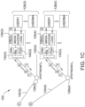
- FIGS. 1A-C are a schematic illustration of an exemplary fiber communication system 100.
- System 100 includes an optical hub 102, a power splitter 104, and a plurality of optical network units (ONUs) 106 in communication with a plurality of customer premises 108, or users, respectively.
- Optical hub 102 is, for example, a central office, a communications hub, and includes an optical line terminal (OLT) 110 for converting standard signals from a service provider (not shown) to the frequency and framing used by the PON system, and for coordinating multiplexing between conversion devices on ONUs 106 respectively located on or near customers premises 108.
- Power splitter 104 may be, for example, a power splitter/combiner.
- OLT 110 contains a hub processor 112 including media access logic, and configured to receive and transmit data to the service provider.
- Processor 112 is in operable communication with at least one downstream transmitter 114 and at least one upstream receiver 116.
- upstream receiver 116 includes a plurality of upstream subreceivers 118, which may be separate components, or separate circuits or portions of a single upstream receiver 116.
- OLT 110 includes one downstream transmitter 114 which may be a 100G coherent transmitter, for four separate upstream subreceivers 118, which may be 25G coherent receivers.
- Downstream transmitter 114 and upstream receiver 116 are in operable communication with a first multiplexer/demultiplexer 120.
- OLT 110 may further include other components (not shown) including, without limitation, a central processing unit (CPU), passive optical network cards, a gateway router (GWR), and voice gateway (VGW) uplink cards.
- CPU central processing unit
- GWR gateway router
- VGW voice gateway
- downstream transmitter 114 and upstream receiver 116 may be included in a single transceiver (not separately shown).
- Exemplary architectures of hub and ONU components are described in greater detail in co-pending U.S. Patent Application Ser. No. 15/283,632, filed October 3, 2016 ,, co-pending U.S. Patent Application Ser. No. 15/590,464, filed May 9, 2017 , and co-pending U.S. Patent Application Ser. No. 15/609,461, filed May 31, 2017 , the disclosures of all of which are incorporated by reference herein.
- ONUs 106 are downstream termination units for the respective customer premises 108.
- a long fiber 122 carries optical signals over a distance from optical hub 102 to power splitter 104.
- long fiber 122 spans a distance of up to 80 kilometers, for a fixed set of wavelengths 1-n.
- power splitter 104 is a 1x4 power splitter, which splits the 100G optical signals from long fiber 122 into the different 25G signals of fixed wavelengths, which are then carried from power splitter 104 by individual short fibers 124 to a plurality of optical splitters 126.
- Each optical splitter further splits the optical signals from an individual short fiber 124 into the different fixed wavelengths, which are then carried between optical splitter 126 and a serving group 128 of respective ONUs 106.
- system 100 includes one optical splitter for each serving group 128, respectively.
- System 100 may be configured, for example, for 1-to-32 or 1-to-64 split ratios (a 1-to-64 split ratio is illustrated in FIGS. 1B-C ) using a fixed set of wavelengths.
- Optical splitters 126 may be, for example, optical splitters/combiners.
- upstream and downstream transmissions are carried over a single long fiber 122.
- long fiber 122 may dedicate separate strands for the upstream and downstream transmissions, respectively.
- system 100 may implement a PON extender such as that illustrated in co-pending U.S. Patent Application Ser. No. 15/609,461 .
- each ONU 116 contains an ONU processor 130 including media access logic, and which configured to receive and transmit data to individual customer premises/users 108.
- Processor 130 is in operable communication with at least one downstream receiver 132 and at least one upstream transmitter 134.
- downstream receivers 132 may be 100G coherent receivers
- upstream transmitters 134 may be 25G coherent transmitters. This asymmetrical coherent reception for downstream and upstream enables enough margin for PON systems. For example, compared to 100G downstream coherent reception, 25G upstream PON has 6-dB higher receiver sensitivity, which translates to 6-dB more link margin for the same transmission distance.
- Downstream receiver 132 and upstream transmitter 134 are in operable communication with a second multiplexer/demultiplexer 136.
- the architecture of system 100 implements 100G coherent PON to enable downstream transmission at fiber distance ranges up to 80 km, while increasing the split ratio to 1:256 without the need of mid-span and pre-amplifiers.
- 100G coherent PON to enable downstream transmission at fiber distance ranges up to 80 km, while increasing the split ratio to 1:256 without the need of mid-span and pre-amplifiers.
- the upstream power budget is reached without the need for a preamplifier.
- TWDMA is implemented with the channel spacing larger than 50GHz to mitigate the impact of backreflections.
- a burst signal structure realizes faster adaption and convergence in an access coherent burst mode receiver, as described below with respect to FIG. 4 .
- exemplary performance is achieved in both the downstream and upstream directions.
- signals are broadcast to all serving groups 128, with each serving group covering 64 users 108, thereby resulting in 256 total end points.
- the signal capacity is 100Gb/s
- the distance reach of system 100 is up to 80 km.
- a cascade tree and/or a start architecture are both enabled.
- exemplary operation is based on a TWDM access mechanism in a coherent burst mode receiver ( FIG. 4 , below).
- TDMA is implemented for each serving group 128, and at 25 Gb/s at each upstream wavelength.
- second multiplexer/demultiplexer 136 includes an optical filter to combine/separate different wavelengths to the various transmitters and receivers.
- multiplexer/demultiplexer may be a diplexer.
- This advantageous architecture still further enables significantly improved versatility for fixed or tunable local oscillators (LOs), as compared with conventional techniques.
- LOs local oscillators
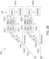
- FIGS. 2A-C are a schematic illustration of a fiber communication system 200.
- System 200 is similar to system 100, except that in the exemplary architecture of system 200, TWDM coherent PON technology is implemented in both the upstream and the downstream directions. Elements that are common to both systems 100 and 200 are labeled with the same reference numerals for ease of explanation.
- the downstream architecture of system 200 may remain substantially the same as the downstream architecture of system 100 (i.e., FIGS. 1B-C , above).
- the upstream architecture of system 200 i.e., FIG. 2A ) though, is modified from system 100. That is, in the exemplary embodiment, system 200 includes an optical hub 202 in operable communication with power splitter 104 along long fiber 122. Similar to optical hub 102, FIG. 1A , optical hub 202 includes an OLT 204 for converting standard signals from the service provider (not shown) to the frequency and framing used by the PON system, and for coordinating multiplexing between conversion devices on ONUs 106.
- OLT 204 contains a hub processor 206 including media access logic, and configured to receive and transmit data to the service provider.
- Processor 206 is in operable communication with at least one downstream transmitting portion 208 and at least one upstream receiving portion 210.
- upstream receiving portion 210 includes a plurality of upstream subreceivers 212, which may be separate components, or separate circuits or portions of a single upstream receiver.
- downstream transmitting portion 208 includes a plurality of subtransmitters 214, which also may be separate components, or separate circuits or portions of a single upstream transmitter.
- each of subtransmitters 214 is a 25G coherent transmitter, and each of upstream subreceivers 212 is a 25G coherent receiver. In some embodiments, one or more of subtransmitters 214 may be paired with a respective subreceiver 212 as an individual subtransceiver.
- Downstream transmitting portion 208 and upstream receiving portion 210 are in operable communication with a first multiplexer/demultiplexer 216, which may also be a diplexer.
- ONUs 106 receive 1-n downstream optical carrier signals from short fibers 124 using standard PON optics.
- Optical splitters 126 also function as nodes of the architecture of system 200.
- ONUs 106 are again illustrated to represent 64 users 108 per serving group 128.
- ONUs 106 may have a symmetric architecture (e.g., 10/10G-EPON), or an asymmetric architecture (e.g., 10/1G-EPON).
- Downstream subtransmitters 214 are each configured to transmit a downstream optical signal ⁇ D(1-n) to multiplexer/demultiplexer 216
- upstream subreceivers 212 are each configured to receive an upstream optical signal ⁇ U(1-n) from multiplexer/demultiplexer 216. That is, the multiplexing function of multiplexer/demultiplexer 216 combines the plurality of downstream optical signals ⁇ D for downstream transmission over long fiber 122, and the demultiplexing function splits the upstream transmission from long fiber 210 into the plurality of respective upstream optical signals ⁇ U .
- the power budget may be calculated as follows: In the downstream direction, a value of fiber loss (including the average connector loss) is assumed to be 0.25 dB/km. Over an 80 km span, the total fiber loss would be approximately 20 dB. The downstream split loss (also in dB) then corresponds to the 1:256 split ratio, for a total expected loss of approximately 25 dB. Given an optical transmitted power with a booster amplifier (not shown) of approximately 10 dBm, and a 100G receiver sensitivity of approximately -40 dBm (at 2x10⁻² with preamplifier), the total power budget (in dB) can be calculated according to 10-(-40)-20-25, or 5 dB.
- the loss budget is improved by group segmentation and wavelength multiplexing for lower data capacity per upstream wavelength. This improvement to the loss budget can be seen by calculating the power budget in the upstream direction as follows.
- the fiber loss in the split loss will be the same as in the downstream direction, i.e., 20 dB and 25 dB, respectively.
- the optical transmitted power without a booster amplifier is approximately ⁇ 0dBm
- in these activities of a 25G receiver sensitivity is approximately -49dBm (at 2x10⁻² with preamplifier).
- the total power budget (in dB) can be calculated according to 0-(-49)-20-25, or 4 dB.
- the additional power budget realized herein is useful to increase the maximum reach of the optical link, and or to increase the split ratio to accommodate more individual end users in the PON.
- the exemplary PON architecture realizes further versatility with respect to the ability to service particular, or increasing quantities of, end users 108.
- both the downstream the upstream transmission are based on four wavelengths, thereby enabling more targeted transmissions downstream optical signals into individual serving groups 128, but while still maintaining fiber transmission distances of up to 80 km utilizing passive technologies (e.g., without the need for pre-amplification or mid-span).
- this bi-directional TWDM technique allows for still further modifications and innovations to enable targeted transmissions to single ONUs 106, which is particularly advantageous in the case where a single ONU represents a high-volume business user, for example.
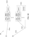
- individual serving groups 128 of system 300 may serve a variable quantity of ONUs 106. That is, where serving groups 128(1) and 128(4) are substantially the same in systems 100, 200, and 300, serving groups 128(2)' and 128(3)' are different from serving groups 128(2) and 128(3), FIGS. 1B , 2B , in that serving groups 128(2)' and 128(3)' each represent a single ONU 106 and a single user 108 (i.e., users 108(2)' and 108(3)', respectively).
- short fibers 124 may directly connect power splitter 104 to individual ONUs 106 (e.g., ONUs 106(2) and 106(3), respectively).
- the passive technology techniques described above can be maintained over similar lengths of fiber deployment (e.g., 80 km), but for fewer individual end users 108 (130 in this example, as compared with 256 in the examples described above).
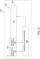
- FIG. 4 is a schematic illustration of an exemplary burst signal format 400 for a coherent burst mode receiver 402.
- Burst mode receiver 402 may be implemented, for example, with any or all of systems 100, 200, 300, described above.
- Burst signal format 400 is configured to process a data stream 404 against a demodulation process 406.
- Data stream 404 includes at least one header 408 and at least one payload 410.
- header 408 is configured to include a first portion 412 having single polarization (single-pol) signals, and a second portion having a training sequence 414.
- burst mode receiver 402 the single-pol signals of first portion 412 and the training sequence of second portion 414 are subjected to demodulation process 406 reliability of payload 410.
- demodulation process 406 (i) enables independent detection of static information without the need for polarization demultiplexing (thereby advantageously lowering the data rate), and (ii) provides a dynamic channel information.
- the static and dynamic information may both be more effectively utilized in demodulation process 406 for payload 410 to realize a significantly faster convergence speed.
- burst-mode coherent detection should therefore be realized when multiple optical network units (ONUs) send signals back to the same optical line terminal (OLT).
- OLT optical line terminal
- the ONU only transmits an upstream optical packet when the ONU is allocated a time slot for the transmission (and the ONU needs to transmit).
- All of the multiple ONUs share the upstream channel in the time division multiple access (TDMA) mode, but all of the respective upstream signals therefrom will have different power levels, different wavelength drifting, and different lengths of signal durations.
- TDMA time division multiple access
- Conventional techniques have had significant difficulty in completing receiver equalization within the time of a 100-Gb/s burst overhead. The techniques described and illustrated with respect to FIG.
- An optical network communication system utilizing a passive optical network comprising: an optical hub including an optical line terminal having a downstream transmitter, an upstream receiver, a processor, and a multiplexer, wherein the upstream receiver includes a plurality of upstream subreceivers configured for time-wavelength division multiplexing access (TWDMA); a power splitter configured to divide a coherent optical signal from the optical hub into a plurality of downstream wavelength signals; a long fiber configured to carry the coherent optical signal between the optical hub and the power splitter; a plurality of serving groups, each of the plurality of serving groups including a plurality of optical network units configured to (i) receive at least one of the plurality of downstream wavelength signals, and (ii) transmit at least one upstream wavelength signal; and a plurality of short fibers configured to carry the downstream and upstream wavelength signals between the power splitter and the plurality of optical network units, respectively, wherein each of the plurality of upstream subreceivers is configured to receive a respective upstream wavelength signal
- TWDMA time-wave
- a(ii) The system of claim a(i), wherein the plurality of short fibers comprises four short fibers, and wherein the power splitter is configured to implement a 1x4 split from the long fiber to the four short fibers.
- optical splitter configured to implement a 1x64 split from the at least one of the four short fibers to a respecting serving group of 64 optical network units.
- downstream transmitter comprises a plurality of downstream subtransmitters.
- each of the plurality of downstream subtransmitters is configured to transmit at least one of the plurality of downstream wavelength signals to a particular one of the plurality of serving groups.
- each of the plurality of downstream subtransmitters is configured for TWDMA.
- TWDMA is implemented with a channel spacing greater than 50 GHz.
- each of the upstream subreceivers comprises a 25G coherent receiver.
- processor comprises media access logic
- each of the optical network units comprises an upstream transmitter and a downstream receiver, wherein the upstream transmitter is configured to transmit the at least one upstream wavelength signal, and wherein the downstream receiver is configured to receive at least one of the downstream wavelength signals from the optical hub.
- a(xv) The system of claim a(xiv), wherein the downstream receiver comprises a 100G coherent receiver.
- a(xviii) The system of claim a(i), wherein a length of the PON spans a distance of 80 km from the optical hub to at least one of the plurality of optical network units.
- a(xix) The system of claim a(i), wherein the PON comprises at least one of a cascade tree topology and a start architecture topology.
- a burst signal format data structure in a coherent burst mode receiver comprising: a data stream configured to include a data header and a data payload, wherein the data header includes at least one single-polarization signal and at least one training sequence; and a demodulation process configured to detect static information from the data header and provide dynamic channel information to the data payload.
- Some embodiments involve the use of one or more electronic or computing devices.
- Such devices typically include a processor or controller, such as a general purpose central processing unit (CPU), a graphics processing unit (GPU), a microcontroller, a reduced instruction set computer (RISC) processor, an application specific integrated circuit (ASIC), a programmable logic circuit (PLC), a field programmable gate array (FPGA), a digital signal processing (DSP) device, and/or any other circuit or processor capable of executing the functions described herein.
- the processes described herein may be encoded as executable instructions embodied in a computer readable medium, including, without limitation, a storage device and/or a memory device. Such instructions, when executed by a processor, cause the processor to perform at least a portion of the methods described herein.
- the above examples are exemplary only, and thus are not intended to limit in any way the definition and/or meaning of the term "processor.”
Landscapes
- Engineering & Computer Science (AREA)
- Computer Networks & Wireless Communication (AREA)
- Signal Processing (AREA)
- Physics & Mathematics (AREA)
- Electromagnetism (AREA)
- Optical Communication System (AREA)
- Small-Scale Networks (AREA)
Applications Claiming Priority (4)
| Application Number | Priority Date | Filing Date | Title |
|---|---|---|---|
| US201762476403P | 2017-03-24 | 2017-03-24 | |
| EP18717198.8A EP3602855A1 (fr) | 2017-03-24 | 2018-03-23 | Système et procédés pour une architecture pon cohérente et une réception en mode rafale |
| EP21199268.0A EP3952152A1 (fr) | 2017-03-24 | 2018-03-23 | Système et procédés pour architecture pon cohérente et réception en mode rafale |
| PCT/US2018/024117 WO2018175946A1 (fr) | 2017-03-24 | 2018-03-23 | Système et procédés pour une architecture pon cohérente et une réception en mode rafale |
Related Parent Applications (2)
| Application Number | Title | Priority Date | Filing Date |
|---|---|---|---|
| EP21199268.0A Division EP3952152A1 (fr) | 2017-03-24 | 2018-03-23 | Système et procédés pour architecture pon cohérente et réception en mode rafale |
| EP18717198.8A Division EP3602855A1 (fr) | 2017-03-24 | 2018-03-23 | Système et procédés pour une architecture pon cohérente et une réception en mode rafale |
Publications (2)
| Publication Number | Publication Date |
|---|---|
| EP4525331A2 true EP4525331A2 (fr) | 2025-03-19 |
| EP4525331A3 EP4525331A3 (fr) | 2025-06-18 |
Family
ID=61953010
Family Applications (3)
| Application Number | Title | Priority Date | Filing Date |
|---|---|---|---|
| EP25155262.6A Pending EP4525331A3 (fr) | 2017-03-24 | 2018-03-23 | Système et procédés pour architecture pon cohérente et réception en mode rafale |
| EP21199268.0A Withdrawn EP3952152A1 (fr) | 2017-03-24 | 2018-03-23 | Système et procédés pour architecture pon cohérente et réception en mode rafale |
| EP18717198.8A Pending EP3602855A1 (fr) | 2017-03-24 | 2018-03-23 | Système et procédés pour une architecture pon cohérente et une réception en mode rafale |
Family Applications After (2)
| Application Number | Title | Priority Date | Filing Date |
|---|---|---|---|
| EP21199268.0A Withdrawn EP3952152A1 (fr) | 2017-03-24 | 2018-03-23 | Système et procédés pour architecture pon cohérente et réception en mode rafale |
| EP18717198.8A Pending EP3602855A1 (fr) | 2017-03-24 | 2018-03-23 | Système et procédés pour une architecture pon cohérente et une réception en mode rafale |
Country Status (4)
| Country | Link |
|---|---|
| US (4) | US10484124B2 (fr) |
| EP (3) | EP4525331A3 (fr) |
| CA (1) | CA3057833C (fr) |
| WO (1) | WO2018175946A1 (fr) |
Families Citing this family (8)
| Publication number | Priority date | Publication date | Assignee | Title |
|---|---|---|---|---|
| CA3057833C (fr) * | 2017-03-24 | 2020-04-21 | Cable Television Laboratories, Inc. | Systeme et procedes pour une architecture pon coherente et une reception en mode rafale |
| WO2019020170A1 (fr) * | 2017-07-25 | 2019-01-31 | Telefonaktiebolaget Lm Ericsson (Publ) | Procédés, appareil et supports lisibles par ordinateur pour synchronisation sur un réseau optique |
| US11039229B2 (en) * | 2017-08-29 | 2021-06-15 | Cable Television Laboratories, Inc. | Systems and methods for coherent optics ranging and sensing |
| CN110634165B (zh) * | 2019-03-25 | 2021-10-29 | 清华大学深圳研究生院 | 一种基于rgb三通道信息融合的光场图像去散射方法 |
| CN113573175B (zh) * | 2020-04-29 | 2023-03-24 | 中国电信股份有限公司 | 光线路终端及其业务处理方法 |
| CN111901047A (zh) * | 2020-06-19 | 2020-11-06 | 烽火通信科技股份有限公司 | 一种高速突发信号的快速均衡方法与装置 |
| CN112312239B (zh) * | 2020-10-22 | 2022-08-02 | 武汉邮电科学研究院有限公司 | 用于相干pon中上行突发模式的前导码设计方法及系统 |
| US12074646B1 (en) * | 2021-08-26 | 2024-08-27 | Cable Television Laboratories, Inc. | Systems and methods for coherent burst reception |
Family Cites Families (69)
| Publication number | Priority date | Publication date | Assignee | Title |
|---|---|---|---|---|
| US5067139A (en) * | 1990-12-17 | 1991-11-19 | Motorola, Inc. | Coherent detector for QPSK modulation in a TDMA system |
| EP0684708B1 (fr) * | 1993-12-15 | 2005-10-26 | Ntt Mobile Communications Network Inc. | Egaliseur a adaptation automatique |
| WO1999003296A1 (fr) * | 1997-07-14 | 1999-01-21 | Hughes Electronics Corporation | Attribution immediate de canaux dans un systeme sans fil |
| US7076168B1 (en) * | 1998-02-12 | 2006-07-11 | Aquity, Llc | Method and apparatus for using multicarrier interferometry to enhance optical fiber communications |
| US7139340B2 (en) * | 2002-06-28 | 2006-11-21 | Hitachi, Ltd. | Robust OFDM carrier recovery methods and apparatus |
| SG129231A1 (en) * | 2002-07-03 | 2007-02-26 | Oki Techno Ct Singapore Pte | Receiver and method for wlan burst type signals |
| SG104340A1 (en) * | 2002-07-03 | 2004-06-21 | Oki Techno Ct Singapore Pte | Receiver and method for wlan burst type signals |
| EP1465354A1 (fr) * | 2003-04-01 | 2004-10-06 | STMicroelectronics N.V. | Procédé et dispositif de synchronisation dans un système de communication de données sans fil à bande ultra large |
| US7260055B2 (en) * | 2003-05-30 | 2007-08-21 | Agency For Science, Technology, And Research | Method for reducing channel estimation error in an OFDM system |
| US8958697B2 (en) * | 2003-06-10 | 2015-02-17 | Alexander I. Soto | System and method for optical layer management in optical modules and remote control of optical modules |
| US7242868B2 (en) * | 2003-06-10 | 2007-07-10 | Soto Alexander I | System and method for performing high-speed communications over fiber optical networks |
| US7315575B2 (en) * | 2004-03-08 | 2008-01-01 | Nortel Networks Limited | Equalization strategy for dual-polarization optical transport system |
| EP1924043B1 (fr) * | 2005-09-06 | 2014-06-18 | Nippon Telegraph And Telephone Corporation | Appareil d émission radio, appareil de réception radio, méthode d émission radio, méthode de réception radio, système de communication sans fil et méthode de communication sans fil |
| US7555227B2 (en) * | 2005-10-21 | 2009-06-30 | Nortel Networks Limited | Polarization compensation in a coherent optical receiver |
| US7522841B2 (en) * | 2005-10-21 | 2009-04-21 | Nortel Networks Limited | Efficient data transmission and training of data processing functions |
| US7991296B1 (en) * | 2006-11-10 | 2011-08-02 | Marvell International Ltd. | Method and apparatus for data frame synchronization and delineation |
| US7983308B1 (en) * | 2006-11-28 | 2011-07-19 | Marvell International Ltd. | Method and apparatus for data frame synchronization |
| US8213795B2 (en) * | 2007-05-09 | 2012-07-03 | University Of Central Florida Research Foundation, Inc. | Systems and methods of polarization time coding for optical communications |
| TWI366350B (en) * | 2007-09-05 | 2012-06-11 | Ite Tech Inc | Apparatus for channel estimation |
| ES2431337T3 (es) * | 2008-06-04 | 2013-11-26 | Sony Corporation | Nueva estructura de trama para sistemas de múltiples portadoras |
| CN102113256B (zh) * | 2008-07-31 | 2015-06-17 | 骁阳网络有限公司 | 用于在光网络中处理数据的方法、光网络组件和通信系统 |
| US8203929B2 (en) * | 2008-10-09 | 2012-06-19 | Sony Corporation | Frame and data pattern structure for multi-carrier systems |
| US8233809B2 (en) * | 2008-10-28 | 2012-07-31 | Nec Laboratories America, Inc. | Polarization independent frequency domain equalization (FDE) for chromatic dispersion (CD) compensation in PolMux coherent systems |
| US8238406B2 (en) * | 2009-03-25 | 2012-08-07 | Texas Instruments Incorporated | Time-hopping sequence for burst mode communications |
| CN102439873B (zh) * | 2009-07-17 | 2015-03-11 | 华为技术有限公司 | 恢复OTUk帧的方法、装置及传送OTUk帧的系统 |
| US8340534B2 (en) * | 2009-08-07 | 2012-12-25 | Futurewei Technologies, Inc. | Side band pilot tone for digital signal processing in polarization multiplexed coherent optical communication system |
| US8315528B2 (en) * | 2009-12-22 | 2012-11-20 | Ciena Corporation | Zero mean carrier recovery |
| US8391726B2 (en) * | 2010-02-25 | 2013-03-05 | Futurewei Technologies, Inc. | Method and apparatus for frame detection and polarization separation |
| US9036999B2 (en) * | 2010-07-31 | 2015-05-19 | Alcatel Lucent | Frame/symbol synchronization in coherent optical OFDM |
| EP2568636B1 (fr) * | 2011-09-06 | 2013-11-13 | Alcatel Lucent | Système optique à mode rafale PDM-QAM avec symboles de synchronisation OFDM |
| US8320760B1 (en) | 2011-11-03 | 2012-11-27 | Google Inc. | Passive optical network with asymmetric modulation scheme |
| CN104541518B (zh) * | 2012-06-05 | 2018-10-09 | 华为技术有限公司 | 一种构建以太网无源光网络的同轴汇聚层的方法和装置 |
| CN103516434B (zh) * | 2012-06-19 | 2016-08-31 | 上海贝尔股份有限公司 | 光发射机 |
| CN102884735B (zh) * | 2012-06-29 | 2015-07-08 | 华为技术有限公司 | 光突发信号接收方法、装置和一种光突发信号接收机 |
| US20140031441A1 (en) | 2012-07-30 | 2014-01-30 | Sabic Innovative Plastics Ip B.V. | Process for the Preparation of Modified Poly(Alkylene Terephthalate) Employing an In-Situ Titanium-Containing Catalyst |
| CN103973389B (zh) * | 2013-02-06 | 2017-05-24 | 上海贝尔股份有限公司 | 一种用于自动配置光网络单元的波长的方法 |
| US9225453B2 (en) * | 2013-04-09 | 2015-12-29 | Futurewei Technologies, Inc. | Optimizing optical systems using code division multiple access and/or orthogonal frequency-division multiplexing |
| US9425918B2 (en) * | 2013-04-19 | 2016-08-23 | Futurewei Technologies, Inc. | Flexible TWDM PON with load balancing and power saving |
| CN105164941B (zh) * | 2013-05-06 | 2017-11-24 | 华为技术有限公司 | 光信道探测器 |
| EP2989737B1 (fr) * | 2013-05-16 | 2018-01-03 | Huawei Technologies Co., Ltd. | Architectures de réseau d'accès optique reconfigurables |
| CN105379158B (zh) * | 2013-05-16 | 2018-11-16 | 华为技术有限公司 | 时分和波分复用无源光网络的方法和光线路终端 |
| EP2999184B1 (fr) * | 2013-06-08 | 2018-03-21 | Huawei Technologies Co., Ltd. | Procédé, dispositif et système de réception et d'émission de données |
| US20150055956A1 (en) * | 2013-08-26 | 2015-02-26 | Electronics And Telecommunications Research Institute | Passive optical network system using time division multiplexing |
| JP5805725B2 (ja) * | 2013-10-04 | 2015-11-04 | ザインエレクトロニクス株式会社 | 送信装置、受信装置、送受信システムおよび画像表示システム |
| JP6034273B2 (ja) * | 2013-10-04 | 2016-11-30 | ザインエレクトロニクス株式会社 | 送信装置、受信装置、送受信システムおよび画像表示システム |
| JP6227974B2 (ja) * | 2013-10-29 | 2017-11-08 | 日本電信電話株式会社 | バースト信号受信方法 |
| EP3082276A4 (fr) * | 2013-12-10 | 2017-11-08 | Mitsubishi Electric Corporation | Système de transport multiplexé par longueur d'onde |
| CN104901906B (zh) * | 2014-03-07 | 2019-11-05 | 中兴通讯股份有限公司 | 一种相干光通信信道估计方法和系统 |
| US9906299B2 (en) * | 2014-03-08 | 2018-02-27 | Avago Technologies General Ip (Singapore) Pte. Ltd. | Upstream frame configuration for ethernet passive optical network protocol over coax (EPoC) networks |
| JP6114464B2 (ja) * | 2014-03-20 | 2017-04-12 | 日本電信電話株式会社 | 伝送装置及び伝送方法 |
| US9832094B2 (en) * | 2014-03-24 | 2017-11-28 | Qualcomm Incorporated | Multi-wire electrical parameter measurements via test patterns |
| CN105580300A (zh) | 2014-05-12 | 2016-05-11 | 华为技术有限公司 | 一种波长切换的方法、装置及系统 |
| CN104010233B (zh) * | 2014-05-15 | 2018-02-09 | 北京大学 | 一种基于rsoa的偏振复用相干检测无源光网络 |
| US9391712B2 (en) * | 2014-06-16 | 2016-07-12 | Futurewei Technologies, Inc. | Upstream optical transmission assignment based on transmission power |
| US20160262138A1 (en) * | 2014-06-17 | 2016-09-08 | Telefonaktiebolaget L M Ericsson (Publ) | Methods and Apparatuses for Repeated Radio Block Transmission |
| EP2996264A1 (fr) * | 2014-09-12 | 2016-03-16 | Xieon Networks S.à r.l. | Estimation de dispersion chromatique assistée par des données |
| US9780906B2 (en) * | 2014-10-07 | 2017-10-03 | Futurewei Technologies, Inc. | Multiple-wavelength passive optical network (PON) power saving |
| CN107113258B (zh) * | 2014-11-13 | 2020-10-09 | 瑞典爱立信有限公司 | 相干光学接收器中光学通信信号的数字信号处理 |
| US10264525B2 (en) * | 2014-11-17 | 2019-04-16 | University Of Notre Dame Du Lac | Energy efficient communications |
| KR102286577B1 (ko) | 2015-04-03 | 2021-08-06 | 한국전자통신연구원 | 광통신 네트워크에서 다수의 서브 채널들을 이용한 광네트워크유닛의 등록/등록해제 장치 및 방법 |
| US10110317B1 (en) * | 2015-09-04 | 2018-10-23 | Inphi Corporation | Apparatus and methods for transmitter skew and bias error compensation in an optical communication system |
| US9806814B2 (en) * | 2015-11-24 | 2017-10-31 | Futurewei Tecnologies, Inc. | Joint acquisition of chromatic dispersion and frequency offset in optical systems |
| KR101906149B1 (ko) * | 2015-12-30 | 2018-10-10 | 어보브반도체 주식회사 | 개선된 심볼 타이밍 오프셋 보상을 사용하는 블루투스 수신 방법 및 장치 |
| US10305621B2 (en) * | 2016-07-26 | 2019-05-28 | Futurewei Technologies, Inc. | Burst-mode discrete multi-tone for networks |
| JP2018082336A (ja) * | 2016-11-17 | 2018-05-24 | 富士通株式会社 | 光伝送装置、及び、光伝送方法 |
| CA3057833C (fr) * | 2017-03-24 | 2020-04-21 | Cable Television Laboratories, Inc. | Systeme et procedes pour une architecture pon coherente et une reception en mode rafale |
| GB2569288A (en) * | 2017-12-07 | 2019-06-19 | Purelifi Ltd | Low power receiver apparatus |
| WO2019191730A1 (fr) * | 2018-03-29 | 2019-10-03 | Cable Television Laboratories, Inc. | Systèmes et procédés associés à une optique cohérente dans un réseau d'accès |
| KR102542679B1 (ko) * | 2019-02-20 | 2023-06-13 | 후아웨이 테크놀러지 컴퍼니 리미티드 | 광 신호용 디지털 신호 처리(odsp)와 관련된 수동 광 네트워크(pons)의 통신 |
-
2018
- 2018-03-23 CA CA3057833A patent/CA3057833C/fr active Active
- 2018-03-23 US US15/934,321 patent/US10484124B2/en active Active
- 2018-03-23 WO PCT/US2018/024117 patent/WO2018175946A1/fr not_active Ceased
- 2018-03-23 EP EP25155262.6A patent/EP4525331A3/fr active Pending
- 2018-03-23 EP EP21199268.0A patent/EP3952152A1/fr not_active Withdrawn
- 2018-03-23 EP EP18717198.8A patent/EP3602855A1/fr active Pending
-
2019
- 2019-10-18 US US16/657,781 patent/US10958371B2/en active Active
-
2021
- 2021-03-22 US US17/208,697 patent/US11362756B2/en active Active
-
2022
- 2022-06-13 US US17/838,853 patent/US11949497B2/en active Active
Also Published As
| Publication number | Publication date |
|---|---|
| EP3952152A1 (fr) | 2022-02-09 |
| US20220321245A1 (en) | 2022-10-06 |
| WO2018175946A1 (fr) | 2018-09-27 |
| CA3057833A1 (fr) | 2018-09-27 |
| EP4525331A3 (fr) | 2025-06-18 |
| US20180278360A1 (en) | 2018-09-27 |
| US10484124B2 (en) | 2019-11-19 |
| US11949497B2 (en) | 2024-04-02 |
| EP3602855A1 (fr) | 2020-02-05 |
| US11362756B2 (en) | 2022-06-14 |
| US20200052808A1 (en) | 2020-02-13 |
| CA3057833C (fr) | 2020-04-21 |
| US10958371B2 (en) | 2021-03-23 |
| US20210226718A1 (en) | 2021-07-22 |
Similar Documents
| Publication | Publication Date | Title |
|---|---|---|
| US11949497B2 (en) | System and methods for coherent PON architecture and burst-mode reception | |
| Liu | Enabling optical network technologies for 5G and beyond | |
| Zhang et al. | Coherent passive optical networks for 100G/λ-and-beyond fiber access: recent progress and outlook | |
| Song et al. | Long-reach optical access networks: A survey of research challenges, demonstrations, and bandwidth assignment mechanisms | |
| CN101399617B (zh) | 局端光通信装置及光通信系统 | |
| US12149339B1 (en) | System and methods for coherent optical extension | |
| US8953942B1 (en) | Hybrid WDM-TDM passive optical network | |
| Obite et al. | The evolution of ethernet passive optical network (EPON) and future trends | |
| CN102035789A (zh) | 基于光正交频分复用动态分配的无源接入网系统和方法 | |
| Pagare et al. | Design and analysis of hybrid optical distribution network for worst-case scenario of E2-class symmetric coexistence 80 Gbps TWDM NG-PON2 architecture for FTTX access networks | |
| Kumari et al. | Passive optical network evolution to next generation passive optical network: A review | |
| Nesset | Next generation PON technologies: 50G PON and beyond | |
| Liu et al. | Emerging optical communication technologies for 5G | |
| Ghoniemy | Enhanced time and wavelength division multiplexed passive optical network (TWDM-PON) for triple-play broadband service delivery in FTTx networks | |
| CN103313150A (zh) | 基于直调激光器的混合波分时分复用无源光网络传输系统 | |
| US9699532B2 (en) | Systems and methods of hybrid DWDM aggregation and extension for time division multiplexing passive optical networks | |
| CN102104814B (zh) | 一种无源光网络 | |
| KR20170001051A (ko) | 시분할다중화 및 파장분할다중화 방식을 적용한 차세대 수동 광 네트워크 종단 장치 | |
| Gupta et al. | A simple one-system solution COF-PON for metro/access networks | |
| Rajalakshmi et al. | Analysis of TDM and WDM PON using different coding schemes for extended reach | |
| Huang et al. | A novel flexible optical remote node architecture for dynamic wavelength allocation over hybrid WDM/TDM PON systems | |
| SHANAN | DESIGN OF RADIO OVER FIBER SYSTEM FOR WIRELESS ACCESS | |
| Jiang | Progress and challenges for high speed optical access networks | |
| Song et al. | Long-reach optical access | |
| CN104009791A (zh) | 基于无源光网络间资源共享的交叉保护系统 |
Legal Events
| Date | Code | Title | Description |
|---|---|---|---|
| PUAI | Public reference made under article 153(3) epc to a published international application that has entered the european phase |
Free format text: ORIGINAL CODE: 0009012 |
|
| STAA | Information on the status of an ep patent application or granted ep patent |
Free format text: STATUS: THE APPLICATION HAS BEEN PUBLISHED |
|
| AC | Divisional application: reference to earlier application |
Ref document number: 3602855 Country of ref document: EP Kind code of ref document: P Ref document number: 3952152 Country of ref document: EP Kind code of ref document: P |
|
| AK | Designated contracting states |
Kind code of ref document: A2 Designated state(s): AL AT BE BG CH CY CZ DE DK EE ES FI FR GB GR HR HU IE IS IT LI LT LU LV MC MK MT NL NO PL PT RO RS SE SI SK SM TR |
|
| REG | Reference to a national code |
Ref country code: DE Ref legal event code: R079 Free format text: PREVIOUS MAIN CLASS: H04B0010610000 Ipc: H04J0014020000 |
|
| PUAL | Search report despatched |
Free format text: ORIGINAL CODE: 0009013 |
|
| AK | Designated contracting states |
Kind code of ref document: A3 Designated state(s): AL AT BE BG CH CY CZ DE DK EE ES FI FR GB GR HR HU IE IS IT LI LT LU LV MC MK MT NL NO PL PT RO RS SE SI SK SM TR |
|
| RIC1 | Information provided on ipc code assigned before grant |
Ipc: H04B 10/61 20130101ALI20250513BHEP Ipc: H04J 14/02 20060101AFI20250513BHEP |
|
| STAA | Information on the status of an ep patent application or granted ep patent |
Free format text: STATUS: REQUEST FOR EXAMINATION WAS MADE |
|
| 17P | Request for examination filed |
Effective date: 20251211 |