EP4525222A1 - Flat cable assembly and rotational connector device - Google Patents
Flat cable assembly and rotational connector device Download PDFInfo
- Publication number
- EP4525222A1 EP4525222A1 EP23811734.5A EP23811734A EP4525222A1 EP 4525222 A1 EP4525222 A1 EP 4525222A1 EP 23811734 A EP23811734 A EP 23811734A EP 4525222 A1 EP4525222 A1 EP 4525222A1
- Authority
- EP
- European Patent Office
- Prior art keywords
- conductor
- flat cable
- cable
- cable connector
- connector assembly
- Prior art date
- Legal status (The legal status is an assumption and is not a legal conclusion. Google has not performed a legal analysis and makes no representation as to the accuracy of the status listed.)
- Pending
Links
Images







Classifications
-
- H—ELECTRICITY
- H01—ELECTRIC ELEMENTS
- H01R—ELECTRICALLY-CONDUCTIVE CONNECTIONS; STRUCTURAL ASSOCIATIONS OF A PLURALITY OF MUTUALLY-INSULATED ELECTRICAL CONNECTING ELEMENTS; COUPLING DEVICES; CURRENT COLLECTORS
- H01R12/00—Structural associations of a plurality of mutually-insulated electrical connecting elements, specially adapted for printed circuits, e.g. printed circuit boards [PCB], flat or ribbon cables, or like generally planar structures, e.g. terminal strips, terminal blocks; Coupling devices specially adapted for printed circuits, flat or ribbon cables, or like generally planar structures; Terminals specially adapted for contact with, or insertion into, printed circuits, flat or ribbon cables, or like generally planar structures
- H01R12/50—Fixed connections
- H01R12/59—Fixed connections for flexible printed circuits, flat or ribbon cables or like structures
- H01R12/592—Fixed connections for flexible printed circuits, flat or ribbon cables or like structures connections to contact elements
-
- B—PERFORMING OPERATIONS; TRANSPORTING
- B60—VEHICLES IN GENERAL
- B60R—VEHICLES, VEHICLE FITTINGS, OR VEHICLE PARTS, NOT OTHERWISE PROVIDED FOR
- B60R16/00—Electric or fluid circuits specially adapted for vehicles and not otherwise provided for; Arrangement of elements of electric or fluid circuits specially adapted for vehicles and not otherwise provided for
- B60R16/02—Electric or fluid circuits specially adapted for vehicles and not otherwise provided for; Arrangement of elements of electric or fluid circuits specially adapted for vehicles and not otherwise provided for electric constitutive elements
- B60R16/023—Electric or fluid circuits specially adapted for vehicles and not otherwise provided for; Arrangement of elements of electric or fluid circuits specially adapted for vehicles and not otherwise provided for electric constitutive elements for transmission of signals between vehicle parts or subsystems
- B60R16/027—Electric or fluid circuits specially adapted for vehicles and not otherwise provided for; Arrangement of elements of electric or fluid circuits specially adapted for vehicles and not otherwise provided for electric constitutive elements for transmission of signals between vehicle parts or subsystems between relatively movable parts of the vehicle, e.g. between steering wheel and column
-
- H—ELECTRICITY
- H01—ELECTRIC ELEMENTS
- H01R—ELECTRICALLY-CONDUCTIVE CONNECTIONS; STRUCTURAL ASSOCIATIONS OF A PLURALITY OF MUTUALLY-INSULATED ELECTRICAL CONNECTING ELEMENTS; COUPLING DEVICES; CURRENT COLLECTORS
- H01R35/00—Flexible or turnable line connectors, i.e. the rotation angle being limited
- H01R35/02—Flexible line connectors without frictional contact members
- H01R35/025—Flexible line connectors without frictional contact members having a flexible conductor wound around a rotation axis
-
- H—ELECTRICITY
- H01—ELECTRIC ELEMENTS
- H01R—ELECTRICALLY-CONDUCTIVE CONNECTIONS; STRUCTURAL ASSOCIATIONS OF A PLURALITY OF MUTUALLY-INSULATED ELECTRICAL CONNECTING ELEMENTS; COUPLING DEVICES; CURRENT COLLECTORS
- H01R4/00—Electrically-conductive connections between two or more conductive members in direct contact, i.e. touching one another; Means for effecting or maintaining such contact; Electrically-conductive connections having two or more spaced connecting locations for conductors and using contact members penetrating insulation
- H01R4/02—Soldered or welded connections
- H01R4/023—Soldered or welded connections between cables or wires and terminals
-
- H—ELECTRICITY
- H01—ELECTRIC ELEMENTS
- H01R—ELECTRICALLY-CONDUCTIVE CONNECTIONS; STRUCTURAL ASSOCIATIONS OF A PLURALITY OF MUTUALLY-INSULATED ELECTRICAL CONNECTING ELEMENTS; COUPLING DEVICES; CURRENT COLLECTORS
- H01R4/00—Electrically-conductive connections between two or more conductive members in direct contact, i.e. touching one another; Means for effecting or maintaining such contact; Electrically-conductive connections having two or more spaced connecting locations for conductors and using contact members penetrating insulation
- H01R4/02—Soldered or welded connections
- H01R4/027—Soldered or welded connections comprising means for positioning or holding the parts to be soldered or welded
Definitions
- the restriction portion protrudes from the first surface of the connector body in the first direction.
- the restriction portion protrudes from the first surface of the connector body in the first direction, the structure of the restriction portion can be relatively simple. Accordingly, it is possible to suppress or prevent short-circuiting between the first flat cable and second flat cable while reliably suppressing the increase in the manufacturing cost.
- the first flat cable has a first thickness defined in the first direction in a state where the first conductor connection portion is electrically connected to the first bus bar.
- the second flat cable has a second thickness defined in the first direction in a state where the second conductor connection portion is electrically connected to the second bus bar.
- the restriction portion has a protrusion length defined in the first direction from the first surface. The protrusion length is greater than the second thickness.
- the protruding length is greater than the total of the first thickness and the second thickness, the distance between the first conductor exposed portion and the second conductor exposed portion in the first direction can be secured more effectively. Accordingly, it is possible to reliably suppress or prevent short-circuiting between the first flat cable and the second flat cable while reliably suppressing the increase in the manufacturing cost.
- the restriction portion is integrally provided with the connector body.
- the first conductor exposed portion is disposed to at least partially overlap the second conductor exposed portion when viewed from the first direction.
- the space occupied by the first flat cable and the first flat cable can be reduced, thereby enabling miniaturization of the cable connector assembly.
- the first flat cable includes a main body portion including the first conductor connection portion and an overlapping portion at least partially including the first conductor exposed portion and disposed to overlap at least partially the second conductor exposed portion when viewed from the first direction.
- the restriction portion is contactable with the overlapping portion to restrict the overlapping portion from moving toward the second conductor exposed portion in the first direction.
- the restriction portion includes a contact surface contactable with the overlapping portion.
- the contact surface includes an inclined surface inclined relative to the first direction.
- the cable connector assembly according to the ninth aspect by providing the inclined surface to the restriction portion, an increase in a space occupied by the restriction portion can be suppressed. Accordingly, it is possible to suppress or prevent short-circuiting between the first flat cable and the second flat cable while reliably suppressing the increase in the manufacturing cost.
- the overlapping portion is inclined relative to the main body portion in a state where the restriction portion restricts the first conductor exposed portion from moving toward the second conductor exposed portion.
- the overlapping portion is inclined relative to the main body portion, the increase in the space occupied by the overlapping portion can be suppressed. Accordingly, it is possible to suppress or prevent short-circuiting between the first flat cable and the second flat cable while reliably suppressing the increase in the manufacturing cost.
- the overlapping portion protrudes from the main body portion when viewed from the first direction in a state where the restriction portion restricts the first conductor exposed portion from moving toward the second conductor exposed portion.
- the cable connector assembly according to the eleventh aspect since it is not necessary to pre-bend the overlapping portion, the work of attaching the first flat cable to the cable connector becomes relatively easy. Accordingly, it is possible to suppress or prevent short-circuiting between the first flat cable and the second flat cable while reliably suppressing the increase in the manufacturing cost.
- the restriction portion includes a support groove contactable with the overlapping portion to restrict the first conductor exposed portion from moving toward the second conductor exposed portion in the first direction.
- the overlapping portion is at least partially disposed in the support groove.
- the support groove can support the overlapping portion by utilizing the elastic force of the overlapping portion, the restriction portion can be realized with a relatively simple structure. Accordingly, it is possible to suppress or prevent short-circuiting between the first flat cable and the second flat cable while reliably suppressing the increase in the manufacturing cost.
- the overlapping portion is disposed to at least partially overlap the main body portion when viewed from the first direction in a state where the overlapping portion is disposed in the support groove.
- the cable connector assembly according to the fourteenth aspect it is possible to suppress the increase in the space occupied by the overlapping portion. Accordingly, it is possible to suppress or prevent short-circuiting between the first flat cable and the second flat cable while reliably suppressing the increase in the manufacturing cost.
- the cable connector assembly further comprises a holding portion provided in the restriction portion.
- the holding portion is contactable with the first flat cable to restrict the first conductor exposed portion from moving away from the second conductor exposed portion in the first direction.
- the holding portion makes the position of the first conductor exposed portion relative to the second conductor exposed portion more stable.
- the holding portion protrudes from the restriction portion in the first direction.
- the holding portion can be realized with a simple structure.
- the first flat cable includes a holding opening.
- the holding portion protrudes from the restriction portion through the holding opening in the first direction.
- the holding portion can be realized with a simpler structure.
- a rotary connector device includes a stator, a rotator rotatable about a rotational axis relative to the stator, and the cable connector assembly according to any one of the first to fifth aspects.
- the rotary connector device With the rotary connector device according to the eighteenth aspect, by using the cable connector assembly, it is possible to suppress or prevent short-circuiting between the first flat cable and the second flat cable while suppressing the increase in the manufacturing cost of the rotary connector device.
- the cable connector assembly that can suppress or prevent short-circuiting between the first flat cable and the second flat cable while suppressing the increase in the manufacturing cost.
- the rotary connector device 2 includes a stator 10 and a rotator 20.
- the stator 10 is configured to be attached to a vehicle body.
- the rotator 20 is rotatable about a rotational axis relative to the stator 10.
- the rotator 20 is configured to be connected to a steering wheel.
- the rotary connector device 2 includes a cable connector assembly 30.
- the cable connector assembly 30 includes a cable connector 31.
- the cable connector assembly 30 includes a cable connector 39.
- the cable connector 39 has substantially the same structure as the structure of the cable connector 31. Therefore, the cable connector 31 will be described here, and the description of the cable connector 39 will be omitted. The description of the cable connector 31 can be applied to the cable connector 39.
- the rotary connector device 2 includes a cable connector assembly 130.
- the cable connector assembly 130 includes cable connectors 131 and 139.
- the cable connector assembly 130 has substantially the same structure as the structure of the cable connector assembly 30.
- the cable connectors 131 and 139 have substantially the same structure as the structure of the cable connector 31. Accordingly, the cable connector assembly 30 will be described here, and the description of the cable connector assembly 130 will be omitted. The description of the cable connector assembly 30 can be applied to the cable connector assembly 130.
- the stator 10 includes a connector mounting portion 41.
- the rotator 20 includes a connector mounting portion 49.
- the cable connector 31 is attached to the connector mounting portion 41, and the cable connector 39 is attached to the connector mounting portion 49.
- the cable connector 31, cable connector 131, and the connector mounting portion 41 constitute an electrical connector EC1.
- the cable connector 39, cable connector 139, and the connector mounting portion 49 constitute an electrical connector EC9.
- the electrical connector EC1 is configured so that a vehicle-side connector is detachably attached to.
- the vehicle-side connector is electrically connected to an electric circuit of a control device or the like.
- the electrical connector EC9 is configured so that a steering-side connector is detachably attached to.
- the steering-side connector is electrically connected to electric circuits of switches of the steering wheel, an airbag device, or the like.
- the vehicle-side and steering-side connectors may also be referred to as external connectors.
- the stator 10 and rotator 20 form a cable housing space 50 provided to surround the rotational axis A1.
- the cable housing space 50 is annular and extends in a circumferential direction D4 relative to the rotational axis A1.
- the cable connector assembly 30 includes a first flat cable 32 and a second flat cable 33.
- the first flat cable 32 and the second flat cable 33 are electrically connected to the cable connector 31 (see, for example, FIG. 1 ).
- the first flat cable 32 and the second flat cable 33 are electrically connected to the cable connector 39 (see, for example, FIG. 1 ).
- each of the first flat cable 32 and the second flat cable 33 electrically connects the cable connectors 31 and 39 (see, for example, FIG. 1 ).
- the first flat cable 32 and the second flat cable 33 are disposed in the cable housing space 50.
- Each of the first flat cable 32 and the second flat cable 33 is wound around an outer cylindrical portion 10A of the stator 10 and an inner cylindrical portion 20A of the rotator 20 so that the electrical connection between the cable connectors 31 and 39 is maintained even when the rotator 20 rotates relative to the stator 10.
- the cable connector assembly 130 includes a first flat cable 132 and a second flat cable 133.
- the first flat cable 132 and the second flat cable 133 are electrically connected to the cable connector 131 (see, for example, FIG. 1 ).
- the first flat cable 132 and the second flat cable 133 are also electrically connected to the cable connector 139 (see, for example, FIG. 1 ).
- each of the first flat cable 132 and the second flat cable 133 electrically connects the cable connectors 131 and 139 (see, for example, FIG. 1 ).
- the first flat cable 132 and the second flat cable 133 are disposed in the cable housing space 50.
- the first flat cable 132 and the second flat cable 133 are wound around the outer cylindrical portion 10A of the stator 10 and the inner cylindrical portion 20A of the rotator 20 so that the electrical connection between the cable connectors 131 and 139 is maintained even when the rotator 20 rotates relative to the stator 10.
- the cable connector 31 includes a first bus bar 34A, a second bus bar 35A, and a connector body 36.
- the cable connector 31 also includes a first bus bar 34B and a second bus bar 35B.
- the total number of bus bars is not limited to the present embodiment.
- at least one of the first bus bar 34B and the second bus bar 35B may be omitted from the cable connector 31, or the cable connector 31 may include another bus bar in addition to the first bus bars 34A and 34B or the second bus bars 35A and 35B.
- the first bus bar 34A has conductivity.
- the first bus bar 34A includes a conductive material.
- the first bus bar 34B has conductivity.
- the first bus bar 34B includes a conductive material.
- the second bus bar 35A has conductivity.
- the second bus bar 35A includes a conductive material.
- the second bus bar 35B has conductivity.
- the second bus bar 35B includes a conductive material.
- the first flat cable 32 is flexible and has a flat shape.
- the first flat cable 32 may also be referred to as a first flexible flat cable 32.
- the restriction portion 237 is integrally provided with the connector body 36 as a one-piece member.
- the restriction portion 237 may be a separate member from the connector body 36.
- the restriction portion 237 may be attached to the connector body 36 using an attachment structure such as adhesion or press-fitting.
Landscapes
- Engineering & Computer Science (AREA)
- Mechanical Engineering (AREA)
- Coupling Device And Connection With Printed Circuit (AREA)
- Multi-Conductor Connections (AREA)
Abstract
Description
- The technology disclosed in the present application relates to a flat cable assembly and a rotary connector device.
- In the rotary connector described in
Patent Literature 1, two flat cables are stacked vertically, and a folded end portion is formed adjacent to a cutout portion of the lower-layer flat cable. This folded end portion is inserted into a slit provided in the insulating base, thereby preventing short-circuiting between the conductor cut surfaces of the two flat cables. - Patent Literature 1:
Japanese Patent No. 5,833,522 - However, the structure in which the folded end portion of the flat cable is inserted into the slit of the insulating base requires relatively complicated assembly work, potentially leading to increased costs. Additionally, providing a slit in the insulating base as described in
Patent Literature 1 may complicate the mold structure, also potentially increasing costs. - An object of the technology disclosed in the present application is to provide a cable connector assembly that can suppress or prevent short-circuiting between a first flat cable and a second flat cable while suppressing the increase in the manufacturing cost.
- In accordance with a first aspect, a cable connector assembly includes a cable connector, a first flat cable, and a second flat cable. The cable connector includes a first bus bar having conductivity, a second bus bar having conductivity, and a connector body having electrical insulation and partially covering the first bus bar and the second bus bar. The first flat cable includes a first conductor connection portion electrically connected to the first bus bar and a first conductor exposure portion provided at a position different from a position of the first conductor connection portion. The second flat cable includes a second conductor connection portion electrically connected to the second bus bar and a second conductor exposure portion provided at a position different from a position of the second conductor connection portion. The cable connector includes a first surface and a second surface provided on a reverse side of the first surface in a first direction. The first flat cable is disposed to partially overlap the second flat cable when viewed from the first direction. The second flat cable is provided partially between the first surface and the first flat cable in the first direction. The cable connector includes a restriction portion contactable with the first flat cable to restrict the first conductor exposure portion from moving toward the second conductor exposure portion in the first direction.
- With the cable connector assembly according to the first aspect, since the restriction portion restricts the first conductor exposure portion from moving toward the second conductor exposure portion in the first direction, it is possible to suppress or prevent short-circuiting between the first conductor exposure portion and the second conductor exposure portion with a relatively simple structure. Accordingly, it is possible to suppress or prevent short-circuiting between the first flat cable and second flat cable while suppressing the increase in the manufacturing cost.
- In accordance with a second aspect, in the cable connector assembly according to the first aspect, the restriction portion is disposed to partially overlap the first flat cable when viewed from the first direction. The restriction portion is disposed not to overlap the second flat cable when viewed from the first direction.
- With the cable connector assembly according to the second aspect, since the restriction portion is disposed to partially overlap the first flat cable and not to overlap the second flat cable when viewed from the first direction, it is possible to suppress or prevent short-circuiting between the first flat cable and second flat cable in a state where the second flat cable is close to the cable connector. Therefore, the size of the restriction portion can be relatively small, and it is possible to reliably suppress or prevent short-circuiting between the first flat cable and second flat cable while suppressing the increase in the manufacturing cost.
- In accordance with a third aspect, in the cable connector assembly according to the first aspect, the restriction portion protrudes from the first surface of the connector body in the first direction.
- With the cable connector assembly according to the third aspect, since the restriction portion protrudes from the first surface of the connector body in the first direction, the structure of the restriction portion can be relatively simple. Accordingly, it is possible to suppress or prevent short-circuiting between the first flat cable and second flat cable while reliably suppressing the increase in the manufacturing cost.
- In accordance with a fourth aspect, in the cable connector assembly according to the third aspect, the first flat cable has a first thickness defined in the first direction in a state where the first conductor connection portion is electrically connected to the first bus bar. The second flat cable has a second thickness defined in the first direction in a state where the second conductor connection portion is electrically connected to the second bus bar. The restriction portion has a protrusion length defined in the first direction from the first surface. The protrusion length is greater than the second thickness.
- With the cable connector assembly according to the fourth aspect, since the protrusion length is greater than the second thickness, it is possible to secure a sufficient distance between the first conductor exposure portion and the second conductor exposure portion in the first direction. Therefore, by simply arranging the first flat cable and the second flat cable on the first surface of the cable connector, the first conductor exposure portion can be distanced from the second conductor exposure portion. As a result, the assembly process can be simplified, and it is possible to reliably suppress or prevent short-circuiting between the first flat cable and the second flat cable while suppressing the increase in the manufacturing cost.
- In accordance with a fifth aspect, in the cable connector assembly according to the fourth aspect, the protrusion length is greater than a total of the first and second thicknesses.
- With the cable connector assembly according to the fifth aspect, since the protruding length is greater than the total of the first thickness and the second thickness, the distance between the first conductor exposed portion and the second conductor exposed portion in the first direction can be secured more effectively. Accordingly, it is possible to reliably suppress or prevent short-circuiting between the first flat cable and the second flat cable while reliably suppressing the increase in the manufacturing cost.
- In accordance with a sixth aspect, in the cable connector assembly according to any one of the first to fifth aspects, the restriction portion is integrally provided with the connector body.
- With the cable connector assembly according to the sixth aspect, it is possible to suppress or prevent the increase in the manufacturing cost which is caused by the restriction portion.
- In accordance with a seventh aspect, in the cable connector assembly according to any one of the first to fifth aspects, the first conductor exposed portion is disposed to at least partially overlap the second conductor exposed portion when viewed from the first direction.
- With the cable connector assembly according to the seventh aspect, by overlapping the first flat cable and the second flat cable, the space occupied by the first flat cable and the first flat cable can be reduced, thereby enabling miniaturization of the cable connector assembly.
- In accordance with an eighth aspect, in the cable connector assembly according to any one of the first to fifth aspects, the first flat cable includes a main body portion including the first conductor connection portion and an overlapping portion at least partially including the first conductor exposed portion and disposed to overlap at least partially the second conductor exposed portion when viewed from the first direction. The restriction portion is contactable with the overlapping portion to restrict the overlapping portion from moving toward the second conductor exposed portion in the first direction.
- With the cable connector assembly according to the eighth aspect, since the overlapping portion is restricted from moving toward the second conductor exposed portion in the first direction by the restriction portion, it is possible to reliably suppress or prevent short-circuiting between the first flat cable and the second flat cable while suppressing the increase in the manufacturing cost.
- In accordance with a ninth aspect, in the cable connector assembly according to the eighth aspect, the restriction portion includes a contact surface contactable with the overlapping portion. The contact surface includes an inclined surface inclined relative to the first direction.
- With the cable connector assembly according to the ninth aspect, by providing the inclined surface to the restriction portion, an increase in a space occupied by the restriction portion can be suppressed. Accordingly, it is possible to suppress or prevent short-circuiting between the first flat cable and the second flat cable while reliably suppressing the increase in the manufacturing cost.
- In accordance with a tenth aspect, in the cable connector assembly according to the eighth aspect, the overlapping portion is inclined relative to the main body portion in a state where the restriction portion restricts the first conductor exposed portion from moving toward the second conductor exposed portion.
- With the cable connector assembly according to the tenth aspect, since the overlapping portion is inclined relative to the main body portion, the increase in the space occupied by the overlapping portion can be suppressed. Accordingly, it is possible to suppress or prevent short-circuiting between the first flat cable and the second flat cable while reliably suppressing the increase in the manufacturing cost.
- In accordance with an eleventh aspect, in the cable connector assembly according to the eighth aspect, the overlapping portion protrudes from the main body portion when viewed from the first direction in a state where the restriction portion restricts the first conductor exposed portion from moving toward the second conductor exposed portion.
- With the cable connector assembly according to the eleventh aspect, since it is not necessary to pre-bend the overlapping portion, the work of attaching the first flat cable to the cable connector becomes relatively easy. Accordingly, it is possible to suppress or prevent short-circuiting between the first flat cable and the second flat cable while reliably suppressing the increase in the manufacturing cost.
- In accordance with a twelfth aspect, in the cable connector assembly according to the eighth aspect, the restriction portion includes a support groove contactable with the overlapping portion to restrict the first conductor exposed portion from moving toward the second conductor exposed portion in the first direction. The overlapping portion is at least partially disposed in the support groove.
- With the cable connector assembly according to the twelfth aspect, since the support groove can restrict the first conductor exposed portion from moving toward the second conductor exposed portion, the restriction portion can be realized with a relatively simple structure. Accordingly, it is possible to suppress or prevent short-circuiting between the first flat cable and the second flat cable while reliably suppressing the increase in the manufacturing cost.
- In accordance with a thirteenth aspect, in the cable connector assembly according to the twelfth aspect, the overlapping portion is disposed in the support groove in a bent state relative to the main body portion.
- With the cable connector assembly according to the thirteenth aspect, since the support groove can support the overlapping portion by utilizing the elastic force of the overlapping portion, the restriction portion can be realized with a relatively simple structure. Accordingly, it is possible to suppress or prevent short-circuiting between the first flat cable and the second flat cable while reliably suppressing the increase in the manufacturing cost.
- In accordance with a fourteenth aspect, in the cable connector assembly according to the thirteenth aspect, the overlapping portion is disposed to at least partially overlap the main body portion when viewed from the first direction in a state where the overlapping portion is disposed in the support groove.
- With the cable connector assembly according to the fourteenth aspect, it is possible to suppress the increase in the space occupied by the overlapping portion. Accordingly, it is possible to suppress or prevent short-circuiting between the first flat cable and the second flat cable while reliably suppressing the increase in the manufacturing cost.
- In accordance with a fifteenth aspect, in the cable connector assembly according to any one of the first to fifth aspects, the cable connector assembly further comprises a holding portion provided in the restriction portion. The holding portion is contactable with the first flat cable to restrict the first conductor exposed portion from moving away from the second conductor exposed portion in the first direction.
- With the cable connector assembly according to the fifteenth aspect, the holding portion makes the position of the first conductor exposed portion relative to the second conductor exposed portion more stable.
- In accordance with a sixteenth aspect, in the cable connector assembly according to the fifteenth aspect, the holding portion protrudes from the restriction portion in the first direction.
- With the cable connector assembly according to the sixteenth aspect, the holding portion can be realized with a simple structure.
- In accordance with a seventeenth aspect, in the cable connector assembly according to the sixteenth aspect, the first flat cable includes a holding opening. The holding portion protrudes from the restriction portion through the holding opening in the first direction.
- With the cable connector assembly according to the seventeenth aspect, the holding portion can be realized with a simpler structure.
- In accordance with an eighteenth aspect, a rotary connector device includes a stator, a rotator rotatable about a rotational axis relative to the stator, and the cable connector assembly according to any one of the first to fifth aspects.
- With the rotary connector device according to the eighteenth aspect, by using the cable connector assembly, it is possible to suppress or prevent short-circuiting between the first flat cable and the second flat cable while suppressing the increase in the manufacturing cost of the rotary connector device.
- With the technology disclosed in the present application, it is possible to provide the cable connector assembly that can suppress or prevent short-circuiting between the first flat cable and the second flat cable while suppressing the increase in the manufacturing cost.
-
-
FIG. 1 is a top view of a rotary connector device according to a first embodiment. -
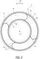
FIG. 2 is a cross-sectional view of the rotary connector device shown inFIG. 1 . -
FIG. 3 is a perspective view of a cable connector assembly of the rotary connector device shown inFIG. 1 . -
FIG. 4 is an exploded plan view of the cable connector assembly shown inFIG. 3 . -
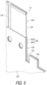
FIG. 5 is a partial perspective view of a first flat cable of the cable connector assembly shown inFIG. 3 . -
FIG. 6 is a partial perspective view of a second flat cable of the cable connector assembly shown inFIG. 3 . -
FIG. 7 is a cross-sectional view of the cable connector assembly taken along the line VII-VII inFIG. 8 . -
FIG. 8 is a partial plan view of the cable connector assembly shown inFIG. 3 . -
FIG. 9 is a cross-sectional view of the cable connector assembly taken along the line IX-IX inFIG. 8 . -
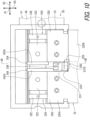
FIG. 10 is a partial plan view of a cable connector assembly according to a second embodiment. -
FIG. 11 is a cross-sectional view of the cable connector assembly taken along the line XI-XI inFIG. 10 . -
FIG. 12 is a partial plan view of a cable connector assembly according to a third embodiment. -
FIG. 13 is a cross-sectional view of the cable connector assembly taken along the line XIII-XIII inFIG. 12 . -
FIG. 14 is a partial perspective view of the cable connector of the cable connector assembly shown inFIG. 12 . -
FIG. 15 is a cross-sectional view of a cable connector assembly according to a modified example. - Embodiments will be described below with reference to the drawings. In the drawings, the same reference signs indicate corresponding or identical configurations.
- As shown in
FIG. 1 , therotary connector device 2 includes astator 10 and arotator 20. Thestator 10 is configured to be attached to a vehicle body. Therotator 20 is rotatable about a rotational axis relative to thestator 10. Therotator 20 is configured to be connected to a steering wheel. - The
rotary connector device 2 includes acable connector assembly 30. Thecable connector assembly 30 includes acable connector 31. Thecable connector assembly 30 includes acable connector 39. Thecable connector 39 has substantially the same structure as the structure of thecable connector 31. Therefore, thecable connector 31 will be described here, and the description of thecable connector 39 will be omitted. The description of thecable connector 31 can be applied to thecable connector 39. - In the present embodiment, the
rotary connector device 2 includes acable connector assembly 130. Thecable connector assembly 130 includescable connectors cable connector assembly 130 has substantially the same structure as the structure of thecable connector assembly 30. Thecable connectors cable connector 31. Accordingly, thecable connector assembly 30 will be described here, and the description of thecable connector assembly 130 will be omitted. The description of thecable connector assembly 30 can be applied to thecable connector assembly 130. - The
stator 10 includes aconnector mounting portion 41. Therotator 20 includes aconnector mounting portion 49. Thecable connector 31 is attached to theconnector mounting portion 41, and thecable connector 39 is attached to theconnector mounting portion 49. - The
cable connector 31,cable connector 131, and theconnector mounting portion 41 constitute an electrical connector EC1. Thecable connector 39,cable connector 139, and theconnector mounting portion 49 constitute an electrical connector EC9. The electrical connector EC1 is configured so that a vehicle-side connector is detachably attached to. The vehicle-side connector is electrically connected to an electric circuit of a control device or the like. The electrical connector EC9 is configured so that a steering-side connector is detachably attached to. The steering-side connector is electrically connected to electric circuits of switches of the steering wheel, an airbag device, or the like. The vehicle-side and steering-side connectors may also be referred to as external connectors. - As shown in
FIG. 2 , thestator 10 androtator 20 form acable housing space 50 provided to surround the rotational axis A1. For example, thecable housing space 50 is annular and extends in a circumferential direction D4 relative to the rotational axis A1. - The
cable connector assembly 30 includes a firstflat cable 32 and a secondflat cable 33. The firstflat cable 32 and the secondflat cable 33 are electrically connected to the cable connector 31 (see, for example,FIG. 1 ). The firstflat cable 32 and the secondflat cable 33 are electrically connected to the cable connector 39 (see, for example,FIG. 1 ). In other words, each of the firstflat cable 32 and the secondflat cable 33 electrically connects thecable connectors 31 and 39 (see, for example,FIG. 1 ). - The first
flat cable 32 and the secondflat cable 33 are disposed in thecable housing space 50. Each of the firstflat cable 32 and the secondflat cable 33 is wound around an outercylindrical portion 10A of thestator 10 and an innercylindrical portion 20A of therotator 20 so that the electrical connection between thecable connectors rotator 20 rotates relative to thestator 10. - Similarly, the
cable connector assembly 130 includes a firstflat cable 132 and a secondflat cable 133. The firstflat cable 132 and the secondflat cable 133 are electrically connected to the cable connector 131 (see, for example,FIG. 1 ). The firstflat cable 132 and the secondflat cable 133 are also electrically connected to the cable connector 139 (see, for example,FIG. 1 ). In other words, each of the firstflat cable 132 and the secondflat cable 133 electrically connects thecable connectors 131 and 139 (see, for example,FIG. 1 ). - The first
flat cable 132 and the secondflat cable 133 are disposed in thecable housing space 50. The firstflat cable 132 and the secondflat cable 133 are wound around the outercylindrical portion 10A of thestator 10 and the innercylindrical portion 20A of therotator 20 so that the electrical connection between thecable connectors rotator 20 rotates relative to thestator 10. - As shown in
FIG. 3 , thecable connector 31 includes afirst bus bar 34A, asecond bus bar 35A, and aconnector body 36. In the present embodiment, thecable connector 31 also includes afirst bus bar 34B and asecond bus bar 35B. However, the total number of bus bars is not limited to the present embodiment. For example, at least one of thefirst bus bar 34B and thesecond bus bar 35B may be omitted from thecable connector 31, or thecable connector 31 may include another bus bar in addition to thefirst bus bars second bus bars - The
first bus bar 34A has conductivity. Thefirst bus bar 34A includes a conductive material. Thefirst bus bar 34B has conductivity. Thefirst bus bar 34B includes a conductive material. - The
second bus bar 35A has conductivity. Thesecond bus bar 35A includes a conductive material. Thesecond bus bar 35B has conductivity. Thesecond bus bar 35B includes a conductive material. - The
connector body 36 has electrical insulation and partially covers thefirst bus bar 34A and thesecond bus bar 35A. Theconnector body 36 partially covers thefirst bus bars second bus bars connector body 36 includes an electrical insulation material. - The
first bus bar 34A is partially exposed from theconnector body 36. Thesecond bus bar 35A is partially exposed from theconnector body 36. Thefirst bus bar 34B is partially exposed from theconnector body 36. Thesecond bus bar 35B is partially exposed from theconnector body 36. For example, thefirst bus bars second bus bars connector body 36 by insert molding. However, thefirst bus bars second bus bars connector body 36 by methods other than insert molding. - The
first bus bar 34A includes a first connection pin 34PA and a first cable connection portion 34CA. The first connection pin 34PA is exposed from theconnector body 36 to be electrically connected to the conductor of the vehicle-side or steering-side connector. The first connection pin 34PA protrudes from theconnector body 36. The first cable connection portion 34CA is exposed from theconnector body 36 to be electrically connected to the firstflat cable 32. - The
first bus bar 34B includes a first connection pin 34PB and a first cable connection portion 34CB. The first connection pin 34PB is exposed from theconnector body 36 to be electrically connected to the conductor of the vehicle-side or steering-side connector. The first connection pin 34PB protrudes from theconnector body 36. The first cable connection portion 34CB is exposed from theconnector body 36 to be electrically connected to the firstflat cable 32. - The
second bus bar 35A includes a second connection pin 35PA and a second cable connection portion 35CA. The second connection pin 35PA is exposed from theconnector body 36 to be electrically connected to the conductor of the vehicle-side or steering-side connector. The second connection pin 35PA protrudes from theconnector body 36. The second cable connection portion 35CA is exposed from theconnector body 36 to be electrically connected to the secondflat cable 33. - The
second bus bar 35B includes a second connection pin 35PB and a second cable connection portion 35CB. The second connection pin 35PB is exposed from theconnector body 36 to be electrically connected to the conductor of a vehicle-side or steering-side connector. The second connection pin 35PB protrudes from theconnector body 36. The second cable connection portion 35CB is exposed from theconnector body 36 to be electrically connected to the secondflat cable 33. - As shown in
FIG. 4 , the firstflat cable 32 is flexible and has a flat shape. The firstflat cable 32 may also be referred to as a first flexibleflat cable 32. - The second
flat cable 33 is flexible and has a flat shape. The secondflat cable 33 may also be referred to as a second flexibleflat cable 33. - The first
flat cable 32 includes a firstconductor connection portion 32A and a firstconductor exposure portion 32B. The firstconductor connection portion 32A is electrically connected to thefirst bus bar 34A. The firstconductor connection portion 32A is electrically connected to thefirst bus bars conductor connection portion 32A is connected to thefirst bus bars conductor connection portion 32A may be electrically connected to thefirst bus bars - The first
conductor exposure portion 32B is provided at a position different from a position of the firstconductor connection portion 32A. For example, the firstconductor exposure portion 32B is provided along a part of the contour of the firstflat cable 32. - The second
flat cable 33 has flexibility and has a flat shape. The secondflat cable 33 may also be referred to as the second flexible flat cable. The secondflat cable 33 includes a secondconductor connection portion 33A and a secondconductor exposure portion 33B. The secondconductor connection portion 33A is electrically connected to thesecond bus bar 35A. The secondconductor connection portion 33A is electrically connected to the second bus bars 35B. For example, the secondconductor connection portion 33A is connected to thesecond bus bars conductor connection portion 33A may be electrically connected to thesecond bus bars - The second
conductor exposure portion 33B is provided at a position different from a position of the secondconductor connection portion 33A. For example, the secondconductor exposure portion 33B is provided along a part of the contour of the secondflat cable 33. - As shown in
FIG. 5 , in the present embodiment, the firstflat cable 32 includes afirst conductor 32C and afirst insulation cover 32D. Thefirst conductor 32C includes a conductive material. Thefirst insulation cover 32D includes an electrical insulation material and partially covers thefirst conductor 32C. Thefirst conductor 32C is exposed from thefirst insulation cover 32D at the firstconductor connection portion 32A. Thefirst conductor 32C is exposed from thefirst insulation cover 32D at the firstconductor exposure portion 32B. Thefirst conductor 32C is electrically connected to thefirst bus bar 34A. Thefirst insulation cover 32D includes first insulators 32D1 and 32D2. Thefirst conductor 32C is disposed between the first insulators 32D1 and 32D2. - For example, the first
conductor connection portion 32A is formed by not forming thefirst insulation cover 32D on thefirst conductor 32C or by peeling off a portion of thefirst insulation cover 32D from thefirst conductor 32C. On the other hand, the firstconductor exposure portion 32B is provided at a cut surface formed when the firstflat cable 32 is cut from the flat cable material. - The first
flat cable 32 includes a firstadditional conductor 32E. Thefirst insulation cover 32D partially covers the firstadditional conductor 32E. The firstadditional conductor 32E is exposed from thefirst insulation cover 32D at the firstconductor connection portion 32A. The firstadditional conductor 32E is electrically connected to thefirst bus bar 34B at the firstconductor connection portion 32A. The firstadditional conductor 32E is connected to the first cable connection portion 34CB at the firstconductor connection portion 32A. The firstadditional conductor 32E is not exposed from thefirst insulation cover 32D at the firstconductor exposure portion 32B. However, the firstadditional conductor 32E may be exposed from thefirst insulation cover 32D at the firstconductor exposure portion 32B. - As shown in
FIG. 6 , in the present embodiment, the secondflat cable 33 includes asecond conductor 33C and asecond insulation cover 33D. Thesecond conductor 33C includes a conductive material. Thesecond insulation cover 33D includes an electrical insulation material and partially covers thesecond conductor 33C. Thesecond conductor 33C is exposed from thesecond insulation cover 33D at the secondconductor connection portion 33A. Thesecond conductor 33C is exposed from thesecond insulation cover 33D at the secondconductor exposure portion 33B. Thesecond conductor 33C is electrically connected to thesecond bus bar 35A. Thesecond insulation cover 33D includes second insulators 33D1 and 33D2. Thesecond conductor 33C is disposed between the second insulators 33D1 and 33D2. - For example, the second
conductor connection portion 33A is formed by not forming thesecond insulation cover 33D on thesecond conductor 33C or by peeling off a portion of thesecond insulation cover 33D from thesecond conductor 33C. On the other hand, the secondconductor exposure portion 33B is provided at a cut surface formed when the secondflat cable 33 is cut from the flat cable material. - The second
flat cable 33 includes a secondadditional conductor 33E. Thesecond insulation cover 33D partially covers the secondadditional conductor 33E. The secondadditional conductor 33E is exposed from thesecond insulation cover 33D at the secondconductor connection portion 33A. The secondadditional conductor 33E is electrically connected to thesecond bus bar 35B at the secondconductor connection portion 33A. The secondadditional conductor 33E is connected to the second cable connection portion 35CB at the secondconductor connection portion 33A. The secondadditional conductor 33E is not exposed from thesecond insulation cover 33D at the secondconductor exposure portion 33B. However, the secondadditional conductor 33E may be exposed from thesecond insulation cover 33D at the secondconductor exposure portion 33B. - As shown in
FIG. 4 , thefirst conductor 32C is electrically connected to thefirst bus bar 34A at the firstconductor connection portion 32A. Thefirst conductor 32C is connected to the first cable connection portion 34CA at the firstconductor connection portion 32A. - The first
additional conductor 32E is electrically connected to thefirst bus bar 34B at the firstconductor connection portion 32A. The firstadditional conductor 32E is connected to the first cable connection portion 34CB at the firstconductor connection portion 32A. - The
second conductor 33C is electrically connected to thesecond bus bar 35A at the secondconductor connection portion 33A. Thesecond conductor 33C is connected to the second cable connection portion 35CA at the secondconductor connection portion 33A. - The second
additional conductor 33E is electrically connected to thesecond bus bar 35B at the secondconductor connection portion 33A. The secondadditional conductor 33E is connected to the second cable connection portion 35CB at the secondconductor connection portion 33A. - As shown in
FIG. 7 , thecable connector 31 includes afirst surface 31A and asecond surface 31B provided on a reverse side of thefirst surface 31A in the first direction D1. The firstflat cable 32 and the secondflat cable 33 are provided on thefirst surface 31A. Theconnector body 36 includes thefirst surface 31A and thesecond surface 31B. The first direction D1 corresponds to a vertical direction inFIG. 7 . - The second
flat cable 33 is provided partially between thefirst surface 31A and the firstflat cable 32 in the first direction D1. In the present embodiment, the secondflat cable 33 is provided partially between thefirst surface 31A and the firstflat cable 32 in the first direction D1. However, the secondflat cable 33 may be provided entirely between thefirst surface 31A and the firstflat cable 32 in the first direction D1. - As shown in
FIG. 8 , the firstflat cable 32 is disposed to partially overlap the secondflat cable 33 when viewed from the first direction D1. The firstconductor connection portion 32A is disposed not to overlap the secondconductor connection portion 33A when viewed from the first direction D1. The firstconductor connection portion 32A is disposed with a space between the secondconductor connection portion 33A in the second direction D2. The second direction D2 is perpendicular to the first direction D1. The firstconductor connection portion 32A is provided at the end of the firstflat cable 32. The secondconductor connection portion 33A is provided at the end of the secondflat cable 33. The firstflat cable 32 extends from the firstconductor connection portion 32A in the third direction D3. The secondflat cable 33 extends from the secondconductor connection portion 33A in the third direction D3. The third direction D3 is perpendicular to both the first direction D1 and the second direction D2. The second direction D2 corresponds to the left-right direction inFIG. 8 . The third direction D3 corresponds to the vertical direction inFIG. 8 . - The first
conductor exposure portion 32B is disposed to at least partially overlap the secondconductor exposure portion 33B when viewed from the first direction D1. In the present embodiment, the firstconductor exposure portion 32B is disposed to partially overlap the secondconductor exposure portion 33B when viewed from the first direction D1. However, the firstconductor exposure portion 32B may be disposed to entirely overlap the secondconductor exposure portion 33B when viewed from the first direction D1. - The first
flat cable 32 includes amain body portion 32F and an overlappingportion 32G. Themain body portion 32F includes the firstconductor connection portion 32A. The overlappingportion 32G at least partially includes the firstconductor exposure portion 32B and is disposed to at least partially overlap the secondconductor exposure portion 33B when viewed from the first direction D1. In the present embodiment, the overlappingportion 32G is disposed to partially overlap the secondconductor exposure portion 33B when viewed from the first direction D1. However, the overlappingportion 32G may be disposed to entirely overlap the secondconductor exposure portion 33B when viewed from the first direction D1. - The first
flat cable 32 includes aslit 32S provided between themain body portion 32F and the overlappingportion 32G. Themain body portion 32F includes a first main body portion 32FA and a second main body portion 32FB. The first main body portion 32FA includes the firstconductor connection portion 32A. The second main body portion 32FB extends from the first main body portion 32FA. The overlappingportion 32G extends from the second main body portion 32FB. Theslit 32S is provided between the first main body portion 32FA and the overlappingportion 32G in the second direction D2. Theslit 32S may also be a cut. - As shown in
FIG. 9 , thecable connector 31 includes arestriction portion 37. Therestriction portion 37 is contactable with the firstflat cable 32 in the first direction D1 to restrict the firstconductor exposure portion 32B from moving toward the secondconductor exposure portion 33B. Therestriction portion 37 protrudes from thefirst surface 31A of theconnector body 36 in the first direction D1. - In the present embodiment, the
restriction portion 37 is integrally provided with theconnector body 36 as a one-piece member. However, therestriction portion 37 may be a separate member from theconnector body 36. In that case, for example, therestriction portion 37 may be attached to theconnector body 36 using an attachment structure such as adhesion or press-fitting. - The
restriction portion 37 is contactable with the overlappingportion 32G to restrict the overlappingportion 32G from moving toward the secondconductor exposure portion 33B in the first direction D1. In the present embodiment, therestriction portion 37 includes acontact surface 37A contactable with the overlappingportion 32G. Thecontact surface 37A includes aninclined surface 37B inclined relative to the first direction D1. The overlappingportion 32G is inclined relative to themain body portion 32F in a state where therestriction portion 37 restricts the firstconductor exposure portion 32B from moving toward the secondconductor exposure portion 33B. The overlappingportion 32G is inclined relative to themain body portion 32F in a state where the overlappingportion 32G is in contact with theinclined surface 37B. However, theinclined surface 37B may be omitted from thecontact surface 37A. Thecontact surface 37A may be disposed not to be inclined relative to the first direction D1. - As shown in
FIG. 9 , the firstflat cable 32 has a first thickness W1 defined in the first direction D1 in the state where the firstconductor connection portion 32A is electrically connected to thefirst bus bar 34A. The secondflat cable 33 has a second thickness W2 defined in the first direction D1 in the state where the secondconductor connection portion 33A is electrically connected to thesecond bus bar 35A. Therestriction portion 37 has a protrusion length L1 defined in the first direction D1 from thefirst surface 31A. The protrusion length L1 is greater than the second thickness W2. In the present embodiment, the protrusion length L1 is greater than the total of the first thickness W1 and the second thickness W2. However, the protrusion length L1 may be less than or equal to the total of the first thickness W1 and the second thickness W2. - As shown in
FIG. 8 , therestriction portion 37 is disposed to partially overlap the firstflat cable 32 when viewed from the first direction D1. Therestriction portion 37 is disposed not to overlap the secondflat cable 33 when viewed from the first direction D1. The overlappingportion 32G is disposed to at least partially overlap therestriction portion 37 when viewed from the first direction D1. In the present embodiment, the overlappingportion 32G is disposed to partially overlap therestriction portion 37 when viewed from the first direction D1. However, the overlappingportion 32G may be disposed to entirely overlap therestriction portion 37 when viewed from the first direction D1. - The overlapping
portion 32G protrudes from themain body portion 32F when viewed from the first direction D1 in a state where therestriction portion 37 restricts the firstconductor exposure portion 32B from moving toward the secondconductor exposure portion 33B. The overlappingportion 32G protrudes from themain body portion 32F toward the firstconductor connection portion 32A when viewed from the first direction D1 in a state where therestriction portion 37 restricts the firstconductor exposure portion 32B from moving toward the secondconductor exposure portion 33B. The overlappingportion 32G is disposed not to overlap themain body portion 32F when viewed from the first direction D1 in a state where therestriction portion 37 restricts the firstconductor exposure portion 32B from moving toward the secondconductor exposure portion 33B. However, the overlappingportion 32G may be disposed to protrude from themain body portion 32F in another direction. The overlappingportion 32G may be disposed to at least partially overlap themain body portion 32F when viewed from the first direction D1 in a state where therestriction portion 37 restricts the firstconductor exposure portion 32B from moving toward the secondconductor exposure portion 33B. - As described above, the
cable connector assembly 30 includes thecable connector 31, the firstflat cable 32, and the secondflat cable 33. Thecable connector 31 includes thefirst bus bar 34A having conductivity, thesecond bus bar 35A having conductivity, and theconnector body 36 having electrical insulation and partially covering thefirst bus bar 34A and thesecond bus bar 35A. The firstflat cable 32 includes the firstconductor connection portion 32A electrically connected to thefirst bus bar 34A and the firstconductor exposure portion 32B provided at the position different from the position of the firstconductor connection portion 32A. The secondflat cable 33 includes the secondconductor connection portion 33A electrically connected to thesecond bus bar 35A and the secondconductor exposure portion 33B provided at the position different from the position of the secondconductor connection portion 33A. Thecable connector 31 includes thefirst surface 31A and thesecond surface 31B provided on the reverse side of thefirst surface 31A in the first direction D1. The firstflat cable 32 is disposed to partially overlap the secondflat cable 33 when viewed from the first direction D1. The secondflat cable 33 is partially provided between thefirst surface 31A and the firstflat cable 32 in the first direction D1. Thecable connector 31 includes therestriction portion 37 contactable with the firstflat cable 32 to restrict the firstconductor exposure portion 32B from moving toward the secondconductor exposure portion 33B in the first direction D1. - With the
cable connector assembly 30, since therestriction portion 37 restricts the firstconductor exposure portion 32B from moving toward the secondconductor exposure portion 33B in the first direction D1, it is possible to suppress or prevent short-circuiting between the firstconductor exposure portion 32B and the secondconductor exposure portion 33B with a relatively simple structure. Therefore, it is possible to suppress or prevent short-circuiting between the firstflat cable 32 and the secondflat cable 33 while suppressing the increase in the manufacturing cost. - A
cable connector assembly 230 according to the second embodiment will be described below with reference toFIGS. 10 and11 . Except for therestriction portion 37, thecable connector assembly 230 has substantially the same structure as thecable connector assembly 30 according to the first embodiment. Therefore, components having substantially the same structure as those in the first embodiment are assigned the same reference numbers, and for simplification, they are not described and/or illustrated in detail again here. - As shown in
FIG. 10 , thecable connector assembly 230 includes a cable connector 231, the firstflat cable 32, and the secondflat cable 33. The cable connector 231 has substantially the same structure as thecable connector 31 of the first embodiment. - As shown in
FIG. 11 , the cable connector 231 includes arestriction portion 237. Therestriction portion 237 is contactable with the firstflat cable 32 in the first direction D1 to restrict the firstconductor exposure portion 32B from moving toward the secondconductor exposure portion 33B. Therestriction portion 237 protrudes from thefirst surface 31A of theconnector body 36 in the first direction D1. - In the present embodiment, the
restriction portion 237 is integrally provided with theconnector body 36 as a one-piece member. However, therestriction portion 237 may be a separate member from theconnector body 36. In that case, for example, therestriction portion 237 may be attached to theconnector body 36 using an attachment structure such as adhesion or press-fitting. - The
restriction portion 237 is contactable with the overlappingportion 32G to restrict the overlappingportion 32G from moving toward the secondconductor exposure portion 33B in the first direction D1. In the present embodiment, therestriction portion 237 includes asupport groove 237G contactable with the overlappingportion 32G to restrict the firstconductor exposure portion 32B from moving toward the secondconductor exposure portion 33B in the first direction D1. The overlappingportion 32G is at least partially disposed in thesupport groove 237G. The overlappingportion 32G is disposed in thesupport groove 237G in a bent state relative to themain body portion 32F. - The
restriction portion 237 has a protrusion length L2 defined in the first direction D1 from thefirst surface 31A. The protrusion length L2 is greater than the second thickness W2. In the present embodiment, the protrusion length L2 is greater than the total of the first thickness W1 and the second thickness W2. However, the protrusion length L2 may be less than or equal to the total of the first thickness W1 and the second thickness W2. - As shown in
FIG. 10 , therestriction portion 237 is disposed to partially overlap the firstflat cable 32 when viewed from the first direction D1. Therestriction portion 237 is disposed not to overlap the secondflat cable 33 when viewed from the first direction D1. The overlappingportion 32G is disposed to at least partially overlap therestriction portion 237 when viewed from the first direction D1. In the present embodiment, the overlappingportion 32G is disposed to partially overlap therestriction portion 237 when viewed from the first direction D1. However, the overlappingportion 32G may be disposed to entirely overlap therestriction portion 237 when viewed from the first direction D1. - The overlapping
portion 32G protrudes from themain body portion 32F when viewed from the first direction D1 in a state where therestriction portion 237 restricts the firstconductor exposure portion 32B from moving toward the secondconductor exposure portion 33B. The overlappingportion 32G protrudes toward the firstconductor connection portion 32A from themain body portion 32F when viewed from the first direction D1 in a state where therestriction portion 237 restricts the firstconductor exposure portion 32B from moving toward the secondconductor exposure portion 33B. The overlappingportion 32G is disposed not to overlap themain body portion 32F when viewed from the first direction D1 in a state where therestriction portion 237 restricts the firstconductor exposure portion 32B from moving toward the secondconductor exposure portion 33B. However, the overlappingportion 32G may be disposed to protrude from themain body portion 32F in another direction. The overlappingportion 32G may be disposed to at least partially overlap themain body portion 32F when viewed from the first direction D1 in a state where therestriction portion 237 restricts the firstconductor exposure portion 32B from moving toward the secondconductor exposure portion 33B. - The overlapping
portion 32G is disposed to at least partially overlap themain body portion 32F when viewed from the first direction D1 in a state where the overlappingportion 32G is disposed in thesupport groove 237G. In the present embodiment, the overlappingportion 32G is disposed to partially overlap themain body portion 32F when viewed from the first direction D1 in a state where the overlappingportion 32G is disposed in thesupport groove 237G. However, the overlappingportion 32G may be disposed to entirely overlap themain body portion 32F when viewed from the first direction D1 in a state where the overlappingportion 32G is disposed in thesupport groove 237G. - As described above, the
cable connector assembly 230 includes thecable connector 31, the firstflat cable 32, and the secondflat cable 33. Thecable connector 31 includes thefirst bus bar 34A having conductivity, thesecond bus bar 35A having conductivity, and theconnector body 36 having electrical insulation and partially covering thefirst bus bar 34A and thesecond bus bar 35A. The firstflat cable 32 includes the firstconductor connection portion 32A electrically connected to thefirst bus bar 34A and the firstconductor exposure portion 32B provided at the position different from the position of the firstconductor connection portion 32A. The secondflat cable 33 includes the secondconductor connection portion 33A electrically connected to thesecond bus bar 35A and the secondconductor exposure portion 33B provided at the position different from the position of the secondconductor connection portion 33A. Thecable connector 31 includes thefirst surface 31A and thesecond surface 31B provided on a reverse side of thefirst surface 31A in the first direction D1. The firstflat cable 32 is disposed to partially overlap the secondflat cable 33 when viewed from the first direction D1. The secondflat cable 33 is partially provided between thefirst surface 31A and the firstflat cable 32 in the first direction D1. Thecable connector 31 includes therestriction portion 237 contactable with the firstflat cable 32 to restrict the firstconductor exposure portion 32B from moving toward the secondconductor exposure portion 33B in the first direction D1. - With the
cable connector assembly 230, since therestriction portion 237 restricts the firstconductor exposure portion 32B from moving toward the secondconductor exposure portion 33B in the first direction D1, it is possible to suppress or prevent short-circuiting between the firstconductor exposure portion 32B and the secondconductor exposure portion 33B with a relatively simple structure. Therefore, it is possible to suppress or prevent short-circuiting between the firstflat cable 32 and the secondflat cable 33 while suppressing the increase in the manufacturing cost. - A
cable connector assembly 330 according to the third embodiment will be described below with reference toFIGS. 12 to 14 . Except for therestriction portion 37, thecable connector assembly 330 has substantially the same structure as thecable connector assembly 30 according to the first embodiment. Therefore, components having substantially the same structure as those in the first embodiment are assigned the same reference numbers, and for simplification, these components are not described and/or illustrated in detail again here. - As shown in
FIG. 12 , thecable connector assembly 330 includes a cable connector 331, the firstflat cable 32, and the secondflat cable 33. The cable connector 331 has substantially the same structure as thecable connector 31 of the first embodiment. - As shown in
FIG. 13 , the cable connector 331 includes arestriction portion 337. Therestriction portion 337 is contactable with the firstflat cable 32 in the first direction D1 to restrict the firstconductor exposure portion 32B from moving toward the secondconductor exposure portion 33B. Therestriction portion 337 protrudes from thefirst surface 31A of theconnector body 36 in the first direction D1. Therestriction portion 337 has substantially the same structure as therestriction portion 37 of the first embodiment. - In the present embodiment, the
restriction portion 337 is integrally provided with theconnector body 36 as a one-piece member. However, therestriction portion 337 may be a separate member from theconnector body 36. In that case, for example, therestriction portion 337 may be attached to theconnector body 36 using an attachment structure such as adhesion or press-fitting. - The
restriction portion 337 is contactable with the overlappingportion 32G to restrict the overlappingportion 32G from moving toward the secondconductor exposure portion 33B in the first direction D1. In the present embodiment, therestriction portion 337 includes acontact surface 337A contactable with the overlappingportion 32G. Thecontact surface 337A includes aninclined surface 337B inclined relative to the first direction D1. The overlappingportion 32G is inclined relative to themain body portion 32F in a state where therestriction portion 337 restricts the firstconductor exposure portion 32B from moving toward the secondconductor exposure portion 33B. Therestriction portion 337 is contactable with the overlappingportion 32G to restrict the overlappingportion 32G from moving toward the secondconductor exposure portion 33B in the first direction D1. The overlappingportion 32G is inclined relative to themain body portion 32F in a state where the overlappingportion 32G is in contact with theinclined surface 337B. However, theinclined surface 337B may be omitted from thecontact surface 337A. Thecontact surface 337A may be disposed not to be inclined relative to the first direction D1. - In the present embodiment, the
cable connector assembly 330 further comprises a holdingportion 339 provided to therestriction portion 337. The holdingportion 339 is contactable with the firstflat cable 32 to restrict the firstconductor exposure portion 32B from moving away from the secondconductor exposure portion 33B in the first direction D1. The holdingportion 339 is contactable with the firstflat cable 32 to restrict the firstconductor exposure portion 32B from moving toward the secondconductor exposure portion 33B in the first direction D1. That is, the holdingportion 339 is configured to hold the firstflat cable 32 to restrict the firstconductor exposure portion 32B from moving toward the secondconductor exposure portion 33B in the first direction D1. - The holding
portion 339 protrudes from therestriction portion 337 in the first direction D1. The firstflat cable 32 includes a holdingopening 32H. The holdingportion 339 protrudes from therestriction portion 337 through the holdingopening 32H in the first direction D1. However, the contact portion between the firstflat cable 32 and the holdingportion 339 may have other structures. For example, the holdingportion 339 may have a groove, and the firstflat cable 32 may be inserted into the groove. As shown inFIG. 12 , the holdingopening 32H includes a notch. However, the holdingopening 32H may include a hole into which the holdingportion 339 is inserted. - In the present embodiment, the holding
portion 339 is integrally provided with therestriction portion 337 as a one-piece member. However, the holdingportion 339 may be a separate member from therestriction portion 337. In that case, for example, the holdingportion 339 may be attached to therestriction portion 337 using an attachment structure such as adhesion or press-fitting. - As shown in
FIG. 14 , the holdingportion 339 is provided on thecontact surface 337A of therestriction portion 337 and protrudes from thecontact surface 337A in the first direction D1. Thecontact surface 337A includes anadditional contact surface 337C. For example, theadditional contact surface 337C is perpendicular to the first direction D1. Theadditional contact surface 337C is inclined relative to theinclined surface 337B. Theadditional contact surface 337C extends from theinclined surface 337B in the third direction D3. The holdingportion 339 is provided on theadditional contact surface 33 and protrudes from theadditional contact surface 337C in the first direction D1. However, theadditional contact surface 337C may be inclined relative to the first direction D1. The holdingportion 339 may protrude from theinclined surface 337B. - As shown in
FIG. 13 , therestriction portion 337 has a protrusion length L3 defined in the first direction D1 from thefirst surface 31A. The protrusion length L3 is defined in the first direction D1 from thefirst surface 31A to theadditional contact surface 337C of thecontact surface 337A. The protrusion length L3 is greater than the second thickness W2. In the present embodiment, the protrusion length L3 is greater than the total of the first thickness W1 and the second thickness W2. However, the protrusion length L3 may be less than or equal to the total of the first thickness W1 and the second thickness W2. - The holding
portion 339 has an additional protrusion length L4. The additional protrusion length L4 is defined in the first direction D1 from thecontact surface 337A of therestriction portion 337 to the end of the holdingportion 339. In the present embodiment, the additional protrusion length L4 is greater than the protrusion length L3. The additional protrusion length L4 is greater than the first thickness W1. However, the additional protrusion length L4 may be equal to or less than the protrusion length L3. The additional protrusion length L4 may be equal to or less than the first thickness W1. - As shown in
FIG. 12 , therestriction portion 337 is disposed to partially overlap the firstflat cable 32 when viewed from the first direction D1. Therestriction portion 337 is disposed not to overlap the secondflat cable 33 when viewed from the first direction D1. The overlappingportion 32G is disposed to at least partially overlap therestriction portion 337 when viewed from the first direction D1. In the present embodiment, the overlappingportion 32G is disposed to partially overlap therestriction portion 337 when viewed from the first direction D1. However, the overlappingportion 32G may be disposed to entirely overlap therestriction portion 337 when viewed from the first direction D1. - The overlapping
portion 32G protrudes from themain body portion 32F when viewed from the first direction D1 in a state where therestriction portion 337 restricts the firstconductor exposure portion 32B from moving toward the secondconductor exposure portion 33B. The overlappingportion 32G protrudes toward the firstconductor connection portion 32A from themain body portion 32F when viewed from the first direction D1 in a state where therestriction portion 337 restricts the firstconductor exposure portion 32B from moving toward the secondconductor exposure portion 33B. The overlappingportion 32G is disposed not to overlap themain body portion 32F when viewed from the first direction D1 in a state where therestriction portion 337 restricts the firstconductor exposure portion 32B from moving toward the secondconductor exposure portion 33B. However, the overlappingportion 32G may be disposed to protrude from themain body portion 32F in another direction. The overlappingportion 32G may be disposed to at least partially overlap themain body portion 32F when viewed from the first direction D1 in a state where therestriction portion 337 restricts the firstconductor exposure portion 32B from moving toward the secondconductor exposure portion 33B. - As shown in
FIG. 15 , by melting the holdingportion 339 after the attachment of the firstflat cable 32, the firstflat cable 32 can be held between therestriction portion 337 and the holdingportion 339. By holding the firstflat cable 32 between therestriction portion 337 and the holdingportion 339, it is possible to more reliably restrict the firstflat cable 32 from moving in the first direction D1 relative to therestriction portion 337, making the posture of the firstflat cable 32 more stable. - As described above, the
cable connector assembly 330 includes thecable connector 31, the firstflat cable 32, and the secondflat cable 33. Thecable connector 31 includes thefirst bus bar 34A having conductivity, thesecond bus bar 35A having conductivity, and theconnector body 36 having electrical insulation and partially covering thefirst bus bar 34A and thesecond bus bar 35A. The firstflat cable 32 includes the firstconductor connection portion 32A electrically connected to thefirst bus bar 34A and the firstconductor exposure portion 32B provided in the position different from the position of the firstconductor connection portion 32A. The secondflat cable 33 includes the secondconductor connection portion 33A electrically connected to thesecond bus bar 35A and the secondconductor exposure portion 33B provided in the position different from the position of the secondconductor connection portion 33A. Thecable connector 31 includes thefirst surface 31A and thesecond surface 31B provided on a reverse side of thefirst surface 31A in the first direction D1. The firstflat cable 32 is disposed to partially overlap the secondflat cable 33 when viewed from the first direction D1. The secondflat cable 33 is provided partially between thefirst surface 31A and the firstflat cable 32 in the first direction D1. Thecable connector 31 includes arestriction portion 337 contactable with the firstflat cable 32 in the first direction D1 to restrict the firstconductor exposure portion 32B from moving toward the secondconductor exposure portion 33B. - With the
cable connector assembly 330, therestriction portion 337 restricts the firstconductor exposure portion 32B from moving toward the secondconductor exposure portion 33B in the first direction D1, it is possible to suppress or prevent short-circuiting between the firstconductor exposure portion 32B and the secondconductor exposure portion 33B with a relatively simple structure. Therefore, it is possible to suppress or prevent short-circuiting between the firstflat cable 32 and the secondflat cable 33 while suppressing the increase in the manufacturing cost. - In the present application, the term "comprising" and its derivatives are openended terms that describe the presence of constituent elements and do not exclude the presence of other constituent elements not described. This concept also applies to the terms "having," "including," and their derivatives.
- In the present application, ordinal numbers such as "first" and "second" are merely identifiers, but do not have any other meanings (e.g., a particular order and the like). For example, the term "first element" does not imply an existence of "second element," and the term "second element" does not imply an existence of "first element."
- In the present disclosure, the expressions "parallel," "perpendicular," and "coincident" should not be strictly interpreted, and include the meanings "substantially parallel," "substantially perpendicular," and "substantially coincident," respectively. Other expressions relating to arrangements are not strictly interpreted.
- The phrase "at least one of A and B" in the present disclosure encompasses, for example, (1) A alone, (2) B alone, and (3) both A and B. The phrase "at least one of A, B, and C" encompasses, for example, (1) A alone, (2) B alone, (3) C alone, (4) A and B, (5) B and C, (6) A and C, and (7) all A, B, and C. In the present disclosure, the phrase "at least one of A and B" is not interpreted as "at least one of A and at least one of B."
- In view of the above disclosure, it is obvious that various changes and modifications of the present invention are possible. Therefore, the present invention may be implemented in a manner different from that of the specific disclosure of the present application to the extent that it does not depart from the intent of the present invention.
-
- 2 : Rotary connector device
- 10 : Stator
- 20 : Rotator
- 30, 130, 230 : Cable connector assembly
- 31, 39, 131, 139 : Cable connector
- 31A: First surface
- 31B : Second surface
- 32, 132 : First flat cable
- 32A : First conductor connection portion
- 32B : First conductor exposure portion
- 32C : First conductor
- 32D : First insulation cover
- 32F : Main body portion
- 32G : Overlapping portion
- 32S : Slit
- 32H : Holding opening
- 33, 133 : Second flat cable
- 33A : Second conductor connection portion
- 33B : Second conductor exposure portion
- 33C : Second conductor
- 33D : Second insulation cover
- 33E : Second additional conductor
- 34A : First bus bar
- 34B : First bus bar
- 34CA : First cable connection portion
- 34CB : First cable connection portion
- 36 : Connector body
- 37, 237, 337 : Restriction portion
- 339 : Holding portion
- 37A : Contact surface
- 37B : Inclined surface
- 50 : Cable housing space
- 237G : Support groove
- A1 : Rotational axis
- D1 : First direction
- D2 : Second direction
- D3 : Third direction
- D4 : Circumferential direction
- W1 : First thickness
- W2 : Second thickness
Claims (18)
- A cable connector assembly comprising:a cable connector includinga first bus bar having conductivity,a second bus bar having conductivity, anda connector body having electrical insulation and partially covering the first bus bar and the second bus bar;a first flat cable includinga first conductor connection portion electrically connected to the first bus bar, anda first conductor exposure portion provided at a position different from a position of the first conductor connection portion;a second flat cable includinga second conductor connection portion electrically connected to the second bus bar, anda second conductor exposure portion provided at a position different from a position of the second conductor connection portion;the cable connector including a first surface and a second surface provided on a reverse side of the first surface in a first direction;the first flat cable being disposed to partially overlap the second flat cable when viewed from the first direction;the second flat cable being provided partially between the first surface and the first flat cable in the first direction; andthe cable connector including a restriction portion contactable with the first flat cable to restrict the first conductor exposure portion from moving toward the second conductor exposure portion in the first direction.
- The cable connector assembly according to claim 1, whereinthe restriction portion is disposed to partially overlap the first flat cable when viewed from the first direction, andthe restriction portion is disposed not to overlap the second flat cable when viewed from the first direction.
- The cable connector assembly according to claim 1, wherein
the restriction portion protrudes from the first surface of the connector body in the first direction. - The cable connector assembly according to claim 3, whereinthe first flat cable has a first thickness defined in the first direction in a state where the first conductor connection portion is electrically connected to the first bus bar,the second flat cable has a second thickness defined in the first direction in a state where the second conductor connection portion is electrically connected to the second bus bar,the restriction portion has a protrusion length defined in the first direction from the first surface, andthe protrusion length is greater than the second thickness.
- The cable connector assembly according to claim 4, wherein
the protrusion length is greater than a total of the first thickness and the second thickness. - The cable connector assembly according to any one of claims 1 to 5, wherein
the restriction portion is integrally provided with the connector body. - The cable connector assembly according to any one of claims 1 to 5, wherein
the first conductor exposure portion is disposed to at least partially overlap the second conductor exposure portion when viewed from the first direction. - The cable connector assembly according to any one of claims 1 to 5, whereinthe first flat cable includesa main body portion including the first conductor connection portion, andan overlapping portion at least partially including the first conductor exposure portion and disposed to at least partially overlap the second conductor exposure portion when viewed from the first direction, andthe restriction portion is contactable with the overlapping portion to restrict the overlapping portion from moving toward the second conductor exposure portion in the first direction.
- The cable connector assembly according to claim 8, whereinthe restriction portion includes a contact surface contactable with the overlapping portion, andthe contact surface includes an inclined surface inclined relative to the first direction.
- The cable connector assembly according to claim 8, wherein
the overlapping portion is inclined relative to the main body portion in a state where the restriction portion restricts the first conductor exposure portion from moving toward the second conductor exposure portion. - The cable connector assembly according to claim 8, wherein
the overlapping portion protrudes from the main body portion when viewed from the first direction in a state where the restriction portion restricts the first conductor exposure portion from moving toward the second conductor exposure portion. - The cable connector assembly according to claim 8, whereinthe restriction portion includes a support groove contactable with the overlapping portion to restrict the first conductor exposure portion from moving toward the second conductor exposure portion in the first direction, andthe overlapping portion is at least partially disposed in the support groove.
- The cable connector assembly according to claim 12, wherein
the overlapping portion is disposed in the support groove in a bent state relative to the main body portion. - The cable connector assembly according to claim 13, wherein
the overlapping portion is disposed to at least partially overlap the main body portion when viewed from the first direction in a state where the overlapping portion is disposed in the support groove. - The cable connector assembly according to any one of claims 1 to 5, further comprisinga holding portion provided to the restriction portion, whereinthe holding portion is contactable with the first flat cable to restrict the first conductor exposure portion from moving away from the second conductor exposure portion in the first direction.
- The cable connector assembly according to claim 15, wherein
the holding portion protrudes from the restriction portion in the first direction. - The cable connector assembly according to claim 16, whereinthe first flat cable includes a holding opening, andthe holding portion protrudes from the restriction portion through the holding opening in the first direction.
- A rotary connector device comprising:a stator;a rotator rotatable about a rotational axis relative to the stator; andthe cable connector assembly according to any one of claims 1 to 5.
Applications Claiming Priority (3)
| Application Number | Priority Date | Filing Date | Title |
|---|---|---|---|
| JP2022084607 | 2022-05-24 | ||
| JP2022110716 | 2022-07-08 | ||
| PCT/JP2023/018612 WO2023228861A1 (en) | 2022-05-24 | 2023-05-18 | Flat cable assembly and rotational connector device |
Publications (2)
| Publication Number | Publication Date |
|---|---|
| EP4525222A1 true EP4525222A1 (en) | 2025-03-19 |
| EP4525222A4 EP4525222A4 (en) | 2025-09-24 |
Family
ID=88919251
Family Applications (1)
| Application Number | Title | Priority Date | Filing Date |
|---|---|---|---|
| EP23811734.5A Pending EP4525222A4 (en) | 2022-05-24 | 2023-05-18 | FLAT CABLE ARRANGEMENT AND ROTATING CONNECTOR DEVICE |
Country Status (6)
| Country | Link |
|---|---|
| US (1) | US20250079782A1 (en) |
| EP (1) | EP4525222A4 (en) |
| JP (1) | JPWO2023228861A1 (en) |
| KR (1) | KR20250016278A (en) |
| CN (1) | CN119111023A (en) |
| WO (1) | WO2023228861A1 (en) |
Family Cites Families (13)
| Publication number | Priority date | Publication date | Assignee | Title |
|---|---|---|---|---|
| JPS5833522U (en) | 1981-07-23 | 1983-03-04 | 新和コンクリ−ト工業株式会社 | Square timber dam |
| TW317043B (en) * | 1994-07-19 | 1997-10-01 | Methode Electronics Inc | |
| JP2002034139A (en) * | 2000-07-17 | 2002-01-31 | Auto Network Gijutsu Kenkyusho:Kk | Rotary connection device |
| JP5802156B2 (en) * | 2012-03-14 | 2015-10-28 | アルプス電気株式会社 | Rotating connector |
| CN103378526B (en) | 2012-04-11 | 2015-05-27 | 阿尔卑斯电气株式会社 | Rotation connector |
| JP5886148B2 (en) * | 2012-06-21 | 2016-03-16 | 株式会社ヴァレオジャパン | Rotating connector device |
| JP6249528B2 (en) * | 2014-07-04 | 2017-12-20 | アルプス電気株式会社 | Rotating connector |
| KR101691429B1 (en) * | 2015-06-22 | 2017-01-09 | (주)신창코넥타 | Steering Rolling Connector Apparatus for Vehicles |
| JP6608294B2 (en) * | 2016-01-28 | 2019-11-20 | アルプスアルパイン株式会社 | Rotating connector |
| JP6696791B2 (en) * | 2016-02-17 | 2020-05-20 | 古河電気工業株式会社 | Connector, flat cable with connector, and rotary connector device |
| JP6696840B2 (en) * | 2016-06-21 | 2020-05-20 | 古河電気工業株式会社 | Rotating connector device |
| JP2019218150A (en) * | 2018-06-15 | 2019-12-26 | 矢崎総業株式会社 | Flat cable winding device |
| JP2021190324A (en) * | 2020-06-01 | 2021-12-13 | 株式会社東海理化電機製作所 | Relay system |
-
2023
- 2023-05-18 CN CN202380036965.3A patent/CN119111023A/en active Pending
- 2023-05-18 JP JP2024523082A patent/JPWO2023228861A1/ja active Pending
- 2023-05-18 EP EP23811734.5A patent/EP4525222A4/en active Pending
- 2023-05-18 KR KR1020247042773A patent/KR20250016278A/en active Pending
- 2023-05-18 WO PCT/JP2023/018612 patent/WO2023228861A1/en not_active Ceased
-
2024
- 2024-11-18 US US18/950,167 patent/US20250079782A1/en active Pending
Also Published As
| Publication number | Publication date |
|---|---|
| CN119111023A (en) | 2024-12-10 |
| US20250079782A1 (en) | 2025-03-06 |
| WO2023228861A1 (en) | 2023-11-30 |
| KR20250016278A (en) | 2025-02-03 |
| EP4525222A4 (en) | 2025-09-24 |
| JPWO2023228861A1 (en) | 2023-11-30 |
Similar Documents
| Publication | Publication Date | Title |
|---|---|---|
| EP2510580B1 (en) | Connector assembly | |
| US7354297B2 (en) | Connector fixing structure | |
| WO2012176897A1 (en) | Connector | |
| EP3432423B1 (en) | Connection connector, connection connector-provided flat cable, and rotary connector device | |
| US12034253B2 (en) | Connector having housing covering a plurality of terminals | |
| JP2023005221A (en) | shield connector | |
| EP4142070A1 (en) | Electronic component | |
| US12472887B2 (en) | Wire harness | |
| US10249977B2 (en) | Connector, connector cover, and wire harness | |
| US20250079782A1 (en) | Flat cable assembly and rotary connector device | |
| US20240097361A1 (en) | Lead block and rotary connector device | |
| JP2024009566A (en) | Electrical junction box busbar mounting structure | |
| US20240356293A1 (en) | Rotary connector device | |
| US12160075B2 (en) | Rotary connector device and flat cable assembly for rotary connector device | |
| US20260074453A1 (en) | Wire harness | |
| US12438321B2 (en) | Rotary connector device | |
| US12506311B2 (en) | Rotary connector | |
| US20240178625A1 (en) | Electronic component unit and wire harnesses | |
| US20260135324A1 (en) | Shell and connector | |
| CN223428301U (en) | Motor assembly | |
| US20260135325A1 (en) | Shell and connector | |
| JP2025146132A (en) | Cable connector assembly and rotary connector device using the cable connector assembly | |
| JP2026084225A (en) | Shell and connector | |
| JP2026084232A (en) | Shell and connector | |
| JP2024117869A (en) | Electronic component units and wire harnesses |
Legal Events
| Date | Code | Title | Description |
|---|---|---|---|
| STAA | Information on the status of an ep patent application or granted ep patent |
Free format text: STATUS: THE INTERNATIONAL PUBLICATION HAS BEEN MADE |
|
| PUAI | Public reference made under article 153(3) epc to a published international application that has entered the european phase |
Free format text: ORIGINAL CODE: 0009012 |
|
| STAA | Information on the status of an ep patent application or granted ep patent |
Free format text: STATUS: REQUEST FOR EXAMINATION WAS MADE |
|
| 17P | Request for examination filed |
Effective date: 20241210 |
|
| AK | Designated contracting states |
Kind code of ref document: A1 Designated state(s): AL AT BE BG CH CY CZ DE DK EE ES FI FR GB GR HR HU IE IS IT LI LT LU LV MC ME MK MT NL NO PL PT RO RS SE SI SK SM TR |
|
| DAV | Request for validation of the european patent (deleted) | ||
| DAX | Request for extension of the european patent (deleted) | ||
| A4 | Supplementary search report drawn up and despatched |
Effective date: 20250822 |
|
| RIC1 | Information provided on ipc code assigned before grant |
Ipc: H01R 35/04 20060101AFI20250818BHEP Ipc: H01R 4/02 20060101ALI20250818BHEP Ipc: H01R 12/59 20110101ALI20250818BHEP Ipc: B60R 16/027 20060101ALI20250818BHEP Ipc: H01R 35/02 20060101ALN20250818BHEP |