EP4525017A2 - Modulare mehrstufige wandler - Google Patents
Modulare mehrstufige wandler Download PDFInfo
- Publication number
- EP4525017A2 EP4525017A2 EP25154973.9A EP25154973A EP4525017A2 EP 4525017 A2 EP4525017 A2 EP 4525017A2 EP 25154973 A EP25154973 A EP 25154973A EP 4525017 A2 EP4525017 A2 EP 4525017A2
- Authority
- EP
- European Patent Office
- Prior art keywords
- submodule
- redundant
- submodules
- converter arm
- active
- Prior art date
- Legal status (The legal status is an assumption and is not a legal conclusion. Google has not performed a legal analysis and makes no representation as to the accuracy of the status listed.)
- Pending
Links
Images


Classifications
-
- H—ELECTRICITY
- H02—GENERATION; CONVERSION OR DISTRIBUTION OF ELECTRIC POWER
- H02M—APPARATUS FOR CONVERSION BETWEEN AC AND AC, BETWEEN AC AND DC, OR BETWEEN DC AND DC, AND FOR USE WITH MAINS OR SIMILAR POWER SUPPLY SYSTEMS; CONVERSION OF DC OR AC INPUT POWER INTO SURGE OUTPUT POWER; CONTROL OR REGULATION THEREOF
- H02M1/00—Details of apparatus for conversion
- H02M1/32—Means for protecting converters other than automatic disconnection
-
- H—ELECTRICITY
- H01—ELECTRIC ELEMENTS
- H01H—ELECTRIC SWITCHES; RELAYS; SELECTORS; EMERGENCY PROTECTIVE DEVICES
- H01H7/00—Devices for introducing a predetermined time delay between the initiation of the switching operation and the opening or closing of the contacts
- H01H7/08—Devices for introducing a predetermined time delay between the initiation of the switching operation and the opening or closing of the contacts with timing by mechanical speed-control devices
- H01H7/10—Devices for introducing a predetermined time delay between the initiation of the switching operation and the opening or closing of the contacts with timing by mechanical speed-control devices by escapement
- H01H7/14—Devices for introducing a predetermined time delay between the initiation of the switching operation and the opening or closing of the contacts with timing by mechanical speed-control devices by escapement electromagnetic
-
- H—ELECTRICITY
- H01—ELECTRIC ELEMENTS
- H01H—ELECTRIC SWITCHES; RELAYS; SELECTORS; EMERGENCY PROTECTIVE DEVICES
- H01H89/00—Combinations of two or more different basic types of electric switches, relays, selectors and emergency protective devices, not covered by any single one of the other main groups of this subclass
-
- H—ELECTRICITY
- H02—GENERATION; CONVERSION OR DISTRIBUTION OF ELECTRIC POWER
- H02H—EMERGENCY PROTECTIVE CIRCUIT ARRANGEMENTS
- H02H7/00—Emergency protective circuit arrangements specially adapted for specific types of electric machines or apparatus or for sectionalised protection of cable or line systems, and effecting automatic switching in the event of an undesired change from normal working conditions
- H02H7/10—Emergency protective circuit arrangements specially adapted for specific types of electric machines or apparatus or for sectionalised protection of cable or line systems, and effecting automatic switching in the event of an undesired change from normal working conditions for converters; for rectifiers
- H02H7/12—Emergency protective circuit arrangements specially adapted for specific types of electric machines or apparatus or for sectionalised protection of cable or line systems, and effecting automatic switching in the event of an undesired change from normal working conditions for converters; for rectifiers for static converters or rectifiers
- H02H7/122—Emergency protective circuit arrangements specially adapted for specific types of electric machines or apparatus or for sectionalised protection of cable or line systems, and effecting automatic switching in the event of an undesired change from normal working conditions for converters; for rectifiers for static converters or rectifiers for inverters, i.e. DC/AC converters
- H02H7/1225—Emergency protective circuit arrangements specially adapted for specific types of electric machines or apparatus or for sectionalised protection of cable or line systems, and effecting automatic switching in the event of an undesired change from normal working conditions for converters; for rectifiers for static converters or rectifiers for inverters, i.e. DC/AC converters responsive to internal faults, e.g. shoot-through
-
- H—ELECTRICITY
- H02—GENERATION; CONVERSION OR DISTRIBUTION OF ELECTRIC POWER
- H02H—EMERGENCY PROTECTIVE CIRCUIT ARRANGEMENTS
- H02H9/00—Emergency protective circuit arrangements for limiting excess current or voltage without disconnection
- H02H9/02—Emergency protective circuit arrangements for limiting excess current or voltage without disconnection responsive to excess current
-
- H—ELECTRICITY
- H02—GENERATION; CONVERSION OR DISTRIBUTION OF ELECTRIC POWER
- H02M—APPARATUS FOR CONVERSION BETWEEN AC AND AC, BETWEEN AC AND DC, OR BETWEEN DC AND DC, AND FOR USE WITH MAINS OR SIMILAR POWER SUPPLY SYSTEMS; CONVERSION OF DC OR AC INPUT POWER INTO SURGE OUTPUT POWER; CONTROL OR REGULATION THEREOF
- H02M1/00—Details of apparatus for conversion
- H02M1/32—Means for protecting converters other than automatic disconnection
- H02M1/325—Means for protecting converters other than automatic disconnection with means for allowing continuous operation despite a fault, i.e. fault tolerant converters
-
- H—ELECTRICITY
- H02—GENERATION; CONVERSION OR DISTRIBUTION OF ELECTRIC POWER
- H02M—APPARATUS FOR CONVERSION BETWEEN AC AND AC, BETWEEN AC AND DC, OR BETWEEN DC AND DC, AND FOR USE WITH MAINS OR SIMILAR POWER SUPPLY SYSTEMS; CONVERSION OF DC OR AC INPUT POWER INTO SURGE OUTPUT POWER; CONTROL OR REGULATION THEREOF
- H02M7/00—Conversion of AC power input into DC power output; Conversion of DC power input into AC power output
- H02M7/42—Conversion of DC power input into AC power output without possibility of reversal
- H02M7/44—Conversion of DC power input into AC power output without possibility of reversal by static converters
- H02M7/48—Conversion of DC power input into AC power output without possibility of reversal by static converters using discharge tubes with control electrode or semiconductor devices with control electrode
- H02M7/483—Converters with outputs that each can have more than two voltages levels
- H02M7/4835—Converters with outputs that each can have more than two voltages levels comprising two or more cells, each including a switchable capacitor, the capacitors having a nominal charge voltage which corresponds to a given fraction of the input voltage, and the capacitors being selectively connected in series to determine the instantaneous output voltage
-
- H—ELECTRICITY
- H01—ELECTRIC ELEMENTS
- H01H—ELECTRIC SWITCHES; RELAYS; SELECTORS; EMERGENCY PROTECTIVE DEVICES
- H01H39/00—Switching devices actuated by an explosion produced within the device and initiated by an electric current
-
- H—ELECTRICITY
- H01—ELECTRIC ELEMENTS
- H01H—ELECTRIC SWITCHES; RELAYS; SELECTORS; EMERGENCY PROTECTIVE DEVICES
- H01H85/00—Protective devices in which the current flows through a part of fusible material and this current is interrupted by displacement of the fusible material when this current becomes excessive
- H01H85/02—Details
- H01H85/0241—Structural association of a fuse and another component or apparatus
-
- H—ELECTRICITY
- H01—ELECTRIC ELEMENTS
- H01H—ELECTRIC SWITCHES; RELAYS; SELECTORS; EMERGENCY PROTECTIVE DEVICES
- H01H89/00—Combinations of two or more different basic types of electric switches, relays, selectors and emergency protective devices, not covered by any single one of the other main groups of this subclass
- H01H89/06—Combination of a manual reset circuit with a contactor, i.e. the same circuit controlled by both a protective and a remote control device
Definitions
- the present invention relates to modular multilevel converters (MMCs) and to methods of operating and testing MMCs.
- MMCs are well known for various medium- and high-power applications and have been implemented as:
- a typical MMC includes at least one converter arm with a plurality of series-connected submodules (sometimes called switching modules).
- the submodules can have any suitable topology such as half-bridge, full-bridge, cross-connected, mixed-cell etc. as will be known to the skilled person.
- Each submodule normally has at least two controllable semiconductor switches and an energy storage device (e.g., a capacitor). In some arrangements, the semiconductor switches are connected in series and the energy storage device is connected in parallel with the series-connected semiconductor switches. According to the switching state of each submodule - as determined by the switching state of the individual semiconductor switches - the converter arm current will either charge/discharge the energy storage device or bypass the energy storage device so that its voltage is maintained.
- the MMC will typically have a plurality of converter arms arranged in parallel - for example each converter arm may be connected in parallel between a pair of DC buses with each converter phase having an upper arm with one or more submodules and a lower arm with one or more submodules and defining an AC bus therebetween, or each converter arm may be connected at one end to a respective AC bus and connected to each other (e.g., in a star or delta configuration) or to another respective AC bus at the other end.
- Each submodule can include a bypass switch connected between its AC terminals. During normal operation, the bypass switches are open so that converter arm current is flowing through the submodules. But in the event of a fault in one of the submodules, the faulty submodule can be deactivated and taken out of the converter arm. To do this, the bypass switch for the faulty submodule can be closed to create a direct electrical path between the AC terminals so that the converter arm current is diverted past the semiconductor switches and the energy storage device. The faulty submodule can then be repaired or physically removed and replaced with a new submodule.
- Each converter arm can also include at least one redundant submodule.
- the redundant submodule can be a "cold" redundant submodule, meaning that it is normally bypassed and does not take any active part during normal operation of the MMC.
- the redundant submodule is only activated if a fault is detected, when it will take the place of the faulty submodule so that the MMC remains operational.
- the present invention provides a converter arm for a modular multilevel converter (MMC), the converter arm comprising:
- an “active” submodule is a submodule that undergoes switching during normal operation of the MMC.
- a “redundant” submodule is a submodule that is provided for redundancy and does not undergo switching during normal operation of the MMC. If a redundant submodule is inserted into the converter arm in response to a detected fault in an active submodule or to temporarily provide an increased output voltage or power, as described in more detail below, the inserted redundant submodule will become an active submodule and will subsequently undergo switching during operation of the MMC.
- the inserting switch is connected between the first and second AC terminals of the same redundant submodule (i.e., the first redundant submodule), activating the inserting switch will insert that redundant submodule into the converter arm.
- the inserting switch can be used to insert two or more redundant submodules into the converter arm. For example, if the inserting switch is connected between the first AC terminal of the first redundant submodule and the second AC terminal of a second redundant submodule, activating the inserting switch will insert the first and second redundant submodules (and any additional redundant submodules that are connected in series between the first and second submodules) into the converter arm.
- any suitable fast-acting circuit breaker can be used as part of the inserting switch.
- the circuit breaker must provide rapid interruption of the converter arm current in the electrical path between the respective first and second AC terminals when there is a need to insert the "cold" redundant submodule(s) into the converter arm in response to a fault in an active submodule that is undergoing switching during normal operation of the MMC. It is generally preferred that the circuit breaker will be capable of interrupting the converter arm current within about 10 to 100 ms of being activated so as to insert the redundant submodule(s) into the converter arm as rapidly as possible.
- the interruption of the converter arm current means that the converter arm current is forced to flow through the inserted redundant submodule(s) to charge the energy storage device(s) until there is sufficient DC voltage for switching operation to start so that the redundant submodule(s) is (are) fully inserted into the converter arm.
- the fast-acting circuit breaker can be a solid state circuit breaker that uses one or more controllable semiconductor switches (e.g., thyristors, MOSFETs, JFETs or IGBTs) to provide current interruption, or a mechanical or electro-mechanical circuit breaker.
- controllable semiconductor switches e.g., thyristors, MOSFETs, JFETs or IGBTs
- a pair of controllable semiconductor switches can be arranged in anti-parallel.
- the solid state circuit breaker can use controllable semiconductor switches with low on-state losses.
- Hybrid circuit breakers can also be used.
- a fast-acting mechanical circuit breaker can be implemented using a spring-tightened opening switch where activation releases the tightened spring to rapidly open the switch and directly interrupt the converter arm current.
- Hybrid circuit breakers use one or more controllable semiconductor switches for current interruption and one or more mechanical or electro-mechanical switches to provide proper insulation at higher voltage levels.
- the fast-acting circuit breaker includes a fast-acting mechanical or electro-mechanical switch adapted to be opened in response to a detected fault in an active submodule and a fuse connected in parallel with the fast-acting mechanical or electro-mechanical switch.
- the fast-acting mechanical or electro-mechanical switch will not interrupt the converter arm current, but will divert the converter arm current into the fuse when it is opened.
- the inserting switch further comprises a contactor - see below - the contactor is connected in series with the parallel-connected fuse and fast-acting mechanical or electro-mechanical switch.
- any suitable fuse can be used - including conventional fuse types.
- the activation time of the fuse will typically depend on the magnitude of the converter arm current.
- the fuse resistance can be about 5 to 10 times the resistance of the mechanical or electro-mechanical switch in order to achieve an appropriate current level to activate the fuse when the mechanical or electro-mechanical switch is opened.
- the fast-acting mechanical or electro-mechanical switch can be a pyrotechnic switch that typically includes an electrically-activated pyrotechnic charge.
- the pyrotechnic charge may be used to force apart electrical contacts that are carrying the converter arm current or to force an electrically insulating blade to physically sever or break an electrical conductor that is carrying the converter arm current.
- Such pyrotechnic switches are typically capable of opening within about 0.35 ms of being activated.
- the skilled person can refer to United States Patent Application Nos. 2008/0137253 and 2018/0277325 , which disclose circuit protection devices comprising a pyrotechnic switch connected in parallel with a fuse.
- the pyrotechnic switch is activated in response to a detected fault current such as an overload current or a short-circuit current, for example.
- a detected fault current such as an overload current or a short-circuit current, for example.
- the fast-acting mechanical or electro-mechanical switch can also be implemented using a spring-tightened opening switch where activation releases the tightened spring to rapidly open the switch and divert the converter arm current into the fuse.
- the fast-acting circuit breaker can be externally activated, e.g., by an activation signal generated by a fault detection device. This includes external activation of the pyrotechnic switch or other fast-acting mechanical or electro-mechanical switch mentioned above.
- the fast-acting circuit breaker can receive power from any suitable power source for its activation. For example, the fast-acting circuit breaker can receive activation power from one or more of:
- the redundant submodule(s) if the converter arm current flows through the inserted redundant submodule(s) along a current path that includes one or more of the controllable semiconductor switches, the redundant submodule(s) must be placed in a suitable switching state - as determined by the switching states of the individual semiconductor switches - for the energy storage device(s) to be charged.
- the current path can also include one or more of the anti-parallel connected diodes - see below - and in some arrangements the energy storage device(s) can be charged without any need to alter the switching states of the individual semiconductor switches.
- Each inserted redundant submodule can only start normal switching operation as an active submodule of the converter arm after the DC voltage across the energy storage device reaches a minimum DC voltage threshold (e.g., about 250 to 500 V).
- the converter arm may comprise a plurality of redundant submodules.
- An output for the d-axis controller can be derived from the difference between the d-axis current demand and a d-axis current in the dq-reference frame that is derived from measured current values in the three-phase reference frame.
- the DC voltage of one or more of the active submodules in the converter arm can be selectively increased by increasing the demanded DC voltage, e.g., by increasing the DC voltage demand signal or by using a supplementary DC voltage demand signal which is in addition to the DC voltage demand signal used during normal switching operation.
- the q-axis controller can control reactive power.
- the q-axis controller can derive a signal from the difference between a demand signal (e.g., a reactive power demand signal) and a measured value (e.g., a measured reactive power).
- the q-axis controller can derive a q-axis current demand in the dq-reference frame.
- An output for the q-axis controller can be derived from the difference between the q-axis current demand and a q-axis current that is derived from the measured current values in the three-phase reference frame.
- the reactive power can be controlled to be less capacitive (i.e., less than entirely capacitive) or to be inductive, but without being entirely inductive, by modifying the reactive power demand signal.
- the outputs of the d-axis and q-axis controllers can be transformed to the three-phase reference frame and used by the PWM generator to derive the gate drive commands, optionally after voltage balancing.
- the d-axis and q-axis controllers can control active and reactive current components independently. This is particularly useful for MMCs that transfer active power depending on their practical application and that operate in STATCOM mode for compensation purposes.
- the MMC can be operated mainly with reactive power control, but where the d-axis controller can control short-term power demands to absorb or release energy to cover power losses or other special control functions such as active power fluctuations etc.
- the method can further comprise controlling the converter arm to do one or more of:
- the present invention further provides a method of operating or testing an MMC comprising a converter arm as described above with a contactor, the method comprising: opening the contactor to insert at least one redundant submodule into the converter arm;
- the at least one redundant submodule is inserted into the converter arm and switched as an active submodule.
- the switching process can be used to temporarily increase output voltage or output power, e.g. as an overvoltage operation of the MMC, for a period of time which might range from a few minutes to several hours.
- the at least one inserted redundant submodule can be deactivated and taken out of the converter arm in a similar manner to a faulty active submodule by closing the contactor instead of the bypass switch.
- the contactor is typically capable of being opened and closed several times.
- the testing process can be carried out as part of a pre-charge sequence of the MMC.
- the semiconductor switches can be switched (i.e., turned on and off) to put the redundant submodule into different switching states.
- the present invention provides inter alia the following technical benefits:
- any reference herein to components being "connected” includes both a direct and an indirect electrical connection or coupling, e.g., with the option for components to be electrically connected or coupled together by means of one or more interposing components.
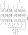
- FIG. 1 shows a modular multilevel converter (MMC) implemented as a variable speed drive (VSD).
- the MMC includes three converter arms 2 1 , 2 2 and 2 3 connected in parallel between first and second direct current (DC) buses 4, 6.
- Each converter arm is divided into an upper arm and a lower arm.
- Each upper arm includes n series-connected submodules 8 1 , 8 2 , ..., 8 n and each lower arm includes n series-connected submodules 10 1 , 10 2 , ..., 10 n , where n is any suitable integer.
- the connection between the upper arm and the lower arm of the first converter arm 2 1 defines a first alternating current (AC) bus 12.
- the connection between the upper arm and the lower arm of the second converter arm 2 2 defines a second AC bus 14.
- the connection between the upper arm and the lower arm of the third converter arm 2 3 defines a third AC bus 16.
- the first, second and third AC buses 12, 14 and 16 can be connected to a three-phase AC load or a three-phase AC supply.
- the first and second DC buses 4 and 6 can be connected to a DC load or a DC supply and can include a DC link with one or more energy storage devices (e.g., capacitor).
- each converter arm includes a redundant submodule 8 1 and (n-1) active submodules 8 2 , ..., 8 n .
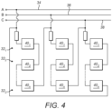
- Each converter arm 32 1 , 32 2 and 32 3 includes a redundant submodule 40 1 and (n-1) active submodules 40 2 , ..., 40 n .
- Submodules 52 2 , ..., 52 n are active submodules.
Landscapes
- Engineering & Computer Science (AREA)
- Power Engineering (AREA)
- Physics & Mathematics (AREA)
- Electromagnetism (AREA)
- Inverter Devices (AREA)
- Electric Propulsion And Braking For Vehicles (AREA)
Priority Applications (1)
| Application Number | Priority Date | Filing Date | Title |
|---|---|---|---|
| EP25154973.9A EP4525017A3 (de) | 2020-05-22 | 2020-05-22 | Modulare mehrstufige wandler |
Applications Claiming Priority (2)
| Application Number | Priority Date | Filing Date | Title |
|---|---|---|---|
| EP20175977.6A EP3913781B1 (de) | 2020-05-22 | 2020-05-22 | Modulare mehrstufige wandler |
| EP25154973.9A EP4525017A3 (de) | 2020-05-22 | 2020-05-22 | Modulare mehrstufige wandler |
Related Parent Applications (2)
| Application Number | Title | Priority Date | Filing Date |
|---|---|---|---|
| EP20175977.6A Division-Into EP3913781B1 (de) | 2020-05-22 | 2020-05-22 | Modulare mehrstufige wandler |
| EP20175977.6A Division EP3913781B1 (de) | 2020-05-22 | 2020-05-22 | Modulare mehrstufige wandler |
Publications (2)
| Publication Number | Publication Date |
|---|---|
| EP4525017A2 true EP4525017A2 (de) | 2025-03-19 |
| EP4525017A3 EP4525017A3 (de) | 2025-08-27 |
Family
ID=70804483
Family Applications (2)
| Application Number | Title | Priority Date | Filing Date |
|---|---|---|---|
| EP25154973.9A Pending EP4525017A3 (de) | 2020-05-22 | 2020-05-22 | Modulare mehrstufige wandler |
| EP20175977.6A Active EP3913781B1 (de) | 2020-05-22 | 2020-05-22 | Modulare mehrstufige wandler |
Family Applications After (1)
| Application Number | Title | Priority Date | Filing Date |
|---|---|---|---|
| EP20175977.6A Active EP3913781B1 (de) | 2020-05-22 | 2020-05-22 | Modulare mehrstufige wandler |
Country Status (1)
| Country | Link |
|---|---|
| EP (2) | EP4525017A3 (de) |
Families Citing this family (1)
| Publication number | Priority date | Publication date | Assignee | Title |
|---|---|---|---|---|
| EP4572120A1 (de) * | 2023-12-15 | 2025-06-18 | Rimac Technology LLC | Mehrstufiger wandler und verfahren zur steuerung eines mehrstufigen wandlers |
Citations (2)
| Publication number | Priority date | Publication date | Assignee | Title |
|---|---|---|---|---|
| US20080137253A1 (en) | 2003-08-08 | 2008-06-12 | George Terry A | Circuit Interruption Device |
| US20180277325A1 (en) | 2015-09-10 | 2018-09-27 | Mersen France Sb Sas | Protective device for an electrical circuit, electrical circuit provided with such a device and method for protecting such an electrical circuit |
Family Cites Families (8)
| Publication number | Priority date | Publication date | Assignee | Title |
|---|---|---|---|---|
| CN209046521U (zh) * | 2015-10-09 | 2019-06-28 | 西门子股份公司 | 多电平转换器和具有多电平转换器的装置 |
| EP3157034B1 (de) * | 2015-10-13 | 2018-03-21 | General Electric Technology GmbH | Mechatronische leistungsschaltervorrichtung |
| KR20170090911A (ko) * | 2016-01-29 | 2017-08-08 | 엘에스산전 주식회사 | 서브 모듈 제어장치 |
| US10312040B2 (en) * | 2016-05-11 | 2019-06-04 | Eaton Intelligent Power Limited | Modular circuit protection systems and methods |
| CN105895458A (zh) * | 2016-05-26 | 2016-08-24 | 许继电气股份有限公司 | 直流断路器及其转移支路用功率组件 |
| DE102016116128A1 (de) * | 2016-08-30 | 2018-03-01 | Dr. Ing. H.C. F. Porsche Aktiengesellschaft | Vorrichtung und Verfahren zur Integration eines elektrischen Elements in eine elektrische Schaltung unter Last |
| CN206117539U (zh) * | 2016-10-26 | 2017-04-19 | 中国石油大学(华东) | 一种具有自保护功能的电流源型模块化多电平变换器 |
| CN111026082B (zh) * | 2019-12-11 | 2021-05-04 | 全球能源互联网研究院有限公司 | 一种换流链及其阀基控制器试验电路及试验方法 |
-
2020
- 2020-05-22 EP EP25154973.9A patent/EP4525017A3/de active Pending
- 2020-05-22 EP EP20175977.6A patent/EP3913781B1/de active Active
Patent Citations (2)
| Publication number | Priority date | Publication date | Assignee | Title |
|---|---|---|---|---|
| US20080137253A1 (en) | 2003-08-08 | 2008-06-12 | George Terry A | Circuit Interruption Device |
| US20180277325A1 (en) | 2015-09-10 | 2018-09-27 | Mersen France Sb Sas | Protective device for an electrical circuit, electrical circuit provided with such a device and method for protecting such an electrical circuit |
Also Published As
| Publication number | Publication date |
|---|---|
| EP3913781B1 (de) | 2025-04-23 |
| EP4525017A3 (de) | 2025-08-27 |
| EP3913781A1 (de) | 2021-11-24 |
Similar Documents
| Publication | Publication Date | Title |
|---|---|---|
| Zhang et al. | Review of modular multilevel converter based multi-terminal HVDC systems for offshore wind power transmission | |
| EP0951126B1 (de) | Kompensationsvorrichtung und Leistungsübertragungssystem damit | |
| CN104022674A (zh) | 转换器 | |
| US12525870B2 (en) | Fault current reduction for power converter systems | |
| KR101801780B1 (ko) | 고효율 전력 변환 시스템 | |
| AU2020306347B2 (en) | Arc furnace power supply with converter circuit | |
| Dijkhuizen et al. | Fault tolerant operation of power converter with cascaded cells | |
| EP3544163B1 (de) | Wandler | |
| KR102176029B1 (ko) | Dc 고장 전류의 초고속 차단을 위한 장치 및 이의 제어 방법 | |
| KR102639213B1 (ko) | 전력계통 안정도 개선 장치 | |
| US20210359617A1 (en) | Electrical assembly | |
| EP3913781B1 (de) | Modulare mehrstufige wandler | |
| WO2018041338A1 (en) | Short-circuit protection of a converter cell auxiliary power supply in a modular multi-cell converter | |
| US12068679B2 (en) | Power conversion device preventing overcurrent at the time of starting | |
| EP3829047A1 (de) | Wandler | |
| EP3614543A1 (de) | Schaltventil | |
| Norrga et al. | Power Electronics for HVDC Grids–an Overview | |
| Mwinyiwiwa et al. | Multilevel converters as series VAR compensators | |
| Kumar et al. | A review of modular multilevel converters and its applications | |
| JP7787407B2 (ja) | 双方向型電源システム | |
| JP7760106B2 (ja) | 無停電電源システム | |
| JP7606113B2 (ja) | 電源システム及び電源システムの制御方法 | |
| EP4402786B1 (de) | Laden eines modularen multilevelumrichters | |
| US20230402935A1 (en) | Electrical assembly | |
| CN119051424A (zh) | 一种抑制模块化多电平换流器冲击电流的启动方法 |
Legal Events
| Date | Code | Title | Description |
|---|---|---|---|
| PUAI | Public reference made under article 153(3) epc to a published international application that has entered the european phase |
Free format text: ORIGINAL CODE: 0009012 |
|
| STAA | Information on the status of an ep patent application or granted ep patent |
Free format text: STATUS: THE APPLICATION HAS BEEN PUBLISHED |
|
| AC | Divisional application: reference to earlier application |
Ref document number: 3913781 Country of ref document: EP Kind code of ref document: P |
|
| AK | Designated contracting states |
Kind code of ref document: A2 Designated state(s): AL AT BE BG CH CY CZ DE DK EE ES FI FR GB GR HR HU IE IS IT LI LT LU LV MC MK MT NL NO PL PT RO RS SE SI SK SM TR |
|
| REG | Reference to a national code |
Ref country code: DE Ref legal event code: R079 Free format text: PREVIOUS MAIN CLASS: H01H0071140000 Ipc: H02M0001320000 |
|
| PUAL | Search report despatched |
Free format text: ORIGINAL CODE: 0009013 |
|
| AK | Designated contracting states |
Kind code of ref document: A3 Designated state(s): AL AT BE BG CH CY CZ DE DK EE ES FI FR GB GR HR HU IE IS IT LI LT LU LV MC MK MT NL NO PL PT RO RS SE SI SK SM TR |
|
| RIC1 | Information provided on ipc code assigned before grant |
Ipc: H02H 7/122 20060101ALI20250512BHEP Ipc: H01H 7/14 20060101ALI20250512BHEP Ipc: H02H 9/02 20060101ALI20250512BHEP Ipc: H02M 7/483 20070101ALI20250512BHEP Ipc: H02M 1/32 20070101AFI20250512BHEP |
|
| PUAF | Information related to the publication of a search report (a3 document) modified or deleted |
Free format text: ORIGINAL CODE: 0009199SEPU |
|
| D17D | Deferred search report published (deleted) | ||
| RIC1 | Information provided on ipc code assigned before grant |
Ipc: H02M 1/32 20070101AFI20250616BHEP Ipc: H02M 7/483 20070101ALI20250616BHEP Ipc: H02H 9/02 20060101ALI20250616BHEP Ipc: H01H 7/14 20060101ALI20250616BHEP Ipc: H02H 7/122 20060101ALI20250616BHEP |
|
| PUAL | Search report despatched |
Free format text: ORIGINAL CODE: 0009013 |
|
| AK | Designated contracting states |
Kind code of ref document: A3 Designated state(s): AL AT BE BG CH CY CZ DE DK EE ES FI FR GB GR HR HU IE IS IT LI LT LU LV MC MK MT NL NO PL PT RO RS SE SI SK SM TR |
|
| STAA | Information on the status of an ep patent application or granted ep patent |
Free format text: STATUS: REQUEST FOR EXAMINATION WAS MADE |
|
| 17P | Request for examination filed |
Effective date: 20260227 |