EP4525009A1 - High voltage device - Google Patents
High voltage device Download PDFInfo
- Publication number
- EP4525009A1 EP4525009A1 EP23197606.9A EP23197606A EP4525009A1 EP 4525009 A1 EP4525009 A1 EP 4525009A1 EP 23197606 A EP23197606 A EP 23197606A EP 4525009 A1 EP4525009 A1 EP 4525009A1
- Authority
- EP
- European Patent Office
- Prior art keywords
- micro
- voltage device
- architectured
- architectured material
- winding
- Prior art date
- Legal status (The legal status is an assumption and is not a legal conclusion. Google has not performed a legal analysis and makes no representation as to the accuracy of the status listed.)
- Withdrawn
Links
Images




Classifications
-
- H—ELECTRICITY
- H01—ELECTRIC ELEMENTS
- H01F—MAGNETS; INDUCTANCES; TRANSFORMERS; SELECTION OF MATERIALS FOR THEIR MAGNETIC PROPERTIES
- H01F5/00—Coils
- H01F5/06—Insulation of windings
-
- H—ELECTRICITY
- H01—ELECTRIC ELEMENTS
- H01F—MAGNETS; INDUCTANCES; TRANSFORMERS; SELECTION OF MATERIALS FOR THEIR MAGNETIC PROPERTIES
- H01F27/00—Details of transformers or inductances, in general
- H01F27/08—Cooling; Ventilating
- H01F27/10—Liquid cooling
- H01F27/12—Oil cooling
-
- H—ELECTRICITY
- H01—ELECTRIC ELEMENTS
- H01F—MAGNETS; INDUCTANCES; TRANSFORMERS; SELECTION OF MATERIALS FOR THEIR MAGNETIC PROPERTIES
- H01F27/00—Details of transformers or inductances, in general
- H01F27/28—Coils; Windings; Conductive connections
- H01F27/32—Insulating of coils, windings, or parts thereof
- H01F27/324—Insulation between coil and core, between different winding sections, around the coil; Other insulation structures
-
- H—ELECTRICITY
- H01—ELECTRIC ELEMENTS
- H01F—MAGNETS; INDUCTANCES; TRANSFORMERS; SELECTION OF MATERIALS FOR THEIR MAGNETIC PROPERTIES
- H01F27/00—Details of transformers or inductances, in general
- H01F27/33—Arrangements for noise damping
Definitions
- the present disclosure relates to a high-voltage device, particularly to a high-voltage power device.
- One object to be achieved is to provide a high-voltage device with improved properties, e.g. a reduced noise radiation.
- the high-voltage device comprises at least one winding and at least one structure adjacent to the at least one winding.
- the structure comprises a micro-architectured material.
- micro-architectured materials are materials which can be tailored to desired properties, like the capability of absorbing vibro-acoustic energy. Also the thermal and electric insulation properties can be tailored. The usage of micro-architectured materials in high-voltage devices provides many possibilities for improving the properties of the high-voltage device.
- a high voltage device is a device in which, during operation, voltage difference of more than 1000 V or more than 1500 V between electrical components of the device appear. For example, during operation, electrical currents of more than 100 A or more than 1000 A flow in the high-voltage device.
- the high voltage device comprises one or more windings. All features disclosed herein for one winding are also disclosed for the other winding(s).
- the winding may be wound around a core of metal, e.g. steel.
- the high-voltage device may be transformer, particularly a power transformer, or a reactor.
- the at least two windings may be galvanically insulated from each other.
- the high-voltage device may comprise a primary winding, a secondary winding and a tertiary winding.
- the at least two windings are, for example, wound around a common core.
- the windings may be arranged adjacent to each other, i.e. wound around parallel axes which are spaced from each other. Alternatively, the windings may be wound concentrically around the same axis.
- the structure which is adjacent to the at least one winding comprises or consists of micro-architectured material.
- the structure may be arranged between two windings or may be arranged inside of the at least one winding.
- the high-voltage device may comprise two or more structures comprising a micro-architectured material adjacent to the at least one winding. All features disclosed for one structure are also disclosed for all other structures of the high-voltage device.
- the at least one structure may be electrically insulated from the at least one winding.
- the structure is spaced from the at least one winding.
- Micro-architectured materials are also known as metamaterials or MAM. They are a class of porous multiscale materials formed by the periodic or semi-periodic assembly of one or more unit-cells or representative volume elements (RVE) in the design space.
- the unit cell or RVE may have dimensions in the micrometer to millimeter range.
- Micro-architectured materials can be designed isotropically or anisotropically. For example, micro-architectured materials provide the possibility to tailor the Poisson's ratio and/or the Young's modulus through the design of the micro-architectured material.
- the micro-architectured material is designed for damping noise generated in the high-voltage device during operation. This can be achieved by tailoring the Young's modulus and/or the Poisson's ratio of the micro-architectured material.
- the micro-architectured material may be designed to mitigate the effect of radial and/or axial winding forces and/or may be fine-tuned for force overtones and/or the eigenfrequencies of the high-voltage device.
- the micro-architectured material has a Young's modulus between 3 MPa inclusive and 200 GPa inclusive.
- this Young's modulus is the average Young's modulus averaged over all directions or is the minimum Young's modulus or the maximum Young's modulus.
- the micro-architectured material has a negative Poisson's ratio or a Poisson's ratio of zero. These materials have unique properties and functionalities that are interesting for a wide range of potential applications.
- the micro-architectured material may have one single value of the Poisson's ratio or it may vary depending on the direction of compression and or depending on the location of the material in the structure.
- the micro-architectured material may be shape-shifting or shape-morphing.
- the hexagonal (with positive or negative angle) and chiral unit cells are some examples of the unit cell geometries which can be used for the design of micro-architectured materials with tunable material properties, like the Poisson's ratio.
- tunable material properties like the Poisson's ratio.
- the micro-architectured material is formed by an additive manufacturing process, for example by 3D-printing.
- the skilled person is able to detect whether a structure was formed by additive manufacturing.
- the micro-architectured material is formed in one piece or integrally, i.e. without internal interfaces.
- the micro-architectured material has an anisotropic structure.
- the micro-architectured material may have a different structure in radial direction than in circumferential and/or axial direction.
- Anisotropic structures can provide particular beneficial effects in view of noise damping.
- the micro-architectured material has a porous structure.
- the porosity is between 10% and 90% inclusive.
- porosity is defined as the cavity volume (volume of the pores) over the total volume.
- the structure is at least partially arranged in oil.
- the micro-architectured material is arranged in the oil.
- the oil is used for cooling and/or electrical insulation in the high-voltage device.
- the structure is embedded in the oil, i.e. is in contact with the oil.
- the pores of the micro-architectured material are formed such that the micro-architectured material is permeable for the oil.
- the micro-architectured material is impregnated with the oil.
- the micro-architectured material is at least partially formed of cellulose. Additionally or alternatively, the micro-architectured material may be at least partially formed of polymer and/or metal.
- the structure is a barrier between two windings of the high-voltage device. Additionally or alternatively, the structure is a barrier between the at least one winding and a housing of the high-voltage device.
- the housing of the high-voltage device surrounds the winding(s), for example.
- the housing may be a tank or tank wall, respectively.
- the barrier may be formed as a plate or as a cylinder shell.
- the structure is a spacer or a spacer-block for one of the winding.
- Spacers are used to support and separate individual turns of a winding from each other in axial direction and/or to support the turns in radial direction.
- Spacer-blocks are in particular there to maintain certain distance between winding ends and the core.
- the structure is an electrical insulation of a winding.
- the structure is a cover around the turns of a winding.
- the structure is spaced from the windings.
- the structure or at least the micro-architectured material thereof is not in contact with any of the windings.
- the gap between the structure and the windings may at least be partially filled with oil.
- the micro-architectured material has a TPMS structure.
- TPMS triply periodic minimal surfaces. This is a non-intersecting 3D surface characterized by a zero value of mean curvature at each point.
- the micro-architectured material has an octet structure.
- a unit cell or the RVE of the micro-architectured material has an octet structure.
- the micro-architectured material or the unit cell / RVE has a tetrakaidekahedron or Gurtner-Durand structure or an irregular tetrahedron structure or a cube structure or a diamond structure or a Kelvin structure or a rhombicuboctahedron structure or a double-pyramid dodecahedron structure.
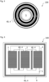
- Figure 1 shows a first exemplary embodiment of a high-voltage device 100, namely a power transformer 100.
- the high-voltage device 100 comprises a housing 6 or tank 6, respectively, in which three windings 1, 2, 3 are arranged.
- the windings 1, 2, 3 are wound around a common core 5.
- the tank 6 is filled with oil.
- a barrier 40 of a micro-architectured material 4 is arranged between the tank 6, i.e. the tank wall, and the windings 1, 2, 3.
- the barrier 40 of the micro-architectured material 4 is arranged in the oil and impregnated with the oil.
- the micro-architectured material 4 comprises pores to enable oil to penetrate the micro-architectured material 4.
- the micro-architectured material is produced by an additive manufacturing process, like 3D-printing. It may comprise or consist of polymer and/or cellulose and/or metal.
- the micro-architectured material 4 is designed such that the barrier 40 damps the noise generated in the high-voltage device 100 during operation, i.e. absorbs vibrations.
- the barrier 40 forms a housing surrounding the windings 1, 2, 3.
- the barrier 40 is spaced from each of the windings 1, 2, 3 such that it does not adjoin any of the metallic parts of the windings 1, 2, 3.
- the barrier 40 is galvanically isolated from the windings 1, 2, 3. This allows to form the micro-architectured material at least partially from metal.
- Figure 2 shows a detailed view of a winding 1, 2, 3 as used, for example, in the transformer 100 of figure 1 .
- the winding 1, 2, 3 comprises a plurality of turns 10 wound around the core and radially spaced from the core by spacer-blocks 11, 41.
- Some spacer-blocks 41 are formed of the micro-architectured material 4.
- the micro-architectured material 4 may be impregnated with the oil of the high-voltage device and/or may serve as a noise damping element of the high-voltage device 100.
- Figure 3 shows a further exemplary embodiment of a high-voltage device 100 with all the windings 1, 2 arranged concentrically.
- Cylindrically shaped barriers 40 of the micro-architectured material 4 are arranged in radial direction between the two windings 1, 2 and between the inner winding 1 and the core 5.
- Another cylindrically shaped barrier 40 is formed around the outer winding 2.
- the barriers 40 may be arranged in the oil and are spaced from the windings 1, 2.
- the micro-architectured material 4 of the barriers 40 may be designed for damping noise generated in the high-voltage device 100.
- the exemplary embodiment of a high-voltage device of figure 4 is based on the one of figure 1 . Additionally, plate-shaped barriers 40 of micro-architectured material 4 are arranged between each two adjacent windings 1, 2, 3. These plate-shape barriers 40 are again arranged in the oil of the high-voltage device 100 and are designed for noise damping.
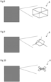
- Figure 5 shows a first exemplary embodiment of a micro-architectured material 4 with a macroscopic piece of the micro-architectured material on the left side and a detailed view of a lattice representative volume element (RVE) or unit cell of the micro-architectured material on the right side.
- RVE lattice representative volume element
- the RVE has a cubic octet structure.
- the individual struts of the shown RVE may be cylindrical with radius and length between 10 um and 1000 ⁇ m, for example.
- the RVE has a tetrakaidekahedron or Gurtner-Durand (isotropic) structure.
- the RVE has an irregular tetrahedron (trigonal symmetry) structure.
- the RVE has a cube (cubic symmetry) structure.
- the RVE has a diamond (cubic symmetry) structure.
- the RVE has a Kelvin (cubic symmetry) structure.
- the RVE has a rhombicuboctahedron (tetragonal symmetry) structure.
- the RVE has a double-pyramid dodecahedron (transverse isotropy) structure.
- the micro-architectured material has a negative Poisson's ratio.
- the micro-architectured material has a Poisson's ratio of zero.
- the micro-architectured material has a positive Poisson's ratio.
- Figures 16 and 17 show exemplary embodiments of micro-architectured materials 4 with a TPMS structure, i.e. a Gyroid structure ( figure 16 ) and a Schwarz P structure ( figure 17 ). These structures are extracted from the paper " On hybrid cellular materials based on triply periodic minimal surfaces with extreme mechanical properties", Chen et al, Materials and Design, 2019, DOI: 10.1016/j.matdes.2019.108109 .
- Each of the materials of figures 5 to 17 can be used as a micro-architectured material for the high-voltage devices of figures 1 to 4 .
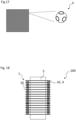
- Figure 18 shows a further exemplary embodiment of the high-voltage device 100.
- the high voltage device could be a power transformer or a power reactor.
- the turns 10 of the winding 1 are axially spaced from each other with the help of spacers 42.
- the spacers 42 are formed of a micro-architectured material 4, e.g. of one according to figures 5 to 17 .
Landscapes
- Engineering & Computer Science (AREA)
- Power Engineering (AREA)
- Coils Of Transformers For General Uses (AREA)
- Transformer Cooling (AREA)
Abstract
According to an embodiment, the high-voltage device (100) comprises at least one winding (1, 2, 3) and at least one structure (40, 41, 42) adjacent to the at least one winding. The structure comprises a micro-architectured material (4).
Description
- The present disclosure relates to a high-voltage device, particularly to a high-voltage power device.
- One object to be achieved is to provide a high-voltage device with improved properties, e.g. a reduced noise radiation.
- According to an embodiment, the high-voltage device comprises at least one winding and at least one structure adjacent to the at least one winding. The structure comprises a micro-architectured material.
- During operation of a high-voltage device with a winding, considerable forces develop, e.g. due to magnetostriction and core resonances. Also the winding experiences strong radial and axial forces due to the high magnetic fields involved. This leads to noise production. The present invention is, inter alia, based on the idea to use one or more micro-architectured materials in a high-voltage device. Micro-architectured materials are materials which can be tailored to desired properties, like the capability of absorbing vibro-acoustic energy. Also the thermal and electric insulation properties can be tailored. The usage of micro-architectured materials in high-voltage devices provides many possibilities for improving the properties of the high-voltage device.
- A high voltage device is a device in which, during operation, voltage difference of more than 1000 V or more than 1500 V between electrical components of the device appear. For example, during operation, electrical currents of more than 100 A or more than 1000 A flow in the high-voltage device.
- The high voltage device comprises one or more windings. All features disclosed herein for one winding are also disclosed for the other winding(s). The winding may be wound around a core of metal, e.g. steel. The high-voltage device may be transformer, particularly a power transformer, or a reactor.
- In case of two or more windings, the at least two windings may be galvanically insulated from each other. The high-voltage device may comprise a primary winding, a secondary winding and a tertiary winding. The at least two windings are, for example, wound around a common core. The windings may be arranged adjacent to each other, i.e. wound around parallel axes which are spaced from each other. Alternatively, the windings may be wound concentrically around the same axis.
- The structure which is adjacent to the at least one winding comprises or consists of micro-architectured material. The structure may be arranged between two windings or may be arranged inside of the at least one winding. The high-voltage device may comprise two or more structures comprising a micro-architectured material adjacent to the at least one winding. All features disclosed for one structure are also disclosed for all other structures of the high-voltage device.
- For example, the at least one structure may be electrically insulated from the at least one winding. Particularly, the structure is spaced from the at least one winding.
- Micro-architectured materials are also known as metamaterials or MAM. They are a class of porous multiscale materials formed by the periodic or semi-periodic assembly of one or more unit-cells or representative volume elements (RVE) in the design space. The unit cell or RVE may have dimensions in the micrometer to millimeter range. Micro-architectured materials can be designed isotropically or anisotropically. For example, micro-architectured materials provide the possibility to tailor the Poisson's ratio and/or the Young's modulus through the design of the micro-architectured material.
- According to a further embodiment, the micro-architectured material is designed for damping noise generated in the high-voltage device during operation. This can be achieved by tailoring the Young's modulus and/or the Poisson's ratio of the micro-architectured material. Particularly, the micro-architectured material may be designed to mitigate the effect of radial and/or axial winding forces and/or may be fine-tuned for force overtones and/or the eigenfrequencies of the high-voltage device.
- According to a further embodiment, the micro-architectured material has a Young's modulus between 3 MPa inclusive and 200 GPa inclusive. For example, in case of an anisotropic Young's modulus, this Young's modulus is the average Young's modulus averaged over all directions or is the minimum Young's modulus or the maximum Young's modulus.
- According to a further embodiment, the micro-architectured material has a negative Poisson's ratio or a Poisson's ratio of zero. These materials have unique properties and functionalities that are interesting for a wide range of potential applications. The micro-architectured material may have one single value of the Poisson's ratio or it may vary depending on the direction of compression and or depending on the location of the material in the structure. The micro-architectured material may be shape-shifting or shape-morphing.
- The hexagonal (with positive or negative angle) and chiral unit cells are some examples of the unit cell geometries which can be used for the design of micro-architectured materials with tunable material properties, like the Poisson's ratio. Thus, already by the design of the unit cell's geometry, one can reach a broad range of elastic properties or even extend this range through random integration of unit cells in the design space of the lattice structures, which allows for targeting very specific combinations of mechanical properties and/or advanced functionalities.
- According to a further embodiment, the micro-architectured material is formed by an additive manufacturing process, for example by 3D-printing. The skilled person is able to detect whether a structure was formed by additive manufacturing. For example, when using 3D printing, the micro-architectured material is formed in one piece or integrally, i.e. without internal interfaces.
- According to a further embodiment, the micro-architectured material has an anisotropic structure. Particular, with respect to one of the windings, the micro-architectured material may have a different structure in radial direction than in circumferential and/or axial direction. Anisotropic structures can provide particular beneficial effects in view of noise damping.
- According to a further embodiment, the micro-architectured material has a porous structure. For example, the porosity is between 10% and 90% inclusive. Thereby, "porosity" is defined as the cavity volume (volume of the pores) over the total volume.
- According to a further embodiment, the structure is at least partially arranged in oil. Particularly, the micro-architectured material is arranged in the oil. The oil is used for cooling and/or electrical insulation in the high-voltage device. For example, the structure is embedded in the oil, i.e. is in contact with the oil.
- According to a further embodiment, the pores of the micro-architectured material are formed such that the micro-architectured material is permeable for the oil. For example, the micro-architectured material is impregnated with the oil.
- According to a further embodiment, the micro-architectured material is at least partially formed of cellulose. Additionally or alternatively, the micro-architectured material may be at least partially formed of polymer and/or metal.
- According to a further embodiment, the structure is a barrier between two windings of the high-voltage device. Additionally or alternatively, the structure is a barrier between the at least one winding and a housing of the high-voltage device. The housing of the high-voltage device surrounds the winding(s), for example. The housing may be a tank or tank wall, respectively. Especially, the barrier may be formed as a plate or as a cylinder shell.
- According to a further embodiment, the structure is a spacer or a spacer-block for one of the winding. Spacers are used to support and separate individual turns of a winding from each other in axial direction and/or to support the turns in radial direction. Spacer-blocks are in particular there to maintain certain distance between winding ends and the core.
- According to a further embodiment, the structure is an electrical insulation of a winding. For example, the structure is a cover around the turns of a winding.
- According to a further embodiment, the structure is spaced from the windings. Particularly, the structure or at least the micro-architectured material thereof is not in contact with any of the windings. The gap between the structure and the windings may at least be partially filled with oil.
- According to a further embodiment, the micro-architectured material has a TPMS structure. "TPMS" stands for triply periodic minimal surfaces. This is a non-intersecting 3D surface characterized by a zero value of mean curvature at each point.
- According to a further embodiment, the micro-architectured material has an octet structure. This means that a unit cell or the RVE of the micro-architectured material has an octet structure. Alternatively, the micro-architectured material or the unit cell / RVE has a tetrakaidekahedron or Gurtner-Durand structure or an irregular tetrahedron structure or a cube structure or a diamond structure or a Kelvin structure or a rhombicuboctahedron structure or a double-pyramid dodecahedron structure.
- Hereinafter, the high-voltage device will be explained in more detail with reference to the drawings on the basis of exemplary embodiments. The accompanying figures are included to provide a further understanding. In the figures, elements of the same structure and/or functionality may be referenced by the same reference signs. It is to be understood that the embodiments shown in the figures are illustrative representations and are not necessarily drawn to scale. In so far as elements or components correspond to one another in terms of their function in different figures, the description thereof is not repeated for each of the following figures. For the sake of clarity, elements might not appear with corresponding reference symbols in all figures.
-
Figures 1 ,3 and 4 show different exemplary embodiments of the high-voltage device, -
Figure 2 shows an exemplary embodiment of the winding of a high-voltage device, -
Figures 5 to 17 show different exemplary embodiments of the micro-architectured material, -
Figure 18 shows a further exemplary embodiment of the high-voltage device. -
Figure 1 shows a first exemplary embodiment of a high-voltage device 100, namely apower transformer 100. The high-voltage device 100 comprises ahousing 6 ortank 6, respectively, in which threewindings windings common core 5. - For electrical insulation and cooling purposes, the
tank 6 is filled with oil. A barrier 40 of amicro-architectured material 4 is arranged between thetank 6, i.e. the tank wall, and thewindings micro-architectured material 4 is arranged in the oil and impregnated with the oil. Particularly, themicro-architectured material 4 comprises pores to enable oil to penetrate themicro-architectured material 4. By way of example, the micro-architectured material is produced by an additive manufacturing process, like 3D-printing. It may comprise or consist of polymer and/or cellulose and/or metal. Themicro-architectured material 4 is designed such that the barrier 40 damps the noise generated in the high-voltage device 100 during operation, i.e. absorbs vibrations. - As can be seen in
figure 1 , the barrier 40 forms a housing surrounding thewindings windings windings windings -
Figure 2 shows a detailed view of a winding 1, 2, 3 as used, for example, in thetransformer 100 offigure 1 . The winding 1, 2, 3 comprises a plurality ofturns 10 wound around the core and radially spaced from the core by spacer-blocks 11, 41. Some spacer-blocks 41 are formed of themicro-architectured material 4. Also here, themicro-architectured material 4 may be impregnated with the oil of the high-voltage device and/or may serve as a noise damping element of the high-voltage device 100. -
Figure 3 shows a further exemplary embodiment of a high-voltage device 100 with all thewindings micro-architectured material 4 are arranged in radial direction between the twowindings core 5. Another cylindrically shaped barrier 40 is formed around the outer winding 2. - Also in case of
figure 3 , the barriers 40 may be arranged in the oil and are spaced from thewindings micro-architectured material 4 of the barriers 40 may be designed for damping noise generated in the high-voltage device 100. - The exemplary embodiment of a high-voltage device of
figure 4 is based on the one offigure 1 . Additionally, plate-shaped barriers 40 ofmicro-architectured material 4 are arranged between each twoadjacent windings voltage device 100 and are designed for noise damping. -
Figure 5 shows a first exemplary embodiment of amicro-architectured material 4 with a macroscopic piece of the micro-architectured material on the left side and a detailed view of a lattice representative volume element (RVE) or unit cell of the micro-architectured material on the right side. Here, the RVE has a cubic octet structure. The individual struts of the shown RVE may be cylindrical with radius and length between 10 um and 1000 µm, for example. - In the exemplary embodiment of
figure 6 , the RVE has a tetrakaidekahedron or Gurtner-Durand (isotropic) structure. - In the exemplary embodiment of
figure 7 , the RVE has an irregular tetrahedron (trigonal symmetry) structure. - In the exemplary embodiment of
figure 8 , the RVE has a cube (cubic symmetry) structure. - In the exemplary embodiment of
figure 9 , the RVE has a diamond (cubic symmetry) structure. - In the exemplary embodiment of
figure 10 , the RVE has a Kelvin (cubic symmetry) structure. - In the exemplary embodiment of
figure 11 , the RVE has a rhombicuboctahedron (tetragonal symmetry) structure. - In the exemplary embodiment of
figure 12 , the RVE has a double-pyramid dodecahedron (transverse isotropy) structure. - In the exemplary embodiment of
figure 13 , the micro-architectured material has a negative Poisson's ratio. - In the exemplary embodiment of
figure 14 , the micro-architectured material has a Poisson's ratio of zero. - In the exemplary embodiment of
figure 15 , the micro-architectured material has a positive Poisson's ratio. -
Figures 16 and17 show exemplary embodiments ofmicro-architectured materials 4 with a TPMS structure, i.e. a Gyroid structure (figure 16 ) and a Schwarz P structure (figure 17 ). These structures are extracted from the paper "On hybrid cellular materials based on triply periodic minimal surfaces with extreme mechanical properties", Chen et al, Materials and Design, 2019, DOI: 10.1016/j.matdes.2019.108109. - Each of the materials of
figures 5 to 17 can be used as a micro-architectured material for the high-voltage devices offigures 1 to 4 . -
Figure 18 shows a further exemplary embodiment of the high-voltage device 100. In this case, the high voltage device could be a power transformer or a power reactor. The turns 10 of the winding 1 are axially spaced from each other with the help of spacers 42. The spacers 42 are formed of amicro-architectured material 4, e.g. of one according tofigures 5 to 17 . - The embodiments shown in the
Figures 1 to 18 as stated represent exemplary embodiments of the high-voltage device and the micro-architectured material. They do not constitute a complete list of all embodiments according to the high-voltage device and the micro-architectured material. Actual high-voltage devices and micro-architectured materials may vary from the embodiments shown in terms of arrangements and sizes, for example. -
- 1
- winding
- 2
- winding
- 3
- winding
- 4
- micro-architectured material
- 5
- core
- 6
- housing / tank
- 10
- turns
- 11
- spacer block
- 40
- structure / barrier
- 41
- structure / spacer-block
- 42
- structure / spacer
- 100
- high-voltage device
Claims (15)
- High-voltage device (100) comprising- at least one winding (1, 2, 3),- at least one structure (40, 41, 42) adjacent to the at least one winding (1, 2, 3), wherein- the structure (40, 41, 42) comprises a micro-architectured material (4).
- High-voltage device (100) according to claim 1, wherein- the micro-architectured material (4) is designed for damping noise generated in the high-voltage device (100) during operation.
- High-voltage device (100) according to claim 1 or 2, wherein- the micro-architectured material (4) has a Young's modulus between 3 MPa and 200 GPa.
- High-voltage device (100) according to any one of the preceding claims, wherein- the micro-architectured material (4) has a negative Poisson's ratio or a Poisson's ratio of zero.
- High-voltage device (100) according to any one of the preceding claims, wherein- the high voltage device (100) is a transformer or a reactor.
- High-voltage device (100) according to any one of the preceding claims, wherein- the micro-architectured material (4) is formed by an additive manufacturing process.
- High-voltage device (100) according to any one of the preceding claims, wherein- the micro-architectured material (4) has a porous structure.
- High-voltage device (100) according to claim 7, wherein- the structure (40, 41, 42) is at least partially arranged in oil,- the pores of the micro-architectured material (4) are formed such that the micro-architectured material (4) is permeable for the oil.
- High-voltage device (100) according to any one of the preceding claims, wherein- the micro-architectured material (4) is at least partially formed of a polymer.
- High-voltage device (100) according to any one of the preceding claims, wherein- the micro-architectured material (4) is at least partially formed of cellulose.
- High-voltage device (100) according to any of the preceding claims, wherein- the structure (40, 41, 42) is a barrier (40) between two windings (1, 2, 3) and/or a barrier (40) between the at least one winding (1, 2, 3) and a housing (6) of the high-voltage device (100).
- High-voltage device (100) according to any of the preceding claims, wherein- the structure (40, 41, 42) is a spacer (42) or a spacer-block (41) for one of the windings (1, 2, 3).
- High-voltage device (100) according to any one of the preceding claims, wherein- the micro-architectured material (4) has a TPMS structure.
- High-voltage device (100) according to any one of the preceding claims, wherein- the micro-architectured material (4) has an octet structure or a tetrakaidekahedron structure or an tetrahedron structure or a cube structure or a diamond structure or a Kelvin structure or a rhombicuboctahedron structure or a double-pyramid dodecahedron structure.
- High-voltage device (100) according to any one of the preceding claims, wherein- the micro-architectured material (4) is at least partially formed of metal,- the structure (40, 41, 42) is spaced from the at least one winding (1, 2, 3).
Priority Applications (4)
| Application Number | Priority Date | Filing Date | Title |
|---|---|---|---|
| EP23197606.9A EP4525009A1 (en) | 2023-09-15 | 2023-09-15 | High voltage device |
| KR1020267007973A KR20260049315A (en) | 2023-09-15 | 2024-04-22 | High-voltage device |
| CN202480058714.XA CN121866636A (en) | 2023-09-15 | 2024-04-22 | High voltage equipment |
| PCT/EP2024/060923 WO2025056196A1 (en) | 2023-09-15 | 2024-04-22 | High-voltage device |
Applications Claiming Priority (1)
| Application Number | Priority Date | Filing Date | Title |
|---|---|---|---|
| EP23197606.9A EP4525009A1 (en) | 2023-09-15 | 2023-09-15 | High voltage device |
Publications (1)
| Publication Number | Publication Date |
|---|---|
| EP4525009A1 true EP4525009A1 (en) | 2025-03-19 |
Family
ID=88092887
Family Applications (1)
| Application Number | Title | Priority Date | Filing Date |
|---|---|---|---|
| EP23197606.9A Withdrawn EP4525009A1 (en) | 2023-09-15 | 2023-09-15 | High voltage device |
Country Status (4)
| Country | Link |
|---|---|
| EP (1) | EP4525009A1 (en) |
| KR (1) | KR20260049315A (en) |
| CN (1) | CN121866636A (en) |
| WO (1) | WO2025056196A1 (en) |
Citations (4)
| Publication number | Priority date | Publication date | Assignee | Title |
|---|---|---|---|---|
| JP2016006239A (en) * | 2014-06-20 | 2016-01-14 | 株式会社日立製作所 | Electrical insulation paper and stationary induction electric device using the same |
| CN113066463A (en) * | 2021-03-23 | 2021-07-02 | 国网河北省电力有限公司沧州供电分公司 | Sound absorption and insulation structure for controlling sound vibration of transformer oil tank, transformer oil tank and transformer |
| EP3904818A1 (en) * | 2020-04-30 | 2021-11-03 | ABB Power Grids Switzerland AG | Electric arrangement, panel and heat exchanger |
| US11719492B2 (en) * | 2020-04-30 | 2023-08-08 | Hitachi Energy Switzerland Ag | Heat exchanger and electric arrangement comprising heat exchanger |
-
2023
- 2023-09-15 EP EP23197606.9A patent/EP4525009A1/en not_active Withdrawn
-
2024
- 2024-04-22 KR KR1020267007973A patent/KR20260049315A/en active Pending
- 2024-04-22 WO PCT/EP2024/060923 patent/WO2025056196A1/en active Pending
- 2024-04-22 CN CN202480058714.XA patent/CN121866636A/en active Pending
Patent Citations (4)
| Publication number | Priority date | Publication date | Assignee | Title |
|---|---|---|---|---|
| JP2016006239A (en) * | 2014-06-20 | 2016-01-14 | 株式会社日立製作所 | Electrical insulation paper and stationary induction electric device using the same |
| EP3904818A1 (en) * | 2020-04-30 | 2021-11-03 | ABB Power Grids Switzerland AG | Electric arrangement, panel and heat exchanger |
| US11719492B2 (en) * | 2020-04-30 | 2023-08-08 | Hitachi Energy Switzerland Ag | Heat exchanger and electric arrangement comprising heat exchanger |
| CN113066463A (en) * | 2021-03-23 | 2021-07-02 | 国网河北省电力有限公司沧州供电分公司 | Sound absorption and insulation structure for controlling sound vibration of transformer oil tank, transformer oil tank and transformer |
Non-Patent Citations (3)
| Title |
|---|
| CHAO TANG ET AL: "A review on the research progress and future development of nano-modified cellulose insulation paper", IET NANODIELECTRICS, JOHN WILEY & SONS, INC, HOBOKEN, USA, vol. 5, no. 2, 21 December 2021 (2021-12-21), pages 63 - 84, XP006115626, ISSN: 2514-3255, DOI: 10.1049/NDE2.12032 * |
| CHEN ET AL.: "On hybrid cellular materials based on triply periodic minimal surfaces with extreme mechanical properties", MATERIALS AND DESIGN, 2019 |
| SIDDIQUE ZAID B ET AL: "Effect of Graphene Oxide Dispersed Natural Ester Based Insulating Oil on Transformer Solid Insulation", IEEE TRANSACTIONS ON DIELECTRICS AND ELECTRICAL INSULATION, IEEE SERVICE CENTER, PISCATAWAY, NJ, US, vol. 29, no. 2, 8 March 2022 (2022-03-08), pages 378 - 385, XP011907145, ISSN: 1070-9878, [retrieved on 20220308], DOI: 10.1109/TDEI.2022.3157926 * |
Also Published As
| Publication number | Publication date |
|---|---|
| WO2025056196A1 (en) | 2025-03-20 |
| CN121866636A (en) | 2026-04-14 |
| KR20260049315A (en) | 2026-04-13 |
Similar Documents
| Publication | Publication Date | Title |
|---|---|---|
| EP2690767B1 (en) | Vibration power generator | |
| US8647091B2 (en) | Stator compacted in one piece | |
| AU728661B2 (en) | Insulation for a conductor | |
| JP2016066686A (en) | Reactor | |
| WO2017030850A1 (en) | Stator positioner for electrostatic generator electrodes and new electrode design | |
| JP2008186744A (en) | Molded lightning arrester and its manufacture method | |
| US3670276A (en) | Hermetic transformer | |
| US20150084454A1 (en) | Pole unit and stator assembly for a wind turbine generator, and methods of manufacturing the same | |
| WO2025056196A1 (en) | High-voltage device | |
| US7978038B2 (en) | Electromagnetic actuator with variable reluctance | |
| CN209608432U (en) | A kind of motor can be reduced encapsulating winding body heat stress | |
| KR100758067B1 (en) | Electromagnetic actuator, and stirling engine | |
| JP2016033861A (en) | Capacitor bushing and manufacturing method thereof | |
| US3579163A (en) | Liquid-filled transformer with foamed insulation | |
| CN103095050A (en) | Cooling Assembly For Electric Machines | |
| JP3797996B2 (en) | Electromagnetic actuator and Stirling engine | |
| CN109004261B (en) | A battery | |
| JP3758751B2 (en) | Canned motor | |
| EP2423927B1 (en) | An electromagnetic device | |
| CN202424336U (en) | Permanent magnetism motor rotor structure | |
| CN113027988A (en) | Active and passive composite electromagnetic vibration isolation device and design method thereof | |
| CN223401646U (en) | Center tube and battery | |
| EP4586471A1 (en) | Integrated lattice structure in housing for cooling an electric generator | |
| CN118309764B (en) | Longitudinal and transverse decoupling composite metal shock absorber | |
| EP4600981A1 (en) | Transformer spacer, manufacturing method and transformer |
Legal Events
| Date | Code | Title | Description |
|---|---|---|---|
| PUAI | Public reference made under article 153(3) epc to a published international application that has entered the european phase |
Free format text: ORIGINAL CODE: 0009012 |
|
| STAA | Information on the status of an ep patent application or granted ep patent |
Free format text: STATUS: THE APPLICATION HAS BEEN PUBLISHED |
|
| AK | Designated contracting states |
Kind code of ref document: A1 Designated state(s): AL AT BE BG CH CY CZ DE DK EE ES FI FR GB GR HR HU IE IS IT LI LT LU LV MC ME MK MT NL NO PL PT RO RS SE SI SK SM TR |
|
| STAA | Information on the status of an ep patent application or granted ep patent |
Free format text: STATUS: THE APPLICATION IS DEEMED TO BE WITHDRAWN |
|
| 18D | Application deemed to be withdrawn |
Effective date: 20250920 |