EP4524549A1 - Infrared gas analyzer, and infrared gas analysis method - Google Patents
Infrared gas analyzer, and infrared gas analysis method Download PDFInfo
- Publication number
- EP4524549A1 EP4524549A1 EP23803462.3A EP23803462A EP4524549A1 EP 4524549 A1 EP4524549 A1 EP 4524549A1 EP 23803462 A EP23803462 A EP 23803462A EP 4524549 A1 EP4524549 A1 EP 4524549A1
- Authority
- EP
- European Patent Office
- Prior art keywords
- gas
- infrared light
- measurement
- detector
- interference
- Prior art date
- Legal status (The legal status is an assumption and is not a legal conclusion. Google has not performed a legal analysis and makes no representation as to the accuracy of the status listed.)
- Withdrawn
Links
Images

Classifications
-
- G—PHYSICS
- G01—MEASURING; TESTING
- G01N—INVESTIGATING OR ANALYSING MATERIALS BY DETERMINING THEIR CHEMICAL OR PHYSICAL PROPERTIES
- G01N21/00—Investigating or analysing materials by the use of optical means, i.e. using sub-millimetre waves, infrared, visible or ultraviolet light
- G01N21/17—Systems in which incident light is modified in accordance with the properties of the material investigated
- G01N21/25—Colour; Spectral properties, i.e. comparison of effect of material on the light at two or more different wavelengths or wavelength bands
- G01N21/31—Investigating relative effect of material at wavelengths characteristic of specific elements or molecules, e.g. atomic absorption spectrometry
- G01N21/35—Investigating relative effect of material at wavelengths characteristic of specific elements or molecules, e.g. atomic absorption spectrometry using infrared light
- G01N21/3504—Investigating relative effect of material at wavelengths characteristic of specific elements or molecules, e.g. atomic absorption spectrometry using infrared light for analysing gases, e.g. multi-gas analysis
- G01N21/3518—Devices using gas filter correlation techniques; Devices using gas pressure modulation techniques
-
- G—PHYSICS
- G01—MEASURING; TESTING
- G01N—INVESTIGATING OR ANALYSING MATERIALS BY DETERMINING THEIR CHEMICAL OR PHYSICAL PROPERTIES
- G01N21/00—Investigating or analysing materials by the use of optical means, i.e. using sub-millimetre waves, infrared, visible or ultraviolet light
- G01N21/17—Systems in which incident light is modified in accordance with the properties of the material investigated
- G01N21/25—Colour; Spectral properties, i.e. comparison of effect of material on the light at two or more different wavelengths or wavelength bands
- G01N21/31—Investigating relative effect of material at wavelengths characteristic of specific elements or molecules, e.g. atomic absorption spectrometry
- G01N21/35—Investigating relative effect of material at wavelengths characteristic of specific elements or molecules, e.g. atomic absorption spectrometry using infrared light
- G01N21/3504—Investigating relative effect of material at wavelengths characteristic of specific elements or molecules, e.g. atomic absorption spectrometry using infrared light for analysing gases, e.g. multi-gas analysis
-
- G—PHYSICS
- G01—MEASURING; TESTING
- G01N—INVESTIGATING OR ANALYSING MATERIALS BY DETERMINING THEIR CHEMICAL OR PHYSICAL PROPERTIES
- G01N21/00—Investigating or analysing materials by the use of optical means, i.e. using sub-millimetre waves, infrared, visible or ultraviolet light
- G01N21/17—Systems in which incident light is modified in accordance with the properties of the material investigated
- G01N21/25—Colour; Spectral properties, i.e. comparison of effect of material on the light at two or more different wavelengths or wavelength bands
- G01N21/31—Investigating relative effect of material at wavelengths characteristic of specific elements or molecules, e.g. atomic absorption spectrometry
- G01N21/35—Investigating relative effect of material at wavelengths characteristic of specific elements or molecules, e.g. atomic absorption spectrometry using infrared light
- G01N21/3504—Investigating relative effect of material at wavelengths characteristic of specific elements or molecules, e.g. atomic absorption spectrometry using infrared light for analysing gases, e.g. multi-gas analysis
- G01N21/3518—Devices using gas filter correlation techniques; Devices using gas pressure modulation techniques
- G01N2021/3527—Devices using gas filter correlation techniques; Devices using gas pressure modulation techniques and using one filter cell as attenuator
-
- G—PHYSICS
- G01—MEASURING; TESTING
- G01N—INVESTIGATING OR ANALYSING MATERIALS BY DETERMINING THEIR CHEMICAL OR PHYSICAL PROPERTIES
- G01N21/00—Investigating or analysing materials by the use of optical means, i.e. using sub-millimetre waves, infrared, visible or ultraviolet light
- G01N21/17—Systems in which incident light is modified in accordance with the properties of the material investigated
- G01N21/25—Colour; Spectral properties, i.e. comparison of effect of material on the light at two or more different wavelengths or wavelength bands
- G01N21/31—Investigating relative effect of material at wavelengths characteristic of specific elements or molecules, e.g. atomic absorption spectrometry
- G01N21/35—Investigating relative effect of material at wavelengths characteristic of specific elements or molecules, e.g. atomic absorption spectrometry using infrared light
- G01N21/3504—Investigating relative effect of material at wavelengths characteristic of specific elements or molecules, e.g. atomic absorption spectrometry using infrared light for analysing gases, e.g. multi-gas analysis
- G01N2021/3545—Disposition for compensating effect of interfering gases
Definitions
- the present invention relates to an infrared gas analyzer and an infrared gas analysis method.
- N 2 O dinitrogen monoxide
- NDIR analyzers non-dispersive infrared absorption devices
- the infrared absorption wavelength range of carbon monoxide (CO) overlaps the infrared absorption wavelength range of N 2 O, and CO is an interference component of N 2 O in its infrared absorption wavelength range. For this reason, attempts have been made to reduce the interference effects of CO by oxidizing CO in the sample gas to carbon dioxide (CO 2 ) using an oxidation catalyst.
- the oxidation catalyst which oxidizes CO to CO 2 , is a consumable item that requires periodic replacement and other maintenance, resulting in high running costs.
- Patent Document 1 JP 2013-96889 A
- the present invention was developed to solve the above-mentioned problems, and its main object is to reduce running costs by eliminating the need for a catalyst, which is a consumable item.
- An infrared gas analyzer is characterized in comprising: a measurement cell into which sample gas is introduced; an infrared light source that irradiates the measurement cell with infrared light; an infrared light detector that detects infrared light that has passed through the measurement cell; and a gas filter within which a plurality of interference components that interfere with a measurement component in the sample gas are enclosed.
- the infrared gas analyzer configured as such has a gas filter within which a plurality of interference components that interfere with the measurement component in the sample gas are enclosed, so that a catalyst that oxidizes or reduces at least one of the plurality of interference components is no longer necessary and, as a result, running costs can be reduced.
- a plurality of interference components are included in the gas filter, the interference effects of a plurality of interference components on the measurement component can be reduced.
- the gas filter has enclosed within a plurality of interference components that do not react with each other or a plurality of interference components that are in a state of stable equilibrium with each other.
- the measurement component of the infrared gas analyzer of the present invention is preferably dinitrogen monoxide (N 2 O), a type of greenhouse gas that contributes to global warming.
- N 2 O dinitrogen monoxide
- the infrared gas analyzer of the present invention can be suitably used in industrial sectors which necessitate a reduction in negative environmental impacts.
- the infrared absorption wavelength range of carbon dioxide (CO 2 ) and the infrared absorption wavelength range of carbon monoxide (CO) each overlap the infrared absorption wavelength range of measurement component N 2 O.
- CO 2 and CO are interference components of N 2 O.
- the gas filter has enclosed within carbon dioxide (CO 2 ) gas and carbon monoxide (CO) gas.
- the gas filter may be enclosed within the gas filter.
- methane (CH 4 ) is included in high concentrations in the sample gas, interference effects of CH 4 will arise.
- the gas filter also has CH 4 gas enclosed within.
- An infrared gas analysis method is characterized as being an infrared gas analysis method of analyzing a measurement component in a sample gas by irradiating a measurement cell into which the sample gas has been introduced with infrared light and detecting the infrared light that has passed through the measurement cell with an infrared light detector, wherein interference effects of a plurality of interference components on the measurement component are reduced by using a gas filter within which a plurality of the interference components that interfere with the measurement component are enclosed.
- the arithmetic unit changes or corrects the weighting coefficient based on the concentration of the interference component.
- an infrared gas analyzer may be one characterized by comprising a measurement cell into which sample gas is introduced; an infrared light source that irradiates the measurement cell with infrared light; an infrared light detector that detects infrared light that has passed through the measurement cell; and an arithmetic unit that calculates a concentration of a measurement component in the sample gas using an output of the infrared light detector; wherein the infrared light detector includes a measurement component detector for measuring a concentration of the measurement component and an interference component detector for measuring a concentration of an interference component that interferes with the measurement component; and the arithmetic unit, by subtracting an output of the interference component detector multiplied by a predetermined weighting coefficient from an output of the measurement component detector, calculates the concentration of the measurement component and also changes or corrects the weighting coefficient based on the concentration of the interference component.
- the infrared gas analyzer 100 measures the component concentration of dinitrogen monoxide (N 2 O), nitrogen oxides (NO X ), sulfur dioxide (SO 2 ), carbon monoxide (CO), carbon dioxide (CO 2 ), methane (CH 4 ), etc., in sample gases in exhaust gases (flue exhaust gas) emitted from industrial facilities such as sewage treatment facilities, cleaning plants, industrial waste treatment plants and chemical plants via a non-dispersive infrared absorption method (NDIR).
- N 2 O dinitrogen monoxide
- NO X nitrogen oxides
- SO 2 sulfur dioxide
- CO carbon monoxide
- CO 2 carbon dioxide
- methane CH 4
- NDIR non-dispersive infrared absorption method
- the infrared gas analyzer 100 measures the concentration of N 2 O in a sample gas and, as shown in FIG 1 , includes a measurement cell 2 into which the sample gas is introduced, an infrared light source 3 provided on one end side of the measurement cell 2 that irradiates the measurement cell 2 with infrared light, an infrared light detector 4 provided on the other end side of the measurement cell 2 that detects infrared light that has passed through the measurement cell 2, a gas filter 5 within which an interference component that interferes with the measurement component (N 2 O) is enclosed, and an arithmetic unit 6 that calculates the concentration of the measurement component (N 2 O) having acquired an output from the infrared light detector 4.
- the measurement cell 2 has, for example, a roughly cylindrical shape, with both end portions sealed by cell window members 2a, 2b made of infrared transmissive material, and has on its side wall an introduction port P1 for introducing sample gas into the cell and an outlet port P2 for leading sample gas out of the cell.
- the infrared light source 3 is installed at one end side of the measurement cell 2, opposite the cell window member 2a, and irradiates infrared light into the interior of the measurement cell 2.
- An optical chopper (not shown) is provided between the infrared light source 3 and the measurement cell 2, and is configured to, for example, be rotated by a motor, so as to interrupt (chop) the infrared light generated by the infrared light source 3 at a fixed period.
- the infrared light detector 4 is installed opposite the cell window member 2b on the other end side of the measurement cell 2, and has a measurement component detector 41 as the main detector for measuring the concentration of the measurement component (N 2 O) and an interference component detector 42 that is a compensation detector for measuring the concentration of the interference component (here, CO 2 ).
- the measurement component detector 41 and the interference component detector 42 are, in this order, optically arranged in series from said other end side of the measurement cell 2.
- the detection signals obtained by the measurement component detector 41 and the detection signals obtained by the interference component detector 42 are output to the arithmetic unit 6.
- the measurement component detector 41 is, for example, a pneumatic detector of a condenser microphone type.
- both end portions of the main body block which is made of corrosion-resistant metal, are sealed by window members made of infrared transmissive material, and a condenser microphone 41x is installed inside.
- the interior of the measurement component detector 41 has enclosed within the measurement component (N 2 O), or a filler gas for measurement purposes that exhibits equivalent infrared light absorption characteristics, and detects the infrared light intensity in the wavelength range that matches the infrared absorption spectrum of the measurement component.
- the measurement component detector 41 of the present embodiment is sensitive to both the measurement component and interference component.
- the measurement component in the present embodiment is N 2 O
- a predetermined concentration of N 2 O gas is enclosed within the measurement component detector 41.
- the measurement component detector 41 thereby detects infrared light intensity in the wavelength range which matches the infrared absorption spectrum of N 2 O (see FIG 2 ).
- the interference component detector 42 is, for example, a pneumatic detector of a condenser microphone type.
- both end portions of the main body block which is made of corrosion-resistant metal, are sealed by window members made of infrared transmissive material, and a condenser microphone 42x is placed inside.
- the interference component detector 42 has enclosed within the interference component (CO 2 ), or a filler gas for interference purposes that exhibits equivalent infrared light absorption characteristics, and detects the infrared light intensity in the wavelength range that matches the infrared absorption spectrum of the interference component.
- the interference component detector 42 is provided at the rear of the measurement component detector 41 and is sensitive to the interference component due to most of the N 2 O being absorbed by the measurement component detector 41.
- the interference component detector 42 has enclosed within a higher concentration of N 2 O gas than the N 2 O gas in the measurement component detector 41.
- the interference component detector 42 thereby detects infrared light intensity in the wavelength range which matches the infrared absorption spectrum of CO 2 (see FIG 2 ).
- the gas filter 5 is provided between the measurement cell 2 and infrared light detector 4 to reduce or eliminate the absorption spectra of CO 2 and CO, which have interference effects on the absorption spectrum of the measurement component (N 2 O).
- the gas filter 5 has a configuration wherein a mixed gas, which is a mixture of CO 2 gas and CO gas, is enclosed within a single chamber.
- the chamber of the gas filter 5 is sealed at both end portions by window members made of infrared transmissive material.
- the gas filter 5 of the present embodiment has enclosed within a mixed gas of 60 vol% CO 2 gas and 40 vol% CO gas.
- enclosed in the gas filter 5 is a mixed gas of a plurality of interference components that do not react with each other, or a mixed gas of a plurality of interference components that are in a state of stable equilibrium with each other.
- the amount of CO 2 gas be 50 vol% or more.
- the gas filter 5 should be filled with 20 vol% CO gas to remove the interference effects of that CO. Taking into consideration the amount of CO 2 gas enclosed within, the amount of CO gas sealed in the gas filter 5 will be 50 vol% or less.
- an optical filter 9 is provided to narrow the wavelengths of infrared light detected by the infrared light detector 4 in order to reduce the interference effects of components such as SO 2 and CH 4 in the sample gas.
- the optical filter 9 transmits infrared light in the absorption wavelength range of N 2 O; specifically, the optical filter 9 transmits in the wavelength range of 4 ⁇ m to 5 ⁇ m, for example.
- the optical filter 9 of the present embodiment is provided between the measurement cell 2 and the infrared light detector 4; more specifically, the optical filter 9 is provided between the gas filter 5 and the infrared light detector 4.
- the arithmetic unit 6 calculates the concentration of N 2 O based on the difference between the output signal of the measurement component detector 41 and the output signal of the interference component detector 42.
- the arithmetic unit 6 can display the calculated N 2 O concentration and other measurement results on a display unit 60 which is a display or the like.
- the arithmetic unit 6 has a measurement pre-amplifier 61 that amplifies and outputs the output signal of the measurement component detector 41, an interference pre-amplifier 62 that amplifies and outputs the output signal of the interference component detector 42, an amplifier 63 that multiplies the output from the interference pre-amplifier 62 by a predetermined weighting coefficient k to amplify it, and a subtractor 64 that subtracts the output signal of the amplifier 63 from the output signal from the measurement pre-amplifier 61.
- the predetermined weighting coefficient k is a coefficient representing the ratio (M2/M1) of the output signal (M2) of the measurement component detector 41 to the output signal (M1) of the interference component detector 42 when the interference component (CO 2 ) is measured.
- the weighting coefficient k is adjusted so as to be close to 1; that is, so that the output signal of the measurement component detector 41 and the output signal of the interference component detector 42 are nearly equal.
- one possibility is to adjust the resistance value stored within the interference pre-amplifier 62 so that the coefficient k approaches 1.
- the coefficient k could be brought closer to 1 by adjusting the concentration of the filler gas for measurement purposes or the filler gas for interference purposes.
- the infrared gas analyzer 100 of the present embodiment is further equipped with a CO 2 measurement unit 7 that measures the concentration of CO 2 in the sample gas, and the CO 2 concentration obtained by the CO 2 measurement unit 7 is used to change or correct the weighting coefficient k.
- the CO 2 measurement unit 7 has a CO 2 measurement cell 71 into which sample gas is introduced, an infrared light irradiation unit 72 that irradiates the CO 2 measurement cell 71 with infrared light, and a CO 2 detector 73 that detects the infrared light transmitted through the CO2 measurement cell 71.
- the sample gas that has passed through the CO 2 measurement cell 71 is introduced into the measurement cell 2, but the opposite may also be true.
- the CO 2 measurement cell 71 has the same configuration as the measurement cell 2 described above, but its cell length is shorter than the cell length of the measurement cell 2 in accordance with the CO 2 concentration.
- the CO 2 detector 73 is, for example, a pneumatic detector of a condenser microphone type.
- the infrared light irradiation unit 72 is configured to use the infrared light source 3 described above and a light condensing member 8 provided between the infrared light source 3 and the measurement cell 2.
- the light condensing member 8 has a first optical path 8a formed by a tapered inner wall surface that concentrates infrared light. By passing through the first optical path 8a, infrared light from the infrared light source 3 is concentrated and irradiated to the measurement cell 2.
- a second optical path 8b, for irradiating the CO 2 measurement cell 71 with infrared light, is connected to the inner wall surface that forms the first optical path 8a. Infrared light reflected by the tapered inner wall surface pass through this second optical path 8b, and the infrared light that passes through the second optical path 8b is irradiated to the CO 2 measurement cell 71.
- the arithmetic unit 6 is equipped with a CO 2 detection amplifier 65 that amplifies and outputs the output signal of the CO 2 detector 73, and the CO 2 concentration is calculated from the output signal of said CO 2 detection amplifier 65.
- the output signal of the CO 2 detection amplifier 65 or the CO 2 concentration obtained therefrom is input to the amplifier 63 of the arithmetic unit 6.
- the amplifier 63 changes or corrects the weighting coefficient k, which is multiplied by the output signal of the interference component detector 42, in accordance with the output signal of the CO 2 detection amplifier 65 or the CO 2 concentration obtained therefrom.
- the weighting coefficient k is determined in advance using a plurality of CO 2 gases with known concentrations, and stored in the arithmetic unit 6. Then, when measurement is performed, the weighting coefficient k is changed or corrected in accordance with the output signal of the CO 2 detection amplifier 65 or the CO 2 concentration obtained therefrom.
- the gas filter 5 removes the interference effects of CO and reduces the interference effects of CO 2 .
- the measurement component detector 41 which detects N 2 O and CO 2
- the interference component detector 42 which detects CO 2
- the interference effects of CO 2 added to the output signal of the measurement component detector 41 are removed by performing the electrical operation of (output of the measured component detector 41) - (output of the interference component detector 42 x k).
- the infrared gas analyzer 100 has a gas filter 5 in which a plurality of interference components (CO 2 and CO) that interfere with the measurement component (N 2 O) in the sample gas are enclosed, so that an oxidation catalyst that oxidizes at least one of the plurality of interference components (here, CO) is no longer necessary and, as a result, running costs can be reduced.
- CO oxidation catalyst that oxidizes at least one of the plurality of interference components
- the weighting coefficient k used to calculate N 2 O concentration is changed or corrected using the CO 2 concentration obtained by the CO 2 measurement unit 7, the N 2 O concentration can be accurately determined regardless of the CO 2 concentration.
- the gas filter 5 in the above embodiment was filled with CO 2 gas and CO gas as interference components; however, for example, it could also be filled with CH 4 gas as an additional interference component.
- the gas filter 5 in the above embodiment is provided between the measurement cell 2 and the infrared light detector 4, but it is also possible for it to be installed between the infrared light source 3 and the measurement cell 2 (if there is a light condensing member 8, between the light condensing member 8 and the measurement cell 2), as shown in FIG 3 . Also in cases where an optical filter 9 is provided, it is possible for the optical filter 9 to be provided between the infrared light source 3 and the measurement cell 2 (if there is a light condensing member 8, between the light condensing member 8 and the measurement cell 2 or between the infrared light source 3 and the light condensing member 8). Alternatively, the gas filter 5 may be included within the infrared light source 3 or within the measurement cell 2.
- an optical filter 9 is used to narrow the wavelength of infrared light detected by the infrared light detector 4 in order to reduce the interference effects of components such as SO 2 and CH 4 , but the optical filter 9 does not have to be used.
- the infrared gas analyzer of the embodiment described above uses an optical chopping system that interrupts (chops) the infrared light from the infrared light source 3 at a fixed period using an optical chopper, but it may instead be a fluid modulation system that alternately introduces sample gas and reference gas into the measurement cell 2 at a fixed period.
- the infrared gas analyzer of the embodiment described above measures the concentration of N 2 O, but it may instead be one that measures the concentration of other components such as NO X , SO 2 , CO, CO 2 , CH 4 , etc., or it may measure the concentration of two or more of said components.
- FIG 4 an example configuration of an infrared gas analyzer 100 that measures the concentration of each of four components is shown in FIG 4 .
- the infrared gas analyzer 100 shown in FIG 4 measures the concentration of each of four components, for example, N 2 O, SO 2 , CO 2 , and NO, and is equipped with a SO 2 measurement unit 10 and a NO measurement unit 11 in addition to the configuration of the embodiment described above.
- the SO 2 measurement unit 10 has an SO 2 detector 101 that detects infrared light transmitted through the measurement cell 2.
- the NO measurement unit 11 has an NO detector 111 that detects infrared light transmitted through the measurement cell 2.
- the SO 2 detector 101 and the NO detector 111 are, for example, pneumatic detectors of a condenser microphone type.
- the infrared light transmitted through the measurement cell 2 is split towards infrared light detector 4 (N 2 O detector), SO 2 detector 101, and NO detector 111 using a beam splitter 12 that uses half mirrors M1, M2, etc.
- a gas filter 5 similar to that of the previous embodiment is provided between the beam splitter 12 and the infrared light detector 4 (N 2 O detector).
- an optical filter 9 is also provided between the beam splitter 12 and the infrared light detector 4 (N 2 O detector).
- optical filters 13 and 14 are also provided, respectively, between the beam splitter 12 and the SO 2 detector 101 and between the beam splitter 12 and the NO detector 111.
- a gas filter may be provided between the beam splitter 12 and the SO 2 detector 101 and between the beam splitter 12 and the NO detector 111 to remove the interference effects of interference components on their measurement components.
- FIG 4 shows an example of a configuration that measures the concentration of four components, it can be configured to measure the concentration of three components or the concentration of five or more components by changing the configuration of the beam splitter, for example.
- the above embodiment analyzes exhaust gas emitted from external combustion engines, but it can also be used to analyze exhaust gas emitted from internal combustion engines of vehicles, ships, etc.
- the present invention allows the reduction of running costs by eliminating the need for a catalyst, which is a consumable item.
Landscapes
- Physics & Mathematics (AREA)
- Spectroscopy & Molecular Physics (AREA)
- Health & Medical Sciences (AREA)
- Life Sciences & Earth Sciences (AREA)
- Chemical & Material Sciences (AREA)
- Analytical Chemistry (AREA)
- Biochemistry (AREA)
- General Health & Medical Sciences (AREA)
- General Physics & Mathematics (AREA)
- Immunology (AREA)
- Pathology (AREA)
- Investigating Or Analysing Materials By Optical Means (AREA)
Abstract
Description
- The present invention relates to an infrared gas analyzer and an infrared gas analysis method.
- In recent years, dinitrogen monoxide (N2O) has attracted attention as a greenhouse gas that contributes to global warming. It is desirable to reduce N2O in various industrial sectors such as sewage treatment facilities, cleaning plants, industrial waste treatment plants, and chemical plants.
- Meanwhile, non-dispersive infrared absorption devices (NDIR analyzers) are used to measure the concentration of measurement components in exhaust gas emitted in the above industrial sectors, as shown in
Patent Document 1. - Here, as shown in
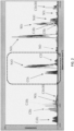
FIG 2 , when the NDIR analyzer is used to measure the concentration of N2O in a sample gas, the infrared absorption wavelength range of carbon monoxide (CO) overlaps the infrared absorption wavelength range of N2O, and CO is an interference component of N2O in its infrared absorption wavelength range. For this reason, attempts have been made to reduce the interference effects of CO by oxidizing CO in the sample gas to carbon dioxide (CO2) using an oxidation catalyst. - However, the oxidation catalyst, which oxidizes CO to CO2, is a consumable item that requires periodic replacement and other maintenance, resulting in high running costs.
- Patent Document 1:
JP 2013-96889 A - The present invention was developed to solve the above-mentioned problems, and its main object is to reduce running costs by eliminating the need for a catalyst, which is a consumable item.
- An infrared gas analyzer according to the present invention is characterized in comprising: a measurement cell into which sample gas is introduced; an infrared light source that irradiates the measurement cell with infrared light; an infrared light detector that detects infrared light that has passed through the measurement cell; and a gas filter within which a plurality of interference components that interfere with a measurement component in the sample gas are enclosed.
- The infrared gas analyzer configured as such has a gas filter within which a plurality of interference components that interfere with the measurement component in the sample gas are enclosed, so that a catalyst that oxidizes or reduces at least one of the plurality of interference components is no longer necessary and, as a result, running costs can be reduced. In addition, since a plurality of interference components are included in the gas filter, the interference effects of a plurality of interference components on the measurement component can be reduced.
- In a specific aspect of the gas filter, it is preferable that the gas filter has enclosed within a plurality of interference components that do not react with each other or a plurality of interference components that are in a state of stable equilibrium with each other.
- The measurement component of the infrared gas analyzer of the present invention is preferably dinitrogen monoxide (N2O), a type of greenhouse gas that contributes to global warming. By measuring the concentration of N2O, the infrared gas analyzer of the present invention can be suitably used in industrial sectors which necessitate a reduction in negative environmental impacts.
- In the infrared light wavelength range, the infrared absorption wavelength range of carbon dioxide (CO2) and the infrared absorption wavelength range of carbon monoxide (CO) each overlap the infrared absorption wavelength range of measurement component N2O. Thus, CO2 and CO are interference components of N2O. In order to remove the interference effects from these interference components, it is preferably that the gas filter has enclosed within carbon dioxide (CO2) gas and carbon monoxide (CO) gas.
- Furthermore, if there are interference components other than CO2 and CO that have interference effects on N2O, said components may be enclosed within the gas filter. For example, if methane (CH4) is included in high concentrations in the sample gas, interference effects of CH4 will arise. Thus, it is preferably that, in addition to CO2 gas and CO gas, the gas filter also has CH4 gas enclosed within.
- An infrared gas analysis method according to the present invention is characterized as being an infrared gas analysis method of analyzing a measurement component in a sample gas by irradiating a measurement cell into which the sample gas has been introduced with infrared light and detecting the infrared light that has passed through the measurement cell with an infrared light detector, wherein interference effects of a plurality of interference components on the measurement component are reduced by using a gas filter within which a plurality of the interference components that interfere with the measurement component are enclosed.
- The infrared gas analyzer according to the present invention may further comprise an arithmetic unit that calculates a concentration of the measurement component in the sample gas using an output of the infrared light detector; and be one wherein the infrared light detector includes a measurement component detector for measuring a concentration of the measurement component and an interference component detector for measuring a concentration of an interference component that interferes with the measurement component; and the arithmetic unit calculates the concentration of the measurement component by subtracting an output of the interference component detector multiplied by a predetermined weighting coefficient from an output of the measurement component detector. In this configuration, since the predetermined weighting coefficient k varies with the concentration of interference components, there is a possibility that measurement errors will occur if a constant weighting coefficient k is used.
- Thus, it is preferably that the arithmetic unit changes or corrects the weighting coefficient based on the concentration of the interference component.
- Moreover, an infrared gas analyzer according to the present invention may be one characterized by comprising a measurement cell into which sample gas is introduced; an infrared light source that irradiates the measurement cell with infrared light; an infrared light detector that detects infrared light that has passed through the measurement cell; and an arithmetic unit that calculates a concentration of a measurement component in the sample gas using an output of the infrared light detector; wherein the infrared light detector includes a measurement component detector for measuring a concentration of the measurement component and an interference component detector for measuring a concentration of an interference component that interferes with the measurement component; and the arithmetic unit, by subtracting an output of the interference component detector multiplied by a predetermined weighting coefficient from an output of the measurement component detector, calculates the concentration of the measurement component and also changes or corrects the weighting coefficient based on the concentration of the interference component.
- The present invention configured as such allows the reduction of running costs by eliminating the need for a catalyst, which is a consumable item.
-
-
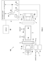
FIG 1 : A schematic diagram showing an infrared gas analyzer of a first embodiment of the present invention. -
FIG 2 : A diagram showing the infrared absorption spectrum of each of several components. -
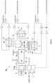
FIG 3 : A schematic diagram showing an infrared gas analyzer according to a variation embodiment of the present invention. -
FIG 4 : A schematic diagram showing an infrared gas analyzer according to a variation embodiment of the present invention. - A first embodiment of an infrared gas analyzer according to the present invention will now be described with reference to the drawings.
- In addition, in each of the drawings shown below, for the purpose of easy understanding, some parts are omitted or exaggerated in schematic form. The same components are denoted by the same reference numerals and the description thereof will be omitted as appropriate.
- The
infrared gas analyzer 100 according to the present embodiment measures the component concentration of dinitrogen monoxide (N2O), nitrogen oxides (NOX), sulfur dioxide (SO2), carbon monoxide (CO), carbon dioxide (CO2), methane (CH4), etc., in sample gases in exhaust gases (flue exhaust gas) emitted from industrial facilities such as sewage treatment facilities, cleaning plants, industrial waste treatment plants and chemical plants via a non-dispersive infrared absorption method (NDIR). - Specifically, the
infrared gas analyzer 100 measures the concentration of N2O in a sample gas and, as shown inFIG 1 , includes ameasurement cell 2 into which the sample gas is introduced, aninfrared light source 3 provided on one end side of themeasurement cell 2 that irradiates themeasurement cell 2 with infrared light, aninfrared light detector 4 provided on the other end side of themeasurement cell 2 that detects infrared light that has passed through themeasurement cell 2, agas filter 5 within which an interference component that interferes with the measurement component (N2O) is enclosed, and anarithmetic unit 6 that calculates the concentration of the measurement component (N2O) having acquired an output from theinfrared light detector 4. - The
measurement cell 2 has, for example, a roughly cylindrical shape, with both end portions sealed bycell window members - The
infrared light source 3 is installed at one end side of themeasurement cell 2, opposite thecell window member 2a, and irradiates infrared light into the interior of themeasurement cell 2. An optical chopper (not shown) is provided between theinfrared light source 3 and themeasurement cell 2, and is configured to, for example, be rotated by a motor, so as to interrupt (chop) the infrared light generated by theinfrared light source 3 at a fixed period. - The
infrared light detector 4 is installed opposite thecell window member 2b on the other end side of themeasurement cell 2, and has ameasurement component detector 41 as the main detector for measuring the concentration of the measurement component (N2O) and aninterference component detector 42 that is a compensation detector for measuring the concentration of the interference component (here, CO2). Themeasurement component detector 41 and theinterference component detector 42 are, in this order, optically arranged in series from said other end side of themeasurement cell 2. The detection signals obtained by themeasurement component detector 41 and the detection signals obtained by theinterference component detector 42 are output to thearithmetic unit 6. - The
measurement component detector 41 is, for example, a pneumatic detector of a condenser microphone type. In themeasurement component detector 41, both end portions of the main body block, which is made of corrosion-resistant metal, are sealed by window members made of infrared transmissive material, and acondenser microphone 41x is installed inside. The interior of themeasurement component detector 41 has enclosed within the measurement component (N2O), or a filler gas for measurement purposes that exhibits equivalent infrared light absorption characteristics, and detects the infrared light intensity in the wavelength range that matches the infrared absorption spectrum of the measurement component. Themeasurement component detector 41 of the present embodiment is sensitive to both the measurement component and interference component. - Since the measurement component in the present embodiment is N2O, a predetermined concentration of N2O gas is enclosed within the
measurement component detector 41. Themeasurement component detector 41 thereby detects infrared light intensity in the wavelength range which matches the infrared absorption spectrum of N2O (seeFIG 2 ). - Similarly to the
measurement component detector 41, theinterference component detector 42 is, for example, a pneumatic detector of a condenser microphone type. In theinterference component detector 42, both end portions of the main body block, which is made of corrosion-resistant metal, are sealed by window members made of infrared transmissive material, and acondenser microphone 42x is placed inside. Theinterference component detector 42 has enclosed within the interference component (CO2), or a filler gas for interference purposes that exhibits equivalent infrared light absorption characteristics, and detects the infrared light intensity in the wavelength range that matches the infrared absorption spectrum of the interference component. Theinterference component detector 42 is provided at the rear of themeasurement component detector 41 and is sensitive to the interference component due to most of the N2O being absorbed by themeasurement component detector 41. - In the present embodiment, to correct for the interference effects of CO2 on N2O, the
interference component detector 42 has enclosed within a higher concentration of N2O gas than the N2O gas in themeasurement component detector 41. Theinterference component detector 42 thereby detects infrared light intensity in the wavelength range which matches the infrared absorption spectrum of CO2 (seeFIG 2 ). - The
gas filter 5 is provided between themeasurement cell 2 andinfrared light detector 4 to reduce or eliminate the absorption spectra of CO2 and CO, which have interference effects on the absorption spectrum of the measurement component (N2O). Specifically, thegas filter 5 has a configuration wherein a mixed gas, which is a mixture of CO2 gas and CO gas, is enclosed within a single chamber. Here, the chamber of thegas filter 5 is sealed at both end portions by window members made of infrared transmissive material. By configuring thegas filter 5 as such as a single chamber, thegas filter 5 can be made smaller, and the loss of infrared light intensity in the infrared absorption wavelength range of N2O due to passing through theinfrared gas filter 5 can be reduced. - The
gas filter 5 of the present embodiment has enclosed within a mixed gas of 60 vol% CO2 gas and 40 vol% CO gas. Thus, enclosed in thegas filter 5 is a mixed gas of a plurality of interference components that do not react with each other, or a mixed gas of a plurality of interference components that are in a state of stable equilibrium with each other. - Because the interference effects of CO2 do not change (increase) significantly when the amount of CO2 gas enclosed within the
gas filter 5 is 50 vol% or more, it is preferable that the amount of CO2 gas be 50 vol% or more. On the other hand, assuming that the sample gas contains a CO concentration roughly estimated to be 1000 ppm, thegas filter 5 should be filled with 20 vol% CO gas to remove the interference effects of that CO. Taking into consideration the amount of CO2 gas enclosed within, the amount of CO gas sealed in thegas filter 5 will be 50 vol% or less. - Furthermore, in the present embodiment, an
optical filter 9 is provided to narrow the wavelengths of infrared light detected by the infraredlight detector 4 in order to reduce the interference effects of components such as SO2 and CH4 in the sample gas. Theoptical filter 9 transmits infrared light in the absorption wavelength range of N2O; specifically, theoptical filter 9 transmits in the wavelength range of 4 µm to 5 µm, for example. Theoptical filter 9 of the present embodiment is provided between themeasurement cell 2 and the infraredlight detector 4; more specifically, theoptical filter 9 is provided between thegas filter 5 and the infraredlight detector 4. - The
arithmetic unit 6 calculates the concentration of N2O based on the difference between the output signal of themeasurement component detector 41 and the output signal of theinterference component detector 42. Thearithmetic unit 6 can display the calculated N2O concentration and other measurement results on adisplay unit 60 which is a display or the like. - Specifically, the
arithmetic unit 6 has ameasurement pre-amplifier 61 that amplifies and outputs the output signal of themeasurement component detector 41, aninterference pre-amplifier 62 that amplifies and outputs the output signal of theinterference component detector 42, anamplifier 63 that multiplies the output from theinterference pre-amplifier 62 by a predetermined weighting coefficient k to amplify it, and asubtractor 64 that subtracts the output signal of theamplifier 63 from the output signal from themeasurement pre-amplifier 61. - Here, the predetermined weighting coefficient k is a coefficient representing the ratio (M2/M1) of the output signal (M2) of the
measurement component detector 41 to the output signal (M1) of theinterference component detector 42 when the interference component (CO2) is measured. The weighting coefficient k is adjusted so as to be close to 1; that is, so that the output signal of themeasurement component detector 41 and the output signal of theinterference component detector 42 are nearly equal. Specifically, one possibility is to adjust the resistance value stored within theinterference pre-amplifier 62 so that the coefficient k approaches 1. Besides that, it is conceivable that the coefficient k could be brought closer to 1 by adjusting the concentration of the filler gas for measurement purposes or the filler gas for interference purposes. - Since the weighting coefficient k described above varies with CO2 concentration, using a constant weighting coefficient k could result in measurement errors. For this reason, the
infrared gas analyzer 100 of the present embodiment is further equipped with a CO2 measurement unit 7 that measures the concentration of CO2 in the sample gas, and the CO2 concentration obtained by the CO2 measurement unit 7 is used to change or correct the weighting coefficient k. - The CO2 measurement unit 7 has a CO2 measurement cell 71 into which sample gas is introduced, an infrared
light irradiation unit 72 that irradiates the CO2 measurement cell 71 with infrared light, and a CO2 detector 73 that detects the infrared light transmitted through theCO2 measurement cell 71. In the present embodiment, the sample gas that has passed through the CO2 measurement cell 71 is introduced into themeasurement cell 2, but the opposite may also be true. - The CO2 measurement cell 71 has the same configuration as the
measurement cell 2 described above, but its cell length is shorter than the cell length of themeasurement cell 2 in accordance with the CO2 concentration. Similarly to themeasurement component detector 41 described above, the CO2 detector 73 is, for example, a pneumatic detector of a condenser microphone type. - Here, the infrared
light irradiation unit 72 is configured to use the infraredlight source 3 described above and alight condensing member 8 provided between the infraredlight source 3 and themeasurement cell 2. Thelight condensing member 8 has a firstoptical path 8a formed by a tapered inner wall surface that concentrates infrared light. By passing through the firstoptical path 8a, infrared light from the infraredlight source 3 is concentrated and irradiated to themeasurement cell 2. A secondoptical path 8b, for irradiating the CO2 measurement cell 71 with infrared light, is connected to the inner wall surface that forms the firstoptical path 8a. Infrared light reflected by the tapered inner wall surface pass through this secondoptical path 8b, and the infrared light that passes through the secondoptical path 8b is irradiated to the CO2 measurement cell 71. - The
arithmetic unit 6 is equipped with a CO2 detection amplifier 65 that amplifies and outputs the output signal of the CO2 detector 73, and the CO2 concentration is calculated from the output signal of said CO2 detection amplifier 65. Here, the output signal of the CO2 detection amplifier 65 or the CO2 concentration obtained therefrom is input to theamplifier 63 of thearithmetic unit 6. - The
amplifier 63 changes or corrects the weighting coefficient k, which is multiplied by the output signal of theinterference component detector 42, in accordance with the output signal of the CO2 detection amplifier 65 or the CO2 concentration obtained therefrom. Here, the weighting coefficient k is determined in advance using a plurality of CO2 gases with known concentrations, and stored in thearithmetic unit 6. Then, when measurement is performed, the weighting coefficient k is changed or corrected in accordance with the output signal of the CO2 detection amplifier 65 or the CO2 concentration obtained therefrom. - In the
infrared gas analyzer 100 of the present embodiment described above, thegas filter 5 removes the interference effects of CO and reduces the interference effects of CO2. Moreover, in theinfrared gas analyzer 100 described above, by using themeasurement component detector 41, which detects N2O and CO2, and theinterference component detector 42, which detects CO2, the interference effects of CO2 added to the output signal of themeasurement component detector 41 are removed by performing the electrical operation of (output of the measured component detector 41) - (output of theinterference component detector 42 x k). - Configured according to the present embodiment, the
infrared gas analyzer 100 has agas filter 5 in which a plurality of interference components (CO2 and CO) that interfere with the measurement component (N2O) in the sample gas are enclosed, so that an oxidation catalyst that oxidizes at least one of the plurality of interference components (here, CO) is no longer necessary and, as a result, running costs can be reduced. In addition, since a plurality of interference components are included in thegas filter 5, the interference effects of a plurality of interference components on the measurement component can be reduced. - In addition, in the present embodiment, since the weighting coefficient k used to calculate N2O concentration is changed or corrected using the CO2 concentration obtained by the CO2 measurement unit 7, the N2O concentration can be accurately determined regardless of the CO2 concentration.
- The
gas filter 5 in the above embodiment was filled with CO2 gas and CO gas as interference components; however, for example, it could also be filled with CH4 gas as an additional interference component. - The
gas filter 5 in the above embodiment is provided between themeasurement cell 2 and the infraredlight detector 4, but it is also possible for it to be installed between the infraredlight source 3 and the measurement cell 2 (if there is alight condensing member 8, between the light condensingmember 8 and the measurement cell 2), as shown inFIG 3 . Also in cases where anoptical filter 9 is provided, it is possible for theoptical filter 9 to be provided between the infraredlight source 3 and the measurement cell 2 (if there is alight condensing member 8, between the light condensingmember 8 and themeasurement cell 2 or between the infraredlight source 3 and the light condensing member 8). Alternatively, thegas filter 5 may be included within the infraredlight source 3 or within themeasurement cell 2. - Furthermore, in the embodiment described above, an
optical filter 9 is used to narrow the wavelength of infrared light detected by the infraredlight detector 4 in order to reduce the interference effects of components such as SO2 and CH4, but theoptical filter 9 does not have to be used. - The infrared gas analyzer of the embodiment described above uses an optical chopping system that interrupts (chops) the infrared light from the infrared
light source 3 at a fixed period using an optical chopper, but it may instead be a fluid modulation system that alternately introduces sample gas and reference gas into themeasurement cell 2 at a fixed period. - Furthermore, the infrared gas analyzer of the embodiment described above measures the concentration of N2O, but it may instead be one that measures the concentration of other components such as NOX, SO2, CO, CO2, CH4, etc., or it may measure the concentration of two or more of said components.
- For example, an example configuration of an
infrared gas analyzer 100 that measures the concentration of each of four components is shown inFIG 4 . Theinfrared gas analyzer 100 shown inFIG 4 measures the concentration of each of four components, for example, N2O, SO2, CO2, and NO, and is equipped with a SO2 measurement unit 10 and aNO measurement unit 11 in addition to the configuration of the embodiment described above. - The SO2
measurement unit 10 has an SO2 detector 101 that detects infrared light transmitted through themeasurement cell 2. TheNO measurement unit 11 has anNO detector 111 that detects infrared light transmitted through themeasurement cell 2. Similarly to themeasurement component detector 41 described above, the SO2 detector 101 and theNO detector 111 are, for example, pneumatic detectors of a condenser microphone type. - In this example configuration, the infrared light transmitted through the
measurement cell 2 is split towards infrared light detector 4 (N2O detector), SO2detector 101, and NOdetector 111 using abeam splitter 12 that uses half mirrors M1, M2, etc. - As shown in
FIG 4 , agas filter 5 similar to that of the previous embodiment is provided between thebeam splitter 12 and the infrared light detector 4 (N2O detector). Here, anoptical filter 9 is also provided between thebeam splitter 12 and the infrared light detector 4 (N2O detector). Moreover,optical filters beam splitter 12 and the SO2 detector 101 and between thebeam splitter 12 and theNO detector 111. In addition, a gas filter may be provided between thebeam splitter 12 and the SO2 detector 101 and between thebeam splitter 12 and theNO detector 111 to remove the interference effects of interference components on their measurement components. AlthoughFIG 4 shows an example of a configuration that measures the concentration of four components, it can be configured to measure the concentration of three components or the concentration of five or more components by changing the configuration of the beam splitter, for example. - The above embodiment analyzes exhaust gas emitted from external combustion engines, but it can also be used to analyze exhaust gas emitted from internal combustion engines of vehicles, ships, etc.
- Various other variations and combinations of embodiments may be made as long as they do not contradict the purpose of the present invention.
- The present invention allows the reduction of running costs by eliminating the need for a catalyst, which is a consumable item.
-
- 100: infrared gas analyzer
- 2: measurement cell
- 3: infrared light source
- 4: infrared light detector
- 41: measurement component detector
- 42: interference component detector
- 5: gas filter
- 6: arithmetic unit
- 7: CO2 measurement unit
- 8: light condensing member
- 9: optical filter
Claims (7)
- An infrared gas analyzer, comprising:a measurement cell into which sample gas is introduced;an infrared light source that irradiates the measurement cell with infrared light;an infrared light detector that detects infrared light that has passed through the measurement cell; anda gas filter within which a plurality of interference components that interfere with a measurement component in the sample gas are enclosed.
- The infrared gas analyzer according to claim 1, wherein
the gas filter has enclosed within a plurality of interference components that do not react with each other or a plurality of interference components that are in a state of stable equilibrium with each other. - The infrared gas analyzer according to claim 1 or 2, wherein
the measurement component is dinitrogen monoxide (N2O). - The infrared gas analyzer according to any one of claims 1 to 3, wherein
the plurality of interference components includes carbon dioxide (CO2) and carbon monoxide (CO). - The infrared gas analyzer according to claim 4, wherein
the plurality of interference components includes methane (CH4). - The infrared gas analyzer according to any one of claims 1 to 5, further comprising:
an arithmetic unit that calculates a concentration of the measurement component in the sample gas using an output of the infrared light detector, whereinthe infrared light detector includes a measurement component detector for measuring a concentration of the measurement component and an interference component detector for measuring a concentration of an interference component that interferes with the measurement component; andthe arithmetic unit calculates the concentration of the measurement component by subtracting an output of the interference component detector multiplied by a predetermined weighting coefficient from an output of the measurement component detector, and changes or corrects the weighting coefficient based on the concentration of the interference component. - An infrared gas analysis method of analyzing a measurement component in a sample gas by irradiating a measurement cell into which the sample gas has been introduced with infrared light and detecting the infrared light that has passed through the measurement cell with an infrared light detector, wherein
interference effects of a plurality of interference components on the measurement component are reduced by using a gas filter within which the plurality of interference components that interfere with the measurement component are enclosed.
Applications Claiming Priority (2)
| Application Number | Priority Date | Filing Date | Title |
|---|---|---|---|
| JP2022077168 | 2022-05-09 | ||
| PCT/JP2023/016587 WO2023218983A1 (en) | 2022-05-09 | 2023-04-27 | Infrared gas analyzer, and infrared gas analysis method |
Publications (1)
| Publication Number | Publication Date |
|---|---|
| EP4524549A1 true EP4524549A1 (en) | 2025-03-19 |
Family
ID=88730426
Family Applications (1)
| Application Number | Title | Priority Date | Filing Date |
|---|---|---|---|
| EP23803462.3A Withdrawn EP4524549A1 (en) | 2022-05-09 | 2023-04-27 | Infrared gas analyzer, and infrared gas analysis method |
Country Status (4)
| Country | Link |
|---|---|
| US (1) | US20250321184A1 (en) |
| EP (1) | EP4524549A1 (en) |
| JP (1) | JPWO2023218983A1 (en) |
| WO (1) | WO2023218983A1 (en) |
Families Citing this family (1)
| Publication number | Priority date | Publication date | Assignee | Title |
|---|---|---|---|---|
| EP4671734A1 (en) * | 2024-06-26 | 2025-12-31 | Fraunhofer-Gesellschaft zur Förderung der angewandten Forschung e.V. | SYSTEM AND METHOD FOR DETERMINING A MEASURE OF ABSORPTION OF A SAMPLE |
Family Cites Families (8)
| Publication number | Priority date | Publication date | Assignee | Title |
|---|---|---|---|---|
| JP3291890B2 (en) * | 1994-01-31 | 2002-06-17 | 株式会社島津製作所 | Infrared gas analyzer |
| JPH09178655A (en) * | 1995-12-26 | 1997-07-11 | Shimadzu Corp | Infrared gas analyzer |
| JP3482070B2 (en) * | 1996-04-06 | 2003-12-22 | 株式会社堀場製作所 | Infrared gas analyzer |
| JPH1082740A (en) * | 1996-09-06 | 1998-03-31 | Shimadzu Corp | Infrared gas analyzer |
| JP2001208685A (en) * | 2000-01-28 | 2001-08-03 | Horiba Ltd | Ftir gas analyzer |
| JP2013096889A (en) | 2011-11-02 | 2013-05-20 | Fuji Electric Co Ltd | Infrared gas analyzer |
| JP6168172B2 (en) * | 2016-01-29 | 2017-07-26 | 株式会社島津製作所 | Infrared gas analyzer |
| JP6951167B2 (en) * | 2016-11-29 | 2021-10-20 | 株式会社堀場製作所 | Gas analyzer and gas analysis method |
-
2023
- 2023-04-27 EP EP23803462.3A patent/EP4524549A1/en not_active Withdrawn
- 2023-04-27 WO PCT/JP2023/016587 patent/WO2023218983A1/en not_active Ceased
- 2023-04-27 JP JP2024520391A patent/JPWO2023218983A1/ja active Pending
- 2023-04-27 US US18/863,980 patent/US20250321184A1/en active Pending
Also Published As
| Publication number | Publication date |
|---|---|
| US20250321184A1 (en) | 2025-10-16 |
| JPWO2023218983A1 (en) | 2023-11-16 |
| WO2023218983A1 (en) | 2023-11-16 |
Similar Documents
| Publication | Publication Date | Title |
|---|---|---|
| US8654334B1 (en) | Incoherent cavity ringdown spectroscopy gas analyzer coupled with periodic chemical scrubbing | |
| EP1914545A2 (en) | Vehicle-mountable exhaust gas analyzer | |
| KR102114557B1 (en) | A NDIR analyzer using Two Functional Channels | |
| EP1507140B1 (en) | Analysis method and apparatus for measuring concentrations of sulfur components using ultraviolet fluorescence | |
| US20250321184A1 (en) | Infrared gas analyzer, and infrared gas analysis method | |
| Xu et al. | Design of nitrogen oxide detection system based on non-dispersive infrared technology | |
| JP3024904B2 (en) | Optical gas analyzer | |
| US12111254B2 (en) | Sample analyzing apparatus | |
| JP2004279339A (en) | Concentration measuring device | |
| EP4276444A1 (en) | Optical co2 concentration meter based on ir light absorption in gas | |
| JP4205821B2 (en) | Correction method for influence of coexisting gas in gas analysis by infrared absorption method and gas analyzer | |
| JP2004138467A (en) | Ultraviolet absorption type measuring instrument and method for treating measurement specimen | |
| JP2025068965A (en) | Gas measuring device and gas measuring method | |
| JP2024089865A (en) | Infrared gas analyzer, infrared gas analysis method, and concentration calculation program | |
| JPWO2023095864A5 (en) | ||
| JPWO2023095876A5 (en) | ||
| RU134648U1 (en) | LIDAR SYSTEM FOR REMOTE MEASUREMENT OF CONCENTRATIONS OF POLLUTANTS IN THE ATMOSPHERE | |
| CN111912804B (en) | Ultraviolet spectrum detection method and device for monitoring trace sulfur dioxide in blast furnace flue gas | |
| JP2025160644A (en) | Infrared gas analyzer, infrared gas analysis method, and infrared gas analysis program | |
| JP2010025829A (en) | Optical interference carbon concentration meter | |
| JPH0452891B2 (en) | ||
| JPS5957143A (en) | Measurement of nox concentration | |
| JPH0933429A (en) | Ozone concentration meter | |
| Sun et al. | Method of sensitivity improving in the non-dispersive infrared gas analysis system | |
| Rahman et al. | IRLAM-An Advanced Technology for NO x Measurement from Diluted Exhaust of a Light Duty Vehicle (LDV) |
Legal Events
| Date | Code | Title | Description |
|---|---|---|---|
| STAA | Information on the status of an ep patent application or granted ep patent |
Free format text: STATUS: THE INTERNATIONAL PUBLICATION HAS BEEN MADE |
|
| PUAI | Public reference made under article 153(3) epc to a published international application that has entered the european phase |
Free format text: ORIGINAL CODE: 0009012 |
|
| STAA | Information on the status of an ep patent application or granted ep patent |
Free format text: STATUS: REQUEST FOR EXAMINATION WAS MADE |
|
| 17P | Request for examination filed |
Effective date: 20241108 |
|
| AK | Designated contracting states |
Kind code of ref document: A1 Designated state(s): AL AT BE BG CH CY CZ DE DK EE ES FI FR GB GR HR HU IE IS IT LI LT LU LV MC ME MK MT NL NO PL PT RO RS SE SI SK SM TR |
|
| DAV | Request for validation of the european patent (deleted) | ||
| DAX | Request for extension of the european patent (deleted) | ||
| STAA | Information on the status of an ep patent application or granted ep patent |
Free format text: STATUS: THE APPLICATION HAS BEEN WITHDRAWN |
|
| 18W | Application withdrawn |
Effective date: 20260122 |