EP4524507A1 - Verfahren und anordnung zum ermitteln einer reihenfolge aneinandergereihter kommunikationsfähiger module - Google Patents
Verfahren und anordnung zum ermitteln einer reihenfolge aneinandergereihter kommunikationsfähiger module Download PDFInfo
- Publication number
- EP4524507A1 EP4524507A1 EP24198415.2A EP24198415A EP4524507A1 EP 4524507 A1 EP4524507 A1 EP 4524507A1 EP 24198415 A EP24198415 A EP 24198415A EP 4524507 A1 EP4524507 A1 EP 4524507A1
- Authority
- EP
- European Patent Office
- Prior art keywords
- modules
- module
- magnetic signal
- detected
- arrangement
- Prior art date
- Legal status (The legal status is an assumption and is not a legal conclusion. Google has not performed a legal analysis and makes no representation as to the accuracy of the status listed.)
- Granted
Links
Images


Classifications
-
- G—PHYSICS
- G08—SIGNALLING
- G08C—TRANSMISSION SYSTEMS FOR MEASURED VALUES, CONTROL OR SIMILAR SIGNALS
- G08C21/00—Systems for transmitting the position of an object with respect to a predetermined reference system, e.g. tele-autographic system
-
- G—PHYSICS
- G06—COMPUTING OR CALCULATING; COUNTING
- G06F—ELECTRIC DIGITAL DATA PROCESSING
- G06F13/00—Interconnection of, or transfer of information or other signals between, memories, input/output devices or central processing units
- G06F13/14—Handling requests for interconnection or transfer
- G06F13/20—Handling requests for interconnection or transfer for access to input/output bus
-
- G—PHYSICS
- G01—MEASURING; TESTING
- G01D—MEASURING NOT SPECIALLY ADAPTED FOR A SPECIFIC VARIABLE; ARRANGEMENTS FOR MEASURING TWO OR MORE VARIABLES NOT COVERED IN A SINGLE OTHER SUBCLASS; TARIFF METERING APPARATUS; MEASURING OR TESTING NOT OTHERWISE PROVIDED FOR
- G01D5/00—Mechanical means for transferring the output of a sensing member; Means for converting the output of a sensing member to another variable where the form or nature of the sensing member does not constrain the means for converting; Transducers not specially adapted for a specific variable
- G01D5/12—Mechanical means for transferring the output of a sensing member; Means for converting the output of a sensing member to another variable where the form or nature of the sensing member does not constrain the means for converting; Transducers not specially adapted for a specific variable using electric or magnetic means
- G01D5/14—Mechanical means for transferring the output of a sensing member; Means for converting the output of a sensing member to another variable where the form or nature of the sensing member does not constrain the means for converting; Transducers not specially adapted for a specific variable using electric or magnetic means influencing the magnitude of a current or voltage
-
- G—PHYSICS
- G01—MEASURING; TESTING
- G01R—MEASURING ELECTRIC VARIABLES; MEASURING MAGNETIC VARIABLES
- G01R33/00—Arrangements or instruments for measuring magnetic variables
- G01R33/02—Measuring direction or magnitude of magnetic fields or magnetic flux
-
- G—PHYSICS
- G01—MEASURING; TESTING
- G01R—MEASURING ELECTRIC VARIABLES; MEASURING MAGNETIC VARIABLES
- G01R33/00—Arrangements or instruments for measuring magnetic variables
-
- G—PHYSICS
- G05—CONTROLLING; REGULATING
- G05B—CONTROL OR REGULATING SYSTEMS IN GENERAL; FUNCTIONAL ELEMENTS OF SUCH SYSTEMS; MONITORING OR TESTING ARRANGEMENTS FOR SUCH SYSTEMS OR ELEMENTS
- G05B19/00—Program-control systems
- G05B19/02—Program-control systems electric
- G05B19/04—Program control other than numerical control, i.e. in sequence controllers or logic controllers
- G05B19/042—Program control other than numerical control, i.e. in sequence controllers or logic controllers using digital processors
- G05B19/0423—Input/output
-
- G—PHYSICS
- G06—COMPUTING OR CALCULATING; COUNTING
- G06F—ELECTRIC DIGITAL DATA PROCESSING
- G06F2213/00—Indexing scheme relating to interconnection of, or transfer of information or other signals between, memories, input/output devices or central processing units
- G06F2213/40—Bus coupling
Definitions
- the invention relates to a method for determining a sequence in which at least three communication-capable modules are arranged in a row.
- the invention further relates to an arrangement of at least three communication-capable modules arranged in a row, with which such a method can be carried out.
- remote I/O systems i.e., systems for the input and output of signals and/or data that are located remotely from a control device, e.g., in a control cabinet.
- These systems typically comprise a head module, also called a head station, which establishes a connection to the control system, and several I/O (input/output) modules that are connected to the head module.
- the modules each have a DIN rail mount and usually also locking devices for mechanical connection to an adjacent module.
- Mechanical arranging can also be used to establish electrical connections between modules, for example, to establish a power supply bus and/or a data bus between the modules and the head station. Even if it is not absolutely necessary for the functionality of the bus system, it may be of interest for additional services to obtain information about the sequence in which the modules are arranged. For example, this information can simplify troubleshooting on the I/O system, since the physical position of a faulty module can be visualized if the sequence is known.
- a further object is to describe an arrangement of sequentially arranged communication-capable modules suitable for implementing the method.
- a method according to the invention of the type mentioned above is characterized by the following steps: A magnetic signal is transmitted from a first of the modules with a predetermined intensity. The intensity of the signal is then increased, for example, continuously or stepwise, until the signal is detected by a module directly adjacent to the transmitting module, but not by a module not directly adjacent to it. After detecting the signal, the module that detected the signal transmits its identification data via a communication channel to a detection unit, which detects a sequence of the modules using the identification data.
- a magnetic signal is emitted by the first module, independent of the communication channel, and its intensity is increased.
- Increasing the intensity increases the range within which the magnetic signal can be detected by another module with a given detection sensitivity.
- the increase in signal intensity ensures that the signal is first detected by an immediately adjacent module. This module then identifies itself as an immediate neighbor using its identification data, which is transmitted over the communication channel.
- the process thus exploits the increasing range of the magnetic signal to detect a module and then uses the communication channel to transmit the identification data. Furthermore, the communication channel can also be used to coordinate the process among the various participating units, i.e., the modules and the detection unit.
- the sequence determination is independent of the type of communication channel and can be used for both wired and wireless modules. Communication can also take place via a bus system or a network.
- An arrangement according to the invention comprises at least three modules, each having a communication unit, as well as a coil for emitting and/or receiving a magnetic signal.
- the arrangement further comprises a detection unit and is configured to carry out the aforementioned method.
- a module with this distinction is used as the first module, which is located at an outer edge of the array. This eliminates any potential ambivalence that might arise from the possibility of a nearest neighbor on each side.
- Arrays of the type described often have a module at an outer edge that also functions as the bus master for a data bus established among the modules.
- Such a module, which represents the bus master in the array is a preferred choice for the first module of the method according to the invention.
- the signal intensity is further increased until the magnetic signal is detected by another module.
- This additional module also outputs its identification data. Based on the identification data, a list of the arranged modules can be continued, for example. This process can be repeated in the same way until all modules in the arrangement have been detected.
- the output of the signal from the first module is terminated and a further magnetic identification signal is output from the module that has output its identification data.
- the method can also be carried out with an arrangement comprising a large number of modules if the magnetic identification signal, starting from a first module at the edge of the arrangement, does not extend to the last module at the opposite edge of the arrangement.
- said first module then no longer participates in the method and, in particular, no longer reacts to magnetic fields that are still transmitted within the scope of this identification cycle.
- a coil is arranged in each module to output and/or receive the magnetic signal, with an axial direction of the coil being aligned in the direction in which the modules are arranged.
- the coils are positioned within the modules such that all coils are arranged on a common axis when the modules are arranged in series.
- the coils are arranged on a coil core, which also extends in the direction in which the modules are arranged.
- the core is a rod-shaped core open on both sides, in particular a ferrite core.
- the magnetic identification signal is generated by applying an electrical pulse of variable length to the coil.
- the pulse is a rectangular voltage pulse. Due to the coil's inductance, the magnetic field strength increases monotonically, to a first approximation linearly, over time when a rectangular voltage pulse is applied to the coil, so that the signal is generated with a magnetic field strength amplitude that depends on the length of the voltage pulse. Thus, the range of the magnetic signal can be easily changed by varying the pulse length.
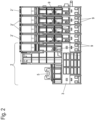
- Figure 1 shows, in a spatial representation, an arrangement 1 of communication-capable modules 2, 2' arranged in a row.
- the modules 2, 2' of the arrangement 1 form, for example, a so-called "Remote I/O" system, i.e. an input or output station for analog and/or digital signals that is connected to a control system and can be positioned remotely from it.
- Figure 2 shows the arrangement 1 according to Figure 1 in a side view.
- module 2 represents a so-called head module (head station) and is also referred to below as head module 2.
- head module 2 The other modules 2' are input and output modules and are also referred to below as I/O modules 2' for the sake of simplicity.
- All modules 2, 2' each have a housing 3, which is shown here in the Figure 1 in the lower area is equipped with a mounting rail holder 4 for snapping onto a mounting rail, for example in a control cabinet.
- Figure 1 The side shown below is facing away from the user when assembly 1 is installed, while the side shown in the Figure 1 The side shown above usually represents a front side of arrangement 1 and is facing the user in the control cabinet.
- the head module 2 includes connectors 5 for connecting a fieldbus, which the head module 2 uses to communicate with a control device (not shown here).
- a CAN bus or an Ethernet-based fieldbus, such as an EtherCAT bus, can be used as a fieldbus connection.
- the connectors 5 are permanently installed in the housing 3.
- the head-end station 2 has further connectors 6, e.g., for the power supply, which are designed as replaceable connector blocks that can be inserted into a corresponding recess on the top of the housing 3.
- the I/O modules 2' are also placed on the mounting rail and are snapped onto the head module 2 or onto an adjacent I/O module 2', whereby the Figure 1
- the arrangement 1 shown is modular.
- the number of four I/O modules 2' shown here is purely exemplary.
- the I/O modules 2' also have interchangeable connectors 6 on their front side when installed in the control cabinet. These connectors are used to connect sensors and/or actuators, for example, in an industrial plant or building automation system.
- a power supply bus and a data bus are formed by contacts (not visible here) on the mutually facing side surfaces of the modules 2, 2', which connect the head module 2 and the I/O modules 2' to each other with regard to a power supply and data exchange.
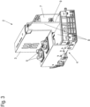
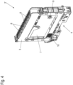
- the internal structure of the head module 2 is also shown again in a partially sectioned drawing in Figure 3 and the internal structure of one of the I/O modules 2' in a representation in Figure 4 , in which a housing side part is removed.
- both the head module 2 and the I/O modules 2' each have at least one printed circuit board 7, which is aligned perpendicular to the mounting rail within the housing 3.
- the head module 2 has further printed circuit boards 8, some of which are arranged in a different orientation than the printed circuit board 7 in the housing 3.
- Data bus contacts 10 can also be seen.
- a coil 9 is arranged at a comparable position on the circuit board 7 for each of the modules 2, 2'.
- the coil 9 is designed as a rod coil on a core open on both sides.
- the core can be a ferrite core, for example.
- the longitudinal axes of all coils 9 lie essentially on an axis that runs parallel to the mounting rail.
- the circuit boards 7, 8 are shown without any additional electrical or electronic components.
- the coils 9 serve, as shown below using a flow chart in Figure 5 explained, according to the application, to detect a respective next, adjacent module 2' starting from the head module 2 and thereby to determine an order of the arrangement of the modules 2, 2' with the aid of a detection unit.
- the Figure 5 The embodiment of a method according to the application for determining the sequence of the modules 2, 2 ⁇ arranged in series is described by way of example with reference to the arrangement 1 of Figures 1 and 2 However, it is understood that the method can also be carried out with other arrangements of modules 2, 2' arranged in series. In particular, it is not necessary for the method to be carried out that the modules 2, 2' are connected to one another via a wired data bus. are, as in the example of the Figures 1 and 2 This is the case.
- the method can also be implemented with modules that are independently part of a wireless communication network.
- the term "communication channel" used in the following explanation is to be understood as non-restrictive in this sense and can be formed via a data bus or a communication network.
- the acquisition unit which coordinates the described procedure and acquires the sequence of the modules 2, 2', is located in the head module 2. This is also not necessary: the procedure could also be coordinated by an acquisition unit located outside the head station 2, as long as the head station 2 and the I/O modules 2' can communicate with this acquisition unit.
- a first step S1 in the flowchart of the Figure 5 is an optional step in which a subsequent detection process is announced to the I/O modules 2' or, if applicable, also to the head module 2. Following this announcement, the modules 2, 2' activate a detection circuit for a signal induced in the respective coil 9. If step S1 is not provided, the corresponding detection circuits are permanently active.
- a voltage pulse of pulse length T is then applied to coil 9 from a first of the modules 2, 2', to which the module number of the initial value is assigned, resulting in the output of a magnetic signal of a specific amplitude.
- coil 9 When coil 9 is subjected to a substantially rectangular voltage pulse, the current in coil 9 increases linearly within the pulse length T, to a first approximation, with the magnetic field strength of the generated magnetic field also increasing linearly. The longer the pulse lasts, the greater the field strength of the magnetic field generated by coil 9 becomes.
- a subsequent step S5 it is determined whether one of the I/O modules 2' has detected the magnetic pulse emitted by the coil 9 of the head module 2.
- the I/O modules 2' monitor a voltage induced in their coil 9. If the induced voltage exceeds a threshold value, the corresponding module 2' sends a message via a communication channel to the detection unit that a magnetic field has been detected.
- the communication channel is in the arrangement 1 of the Figures 1 and 2 the data bus established between the head module 2 and the I/O modules 2'.
- a response from one of the I/O modules 2' is received within a predetermined time period, which, for example, is in the range of one to several milliseconds, the method branches to a next step S6. If no message is received within the predetermined time period, the method continues in a step S8.
- step S6 identification data of this module 2 ⁇ , for example its bus address, sent along with the message of the I/O module 2', are entered in the detection unit into a list in which the order of the modules 2, 2' is subsequently reflected.
- configuration data is sent from the acquisition unit to the I/O module 2' that sent the message, for example, a module number to be assigned to it.
- the value (n+1) is assigned as the module number.
- step S7 the counting variable n is then incremented by the value 1 and the method branches back to step S3, in which the pulse width T is set back to the initial value Tmin.
- step S4 in which a magnetic pulse is emitted.
- the magnetic pulse is no longer emitted by the head-end station 2, but rather by the very I/O module 2' that previously detected the magnetic field. This can be done based on a corresponding command that the detection unit sends to the I/O module 2' via the communication channel.
- the system waits for a response from one of the not yet recognized I/O modules 2'.
- the detected I/O module 2' and in particular the I/O module 2 ⁇ currently emitting the magnetic pulse has deactivated its detection circuit.
- step S5 If in step S5 no further I/O module 2' reports via the communication bus within the predetermined time period that it has detected a magnetic signal, the method continues in step S8, in which the variable T for the pulse width is increased by a predetermined value ⁇ T.
- Steps S4 to S9 are repeated, if necessary, until either one of the previously undetected I/O modules 2' detects the magnetic signal or until the maximum pulse length Tmax is reached.
- the range of the magnetic pulse (for a given detection sensitivity) is increased. In this way, the closest adjacent I/O module 2 is detected as the next module 2, 2'.
- all of the connected I/O modules 2' are successively detected in the order of their arrangement, starting from one side of the arrangement 1 - specifically, starting from the head module 2.
Landscapes
- Physics & Mathematics (AREA)
- General Physics & Mathematics (AREA)
- Engineering & Computer Science (AREA)
- Theoretical Computer Science (AREA)
- General Engineering & Computer Science (AREA)
- Condensed Matter Physics & Semiconductors (AREA)
- Near-Field Transmission Systems (AREA)
Abstract
- Ausgeben eines magnetischen Signals von einem ersten der Module (2, 2') mit einer vorgegebenen Intensität;
- Steigern der Intensität des Signals, bis das Signal von einem unmittelbar an das sendende Modul (2, 2') angrenzenden der Module (2, 2') detektiert wird, von einem nicht unmittelbar angrenzenden der Module (2, 2') jedoch nicht detektiert wird;
- Ausgeben von Identifikationsdaten durch dasjenige der Module (2, 2'), das das magnetische Signal detektiert hat, über einen Kommunikationskanal an eine Erfassungseinheit; und
- Erfassen eine Reihenfolge der Module (2, 2') anhand der Identifikationsdaten.
Description
- Die Erfindung betrifft ein Verfahren zum Ermitteln einer Reihenfolge, in der mindestens drei aneinandergereihte kommunikationsfähige Module angeordnet sind. Die Erfindung betrifft weiterhin eine Anordnung aus mindestens drei aneinanderreihbaren kommunikationsfähigen Modulen, mit der ein derartiges Verfahren durchführbar ist.
- In der Elektroinstallation und der Automatisierungstechnik werden häufig Anordnungen von aneinandergereihten kommunikationsfähigen Modulen eingesetzt. Ein Beispiel aus der Automatisierungstechnik sind sog. "Remote-I/O"-Systeme, also Systeme zur Ein- und Ausgabe von Signalen und/oder Daten, die entfernt von einer Steuereinrichtung z. B. in einem Schaltschrank angeordnet sind. Diese Systeme umfassen i. d. R. ein Kopfmodul, auch Kopfstation genannt, das eine Verbindung zum Steuerungssystem aufbaut, und mehrere I/O (Input/Output, also Eingabe und Ausgabe) - Module, die an das Kopfmodul angereiht werden. Zu dem Zweck weisen die Module jeweils eine Hutschienenaufnahme auf und meist zusätzlich Rastmittel zur mechanischen Verbindung zu einem benachbarten Modul.
- Mit dem mechanischen Anreihen können auch elektrische Verbindungen zwischen den Modulen etabliert werden, die z.B. dem Aufbau eines Stromversorgungsbusses und/oder dem Aufbau eines Datenbusses zwischen den Modulen und Kopfstation dienen. Selbst wenn es für die Funktionalität des Bussystems nicht unbedingt notwendig ist, kann es für zusätzliche Dienste von Interesse sein, Informationen über eine Reihenfolge zu erhalten, in der die Module aneinandergereiht sind. Beispielsweise kann mit dieser Information eine Fehlersuche am I/O-System vereinfacht werden, da die physikalische Position eines fehlerhaften Moduls visualisiert werden kann, wenn die Reihenfolge bekannt ist.
- Die gleiche Problematik kann sich auch bei aneinandergereihten Modulen ergeben, die keinen drahtgebundenen Datenbus beim Aneinanderreihen aufbauen, sondern die unabhängig voneinander drahtlos z.B. mit einem Verteiler, beispielsweise einem Switch oder Gateway, kommunizieren. Auch dabei ist unter Umständen eine Reihenfolge der Aneinanderreihung dieser unabhängig voneinander kommunizierenden Module von Interesse.
- Es ist eine Aufgabe der vorliegenden Erfindung, ein Verfahren zu beschreiben, mit dem eine Reihenfolge von aneinandergereihten kommunikationsfähigen Modulen innerhalb einer Anordnung ermittelt werden kann. Es ist eine weitere Aufgabe, eine zur Durchführung des Verfahrens geeignete Anordnung von aneinanderreihbaren kommunikationsfähigen Modulen zu beschreiben.
- Diese Aufgabe wird gelöst durch ein Verfahren bzw. eine Anordnung mit den Merkmalen des jeweiligen unabhängigen Anspruchs. Vorteilhafte Ausgestaltungen und Weiterbildungen sind Gegenstand der abhängigen Ansprüche.
- Ein erfindungsgemäßes Verfahren der eingangs genannten Art zeichnet sich durch die folgenden Schritte aus: Es wird ein magnetisches Signal von einem ersten der Module mit einer vorgegebenen Intensität gesendet. Die Intensität des Signals wird dann z.B. kontinuierlich oder schrittweise gesteigert, bis das Signal von einem unmittelbar an das sendende Modul angrenzenden Modul detektiert wird, von einem nicht unmittelbar angrenzenden Modul jedoch nicht detektiert wird. Nach dem Detektieren des Signals gibt das Modul, das das Signal detektiert hat, Daten zu seiner Identifizierung über einen Kommunikationskanal an eine Erfassungseinheit aus, die unter Nutzung der Identifikationsdaten eine Reihenfolge der Module erfasst.
- Es wird also erfindungsgemäß unabhängig von dem Kommunikationskanal ein magnetisches Signal von dem ersten Modul ausgegeben, das in seiner Intensität gesteigert wird. Durch die Steigerung der Intensität steigt die Reichweite, innerhalb der das magnetische Signal bei einer gegebenen Detektionssensitivität von einem weiteren Modul detektierbar ist. Das Ansteigen der Intensität des Signals stellt sicher, dass das Signal zuerst von einem unmittelbar benachbarten Modul detektiert wird. Dieses Modul weist sich daraufhin als unmittelbarer Nachbar mithilfe seiner Identifikationsdaten aus, die über den Kommunikationskanal übermittelt werden.
- Das Verfahren nutzt somit die ansteigende Reichweite des magnetischen Signals zur Detektion eines Moduls aus und bedient sich dann des Kommunikationskanals, um die Identifikationsdaten zu übermitteln. Weiter kann der Kommunikationskanal auch zur Koordination des Verfahrens unter den verschiedenen teilnehmenden Einheiten, d.h. den Modulen und der Erfassungseinheit genutzt werden.
- Die Ermittlung der Reihenfolge ist unabhängig von dem Typ des Kommunikationskanals und kann sowohl bei drahtgebunden kommunizierenden, als auch bei drahtlos kommunizierenden Modulen eingesetzt werden. Auch kann die Kommunikation über ein Bussystem oder über ein Netzwerk stattfinden.
- Eine erfindungsgemäße Anordnung umfasst mindestens drei Module, die jeweils eine Kommunikationseinheit aufweisen, sowie eine Spule zum Abgeben und/oder Empfangen eines magnetischen Signals. Die Anordnung umfasst weiter eine Erfassungseinheit und ist zur Durchführung des zuvor genannten Verfahrens eingerichtet.
- Bevorzugt wird als erstes Modul ein insofern ausgezeichnetes Modul eingesetzt, das sich an einem äußeren Rand der Anordnung befindet. Eine mögliche Ambivalenz, die daher rührt, dass es zu jeder Seite einen nächsten Nachbarn geben könnte, wird so ausgeschaltet. Häufig weisen Anordnungen der beschriebenen Art an einem äußeren Rand ein Modul auf, das auch als Busmaster für einen unter den Modulen aufgebauten Datenbus fungiert. Eine solches Modul, das den Busmaster in der Anordnung darstellt, ist eine bevorzugte Wahl für das erste Modul des erfindungsgemäßen Verfahrens.
- In einer vorteilhaften Weiterbildung des Verfahrens ist vorgesehen, dass nach dem Ausgeben der Identifikationsdaten des empfangenden Moduls die Intensität des Signals weiter gesteigert wird, bis das magnetische Signal von einem weiteren Modul detektiert wird. Auch dieses weitere Modul gibt seine Identifikationsdaten aus. Anhand der Identifikationsdaten kann z.B. eine Liste der angeordneten Module fortgeführt werden. Dieses Verfahren kann auf gleiche Weise wiederholt werden, bis alle Module der Anordnung erfasst sind.
- In einer weiteren vorteilhaften Ausgestaltung des Verfahrens ist vorgesehen, nach einem Detektieren des Signals die Ausgabe des Signals von dem ersten Modul zu beenden und ein weiteres magnetisches Identifikationssignal von dem Modul auszugeben, das seine Identifikationsdaten ausgegeben hat. Auf diese Weise kann das Verfahren auch bei Anordnung auch mit einer großen Zahl von Modulen durchgeführt werden, wenn das magnetische Identifikationssignal ausgehend von einem ersten Modul am Rand der Anordnung sich nicht bis zum letzten Modul am gegenüberliegenden Rand der Anordnung erstreckt. Bevorzugt beteiligt sich das genannte erste Modul dann nicht weiter an dem Verfahren und reagiert insbesondere auch nicht mehr auf Magnetfelder, die im Rahmen dieses Identifikationszyklus noch gesendet werden.
- Zur Ausgabe und/oder zum Empfangen des magnetischen Signals ist in einer Ausgestaltung eine Spule in jedem Modul angeordnet, wobei eine axiale Richtung der Spule in Anreihrichtung der Module ausgerichtet ist. Bevorzugt sind die Spulen so innerhalb der Module positioniert, dass alle Spulen beim Aneinanderreihen der Module auf einer gemeinsamen Achse angeordnet sind. Bevorzugt sind die Spulen auf einem Spulenkern angeordnet, der sich ebenfalls in Anreihrichtung der Module erstreckt. Besonders bevorzugt ist der Kern ein stabförmiger und zu beiden Seiten offener Kern, insbesondere ein Ferritkern.
- Weiter bevorzugt wird das magnetische Identifizierungssignal erzeugt, indem ein elektrischer Puls mit variabler Länge auf die Spule aufgeschaltet wird. Insbesondere ist der Puls ein rechteckförmiger Spannungspuls. Durch die Induktivität der Spule steigt bei einem rechteckförmigen Spannungspuls, der auf die Spule gegeben wird, die magnetische Feldstärke monoton, in erster Näherung linear, mit der Zeit an, so dass das Signal mit einer magnetischen Feldstärkeamplitude erzeugt wird, die von der Länge des Spannungspulses abhängig ist. Damit kann die Reichweite des Magnetsignals auf einfache Weise durch Variation der Pulslänge verändert werden.
- Die Erfindung wird nachfolgend anhand von Ausführungsbeispielen mithilfe von Figuren näher erläutert. Die Figuren zeigen:
- Figur 1
- eine Anordnung mehrerer kommunikationsfähiger aneinandergereihter Module in einer räumlichen Darstellung;
- Figur 2
- eine Seitenansicht der Anordnung gemäß
Figur 1 ; - Figur 3
- eine teilgeschnittene räumliche Darstellung eines Kopfmoduls der Anordnung der
Figuren 1 und2 ; - Figur 4
- eine räumliche Darstellung eines weiteren Moduls der Anordnung der
Figuren 1 und2 ; und - Figur 5
- ein Flussdiagramm eines Ausführungsbeispiels eines Verfahrens zur Bestimmung einer Reihenfolge aneinandergereihter Module.
-
Figur 1 zeigt zunächst in einer räumlichen Darstellung eine Anordnung 1 aneinandergereihter kommunikationsfähiger Module 2, 2'. Die Module 2, 2' der Anordnung 1 bilden hier beispielhaft ein sogenanntes "Remote I/O"-System, also eine Ein- bzw. Ausgabestation für analoge und oder digitale Signale, die mit einem Steuerungssystem verbunden ist und entfernt von dieser positioniert sein kann.Figur 2 zeigt die Anordnung 1 gemäßFigur 1 in einer Seitenansicht. - Bei der gezeigten Anordnung 1 stellt das Modul 2 ein sogenanntes Kopfmodul (Kopfstation) dar und wird nachfolgend auch als Kopfmodul 2 bezeichnet. Die weiteren Module 2' sind Ein- und Ausgabemodule und werden der einfacheren Darstellung nachfolgend auch als I/O-Module 2' bezeichnet.
- Alle Module 2, 2' weisen jeweils ein Gehäuse 3 auf, das hier in der
Figur 1 im unteren Bereich mit einer Tragschienenaufnahme 4 zum Aufrasten auf eine Tragschiene zum Beispiel in einem Schaltschrank ausgestattet ist. Die in derFigur 1 unten dargestellte Seite ist bei Montage der Anordnung 1 vom Benutzer abgewandt, während die in derFigur 1 oben dargestellte Seite in der Regel eine Frontseite der Anordnung 1 darstellt und im Schaltschrank dem Benutzer zugewandt ist. - Das Kopfmodul 2 umfasst Anschlüsse 5, die zum Anschließen eines Feldbusses dienen, mit dem das Kopfmodul 2 mit einer hier nicht dargestellten Steuereinrichtung kommuniziert. Als Feldbusanschluss kann z.B. ein CAN-Bus oder auch ein Ethernet-basierter Feldbus, zum Beispiel ein EtherCAT-Bus eingesetzt werden.
- Die Anschlüsse 5 sind fest in das Gehäuse 3 eingebaut. Daneben weist die Kopfstation 2 noch weitere Anschlüsse 6, z.B. zur Stromversorgung, auf, die austauschbar in Form von Anschlussblöcken ausgebildet sind, die in eine entsprechende Aussparung an der Oberseite des Gehäuses 3 eingesetzt werden können.
- Die I/O-Module 2' werden ebenfalls auf die Tragschiene aufgesetzt und werden an das Kopfmodul 2 bzw. an ein benachbartes I/O-Modul 2' angerastet, wodurch die in der
Figur 1 dargestellte Anordnung 1 modular entsteht. Die Anzahl von hier vier I/O-Modulen 2' ist rein beispielhaft. Die I/O-Modulen 2' weisen an ihrer im Einbauzustand im Schaltschrank vorderen Seite ebenfalls austauschbare Anschlüsse 6 auf. Diese Anschlüsse dienen einer Verbindung mit Sensoren und/oder Aktoren beispielsweise einer Industrieanlage oder einer Gebäudeautomation. - Beim Aneinanderreihen der Module 2, 2' wird durch hier nicht sichtbare Kontakte an den einander zugewandten Seitenflächen der Module 2, 2' ein Energieversorgungsbus und ein Datenbus gebildet, der das Kopfmodul 2 und die I/O-Module 2' untereinander im Hinblick auf eine Stromversorgung und einen Datenaustausch miteinander verbindet.
- Der innere Aufbau des Kopfmoduls 2 ist auch nochmals in einer teilweise geschnittenen Zeichnung in
Figur 3 wiedergegeben und der innere Aufbau eines der I/O-Module 2' in einer Darstellung inFigur 4 , bei der ein Gehäuseseitenteil entfernt ist. In diesen Darstellungen ist zu erkennen, dass sowohl das Kopfmodul 2 als auch die I/O-Module 2' jeweils mindestens eine Leiterplatte 7 aufweisen, die innerhalb des Gehäuses 3 senkrecht zur Tragschiene ausgerichtet ist. Das Kopfmodul 2 weist weitere Leiterplatten 8 auf, die teilweise auch in anderer Orientierung als die Leiterplatte 7 im Gehäuse 3 angeordnet sind. Bei dem I/O-Modul 2' sind in der Darstellung derFigur 4 auch Datenbuskontakte 10 erkennbar. - An jeweils vergleichbarer Position auf der Leiterplatte 7 ist bei jedem der Module 2, 2' eine Spule 9 angeordnet. Beispielhaft ist die Spule 9 als Stabspule auf einem beidseitig offenen Kern ausgebildet. Der Kern kann beispielsweise ein Ferritkern sein. Wenn die Module 2, 2' zu der Anordnung 1 aneinandergereiht sind, liegen die Längsachsen aller Spulen 9 im Wesentlichen auf einer Achse, die parallel zur Tragschiene verläuft. Der einfachen Darstellung halber sind die Leiterplatten 7, 8 ohne weitere elektrische bzw. elektronische Bauelemente dargestellt.
- Die Spulen 9 dienen, wie nachfolgend anhand eines Flussdiagramms in
Figur 5 erläutert wird, anmeldungsgemäß dazu, ein jeweils nächstes, benachbartes Modul 2' ausgehend von dem Kopfmodul 2 zu detektieren und dadurch eine Reihenfolge der Anordnung der Module 2, 2' mithilfe einer Erfassungseinheit zu ermitteln. - Das in der
Figur 5 dargestellte Ausführungsbeispiel eines anmeldungsgemäßen Verfahrens zum Ermitteln der Reihenfolge der angereihten Module 2, 2` wird beispielhaft mit Bezug auf die Anordnung 1 derFiguren 1 und2 erläutert. Es versteht sich aber, dass das Verfahren auch bei anderen Anordnungen von aneinandergereihten Modulen 2, 2' ausgeführt werden kann. Insbesondere ist es auch für die Durchführung des Verfahrens nicht erforderlich, dass die Module 2, 2' untereinander über einen drahtgebundenen Datenbus verbunden sind, wie das beim Beispiel derFiguren 1 und2 der Fall ist. Das Verfahren kann auch mit Modulen durchgeführt werden, die unabhängig voneinander Teil eines drahtlosen Kommunikationsnetzwerk sind. Der in der folgenden Erläuterung benutzte Begriff "Kommunikationskanal" ist in diesem Sinne als nicht einschränkend zu verstehen und kann über einen Datenbus oder ein Kommunikationsnetzwerk gebildet sein. - Für das folgende Verfahren wird davon ausgegangen, dass die genannte Erfassungseinheit, die das beschriebene Verfahren koordiniert und die Reihenfolge der Module 2, 2' erfasst, in dem Kopfmodul 2 angeordnet ist. Auch dieses ist keine Notwendigkeit: das Verfahren könnte auch von einer Erfassungseinheit koordiniert werden, die außerhalb der Kopfstation 2 angeordnet ist, solange die Kopfstation 2 und die I/O- Module 2' mit dieser Erfassungseinheit kommunizieren können.
- Ein erster Schritt S1 in dem Flussdiagramm der
Figur 5 ist ein optionaler Schritt, in dem ein sich anschließender Erfassungsvorgang den I/O-Modulen 2' bzw. gegebenenfalls auch dem Kopfmodul 2 angekündigt wird. Nach dieser Ankündigung aktivieren die Module 2, 2' eine Detektionsschaltung für ein in der jeweiligen Spule 9 induziertes Signal. Wenn der Schritt S1 nicht vorgesehen ist, sind die entsprechenden Detektionsschaltungen dauerhaft aktiv. - In einem folgenden Schritt S2 wird eine Zählvariable n für eine Modulnummer auf einen Initialwert gesetzt, beispielsweise auf den Wert null: n=0.
- In einem folgenden Schritt S3 wird eine Variable T für eine Pulslänge ebenfalls auf einen Initialwert, beispielhaft den Wert Tmin, gesetzt: T=Tmin.
- In einem darauffolgenden Schritt S4 wird dann von einem ersten der Module 2, 2`, dem die Modulnummer des Initialwerts zugeordnet wird, ein Spannungsimpuls der Pulslänge T auf die Spule 9 gegeben, der zur Ausgabe eines magnetischen Signal einer bestimmten Amplitude führt. Es wird beispielhaft davon ausgegangen, dass das Modul mit der initialen Nummer (n=0) das Kopfmodul 2 ist.
- Wenn die Spule 9 mit einem i.W. rechteckförmigen Spannungspuls beaufschlagt wird, steigt ein Strom in der Spule 9 innerhalb der Pulslänge T in erster Näherung linear an, wobei die Magnetfeldstärke des aufgebauten Magnetfelds ebenfalls linear steigt. Je länger der Puls andauert, umso größer wird somit die Feldstärke des Magnetfelds, das die Spule 9 aufbaut.
- In einem folgenden Schritt S5 wird ermittelt, ob eines der I/O-Module 2' den von der Spulen 9 des Kopfmoduls 2 ausgegebenen Magnetpuls detektiert hat. Zu diesem Zweck überwachen die I/O-Module 2' eine in ihrer Spule 9 induzierte Spannung. Falls die induzierte Spannung einen Schwellenwert übersteigt, sendet das entsprechende Modul 2' eine Nachricht über einen Kommunikationskanal an die Erfassungseinheit, dass ein Magnetfeld erkannt wurde. Der Kommunikationskanal ist in der Anordnung 1 der
Figuren 1 und2 der zwischen dem Kopfmodul 2 und den I/O-Modulen 2' aufgebaute Datenbus. - Wenn eine Antwort eines der I/O-Module 2' innerhalb einer vorgegebenen Zeitspanne, die beispielsweise im Bereich von einer bis mehreren Millisekunden liegt, empfangen wird, verzweigt das Verfahren zu einem nächsten Schritt S6. Falls keine Nachricht innerhalb der vorgegebenen Zeitspanne empfangen wird, wird das Verfahren in einem Schritt S8 fortgeführt.
- In dem Schritt S6 werden mit der Nachricht des I/O-Moduls 2' mitgesendete Identifikationsdaten dieses Moduls 2`, beispielsweise seine Busadresse, in der Erfassungseinheit in eine Liste eingetragen, in der sich nachfolgend die Reihenfolge der Module 2, 2' widerspiegelt.
- Weiter kann vorgesehen sein, dass Konfigurationsdaten von der Erfassungseinheit an das I/O-Modul 2`, das die Nachricht gesendet hat, geschickt werden, beispielsweise eine ihm zuzuordnende Modulnummer. Vorteilhaft wird als Modulnummer der Wert (n+1) zugeordnet.
- In einem folgenden Schritt S7 wird die Zählvariable n dann um den Wert 1 inkrementiert und das Verfahren verzweigt zurück zum Schritt S3, in dem die Pulsbreite T wieder auf den Initialwert Tmin gesetzt wird.
- Das Verfahren durchläuft dann erneut den Schritt S4, in dem ein Magnetpuls ausgegeben wird, allerdings wird jetzt der Magnetpuls nicht mehr von der Kopfstation 2, sondern von eben jenem I/O-Modul 2' ausgegeben, das zuvor das Magnetfeld detektiert hatte. Dieses kann auf Basis eines entsprechenden Befehls erfolgen, den die Erfassungseinheit an das I/O-Modul 2' über den Kommunikationskanal sendet.
- Wiederum wird in dem erneut durchlaufenden folgenden Schritt S5 auf eine Antwort eines der noch nicht erkannten I/O-Module 2' gewartet. Ein bereits erkanntes I/O-Modul 2' und insbesondere auch das den Magnetimpuls aktuell abgebende I/O-Modul 2`, hat seine Detektionsschaltung deaktiviert.
- Wenn in dem Schritt S5 innerhalb der vorgegebenen Zeitspanne kein weiteres I/O-Modul 2' über den Kommunikationsbus mitteilt, dass es ein magnetisches Signal detektiert hat, wird das Verfahren in dem Schritt S8 fortgeführt, in dem die Variable T für die Pulsbreite um einen vorgegebenen Wert ΔT erhöht wird.
- In einem nächsten Schritt S9 wird überprüft, ob eine vorgegebene maximale Pulslänge Tmax erreicht ist. Wenn die maximale Pulslänge Tmax erreicht ist, wird das Verfahren beendet. Wenn die maximale Pulslänge Tmax nicht erreicht ist, verzweigt das Verfahren zurück zu dem Schritt S4, in dem ein Magnetpuls vom gleichen I/O-Modul 2' wie zuvor erneut ausgegeben wird, diesmal allerdings mit der um den Wert ΔT verlängerten Pulslänge T und damit mit größerer Amplitude des Magnetfelds.
- Die Schritte S4 bis S9 werden ggf. so lange wiederholt, bis entweder eines der bislang noch nicht erfassten I/O-Module 2' das magnetische Signal detektiert oder bis die maximale Pulslänge Tmax erreicht ist. Durch die schrittweise Erhöhung der Magnetfeldamplitude wird dabei die Reichweite des Magnetpulses (bei gegebener Detektionssensitivität) erhöht. Auf diese Weise wird erreicht, dass jeweils das am nächsten benachbarte I/O-Modul 2 als nächstes Modul 2, 2' detektiert wird. Bei dem Verfahren werden so sukzessive ausgehend von einer Seite der Anordnung 1 - hier konkret ausgehend von dem Kopfmodul 2 - alle angereihten I/O-Module 2' in der Reihenfolge ihrer Anordnung erfasst.
-
- 1
- Anordnung
- 2
- Modul (Kopfmodul)
- 2'
- weiteres Modul (I/O-Modul)
- 3
- Gehäuse
- 4
- Tragschienenaufnahme
- 5
- Anschluss (fest)
- 6
- Anschluss (austauschbar)
- 7
- Leiterplatte
- 8
- weitere Leiterplatte
- 9
- Spule
- 10
- Datenbuskontakte
Claims (12)
- Verfahren zum Ermitteln einer Reihenfolge, in der mindestens drei aneinandergereihte kommunikationsfähige Module (2, 2`) angeordnet sind, aufweisend die folgenden Schritte:- Ausgeben eines magnetischen Signals von einem ersten der Module (2, 2`) mit einer vorgegebenen Intensität;- Steigern der Intensität des Signals, bis das Signal von einem unmittelbar an das sendende Modul (2, 2') angrenzenden der Module (2, 2`) detektiert wird, von einem nicht unmittelbar angrenzenden der Module (2, 2`) jedoch nicht detektiert wird;- Ausgeben von Identifikationsdaten durch dasjenige der Module (2, 2`), das das magnetische Signal detektiert hat, über einen Kommunikationskanal an eine Erfassungseinheit; und- Erfassen eine Reihenfolge der Module (2, 2`) anhand der Identifikationsdaten.
- Verfahren nach Anspruch 1, bei dem nach dem Ausgeben der Identifikationsdaten durch dasjenige der Module (2, 2`), das das magnetische Signal detektiert hat, die Intensität des von dem ersten der Module (2, 2`) gesendeten magnetischen Signal weiter gesteigert wird, bis das magnetische Signal von einem weiteren der Module (2, 2`) detektiert wird, das dann Identifikationsdaten über den Kommunikationskanal an die Erfassungseinheit übermittelt.
- Verfahren nach Anspruch 1, bei dem nach dem Ausgeben der Identifikationsdaten dasjenige der Module (2, 2`), das das magnetische Signal detektiert hat, das sich ausgehend von der vorgegebenen Intensität steigernde magnetische Signal ausgibt, bis das magnetische Signal von einem weiteren der Module (2, 2`) detektiert wird, das dann Identifikationsdaten über den Kommunikationskanal an die Erfassungseinheit übermittelt.
- Verfahren nach Anspruch 2 oder 3, bei dem die Schritte des Ausgebens des magnetischen Signals, des Detektierens des magnetischen Signals durch ein weiteres der Module (2, 2`) und des Übermittelns der Identifikationsdaten wiederholt durchgeführt werden, bis alle Module (2, 2`) der Anordnung (1) erfasst sind.
- Verfahren nach einem der Ansprüche 1 bis 4, bei die Erfassungseinheit nach dem Empfangen der Identifikationsdaten Konfigurationsdaten an das Modul (2, 2`), das die Identifikationsdaten gesendet hat, übermittelt.
- Verfahren nach einem der Ansprüche 1 bis 5, bei dem das magnetische Signal durch jeweils eine Spule (9) erzeugt und/oder detektiert wird, die in jedem der Module (2, 2`) angeordnet ist.
- Verfahren nach Anspruch 6, bei dem das magnetische Signal ein Magnetpuls ist, der durch Beaufschlagen der Spule (9) mit einem rechteckförmigen Spannungssignal einer vorgebbaren Pulsbreite (T) erzeugt wird.
- Verfahren nach Anspruch 7, bei dem die Intensität des magnetischen Signals dadurch gesteigert wird, dass die Pulsbreite (T) erhöht wird.
- Anordnung (1) aus mindestens drei aneinanderreihbaren kommunikationsfähigen Modulen (2, 2`), die jeweils eine Spule (9) zum Ausgeben und/oder Empfangen eines magnetischen Signals aufweisen, sowie einer Erfassungseinheit, wobei die Anordnung (1) zur Durchführung eines Verfahrens nach einem der Ansprüche 1 bis 8 ausgebildet ist.
- Anordnung (1) nach Anspruch 9, bei der alle Spulen (9) entlang einer gemeinsamen Achse angeordnet sind.
- Anordnung (1) nach Anspruch 9 oder 10, bei der die Spulen (9) Stabspulen sind.
- Anordnung (1) nach einem der Ansprüche 9 bis 11, bei der die Spulen (9) einen Ferritkern aufweisen.
Applications Claiming Priority (1)
| Application Number | Priority Date | Filing Date | Title |
|---|---|---|---|
| DE102023124841.3A DE102023124841A1 (de) | 2023-09-14 | 2023-09-14 | Verfahren und Anordnung zum Ermitteln einer Reihenfolge aneinandergereihter kommunikationsfähiger Module |
Publications (2)
| Publication Number | Publication Date |
|---|---|
| EP4524507A1 true EP4524507A1 (de) | 2025-03-19 |
| EP4524507B1 EP4524507B1 (de) | 2026-01-21 |
Family
ID=92675973
Family Applications (1)
| Application Number | Title | Priority Date | Filing Date |
|---|---|---|---|
| EP24198415.2A Active EP4524507B1 (de) | 2023-09-14 | 2024-09-04 | Verfahren und anordnung zum ermitteln einer reihenfolge aneinandergereihter kommunikationsfähiger module |
Country Status (4)
| Country | Link |
|---|---|
| US (1) | US20250094369A1 (de) |
| EP (1) | EP4524507B1 (de) |
| CN (1) | CN119618273A (de) |
| DE (1) | DE102023124841A1 (de) |
Citations (4)
| Publication number | Priority date | Publication date | Assignee | Title |
|---|---|---|---|---|
| EP2031625A1 (de) * | 2007-09-03 | 2009-03-04 | Siemens Aktiengesellschaft | Verfahren zum Erkennen von Komponenten in einer elektrischen Niederspannungs-Schaltanlage |
| US7773569B2 (en) * | 2005-05-19 | 2010-08-10 | Meshnetworks, Inc. | System and method for efficiently routing data packets and managing channel access and bandwidth in wireless multi-hopping networks |
| DE102005025703B4 (de) * | 2005-06-04 | 2015-09-10 | Phoenix Contact Gmbh & Co. Kg | Vorrichtung zur Adressierung und Positionsbestimmung eines Gerätemoduls |
| US20170116145A1 (en) * | 2014-04-03 | 2017-04-27 | Phoenix Contact Gmbh & Co. Kg | Electrical interface module |
Family Cites Families (1)
| Publication number | Priority date | Publication date | Assignee | Title |
|---|---|---|---|---|
| DE10315646A1 (de) * | 2003-04-04 | 2004-11-11 | Abb Patent Gmbh | Schaltanlage und Verfahren zur Einschubebenenerkennung in einer Schaltanlage |
-
2023
- 2023-09-14 DE DE102023124841.3A patent/DE102023124841A1/de active Pending
-
2024
- 2024-09-04 EP EP24198415.2A patent/EP4524507B1/de active Active
- 2024-09-13 CN CN202411285313.6A patent/CN119618273A/zh active Pending
- 2024-09-13 US US18/884,348 patent/US20250094369A1/en active Pending
Patent Citations (4)
| Publication number | Priority date | Publication date | Assignee | Title |
|---|---|---|---|---|
| US7773569B2 (en) * | 2005-05-19 | 2010-08-10 | Meshnetworks, Inc. | System and method for efficiently routing data packets and managing channel access and bandwidth in wireless multi-hopping networks |
| DE102005025703B4 (de) * | 2005-06-04 | 2015-09-10 | Phoenix Contact Gmbh & Co. Kg | Vorrichtung zur Adressierung und Positionsbestimmung eines Gerätemoduls |
| EP2031625A1 (de) * | 2007-09-03 | 2009-03-04 | Siemens Aktiengesellschaft | Verfahren zum Erkennen von Komponenten in einer elektrischen Niederspannungs-Schaltanlage |
| US20170116145A1 (en) * | 2014-04-03 | 2017-04-27 | Phoenix Contact Gmbh & Co. Kg | Electrical interface module |
Also Published As
| Publication number | Publication date |
|---|---|
| EP4524507B1 (de) | 2026-01-21 |
| DE102023124841A1 (de) | 2025-03-20 |
| CN119618273A (zh) | 2025-03-14 |
| US20250094369A1 (en) | 2025-03-20 |
Similar Documents
| Publication | Publication Date | Title |
|---|---|---|
| AT504973B1 (de) | System und verfahren zur steuerung von busvernetzten geräten über einen offenen feldbus | |
| EP1455278B1 (de) | Verfahren zur Identifizierung einer elektronischen Einheit | |
| EP2000866B1 (de) | Überwachungseinrichtung zur Erkennung einer fehlerhaften Adressierung eines Slaves in einem Feldbus-System | |
| DE10147512B4 (de) | Verfahren zur Adressierung der Teilnehmer eines Bussystems | |
| EP3669500B1 (de) | Verfahren zum betreiben einer sensoranordnung in einem kraftfahrzeug auf basis eines dsi-protokolls | |
| WO2009006916A1 (de) | System und verfahren zur steuerung von busvernetzten geräten über einen offenen feldbus | |
| DE19756564A1 (de) | Nachrichtennetz mit automatischer Knotenkonfiguration bei identischen Knoten | |
| EP2204014A1 (de) | Kommunikationsverfahren und master-slave-system für einen nach dem as-interface standard ausgeführten feldbus | |
| EP1312991A2 (de) | Aktuator-Sensor-Interface-System sowie Verfahren zum Betreiben eines solchen | |
| EP2917795B1 (de) | Verfahren zur identifizierung der relativen einbauposition der in einem modularen elektronischen system zur verwendung kommenden module | |
| DE10131307B4 (de) | Verfahren und Bussystem zum Synchronisieren eines Datenaustausches zwischen einer Datenquelle und einer Steuereinrichtung | |
| DE102019105171A1 (de) | IO-Link-Master, Schnittstelle und Verfahren zum Steuern und Überwachen eines IO-Link Systems | |
| EP3436383B1 (de) | Aufzuganlage mit zentraler steuereinheit und mehreren feldgeräten, welche über ein summenrahmenverfahren kommunizieren | |
| WO2005053221A2 (de) | Verfahren zum betreiben eines netzwerks | |
| WO2017097730A1 (de) | Busanordnung und verfahren zum betreiben einer busanordnung | |
| DE102019133227B3 (de) | Prüfsystem für eine Leitungsanordnung | |
| EP4524507B1 (de) | Verfahren und anordnung zum ermitteln einer reihenfolge aneinandergereihter kommunikationsfähiger module | |
| DE102016112362A1 (de) | Konzept zur Reichweitenverlängerung für eine kombinierte Daten- und Energieleitung | |
| EP3525476B1 (de) | Verfahren zur topologiebestimmung in einer mobilfunk-site und eine entsprechende mobilfunk-site | |
| DE4328932A1 (de) | Verfahren und Einrichtung für die Fernabfrage von Meßstellen | |
| EP2215615B1 (de) | Vorrichtung und verfahren zur drahtlosen vernetzung von geräten der automatisierungstechnik | |
| EP4018603B1 (de) | Verfahren zur positionserkennung eines busteilnehmers | |
| EP1457399B1 (de) | Initialisierungsverfahren für eine Datenbusanordnung | |
| EP3632049A1 (de) | Statussignalausgabe | |
| DE19513747B4 (de) | Verfahren und Vorrichtung zur Steuerung von Anlagen mit Hilfe eines Steuerrechners |
Legal Events
| Date | Code | Title | Description |
|---|---|---|---|
| PUAI | Public reference made under article 153(3) epc to a published international application that has entered the european phase |
Free format text: ORIGINAL CODE: 0009012 |
|
| STAA | Information on the status of an ep patent application or granted ep patent |
Free format text: STATUS: THE APPLICATION HAS BEEN PUBLISHED |
|
| AK | Designated contracting states |
Kind code of ref document: A1 Designated state(s): AL AT BE BG CH CY CZ DE DK EE ES FI FR GB GR HR HU IE IS IT LI LT LU LV MC ME MK MT NL NO PL PT RO RS SE SI SK SM TR |
|
| STAA | Information on the status of an ep patent application or granted ep patent |
Free format text: STATUS: REQUEST FOR EXAMINATION WAS MADE |
|
| 17P | Request for examination filed |
Effective date: 20250902 |
|
| GRAP | Despatch of communication of intention to grant a patent |
Free format text: ORIGINAL CODE: EPIDOSNIGR1 |
|
| STAA | Information on the status of an ep patent application or granted ep patent |
Free format text: STATUS: GRANT OF PATENT IS INTENDED |
|
| RIC1 | Information provided on ipc code assigned before grant |
Ipc: G01B 7/00 20060101AFI20250929BHEP Ipc: G01R 33/00 20060101ALI20250929BHEP Ipc: G06F 13/00 20060101ALI20250929BHEP Ipc: G08C 21/00 20060101ALI20250929BHEP |
|
| INTG | Intention to grant announced |
Effective date: 20251009 |
|
| GRAS | Grant fee paid |
Free format text: ORIGINAL CODE: EPIDOSNIGR3 |
|
| GRAA | (expected) grant |
Free format text: ORIGINAL CODE: 0009210 |
|
| STAA | Information on the status of an ep patent application or granted ep patent |
Free format text: STATUS: THE PATENT HAS BEEN GRANTED |
|
| P01 | Opt-out of the competence of the unified patent court (upc) registered |
Free format text: CASE NUMBER: UPC_APP_0015657_4524507/2025 Effective date: 20251203 |
|
| AK | Designated contracting states |
Kind code of ref document: B1 Designated state(s): AL AT BE BG CH CY CZ DE DK EE ES FI FR GB GR HR HU IE IS IT LI LT LU LV MC ME MK MT NL NO PL PT RO RS SE SI SK SM TR |
|
| REG | Reference to a national code |
Ref country code: CH Ref legal event code: F10 Free format text: ST27 STATUS EVENT CODE: U-0-0-F10-F00 (AS PROVIDED BY THE NATIONAL OFFICE) Effective date: 20260121 |
|
| REG | Reference to a national code |
Ref country code: CH Ref legal event code: R17 Free format text: ST27 STATUS EVENT CODE: U-0-0-R10-R17 (AS PROVIDED BY THE NATIONAL OFFICE) Effective date: 20260126 |
|
| REG | Reference to a national code |
Ref country code: DE Ref legal event code: R096 Ref document number: 502024000640 Country of ref document: DE |
|
| REG | Reference to a national code |
Ref country code: IE Ref legal event code: FG4D Free format text: LANGUAGE OF EP DOCUMENT: GERMAN |