EP4524070A1 - Unloading arrangement and unloading station, as well as method of unloading an item from a storage container - Google Patents
Unloading arrangement and unloading station, as well as method of unloading an item from a storage container Download PDFInfo
- Publication number
- EP4524070A1 EP4524070A1 EP24216399.6A EP24216399A EP4524070A1 EP 4524070 A1 EP4524070 A1 EP 4524070A1 EP 24216399 A EP24216399 A EP 24216399A EP 4524070 A1 EP4524070 A1 EP 4524070A1
- Authority
- EP
- European Patent Office
- Prior art keywords
- unloading
- container
- storage
- item
- storage container
- Prior art date
- Legal status (The legal status is an assumption and is not a legal conclusion. Google has not performed a legal analysis and makes no representation as to the accuracy of the status listed.)
- Pending
Links
Images


Classifications
-
- B—PERFORMING OPERATIONS; TRANSPORTING
- B60—VEHICLES IN GENERAL
- B60W—CONJOINT CONTROL OF VEHICLE SUB-UNITS OF DIFFERENT TYPE OR DIFFERENT FUNCTION; CONTROL SYSTEMS SPECIALLY ADAPTED FOR HYBRID VEHICLES; ROAD VEHICLE DRIVE CONTROL SYSTEMS FOR PURPOSES NOT RELATED TO THE CONTROL OF A PARTICULAR SUB-UNIT
- B60W50/00—Details of control systems for road vehicle drive control not related to the control of a particular sub-unit, e.g. process diagnostic or vehicle driver interfaces
- B60W50/0098—Details of control systems ensuring comfort, safety or stability not otherwise provided for
-
- B—PERFORMING OPERATIONS; TRANSPORTING
- B65—CONVEYING; PACKING; STORING; HANDLING THIN OR FILAMENTARY MATERIAL
- B65G—TRANSPORT OR STORAGE DEVICES, e.g. CONVEYORS FOR LOADING OR TIPPING, SHOP CONVEYOR SYSTEMS OR PNEUMATIC TUBE CONVEYORS
- B65G1/00—Storing articles, individually or in orderly arrangement, in warehouses or magazines
- B65G1/02—Storage devices
- B65G1/04—Storage devices mechanical
-
- B—PERFORMING OPERATIONS; TRANSPORTING
- B61—RAILWAYS
- B61B—RAILWAY SYSTEMS; EQUIPMENT THEREFOR NOT OTHERWISE PROVIDED FOR
- B61B13/00—Other railway systems
-
- B—PERFORMING OPERATIONS; TRANSPORTING
- B65—CONVEYING; PACKING; STORING; HANDLING THIN OR FILAMENTARY MATERIAL
- B65G—TRANSPORT OR STORAGE DEVICES, e.g. CONVEYORS FOR LOADING OR TIPPING, SHOP CONVEYOR SYSTEMS OR PNEUMATIC TUBE CONVEYORS
- B65G1/00—Storing articles, individually or in orderly arrangement, in warehouses or magazines
- B65G1/02—Storage devices
- B65G1/04—Storage devices mechanical
- B65G1/0407—Storage devices mechanical using stacker cranes
- B65G1/0414—Storage devices mechanical using stacker cranes provided with satellite cars adapted to travel in storage racks
-
- B—PERFORMING OPERATIONS; TRANSPORTING
- B65—CONVEYING; PACKING; STORING; HANDLING THIN OR FILAMENTARY MATERIAL
- B65G—TRANSPORT OR STORAGE DEVICES, e.g. CONVEYORS FOR LOADING OR TIPPING, SHOP CONVEYOR SYSTEMS OR PNEUMATIC TUBE CONVEYORS
- B65G1/00—Storing articles, individually or in orderly arrangement, in warehouses or magazines
- B65G1/02—Storage devices
- B65G1/04—Storage devices mechanical
- B65G1/0457—Storage devices mechanical with suspended load carriers
-
- B—PERFORMING OPERATIONS; TRANSPORTING
- B65—CONVEYING; PACKING; STORING; HANDLING THIN OR FILAMENTARY MATERIAL
- B65G—TRANSPORT OR STORAGE DEVICES, e.g. CONVEYORS FOR LOADING OR TIPPING, SHOP CONVEYOR SYSTEMS OR PNEUMATIC TUBE CONVEYORS
- B65G1/00—Storing articles, individually or in orderly arrangement, in warehouses or magazines
- B65G1/02—Storage devices
- B65G1/04—Storage devices mechanical
- B65G1/0464—Storage devices mechanical with access from above
-
- B—PERFORMING OPERATIONS; TRANSPORTING
- B65—CONVEYING; PACKING; STORING; HANDLING THIN OR FILAMENTARY MATERIAL
- B65G—TRANSPORT OR STORAGE DEVICES, e.g. CONVEYORS FOR LOADING OR TIPPING, SHOP CONVEYOR SYSTEMS OR PNEUMATIC TUBE CONVEYORS
- B65G1/00—Storing articles, individually or in orderly arrangement, in warehouses or magazines
- B65G1/02—Storage devices
- B65G1/04—Storage devices mechanical
- B65G1/0471—Storage devices mechanical with access from beneath
-
- B—PERFORMING OPERATIONS; TRANSPORTING
- B65—CONVEYING; PACKING; STORING; HANDLING THIN OR FILAMENTARY MATERIAL
- B65G—TRANSPORT OR STORAGE DEVICES, e.g. CONVEYORS FOR LOADING OR TIPPING, SHOP CONVEYOR SYSTEMS OR PNEUMATIC TUBE CONVEYORS
- B65G1/00—Storing articles, individually or in orderly arrangement, in warehouses or magazines
- B65G1/02—Storage devices
- B65G1/04—Storage devices mechanical
- B65G1/0478—Storage devices mechanical for matrix-arrangements
-
- B—PERFORMING OPERATIONS; TRANSPORTING
- B65—CONVEYING; PACKING; STORING; HANDLING THIN OR FILAMENTARY MATERIAL
- B65G—TRANSPORT OR STORAGE DEVICES, e.g. CONVEYORS FOR LOADING OR TIPPING, SHOP CONVEYOR SYSTEMS OR PNEUMATIC TUBE CONVEYORS
- B65G1/00—Storing articles, individually or in orderly arrangement, in warehouses or magazines
- B65G1/02—Storage devices
- B65G1/04—Storage devices mechanical
- B65G1/0485—Check-in, check-out devices
-
- B—PERFORMING OPERATIONS; TRANSPORTING
- B65—CONVEYING; PACKING; STORING; HANDLING THIN OR FILAMENTARY MATERIAL
- B65G—TRANSPORT OR STORAGE DEVICES, e.g. CONVEYORS FOR LOADING OR TIPPING, SHOP CONVEYOR SYSTEMS OR PNEUMATIC TUBE CONVEYORS
- B65G1/00—Storing articles, individually or in orderly arrangement, in warehouses or magazines
- B65G1/02—Storage devices
- B65G1/04—Storage devices mechanical
- B65G1/0492—Storage devices mechanical with cars adapted to travel in storage aisles
-
- B—PERFORMING OPERATIONS; TRANSPORTING
- B65—CONVEYING; PACKING; STORING; HANDLING THIN OR FILAMENTARY MATERIAL
- B65G—TRANSPORT OR STORAGE DEVICES, e.g. CONVEYORS FOR LOADING OR TIPPING, SHOP CONVEYOR SYSTEMS OR PNEUMATIC TUBE CONVEYORS
- B65G1/00—Storing articles, individually or in orderly arrangement, in warehouses or magazines
- B65G1/02—Storage devices
- B65G1/04—Storage devices mechanical
- B65G1/06—Storage devices mechanical with means for presenting articles for removal at predetermined position or level
- B65G1/065—Storage devices mechanical with means for presenting articles for removal at predetermined position or level with self propelled cars
-
- B—PERFORMING OPERATIONS; TRANSPORTING
- B65—CONVEYING; PACKING; STORING; HANDLING THIN OR FILAMENTARY MATERIAL
- B65G—TRANSPORT OR STORAGE DEVICES, e.g. CONVEYORS FOR LOADING OR TIPPING, SHOP CONVEYOR SYSTEMS OR PNEUMATIC TUBE CONVEYORS
- B65G1/00—Storing articles, individually or in orderly arrangement, in warehouses or magazines
- B65G1/02—Storage devices
- B65G1/04—Storage devices mechanical
- B65G1/137—Storage devices mechanical with arrangements or automatic control means for selecting which articles are to be removed
- B65G1/1373—Storage devices mechanical with arrangements or automatic control means for selecting which articles are to be removed for fulfilling orders in warehouses
- B65G1/1375—Storage devices mechanical with arrangements or automatic control means for selecting which articles are to be removed for fulfilling orders in warehouses the orders being assembled on a commissioning stacker-crane or truck
-
- B—PERFORMING OPERATIONS; TRANSPORTING
- B65—CONVEYING; PACKING; STORING; HANDLING THIN OR FILAMENTARY MATERIAL
- B65G—TRANSPORT OR STORAGE DEVICES, e.g. CONVEYORS FOR LOADING OR TIPPING, SHOP CONVEYOR SYSTEMS OR PNEUMATIC TUBE CONVEYORS
- B65G43/00—Control devices, e.g. for safety, warning or fault-correcting
-
- B—PERFORMING OPERATIONS; TRANSPORTING
- B65—CONVEYING; PACKING; STORING; HANDLING THIN OR FILAMENTARY MATERIAL
- B65G—TRANSPORT OR STORAGE DEVICES, e.g. CONVEYORS FOR LOADING OR TIPPING, SHOP CONVEYOR SYSTEMS OR PNEUMATIC TUBE CONVEYORS
- B65G47/00—Article or material-handling devices associated with conveyors; Methods employing such devices
- B65G47/02—Devices for feeding articles or materials to conveyors
- B65G47/04—Devices for feeding articles or materials to conveyors for feeding articles
- B65G47/06—Devices for feeding articles or materials to conveyors for feeding articles from a single group of articles arranged in orderly pattern, e.g. workpieces in magazines
-
- B—PERFORMING OPERATIONS; TRANSPORTING
- B65—CONVEYING; PACKING; STORING; HANDLING THIN OR FILAMENTARY MATERIAL
- B65G—TRANSPORT OR STORAGE DEVICES, e.g. CONVEYORS FOR LOADING OR TIPPING, SHOP CONVEYOR SYSTEMS OR PNEUMATIC TUBE CONVEYORS
- B65G47/00—Article or material-handling devices associated with conveyors; Methods employing such devices
- B65G47/52—Devices for transferring articles or materials between conveyors i.e. discharging or feeding devices
-
- B—PERFORMING OPERATIONS; TRANSPORTING
- B65—CONVEYING; PACKING; STORING; HANDLING THIN OR FILAMENTARY MATERIAL
- B65G—TRANSPORT OR STORAGE DEVICES, e.g. CONVEYORS FOR LOADING OR TIPPING, SHOP CONVEYOR SYSTEMS OR PNEUMATIC TUBE CONVEYORS
- B65G57/00—Stacking of articles
- B65G57/02—Stacking of articles by adding to the top of the stack
- B65G57/03—Stacking of articles by adding to the top of the stack from above
-
- B—PERFORMING OPERATIONS; TRANSPORTING
- B65—CONVEYING; PACKING; STORING; HANDLING THIN OR FILAMENTARY MATERIAL
- B65G—TRANSPORT OR STORAGE DEVICES, e.g. CONVEYORS FOR LOADING OR TIPPING, SHOP CONVEYOR SYSTEMS OR PNEUMATIC TUBE CONVEYORS
- B65G63/00—Transferring or trans-shipping at storage areas, railway yards or harbours or in opening mining cuts; Marshalling yard installations
- B65G63/06—Transferring or trans-shipping at storage areas, railway yards or harbours or in opening mining cuts; Marshalling yard installations with essentially-vertical transit
-
- B—PERFORMING OPERATIONS; TRANSPORTING
- B65—CONVEYING; PACKING; STORING; HANDLING THIN OR FILAMENTARY MATERIAL
- B65G—TRANSPORT OR STORAGE DEVICES, e.g. CONVEYORS FOR LOADING OR TIPPING, SHOP CONVEYOR SYSTEMS OR PNEUMATIC TUBE CONVEYORS
- B65G65/00—Loading or unloading
-
- B—PERFORMING OPERATIONS; TRANSPORTING
- B65—CONVEYING; PACKING; STORING; HANDLING THIN OR FILAMENTARY MATERIAL
- B65G—TRANSPORT OR STORAGE DEVICES, e.g. CONVEYORS FOR LOADING OR TIPPING, SHOP CONVEYOR SYSTEMS OR PNEUMATIC TUBE CONVEYORS
- B65G65/00—Loading or unloading
- B65G65/23—Devices for tilting and emptying of containers
-
- B—PERFORMING OPERATIONS; TRANSPORTING
- B65—CONVEYING; PACKING; STORING; HANDLING THIN OR FILAMENTARY MATERIAL
- B65G—TRANSPORT OR STORAGE DEVICES, e.g. CONVEYORS FOR LOADING OR TIPPING, SHOP CONVEYOR SYSTEMS OR PNEUMATIC TUBE CONVEYORS
- B65G67/00—Loading or unloading vehicles
- B65G67/02—Loading or unloading land vehicles
- B65G67/24—Unloading land vehicles
-
- B—PERFORMING OPERATIONS; TRANSPORTING
- B66—HOISTING; LIFTING; HAULING
- B66F—HOISTING, LIFTING, HAULING OR PUSHING, NOT OTHERWISE PROVIDED FOR, e.g. DEVICES WHICH APPLY A LIFTING OR PUSHING FORCE DIRECTLY TO THE SURFACE OF A LOAD
- B66F9/00—Devices for lifting or lowering bulky or heavy goods for loading or unloading purposes
- B66F9/06—Devices for lifting or lowering bulky or heavy goods for loading or unloading purposes movable, with their loads, on wheels or the like, e.g. fork-lift trucks
- B66F9/063—Automatically guided
-
- B—PERFORMING OPERATIONS; TRANSPORTING
- B66—HOISTING; LIFTING; HAULING
- B66F—HOISTING, LIFTING, HAULING OR PUSHING, NOT OTHERWISE PROVIDED FOR, e.g. DEVICES WHICH APPLY A LIFTING OR PUSHING FORCE DIRECTLY TO THE SURFACE OF A LOAD
- B66F9/00—Devices for lifting or lowering bulky or heavy goods for loading or unloading purposes
- B66F9/06—Devices for lifting or lowering bulky or heavy goods for loading or unloading purposes movable, with their loads, on wheels or the like, e.g. fork-lift trucks
- B66F9/075—Constructional features or details
- B66F9/12—Platforms; Forks; Other load supporting or gripping members
- B66F9/19—Additional means for facilitating unloading
-
- G—PHYSICS
- G05—CONTROLLING; REGULATING
- G05D—SYSTEMS FOR CONTROLLING OR REGULATING NON-ELECTRIC VARIABLES
- G05D1/00—Control of position, course, altitude or attitude of land, water, air or space vehicles, e.g. using automatic pilots
-
- G—PHYSICS
- G05—CONTROLLING; REGULATING
- G05D—SYSTEMS FOR CONTROLLING OR REGULATING NON-ELECTRIC VARIABLES
- G05D1/00—Control of position, course, altitude or attitude of land, water, air or space vehicles, e.g. using automatic pilots
- G05D1/0011—Control of position, course, altitude or attitude of land, water, air or space vehicles, e.g. using automatic pilots associated with a remote control arrangement
-
- G—PHYSICS
- G05—CONTROLLING; REGULATING
- G05D—SYSTEMS FOR CONTROLLING OR REGULATING NON-ELECTRIC VARIABLES
- G05D1/00—Control of position, course, altitude or attitude of land, water, air or space vehicles, e.g. using automatic pilots
- G05D1/02—Control of position or course in two dimensions
- G05D1/021—Control of position or course in two dimensions specially adapted to land vehicles
- G05D1/0287—Control of position or course in two dimensions specially adapted to land vehicles involving a plurality of land vehicles, e.g. fleet or convoy travelling
- G05D1/0291—Fleet control
-
- B—PERFORMING OPERATIONS; TRANSPORTING
- B60—VEHICLES IN GENERAL
- B60W—CONJOINT CONTROL OF VEHICLE SUB-UNITS OF DIFFERENT TYPE OR DIFFERENT FUNCTION; CONTROL SYSTEMS SPECIALLY ADAPTED FOR HYBRID VEHICLES; ROAD VEHICLE DRIVE CONTROL SYSTEMS FOR PURPOSES NOT RELATED TO THE CONTROL OF A PARTICULAR SUB-UNIT
- B60W2710/00—Output or target parameters relating to a particular sub-units
- B60W2710/06—Combustion engines, Gas turbines
-
- B—PERFORMING OPERATIONS; TRANSPORTING
- B60—VEHICLES IN GENERAL
- B60W—CONJOINT CONTROL OF VEHICLE SUB-UNITS OF DIFFERENT TYPE OR DIFFERENT FUNCTION; CONTROL SYSTEMS SPECIALLY ADAPTED FOR HYBRID VEHICLES; ROAD VEHICLE DRIVE CONTROL SYSTEMS FOR PURPOSES NOT RELATED TO THE CONTROL OF A PARTICULAR SUB-UNIT
- B60W2720/00—Output or target parameters relating to overall vehicle dynamics
- B60W2720/10—Longitudinal speed
-
- B—PERFORMING OPERATIONS; TRANSPORTING
- B60—VEHICLES IN GENERAL
- B60W—CONJOINT CONTROL OF VEHICLE SUB-UNITS OF DIFFERENT TYPE OR DIFFERENT FUNCTION; CONTROL SYSTEMS SPECIALLY ADAPTED FOR HYBRID VEHICLES; ROAD VEHICLE DRIVE CONTROL SYSTEMS FOR PURPOSES NOT RELATED TO THE CONTROL OF A PARTICULAR SUB-UNIT
- B60W2720/00—Output or target parameters relating to overall vehicle dynamics
- B60W2720/24—Direction of travel
-
- B—PERFORMING OPERATIONS; TRANSPORTING
- B65—CONVEYING; PACKING; STORING; HANDLING THIN OR FILAMENTARY MATERIAL
- B65G—TRANSPORT OR STORAGE DEVICES, e.g. CONVEYORS FOR LOADING OR TIPPING, SHOP CONVEYOR SYSTEMS OR PNEUMATIC TUBE CONVEYORS
- B65G1/00—Storing articles, individually or in orderly arrangement, in warehouses or magazines
- B65G1/02—Storage devices
- B65G1/04—Storage devices mechanical
- B65G1/0407—Storage devices mechanical using stacker cranes
-
- B—PERFORMING OPERATIONS; TRANSPORTING
- B65—CONVEYING; PACKING; STORING; HANDLING THIN OR FILAMENTARY MATERIAL
- B65G—TRANSPORT OR STORAGE DEVICES, e.g. CONVEYORS FOR LOADING OR TIPPING, SHOP CONVEYOR SYSTEMS OR PNEUMATIC TUBE CONVEYORS
- B65G1/00—Storing articles, individually or in orderly arrangement, in warehouses or magazines
- B65G1/02—Storage devices
- B65G1/04—Storage devices mechanical
- B65G1/137—Storage devices mechanical with arrangements or automatic control means for selecting which articles are to be removed
- B65G1/1373—Storage devices mechanical with arrangements or automatic control means for selecting which articles are to be removed for fulfilling orders in warehouses
- B65G1/1378—Storage devices mechanical with arrangements or automatic control means for selecting which articles are to be removed for fulfilling orders in warehouses the orders being assembled on fixed commissioning areas remote from the storage areas
-
- B—PERFORMING OPERATIONS; TRANSPORTING
- B65—CONVEYING; PACKING; STORING; HANDLING THIN OR FILAMENTARY MATERIAL
- B65G—TRANSPORT OR STORAGE DEVICES, e.g. CONVEYORS FOR LOADING OR TIPPING, SHOP CONVEYOR SYSTEMS OR PNEUMATIC TUBE CONVEYORS
- B65G2201/00—Indexing codes relating to handling devices, e.g. conveyors, characterised by the type of product or load being conveyed or handled
- B65G2201/02—Articles
- B65G2201/0235—Containers
- B65G2201/0258—Trays, totes or bins
-
- B—PERFORMING OPERATIONS; TRANSPORTING
- B65—CONVEYING; PACKING; STORING; HANDLING THIN OR FILAMENTARY MATERIAL
- B65G—TRANSPORT OR STORAGE DEVICES, e.g. CONVEYORS FOR LOADING OR TIPPING, SHOP CONVEYOR SYSTEMS OR PNEUMATIC TUBE CONVEYORS
- B65G2203/00—Indexing code relating to control or detection of the articles or the load carriers during conveying
- B65G2203/02—Control or detection
- B65G2203/0266—Control or detection relating to the load carrier(s)
- B65G2203/0283—Position of the load carrier
-
- B—PERFORMING OPERATIONS; TRANSPORTING
- B65—CONVEYING; PACKING; STORING; HANDLING THIN OR FILAMENTARY MATERIAL
- B65G—TRANSPORT OR STORAGE DEVICES, e.g. CONVEYORS FOR LOADING OR TIPPING, SHOP CONVEYOR SYSTEMS OR PNEUMATIC TUBE CONVEYORS
- B65G2203/00—Indexing code relating to control or detection of the articles or the load carriers during conveying
- B65G2203/04—Detection means
- B65G2203/042—Sensors
-
- B—PERFORMING OPERATIONS; TRANSPORTING
- B65—CONVEYING; PACKING; STORING; HANDLING THIN OR FILAMENTARY MATERIAL
- B65G—TRANSPORT OR STORAGE DEVICES, e.g. CONVEYORS FOR LOADING OR TIPPING, SHOP CONVEYOR SYSTEMS OR PNEUMATIC TUBE CONVEYORS
- B65G57/00—Stacking of articles
- B65G57/30—Stacking of articles by adding to the bottom of the stack
-
- B—PERFORMING OPERATIONS; TRANSPORTING
- B65—CONVEYING; PACKING; STORING; HANDLING THIN OR FILAMENTARY MATERIAL
- B65G—TRANSPORT OR STORAGE DEVICES, e.g. CONVEYORS FOR LOADING OR TIPPING, SHOP CONVEYOR SYSTEMS OR PNEUMATIC TUBE CONVEYORS
- B65G63/00—Transferring or trans-shipping at storage areas, railway yards or harbours or in opening mining cuts; Marshalling yard installations
- B65G63/002—Transferring or trans-shipping at storage areas, railway yards or harbours or in opening mining cuts; Marshalling yard installations for articles
- B65G63/004—Transferring or trans-shipping at storage areas, railway yards or harbours or in opening mining cuts; Marshalling yard installations for articles for containers
-
- G—PHYSICS
- G05—CONTROLLING; REGULATING
- G05D—SYSTEMS FOR CONTROLLING OR REGULATING NON-ELECTRIC VARIABLES
- G05D1/00—Control of position, course, altitude or attitude of land, water, air or space vehicles, e.g. using automatic pilots
- G05D1/02—Control of position or course in two dimensions
-
- G—PHYSICS
- G05—CONTROLLING; REGULATING
- G05D—SYSTEMS FOR CONTROLLING OR REGULATING NON-ELECTRIC VARIABLES
- G05D1/00—Control of position, course, altitude or attitude of land, water, air or space vehicles, e.g. using automatic pilots
- G05D1/02—Control of position or course in two dimensions
- G05D1/021—Control of position or course in two dimensions specially adapted to land vehicles
- G05D1/0227—Control of position or course in two dimensions specially adapted to land vehicles using mechanical sensing means, e.g. for sensing treated area
- G05D1/0229—Control of position or course in two dimensions specially adapted to land vehicles using mechanical sensing means, e.g. for sensing treated area in combination with fixed guiding means
-
- G—PHYSICS
- G05—CONTROLLING; REGULATING
- G05D—SYSTEMS FOR CONTROLLING OR REGULATING NON-ELECTRIC VARIABLES
- G05D1/00—Control of position, course, altitude or attitude of land, water, air or space vehicles, e.g. using automatic pilots
- G05D1/02—Control of position or course in two dimensions
- G05D1/021—Control of position or course in two dimensions specially adapted to land vehicles
- G05D1/0231—Control of position or course in two dimensions specially adapted to land vehicles using optical position detecting means
-
- G—PHYSICS
- G05—CONTROLLING; REGULATING
- G05D—SYSTEMS FOR CONTROLLING OR REGULATING NON-ELECTRIC VARIABLES
- G05D1/00—Control of position, course, altitude or attitude of land, water, air or space vehicles, e.g. using automatic pilots
- G05D1/02—Control of position or course in two dimensions
- G05D1/021—Control of position or course in two dimensions specially adapted to land vehicles
- G05D1/0259—Control of position or course in two dimensions specially adapted to land vehicles using magnetic or electromagnetic means
-
- G—PHYSICS
- G05—CONTROLLING; REGULATING
- G05D—SYSTEMS FOR CONTROLLING OR REGULATING NON-ELECTRIC VARIABLES
- G05D1/00—Control of position, course, altitude or attitude of land, water, air or space vehicles, e.g. using automatic pilots
- G05D1/02—Control of position or course in two dimensions
- G05D1/021—Control of position or course in two dimensions specially adapted to land vehicles
- G05D1/0287—Control of position or course in two dimensions specially adapted to land vehicles involving a plurality of land vehicles, e.g. fleet or convoy travelling
- G05D1/0289—Control of position or course in two dimensions specially adapted to land vehicles involving a plurality of land vehicles, e.g. fleet or convoy travelling with means for avoiding collisions between vehicles
Definitions
- the present invention relates to an automated storage and retrieval system for storage and retrieval of containers, in particular to an unloading arrangement and an unloading station, as well as an associated method of unloading a product item from a container.
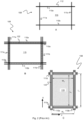
- Figs. 1A and 1C disclose a typical prior art automated storage and retrieval system 1 with a framework structure 100.
- Figs. 1B and 1D disclose a prior art container handling vehicle 200,300 operating the system 1 disclosed in Figs. 1A and 1C , respectively.
- the framework structure 100 comprises a plurality of upright members 102 and optionally a plurality of horizontal members 103 supporting the upright members 102.
- the members 102, 103 may typically be made of metal, e.g. extruded aluminum profiles.
- the framework structure 100 defines a storage grid 104 comprising storage columns 105 arranged in rows, in which storage columns 105 storage containers 106, also known as bins, are stacked one on top of another to form stacks 107.
- the container handling vehicles 300 may have a cantilever construction, as is described in NO317366 , the contents of which are also incorporated herein by reference.
- the container handling vehicles 200 may have a footprint, i.e. an extent in the X and Y directions, which is generally equal to the lateral extent of a grid cell 122, i.e. the extent of a grid cell 122 in the X and Y directions, e.g. as is described in WO2015/193278A1 , the contents of which are incorporated herein by reference.
- the term "lateral" used herein may mean "horizontal".
- the container handling vehicles 200 may have a footprint which is larger than the lateral extent of (lateral area defined by) a grid column 112, e.g. as is disclosed in WO2014/090684A1 .
- neighboring grid cells 122 are arranged in contact with each other such that there is no space there-between.
- a majority of the grid columns 112 are storage columns 105, i.e. grid columns 112 where storage containers 106 are stored in stacks 107.
- a grid 104 normally has at least one grid column 112 which is used not for storing storage containers 106, but which comprises a location where the container handling vehicles 200,300 can drop off and/or pick up storage containers 106 so that they can be transported to a second location (not shown) where the storage containers 106 can be accessed from outside of the grid 104 or transferred out of or into the grid 104.
- a location is normally referred to as a "port” and the grid column 112 in which the port is located may be referred to as a "delivery column" 119,120.
- the drop-off and pick-up ports of the container handling vehicles are referred to as the "upper ports of a delivery column" 119,120. While the opposite end of the delivery column is referred to as the "lower ports of a delivery column”.
- the second location may typically be a picking or a stocking station where product items are removed from or positioned into the storage containers 106.
- the storage containers 106 are normally never removed from the automated storage and retrieval system 1, but are returned into the storage grid 104 once accessed.
- there are also lower ports provided in a delivery column such lower ports are e.g. for transferring storage containers 106 to another storage facility (e.g. to another storage grid), directly to a transport vehicle (e.g. a train or a lorry), or to a production facility.
- the automated storage and retrieval system 1 For monitoring and controlling the automated storage and retrieval system 1 (e.g. monitoring and controlling the location of respective storage containers 106 within the storage grid 104; the content of each storage container 106; and the movement of the container handling vehicles 200,300 so that a desired storage container 106 can be delivered to the desired location at the desired time without the container handling vehicles 200,300 colliding with each other), the automated storage and retrieval system 1 comprises a control system (not shown) which typically is computerized and which typically comprises a database for keeping track of the storage containers 106.
- a conveyor system comprising conveyors may be employed to transport the storage containers between the lower port of the delivery column 119,120 and the access station.
- the conveyor system may comprise a lift device for transporting the storage containers 106 vertically between the port and the access station.
- the conveyor system may be arranged to transfer storage containers between different grids, e.g. as is described in WO2014/075937A1 , the contents of which are incorporated herein by reference.
- WO2016/198467A1 disclose an example of a prior art access system having conveyor belts (Figs. 5a and 5b in WO2016/198467A1 ) and a frame mounted rail ( Figs. 6a and 6b in WO2016/198467A1 ) for transporting storage containers between delivery columns and work stations where operators can access the storage containers.
- a problem associated with known automated storage and retrieval systems 1 is that the area surrounding the pick-up and drop-off ports may become congested with container handling vehicles 200,300 instructed to drop off or pick up storage containers 106. This may seriously impede the operation of the automated storage and retrieval system 1. In small systems this situation may possibly be alleviated by adding delivery columns to the grid, as this will allow the container handling vehicles 200,300 to be distributed among a larger number of ports of delivery columns in order to avoid congestion.
- the conveyor system infrastructure must normally be increased. This requires space, which may not necessarily be available. Also, adding conveyor system infrastructure is costly.
- Another problem with prior art automated storage and retrieval systems 1 is that the separate drop-off ports and pick-up ports of the delivery columns 119,120 require the container handling vehicles 200,300 to move to a storage column 105 after drop-off to retrieve a new storage container 106. Likewise, the container handling vehicles 200,300 have to be empty of a storage container 106 when they are sent to a pick-up port 120 to pick up a storage container. This results in an inefficiency and causes increased congestion around the ports, as container handling vehicles 200,300 are moving around on the grid without a storage container 106 as payload. In addition, the delivery columns 119,120 may take up space on the grid 104 which could be used for other purposes such as the movement of container handling vehicles 200,300.
- a robot device comprising a movable arm with a picking mechanism in one end thereof, for moving product items between storage containers 106.
- the robot device can be fixed to the grid or it can be fixed to the ceiling of the building in which the grid is located.
- the robot device in this prior art is used to move product items between storage containers 106 located on the top level of the grid and storage containers 106 located on a conveyor belt of a conveyor system.
- the area surrounding the robot device may become congested with container handling vehicles 200,300 instructed to drop off or pick up storage containers 106.
- adding conveyor system infrastructure is costly.
- GB 2544648 (Ocado Innovation) discloses an automated storage and retrieval system with a robot device for picking product items where the robot device is fixed to a robot vehicle, thereby forming a picking vehicle.
- Container handling vehicles are moved adjacent to this picking vehicle and the picking vehicle moves product items between the containers held by the container handling vehicles.
- the container handling vehicles comprise a top opening allowing the picking vehicle to access the container from above.
- One object of the invention is to provide a more efficient unloading of the containers in such automated storage and retrieval systems. This is typically achieved by reducing the distance the containers are transported and by reducing manual working operations. This can also be achieved by reducing space of equipment in the automated storage and retrieval system, as this typically will allow more container handling vehicles to operate in the system.
- an unloading arrangement comprising: a delivery vehicle; a storage container carried by the delivery vehicle; and an unloading station for unloading an item from the storage container while it is being carried by the delivery vehicle in an automatic storage and retrieval system, the unloading station comprising: an unloading device; and a destination conveyor configured to convey the item to a target destination, wherein the unloading device is configured to move the item through a side opening of the storage container to the destination conveyor.
- the container handling vehicle As an alternative to a delivery vehicle which carries storage containers above, it is possible to use the container handling vehicle with a cantilever construction (see Fig. 1D ).
- the unloading device When the storage container is in the uppermost position below the cantilever part, the unloading device may be used to move the item(s) through a side opening (on the relatively smaller side(s) of the storage container) to the destination conveyor.
- the storage container may comprise: a floor; a top opening; two first parallel side walls; and two side openings, one in each of the first parallel side walls.
- one side of the storage container may comprise two or more side openings.
- the different side openings may be separated by one or more structural element such as a vertical rod or beam or similar.
- the structural element(s) may e.g. be provided for increased rigidity, strength or stability of the storage container.
- each of the storage compartments may comprise one dedicated side opening.
- the storage container may have a rectangular shape where each of a pair of sides are parallel and of equal size.
- the side openings in the storage container may be arranged on two opposite sides, i.e. either on the two relatively largest sides or on the two relatively smaller sides.
- the storage containers may be of square shape, i.e. all four sides are of same size and both sides of each pair are parallel.
- storage containers both for rectangular and square shape, it may be arranged side openings on three or on all four sides of the storage container.
- the storage container will than comprise a floor, four vertical rods or beams in each of the four corners, and an upper portion for interaction with gripper(s) on the lifting frame of the container handling vehicle.
- the unloading device may comprise: a base structure; one or more unloading members, wherein each of the one or more unloading members has a contact surface; and one or more actuators configured to move the one or more unloading members.
- a method of unloading an item from a storage container comprising: carrying the storage container to an unloading station, the container being carried by a delivery vehicle; moving the item through a side opening of the storage container to a destination conveyor of the unloading station, the item being moved by an unloading device; conveying the item to a target destination.
- the storage container to be used in the method may comprise: a floor; a top opening; two first parallel side walls; and two side openings, one in each of the first parallel side walls.
- the unloading device to be used in the method may comprise: a base structure; one or more unloading members, wherein each of the one or more unloading members has a contact surface; and one or more actuators configured to move the one or more unloading members.
- the present invention also relates to a remotely operated delivery vehicle for transport of a storage container between an automated storage and retrieval grid configured to store a plurality of stacks of storage containers, and a second location for handling of the storage container by at least one of a robotic operator and a human operator,
- the second location is an unloading station comprising:
- each storage structure 1 constitutes a framework 100 of in total 143 grid columns 112, where the width and length of the framework corresponds to the width and length of 13 and 11 grid columns 112, respectively.
- the top layer of the framework 100 is a rail system 108 onto which a plurality of container handling vehicles 200,300 are operated.
- the framework 100 of the storage system 1 is constructed in accordance with the above mentioned prior art framework 100 described above, i.e. a plurality of upright members 102 and a plurality of horizontal members 103 which are supported by the upright members 102, and further that the horizontal members 103 includes a container handling vehicle rail system 108 of parallel rails 110,111 in the X direction and the Y direction, respectively, arranged across the top of storage columns 105.
- the horizontal area of a single grid cell 122 i.e. along the X and Y directions, may be defined by the distance between adjacent rails 110 and 111, respectively (see also Fig. 2 ). In Figs. 1A and 1C , such a grid cell 122 is marked on the rail system 108 by thick lines.
- the container handling vehicle rail system 108 allows the container handling vehicles 200,300 to move horizontally between different grid locations, where each grid location is associated with a grid cell 122.
- the storage grid 104 is shown with a height of eight cells. It is understood, however, that the storage grid 104 can in principle be of any size. In particular it is understood that storage grid 104 can be considerably wider and/or longer than disclosed in Figs. 1A and 1C .
- the grid 104 may have a horizontal extent of more than 700x700 grid cells 122.
- the grid 104 can be considerably deeper than disclosed in Figs. 1A and 1C .
- the storage grid 104 may be more than twelve grid cells deep.
- the storage container vehicles 200,300 may be of any type known in the art, e.g. any one of the automated container handling vehicles disclosed in WO2014/090684 A1 , in NO317366 or in WO2015/193278A1 .
- the rail system 108 may be a single track system, as is shown in Fig. 2A , a double track system, as is shown in Fig. 2B , or a combination of the single and double track systems. Details of the various track systems are disclosed this specification under the section of background and prior art.
- a control system of the automated storage and retrieval system 1 is shown as a box 20 provided in communication with the vehicles 200, 300.
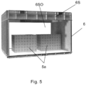
- the unloading station 10 comprises an unloading device generally indicated with arrow 40 and a destination conveyor generally indicated with arrow 60.
- the delivery vehicle 30 comprises a container carrier 36 located above the wheel arrangement 32. It should be noted that the delivery vehicle 30 in the present embodiment is different from the above vehicles 200, 300 in that the vehicle 30 itself does not comprise a lifting device for lowering and elevating a storage container with respect to the grid 104. In the present embodiment, the vehicle 30 is of a type adapted to receive a storage container 6 from above or to return a storage container 6 upwardly - by means of a separate lifting device.
- the lifting device used for this operation can for example be a lifting device of the prior art vehicles 200, 300, provided that the vehicle 30 is located below one of the vehicles 200, 300. Another example of such a lifting device will also be described further in detail below.
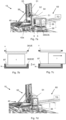
- the unloading device 40 further comprises a first actuator 44a configured to move the first unloading member 42a in relation to the base structure 41 and a second actuator 44b configured to move the second unloading member 42b in relation to the base structure 41.
- Fig. 6b the vehicle 30 has stopped at an unloading position between the destination conveyor 60 and the unloading device 40.
- One advantage of the unloading station 10 of the first embodiment described above is that it is relatively simple.
- One small disadvantage with the first embodiment may be that there is a risk that items 5 may slide out through the side openings 6SO, 36SO during acceleration and deceleration, in particular in the Y-direction shown in fig. 6b . This can be avoided by keeping the acceleration and deceleration of the vehicle 30 relatively low.
- Another way of overcoming this advantage is to provide the floor 6F of the storage container 6 with a material which increases the friction between the floor 6F and the items 5.
- the second embodiment described below provides yet an alternative solution to this disadvantage.
- the unloading station 10 is here similar to the unloading station 10 of the first embodiment, and only the differences will be described herein in detail.
- the lower edge 36SOE of the side opening 36SO is not horizontally aligned with the floor 6F of the storage container 6 when the storage container 6 is provided in the container carrier 36. Instead, the lower edge 36SOE of the side opening 36SO is provided at a height H1 above the floor 6F of the storage container 6, as shown in Fig. 7b . In this way, if the item 5 provided in the storage container 6 are sliding due to acceleration and deceleration of the vehicle 30, the lower edge 36SOE will prevent the item 5 from sliding further out through of the side opening 36SO of the container carrier 36.
- another object of the invention is solved in that it is avoided that product items fall out of the container during shipping or transportation of the container.
- the unloading station 10 comprises a container lifting device 50 for lifting of the storage container 6 up from the vehicle 30.
- the lifting height of the storage container 6 corresponds to the height H1, i.e. the container lifting device 50 is configured to lift the storage container 6 till a height where the floor 6F of the storage container 6 is horizontally aligned with the lower edge 36SOE of the side opening 36SO.
- the item 5 can be easily pushed out through the side openings 6SO and 36SO by means of the unloading device 40.
- the container lifting device 50 comprises a first frame structure 51 fixed to the base structure 41 of the unloading device 40 and protruding upwardly with respect to the grid 104. It should be noted that in an alternative embodiment, the first frame structure 51 could be fixed to the grid 104 or to another fixed structure close to the unloading device 40.
- the container lifting device 50 comprises a container lifting frame 54 with a connection interface CI for connection to and disconnection from the storage container 6.
- the container lifting frame 54 is of the same type of the container lifting frame 354 of container handling vehicle 300 shown in Fig. 1D .
- the container lifting frame 54 is fixed below a second frame structure 52, where the second frame structure 52 is movable up and down in relation to the first frame structure 51 by means of a lifting mechanism 53.
- the lifting mechanism 53 may be an electric motor, a linear electric or electrohydraulic actuator etc.
- the height of the unloading members 42a, 42b above the grid 104 may be adapted to the height of the lower edge 36SOE of the side opening 36SO by increasing the height of the base structure 41. Also, the height of the destination conveyor 60 may be adapted to the height of the lower edge 36SOE.
- Fig. 7a the vehicle 30 with a storage container 6 containing one item 5 is controlled by the control system 20 to move to the unloading station 10.
- Fig. 7d the vehicle 30 has stopped at an unloading position between the destination conveyor 60 and the unloading device 40.
- the lifting frame 54 is here in an elevated position.
- the unloading station 10 is here similar to the unloading station 10 of the second embodiment, and only the differences will be described herein in detail.
- the container carrier 36 of the vehicle 30 is not provided with openings.
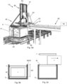
- the storage container 6 is lifted to a height H2 as indicated in Fig. 8b and Fig. 8f by means of the container lifting device 50, in order to horizontally align the floor 6F of the storage container 6 with an upper edge 36UE of the container carrier 36, as shown in Fig. 8c .
- the container lifting device 50 in order to horizontally align the floor 6F of the storage container 6 with an upper edge 36UE of the container carrier 36, as shown in Fig. 8c .
- the height of the unloading members 42a, 42b above the grid 104 are adapted to the height of the upper edge 36UE by increasing the height of the base structure 41. Also the height of the first frame structure 51 and the second frame structure 52 are changed due to the different lifting height H2 of the present embodiment. Also the height of the destination conveyor 60 has been adapted to the height of the upper edge 36UE.
- Fig. 8d the vehicle 30 has stopped at an unloading position between the destination conveyor 60 and the unloading device 40.
- the lifting frame 54 is here in an elevated position.
- Fig. 8f the lifting frame 54 has lifted the storage container upwardly a height H2, corresponding to Fig. 7c .
- lifting frame 54 will be lowered and the connection interface CI will be disconnected from the storage container 6.
- the vehicle 30 may move away from the unloading station 10.
- the destination conveyor 60 will move the item 5 to its target destination TD.
- Fig. 9a and 9b This embodiment corresponds to the first embodiment, i.e. the unloading station 10 does not comprise a container lifting device 50. However, the floor 6F is here provided at a height H1 below the lower edge 36SOE of the side opening 36SO of the container carrier 36, as in the second embodiment.
- the storage container 6 comprises an inclined member 6G provided between the floor 6F and the lower edge 36SOE, allowing the item 5 to be pushed by means of the unloading members 42a, 42b along the floor 6F and upwardly along the inclined member 6G and further out of the side opening 36SO, as shown in Fig. 9b .
- the unloading device 40 does not comprise a container lifting device 50 or unloading members 42.
- the unloading device 40 is provided as a tilting or pivoting device 48 mounted between the vehicle body 31 and the container carrier 36.
- the container carrier 36 can be tilted with a tilting angle TA with respect to horizontal plane.
- the tilting angle TA can for example be up to 60°. This will cause the item 5 to slide out from the container 6 and the container carrier 36 and onto the belt conveyor 61.
- the container carrier 36 is similar to the one in fig. 3 , where the lower edge 36SOE of the side opening 36SO is aligned with the floor 6F of the storage container 6 when the storage container 6 is provided in the container carrier 36.
- the container carrier 36 is similar to the one in fig. 9b , i.e. with an inclined member 6G provided between the floor 6F and the lower edge 36SOE.
- the container floor 6F may be manufactured of or may be equipped with a material providing a desired friction with respect to the item 5, to enable that the item slides out from the container 6 and the container carrier 36 at the desired location only.
- the unloading device 40 may comprise a combination of the fifth embodiment and the first embodiment, i.e. having both a tilting or pivoting device 48 provided on the vehicle 30 and one or more reciprocating unloading members 42.
- the delivery vehicle may comprise a weighing mechanism in order to measure the weight of the storage container, for example a commercially available electronic weighing scale.
- a weighing mechanism may provide information concerning the content inside each storage container such as the total weight, the number of units, the internal weight distribution and/or the location within the storage grid the storage container should be placed
- the automated storage and retrieval system 1 comprises a delivery system 140 provided partially below the storage grid 104.
- the delivery system 140 may further comprise a delivery rail system 150 with rails 151, 152.
- the rail system 150 can be of the same type as the rail system of the storage grid 104.
- the delivery rail system 150 shown in fig. 11 extends from a location inside the storage grid 104 to a location outside the storage grid 104, for example to a location where the above described unloading station 10 is located.
- the delivery vehicle 30 shown in fig. 11 can be one of the above described delivery vehicles.
- the delivery rails system 150 may be advantageous to arrange the delivery rails system 150 such that it extends as little as possible into the storage grid 104. That means that the storage and retrieval grid may comprise a plurality of storage columns extending from the upper level to the base of the storage grid, thus allowing the greatest possible storage capacity since the entire storage column may be used for storage.
- the part of the delivery rail system 150 extending into the storage grid may be kept as small as possible.
- the delivery rail system 150 and the delivery vehicle 30 may occupy as little space as possible of the storage and retrieval grid, the space which may be used for storage of storage containers.
- the delivery rail system 150 may comprise a first rail system located within the framework structure of the storage grid, and a second rail system located outside the framework structure of the storage grid, and wherein the first and second rail system are connected such that the delivery vehicle may operate between said rail systems.
- the delivery system 140 may comprise an interface connectable to a third-party storage, production and distribution system. This interface may be the delivery rail system
- the delivery system may be integrable with a third-party storage, production and distribution system such that storage containers can be transported between the delivery system and the third-party storage, production and distribution system.
- the delivery system of the present invention may be connectable to a third-party storage, production and distribution system such as production facility, a storage grid, assembling facility, reception or shipping location, etc.
- the connection may be by means of a connectable rail system or a conveyor system comprising conveyors employed to transport the storage containers between the delivery system and the third-party storage, production and distribution system.
Landscapes
- Engineering & Computer Science (AREA)
- Mechanical Engineering (AREA)
- Transportation (AREA)
- Physics & Mathematics (AREA)
- Structural Engineering (AREA)
- Automation & Control Theory (AREA)
- Aviation & Aerospace Engineering (AREA)
- General Physics & Mathematics (AREA)
- Mathematical Physics (AREA)
- Radar, Positioning & Navigation (AREA)
- Remote Sensing (AREA)
- Geology (AREA)
- Life Sciences & Earth Sciences (AREA)
- Civil Engineering (AREA)
- Human Computer Interaction (AREA)
- Warehouses Or Storage Devices (AREA)
Abstract
(5; 5a) from the storage container (6) while it is being carried by the delivery vehicle (30)
in an automatic storage and retrieval system (1), the unloading station comprising: an unloading device (40); and a destination conveyor (60) configured to convey the item to a target destination (TD), wherein the unloading device is configured to move the item through a side opening (6SO) of the storage container to the destination conveyor.
Description
- The present invention relates to an automated storage and retrieval system for storage and retrieval of containers, in particular to an unloading arrangement and an unloading station, as well as an associated method of unloading a product item from a container.
-
Figs. 1A and1C disclose a typical prior art automated storage andretrieval system 1 with aframework structure 100.Figs. 1B and1D disclose a prior art container handling vehicle 200,300 operating thesystem 1 disclosed inFigs. 1A and1C , respectively. - The
framework structure 100 comprises a plurality ofupright members 102 and optionally a plurality ofhorizontal members 103 supporting theupright members 102. Themembers - The
framework structure 100 defines astorage grid 104 comprisingstorage columns 105 arranged in rows, in whichstorage columns 105storage containers 106, also known as bins, are stacked one on top of another to formstacks 107. - Each
storage container 106 may typically hold a plurality of product items (not shown), and the product items within astorage container 106 may be identical, or may be of different product types depending on the application. - The
storage grid 104 guards against horizontal movement of thestorage containers 106 in thestacks 107, and guides vertical movement of thestorage containers 106, but does normally not otherwise support thestorage containers 106 when stacked. - The automated storage and
retrieval system 1 comprises a container handlingvehicle rail system 108 arranged in a grid pattern across the top of thestorage 104, on which rail system 108 a plurality of container handling vehicles 200,300 (as exemplified inFigs. 1B and1D ) are operated to raisestorage containers 106 from, andlower storage containers 106 into, thestorage columns 105, and also to transport thestorage containers 106 above thestorage columns 105. The horizontal extent of one of thegrid cells 122 constituting the grid pattern is inFigs. 1A and1C marked by thick lines. - Each
grid cell 122 has a width which is typically within the interval of 30 to 150 cm, and a length which is typically within the interval of 50 to 200 cm. Eachgrid opening 115 has a width and a length which is typically 2 to 10 cm less than the width and the length of thegrid cell 122 due to the horizontal extent of the rails 110,111. - The
rail system 108 comprises a first set ofparallel rails 110 arranged to guide movement of the container handling vehicles 200,300 in a first direction X across the top of theframe structure 100, and a second set ofparallel rails 111 arranged perpendicular to the first set ofrails 110 to guide movement of the container handling vehicles 200,300 in a second direction Y which is perpendicular to the first direction X. In this way, therail system 108 definesgrid columns 112 above which the container handling vehicles 200,300 can move laterally above thestorage columns 105, i.e. in a plane which is parallel to the horizontal X-Y plane. - Each prior art container handling vehicle 200,300 comprises a vehicle body and a wheel arrangement of eight wheels 201,301 where a first set of four wheels enable the lateral movement of the container handling vehicles 200,300 in the X direction and a second set of the remaining four wheels enable the lateral movement in the Y direction. One or both sets of wheels in the wheel arrangement can be lifted and lowered, so that the first set of wheels and/or the second set of wheels can be engaged with the respective set of
rails - Each prior art container handling vehicle 200,300 also comprises a lifting device (not shown) for vertical transportation of
storage containers 106, e.g. raising astorage container 106 from, and lowering astorage container 106 into, astorage column 105. The lifting device comprises one or more gripping / engaging devices (not shown) which are adapted to engage astorage container 106, and which gripping / engaging devices can be lowered from the vehicle 200,300 so that the position of the gripping / engaging devices with respect to the vehicle 200,300 can be adjusted in a third direction Z which is orthogonal the first direction X and the second direction Y. - Conventionally, and also for the purpose of this application, Z=1 identifies the uppermost layer of the
grid 104, i.e. the layer immediately below therail system 108, Z=2 the second layer below therail system 108, Z=3 the third layer etc. In the exemplaryprior art grid 104 disclosed inFigs. 1A and1C , Z=8 identifies the lowermost, bottom layer of thegrid 104. Consequently, as an example, and using the Cartesian coordinate system X, Y, Z indicated inFigs. 1A and1D , the storage container identified as 106' inFig. 1A can be said to occupy grid location or cell X=10, Y=2, Z=3. The container handling vehicles 200,300 can be said to travel in layer Z=0 and eachgrid column 112 can be identified by its X and Y coordinates. - Each
container handling vehicle 200 comprises a storage compartment or space (not shown) for receiving and stowing astorage container 106 when transporting thestorage container 106 across therail system 108. The storage space may comprise a cavity arranged centrally within the vehicle body, e.g. as is described inWO2014/090684A1 , the contents of which are incorporated herein by reference. - Alternatively, the
container handling vehicles 300 may have a cantilever construction, as is described inNO317366 - The container handling
vehicles 200 may have a footprint, i.e. an extent in the X and Y directions, which is generally equal to the lateral extent of agrid cell 122, i.e. the extent of agrid cell 122 in the X and Y directions, e.g. as is described inWO2015/193278A1 , the contents of which are incorporated herein by reference. The term "lateral" used herein may mean "horizontal". - Alternatively, the
container handling vehicles 200 may have a footprint which is larger than the lateral extent of (lateral area defined by) agrid column 112, e.g. as is disclosed inWO2014/090684A1 . - The
rail system 108 may be a single track system, as is shown inFig. 2A . Alternatively, therail system 108 may be a double track system, as is shown inFig. 2B , thus allowing acontainer handling vehicle 201 having a footprint 202,202' generally corresponding to the lateral area defined by agrid column 112 to travel along a row ofgrid columns 112 even if anothercontainer handling vehicle 200 is positioned above agrid column 112 neighboring that row. Both the single and double track system, or a combination comprising a single and double track arrangement in asingle rail system 108, forms a grid pattern in the horizontal plane P comprising a plurality of rectangular and uniform grid locations orgrid cells 122, where eachgrid cell 122 comprises agrid opening 115 being delimited by a pair ofrails first rails 110 and a pair of rails 11 1a,11 1b of the second set ofrails 111. InFig. 2B thegrid cell 122 is indicated by a dashed box. - Consequently,
rails rails - As shown in
Fig. 2C , eachgrid cell 122 has a width Wc which is typically within the interval of 30 to 150 cm, and a length Lc which is typically within the interval of 50 to 200 cm. Eachgrid opening 115 has a width Wo and a length Lo which is typically 2 to 10 cm less than the width Wc and the length Lc of thegrid cell 122. - In the X and Y directions, neighboring
grid cells 122 are arranged in contact with each other such that there is no space there-between. - In a
storage grid 104, a majority of thegrid columns 112 arestorage columns 105,i.e. grid columns 112 wherestorage containers 106 are stored instacks 107. However, agrid 104 normally has at least onegrid column 112 which is used not for storingstorage containers 106, but which comprises a location where the container handling vehicles 200,300 can drop off and/or pick upstorage containers 106 so that they can be transported to a second location (not shown) where thestorage containers 106 can be accessed from outside of thegrid 104 or transferred out of or into thegrid 104. Within the art, such a location is normally referred to as a "port" and thegrid column 112 in which the port is located may be referred to as a "delivery column" 119,120. The drop-off and pick-up ports of the container handling vehicles are referred to as the "upper ports of a delivery column" 119,120. While the opposite end of the delivery column is referred to as the "lower ports of a delivery column". - The
storage grids 104 inFigs. 1A and1C comprise twodelivery columns first delivery column 119 may for example comprise a dedicated drop-off port where the container handling vehicles 200,300 can drop offstorage containers 106 to be transported through thedelivery column 119 and further to an access or a transfer station (not shown), and thesecond delivery column 120 may comprise a dedicated pick-up port where the container handling vehicles 200,300 can pick upstorage containers 106 that have been transported through thedelivery column 120 from an access or a transfer station (not shown). Each of the ports of the first and second delivery column 119,120 may comprise a port suitable for both pick up and drop ofstorage containers 106. - The second location may typically be a picking or a stocking station where product items are removed from or positioned into the
storage containers 106. In a picking or a stocking station, thestorage containers 106 are normally never removed from the automated storage andretrieval system 1, but are returned into thestorage grid 104 once accessed. For transfer of storage containers out or into thestorage grid 104, there are also lower ports provided in a delivery column, such lower ports are e.g. for transferringstorage containers 106 to another storage facility (e.g. to another storage grid), directly to a transport vehicle (e.g. a train or a lorry), or to a production facility. - For monitoring and controlling the automated storage and retrieval system 1 (e.g. monitoring and controlling the location of
respective storage containers 106 within thestorage grid 104; the content of eachstorage container 106; and the movement of the container handling vehicles 200,300 so that a desiredstorage container 106 can be delivered to the desired location at the desired time without the container handling vehicles 200,300 colliding with each other), the automated storage andretrieval system 1 comprises a control system (not shown) which typically is computerized and which typically comprises a database for keeping track of thestorage containers 106. - A conveyor system comprising conveyors may be employed to transport the storage containers between the lower port of the delivery column 119,120 and the access station.
- If the lower port of the delivery column 119,120 and the access station are located at different levels, the conveyor system may comprise a lift device for transporting the
storage containers 106 vertically between the port and the access station. - The conveyor system may be arranged to transfer storage containers between different grids, e.g. as is described in
WO2014/075937A1 , the contents of which are incorporated herein by reference. - Further,
WO2016/198467A1 , the contents of which are incorporated herein by reference, disclose an example of a prior art access system having conveyor belts (Figs. 5a and 5b inWO2016/198467A1 ) and a frame mounted rail (Figs. 6a and 6b inWO2016/198467A1 ) for transporting storage containers between delivery columns and work stations where operators can access the storage containers. - When a
storage container 106 stored in thegrid 104 disclosed inFig. 1A is to be accessed, one of the container handling vehicles 200,300 is instructed to retrieve thetarget storage container 106 from its position in thegrid 104 and to transport it to or through thedelivery column 119. This operation involves moving the container handling vehicle 200,300 to a grid location above thestorage column 105 in which thetarget storage container 106 is positioned, retrieving thestorage container 106 from thestorage column 105 using the container handling vehicle's lifting device (not shown), and transporting thestorage container 106 to thedelivery column 119. If thetarget storage container 106 is located deep within astack 107, i.e. with one or a plurality of other storage containers positioned above thetarget storage container 106, the operation also involves temporarily moving the above-positioned storage containers prior to lifting thetarget storage container 106 from thestorage column 105. This step, which is sometimes referred to as "digging" within the art, may be performed with the same container handling vehicle 200,300 that is subsequently used for transporting thetarget storage container 106 to the delivery column, or with one or a plurality of other cooperating container handling vehicles 200,300. Alternatively, or in addition, the automated storage andretrieval system 1 may have container handling vehicles 200,300 specifically dedicated to the task of temporarily removingstorage containers 106 from astorage column 105. Once thetarget storage container 106 has been removed from thestorage column 105, the temporarily removed storage containers can be repositioned into theoriginal storage column 105. However, the removed storage containers may alternatively be relocated toother storage columns 105. - When a
storage container 106 is to be stored in thegrid 104, one of the container handling vehicles 200,300 is instructed to pick up thestorage container 106 from thedelivery column 120 and to transport it to a grid location above thestorage column 105 where it is to be stored. After any storage containers positioned at or above the target position within thestorage column stack 107 have been removed, the container handling vehicle 200,300 positions thestorage container 106 at the desired position. The removed storage containers may then be lowered back into thestorage column 105, or relocated toother storage columns 105. - A problem associated with known automated storage and
retrieval systems 1 is that the area surrounding the pick-up and drop-off ports may become congested with container handling vehicles 200,300 instructed to drop off or pick upstorage containers 106. This may seriously impede the operation of the automated storage andretrieval system 1. In small systems this situation may possibly be alleviated by adding delivery columns to the grid, as this will allow the container handling vehicles 200,300 to be distributed among a larger number of ports of delivery columns in order to avoid congestion. However, if ports and columns are added, the conveyor system infrastructure must normally be increased. This requires space, which may not necessarily be available. Also, adding conveyor system infrastructure is costly. - Another problem with prior art automated storage and
retrieval systems 1 is that the separate drop-off ports and pick-up ports of the delivery columns 119,120 require the container handling vehicles 200,300 to move to astorage column 105 after drop-off to retrieve anew storage container 106. Likewise, the container handling vehicles 200,300 have to be empty of astorage container 106 when they are sent to a pick-upport 120 to pick up a storage container. This results in an inefficiency and causes increased congestion around the ports, as container handling vehicles 200,300 are moving around on the grid without astorage container 106 as payload. In addition, the delivery columns 119,120 may take up space on thegrid 104 which could be used for other purposes such as the movement of container handling vehicles 200,300. - It is known, for example from
WO2016/198565 , to provide the above automated storage and retrieval system with a robot device comprising a movable arm with a picking mechanism in one end thereof, for moving product items betweenstorage containers 106. The robot device can be fixed to the grid or it can be fixed to the ceiling of the building in which the grid is located. The robot device in this prior art is used to move product items betweenstorage containers 106 located on the top level of the grid andstorage containers 106 located on a conveyor belt of a conveyor system. - Also here, the area surrounding the robot device may become congested with container handling vehicles 200,300 instructed to drop off or pick up
storage containers 106. Moreover, adding conveyor system infrastructure is costly. -
GB 2544648 (Ocado Innovation) - It is also known from the above publication that product items are picked from a container into a plurality of end-customer shipping packages located in the destination container. The destination container with these shipping packages is then transported to a port where the shipping packages are retrieved from the container, before they are closed, and possibly addressed and stamped. This is typically a manual operation.
- One object of the invention is to provide a more efficient unloading of the containers in such automated storage and retrieval systems. This is typically achieved by reducing the distance the containers are transported and by reducing manual working operations. This can also be achieved by reducing space of equipment in the automated storage and retrieval system, as this typically will allow more container handling vehicles to operate in the system.
- It is described an unloading arrangement comprising: a delivery vehicle; a storage container carried by the delivery vehicle; and an unloading station for unloading an item from the storage container while it is being carried by the delivery vehicle in an automatic storage and retrieval system, the unloading station comprising: an unloading device; and a destination conveyor configured to convey the item to a target destination, wherein the unloading device is configured to move the item through a side opening of the storage container to the destination conveyor.
- As an alternative to a delivery vehicle which carries storage containers above, it is possible to use the container handling vehicle with a cantilever construction (see
Fig. 1D ). When the storage container is in the uppermost position below the cantilever part, the unloading device may be used to move the item(s) through a side opening (on the relatively smaller side(s) of the storage container) to the destination conveyor. The storage container may comprise: a floor; a top opening; two first parallel side walls; and two side openings, one in each of the first parallel side walls. - The delivery vehicle may comprise a container carrier, wherein the container carrier may comprise: a carrier floor; a carrier top opening; two first carrier parallel side walls; two second carrier parallel side walls; two carrier side openings, one in each of the first carrier parallel side walls, each of the carrier side openings comprising a lower edge and an upper edge.
- The purpose of the unloading device is to move the item through the side opening of the storage container and through the side opening of the container carrier and further to the destination conveyor. If the delivery vehicle does not have a dedicated container carrier with side walls etc, the purpose of the unloading device is to move the item through the side opening of the storage container only and onto the destination conveyor.
- The side opening(s) in the storage container may be as large as practically possible, and may span over the whole width of the side of the storage container. The height of the side opening may extend as far as possible without affecting the upper portion of the storage container, which upper portion is arranged to interact with gripper(s) on lifting frame of the container handling vehicle.
- Alternatively, one side of the storage container may comprise two or more side openings. The different side openings may be separated by one or more structural element such as a vertical rod or beam or similar. The structural element(s) may e.g. be provided for increased rigidity, strength or stability of the storage container. In addition, if the storage container is divided into two or more separate storage compartments, each of the storage compartments may comprise one dedicated side opening.
- The storage container may have a rectangular shape where each of a pair of sides are parallel and of equal size. The side openings in the storage container may be arranged on two opposite sides, i.e. either on the two relatively largest sides or on the two relatively smaller sides.
- Alternatively, the storage containers may be of square shape, i.e. all four sides are of same size and both sides of each pair are parallel.
- In either case of storage containers, both for rectangular and square shape, it may be arranged side openings on three or on all four sides of the storage container. The storage container will than comprise a floor, four vertical rods or beams in each of the four corners, and an upper portion for interaction with gripper(s) on the lifting frame of the container handling vehicle. An advantage of storage containers with side openings, and in particular if the storage container has a square shape, is that they are not dependent on a specific orientation during lifting, transport and/or unloading.
- The unloading device may comprise: a base structure; one or more unloading members, wherein each of the one or more unloading members has a contact surface; and one or more actuators configured to move the one or more unloading members.
- The one or more unloading members may comprise: a first unloading member having a first contact surface adapted to the item; and a second unloading member having a second contact surface adapted to the item.
- The one or more actuators may comprise: a first actuator configured to move the first unloading member; and a second actuator configured to move the second unloading member.
- The actuators may be configured to move the unloading members independently.
- The unloading device may further comprise a container lifting device which may comprise: a first frame structure; a container lifting frame having a connection interface configured to connect to the container; and a lifting mechanism configured to lift the container lifting frame relative to the first frame structure.
- Alternatively, the unloading device may be provided as a tilting or pivoting device mounted between the vehicle body and the container carrier. In this way, the item may slide out from the container and container carrier and further onto the conveying device.
- The container lifting device may further comprise a second frame structure, wherein the container lifting frame may be fixed below the second frame structure, and wherein the lifting mechanism may be configured to move the second frame structure up and down relative to the first frame structure.
- The container lifting device may be configured to lift the container to a height where the floor of the storage container is horizontally aligned with the lower edge of the side opening.
- As the lower edge of the side opening in the container carrier is preferably horizontally aligned with the floor of the storage container when the storage container is provided in the container carrier, the item can easily be pushed out through the side openings.
- The automated storage and retrieval system may comprise a storage grid and the base structure can be fixed to the storage grid.
- It is described an unloading station for unloading an item from a storage container while it is being carried by a delivery vehicle in an automatic storage and retrieval system, the unloading station may comprise: a rail system comprising a plurality of rails defining an arrangement of grid cells; an unloading device arranged on one side of a grid cell; and a destination conveyor arranged on an opposite side of a grid cell and configured to convey the item to a target destination, wherein the unloading device is configured to move the item through a side opening of the storage container to the destination conveyor.
- It is described a method of unloading an item from a storage container, the method comprising: carrying the storage container to an unloading station, the container being carried by a delivery vehicle; moving the item through a side opening of the storage container to a destination conveyor of the unloading station, the item being moved by an unloading device; conveying the item to a target destination.
- The storage container to be used in the method may comprise: a floor; a top opening; two first parallel side walls; and two side openings, one in each of the first parallel side walls.
- The unloading device to be used in the method may comprise: a base structure; one or more unloading members, wherein each of the one or more unloading members has a contact surface; and one or more actuators configured to move the one or more unloading members.
- The present invention also relates to a remotely operated delivery vehicle for transport of a storage container between an automated storage and retrieval grid configured to store a plurality of stacks of storage containers, and a second location for handling of the storage container by at least one of a robotic operator and a human operator,
- the remotely operated delivery vehicle comprising;
- rolling devices configured to move the remotely operated delivery vehicle in a horizontal plane along tracks of a delivery rail system comprising a first set of parallel rails arranged in a first direction and a second set of parallel rails arranged in a second direction orthogonal to the first direction,
- rolling device motors for driving the rolling devices and
- a power source configured to provide propulsion power to the rolling device motors,
- where the remotely operated delivery vehicle further comprises a container carrier configured to receive the storage container onto or at least partly into the container carrier;
- characterized in that the container carrier comprises:
- two first carrier parallel side walls;
- two second carrier parallel side walls;
- two carrier side openings, one in each of the first carrier parallel side walls, each of the carrier side openings comprising a lower edge and an upper edge.
- In one aspect, the second location is an unloading station comprising:
- an unloading device; and
- a destination conveyor;
- In one aspect, the lower edge of the carrier side openings is aligned with a floor of the storage container during movement of the item by means of the unloading device.
- The following drawings depict exemplary embodiments of the present invention and are appended to facilitate the understanding of the invention.
-
Fig. 1 A-D are perspectives view of a prior art automated storage and retrieval system, whereFig. 1A andFig. 1C shows the complete system andFig. 1B andFig. 1D shows examples of system operable prior art container handling vehicles. -
Fig. 2 A-C is a top view of a container handling vehicle rail system, whereFig. 2A shows a single track system,Fig. 2B shows a double track system 2B andFig. 2 C shows a double track system indicated width and length of a container handling vehicle grid cell. -
Fig. 3 and 4 are perspective views of a first embodiment of the present invention - inFig. 3 the container is carried by a delivery vehicle while inFig. 4 the container is shown isolated from the delivery vehicle. -
Fig. 5 is an enlarged view of the container containing two shipping packages. -
Fig. 6a-d show the operation of the first embodiment. -
Fig. 7a-g show the operation of a second embodiment. -
Fig. 8a-h show the operation of a third embodiment. -
Fig. 9a and 9b show an alternative embodiment. -
Fig. 10a, 10b and 10c show yet an alternative embodiment. -
Fig. 11 shows a storage grid with a delivery system. - In the following, embodiments of the invention will be discussed in more detail with reference to the appended drawings. It should be understood, however, that the drawings are not intended to limit the invention to the subject-matter depicted in the drawings. Furthermore, even if some of the features are described in relation to the system only, it is apparent that they are valid for the delivery vehicles and related methods as well, and vice versa. Hence, any features described in relation to the delivery vehicle only, and/or related methods, are also valid for the system.
- With reference to
Figs. 1A-D thestorage grid 104 of eachstorage structure 1 constitutes aframework 100 of in total 143grid columns 112, where the width and length of the framework corresponds to the width and length of 13 and 11grid columns 112, respectively. The top layer of theframework 100 is arail system 108 onto which a plurality of container handling vehicles 200,300 are operated. - The
framework 100 of thestorage system 1 is constructed in accordance with the above mentionedprior art framework 100 described above, i.e. a plurality ofupright members 102 and a plurality ofhorizontal members 103 which are supported by theupright members 102, and further that thehorizontal members 103 includes a container handlingvehicle rail system 108 of parallel rails 110,111 in the X direction and the Y direction, respectively, arranged across the top ofstorage columns 105. The horizontal area of asingle grid cell 122, i.e. along the X and Y directions, may be defined by the distance betweenadjacent rails Fig. 2 ). InFigs. 1A and1C , such agrid cell 122 is marked on therail system 108 by thick lines. - The container handling
vehicle rail system 108 allows the container handling vehicles 200,300 to move horizontally between different grid locations, where each grid location is associated with agrid cell 122. - In
Figs. 1A and1C thestorage grid 104 is shown with a height of eight cells. It is understood, however, that thestorage grid 104 can in principle be of any size. In particular it is understood thatstorage grid 104 can be considerably wider and/or longer than disclosed inFigs. 1A and1C . For example, thegrid 104 may have a horizontal extent of more than700x700 grid cells 122. Also, thegrid 104 can be considerably deeper than disclosed inFigs. 1A and1C . For example, thestorage grid 104 may be more than twelve grid cells deep. - The storage container vehicles 200,300 may be of any type known in the art, e.g. any one of the automated container handling vehicles disclosed in
WO2014/090684 A1 , inNO317366 WO2015/193278A1 . - The
rail system 108 may be a single track system, as is shown inFig. 2A , a double track system, as is shown inFig. 2B , or a combination of the single and double track systems. Details of the various track systems are disclosed this specification under the section of background and prior art. - In
fig. 1A , a control system of the automated storage andretrieval system 1 is shown as abox 20 provided in communication with thevehicles - It is now referred to
Fig. 3 and 4 . Here, it is shown an unloadingstation 10 for an automated storage andretrieval system 1. - The unloading
station 10 comprises an unloading device generally indicated witharrow 40 and a destination conveyor generally indicated witharrow 60. - It is also shown a remotely operated vehicle in the form of a
delivery vehicle 30. Thedelivery vehicle 30 comprises avehicle body 31 and awheel arrangement 32 connected to thevehicle body 31. Thewheel arrangement 32 is configured to move the remotely operatedvehicle 30 along therail system 108 of the automated storage andretrieval system 1 or along a correspondingrail system 108 located below or adjacent to thegrid 104. Thewheel arrangement 32 is considered to be prior art and will not be described further in detail herein. - The
delivery vehicle 30 comprises acontainer carrier 36 located above thewheel arrangement 32. It should be noted that thedelivery vehicle 30 in the present embodiment is different from theabove vehicles vehicle 30 itself does not comprise a lifting device for lowering and elevating a storage container with respect to thegrid 104. In the present embodiment, thevehicle 30 is of a type adapted to receive astorage container 6 from above or to return astorage container 6 upwardly - by means of a separate lifting device. The lifting device used for this operation can for example be a lifting device of theprior art vehicles vehicle 30 is located below one of thevehicles - In the present embodiment, the
container carrier 36 comprises two first parallel side walls 36S1 each having a side opening 36SO and two second parallel side walls 36S2 perpendicular to the first side walls 36S1. The two second sidewalls 36S2 do not have side openings. In addition, the container carrier comprises afloor 36F and a top opening 36TO for receiving and delivering astorage container 6. In the present embodiment, a lower edge 36SOE of the side opening 36SO is horizontally aligned with thefloor 6F of thestorage container 6 when thestorage container 6 is provided in thecontainer carrier 36. - The
storage container 6 is here similar to the priorart storage containers 106 described above, with one difference - thestorage container 6 comprises two side openings 6SO in its two first parallel side walls 6S1. As shown inFig. 4 , the storage container has afloor 6F and a top opening 6TO. - The
unloading device 40 will now be described. Theunloading device 40 comprises abase structure 41 which may be fixed togrid 104 or to therail system 108. Theunloading device 40 further comprises afirst unloading member 42a having afirst contact surface 43a and asecond unloading member 42b having asecond contact surface 43b. The contact surfaces 43a, 43b are adapted to theitem 5. For the planar cardboard box inFig. 3 , the contact surfaces 43a, 43b are planar. - The
unloading device 40 further comprises afirst actuator 44a configured to move thefirst unloading member 42a in relation to thebase structure 41 and asecond actuator 44b configured to move thesecond unloading member 42b in relation to thebase structure 41. - In addition, the
unloading device 40 comprises a control system for controlling the first and/orsecond actuator control system 20 of the automated storage andretrieval system 1 shown inFig. 1 , which is also controlling the movement of the vehicles with respect to theunloading device 40. - It should be noted that there can be one such unloading member 42 or there can be three or more such unloading members 42. In an automated storage and
retrieval system 1, there may be severalsuch unloading stations 10, where some unloadingstations 10 have one unloading member 42 to be used forlarger items 5, while other unloadingstations 10 have several unloading members 42 to be used forsmaller items 5. Moreover, thecontact surface 43 of some unloading members 42 may be designed for one specific type ofitem 5. - It should also be noted that the
unloading members Fig. 3 may be moved in parallel when unloading larger items and may be moved one by one when unloading smaller items. - The purpose of the
unloading device 40 is to move anitem 5 stored in thestorage container 6 through the side opening 36SO of thecontainer carrier 36 and through the side opening 6SO of thestorage container 6 and further to thedestination conveyor 60. As the lower edge 36SOE of the side opening 36SO is horizontally aligned with thefloor 6F of thestorage container 6 when thestorage container 6 is provided in thecontainer carrier 36, theitem 5 can easily be pushed out through the side openings 6SO and 36SO. - In the first embodiment, the first and
second actuators unloading members - The
destination conveyor 60 will now be described. Thedestination conveyor 60 here comprises abelt conveyor 61 which in one ends receives anitem 5 and conveys it to its second end, which hereinafter is referred to as a target destination TD. - In
Fig. 3 , anitem 5 in the form of a shipping package containing twoproduct items 5a is shown at the target destination TD. Here, before arrival to the unloadingstation 10,product items 5a have been picked fromstorage containers 106 stored in thegrid 104 into theshipping package 5 provided in thestorage container 6, which then has been transferred to the unloadingstation 10 by means of thevehicle 30 for unloading of the shipping package to thedestination conveyor 60. - It should be noted that the
shipping package 5 here is a cardboard box which is one example of a shipping package which may be used to shipproduct items 5a. Other examples of such shipping packages are boxes or bags made of plastic or paper, lined envelopes etc. The unloadingstation 10 can be used independent of how the product items were picked into the shipping packages, the picking operation may be an automated picking process or a manual picking process. Hence, in some cases, no picking operation takes place before thestorage container 6 is moved to the unloading station. - It should also be mentioned that some
product items 5a do not need afurther shipping package 5 before shipping. One such example is shown inFig. 5 . Here, twoproduct items 5a have been prepackaged into respective shipping packages and stored in astorage container 6 and/orstorage container 106 before arrival into the automated storage and retrieval system. Here, theproduct items 5a may be unloaded directly from thestorage container 6 to the destination conveyor. Hence, the term "item" is here referring to bothproduct items 5a andshipping packages 5 containing one or severalsuch product items 5a. - Is should be noted that the
destination conveyor 60 may comprise a roller conveyor or other types of conveying means for conveying the item to the target destination TD. Moreover, it should be noted that the target destination TD is the target destination of the unloadingstation 10. Theitem 5 may be transferred to further destinations, for example a station where the shipping packages are closed, addressed and/or prepared for dispatch by postal services or delivery services, to pickup points etc. - In
Fig. 3 , the distance D between the contact surfaces 43a, 43b in their deactivated position and thedestination conveyor 60 is slightly larger than the width W of thevehicle 30, thereby allowing thevehicle 30 to move between thedestination conveyor 60 and theunloading device 40 while at the same time helping to avoiditems 5 being able to fall onto the floor below the unloadingstation 10. - In addition, the height of the
belt conveyor 61 is aligned with the height of thefloor 6F of thestorage container 6. - The operation of the unloading
station 10 will now be described. InFig. 6a , thevehicle 30 with astorage container 6 containing oneitem 5 is controlled by thecontrol system 20 to move to the unloadingstation 10. - In
Fig. 6b , thevehicle 30 has stopped at an unloading position between thedestination conveyor 60 and theunloading device 40. - In
Fig. 6c , theunloading members item 5 out from thestorage container 6 and thecontainer carrier 36 and onto thebelt conveyor 61. - In
Fig. 6d , theunloading members item 5 towards its target destination TD. - Then, in a final step shown in
Fig. 3 , thevehicle 30 is moving away from the unloadingstation 10 and theitem 5 has reached its target destination TD. - One advantage of the unloading
station 10 of the first embodiment described above is that it is relatively simple. One small disadvantage with the first embodiment may be that there is a risk thatitems 5 may slide out through the side openings 6SO, 36SO during acceleration and deceleration, in particular in the Y-direction shown infig. 6b . This can be avoided by keeping the acceleration and deceleration of thevehicle 30 relatively low. Another way of overcoming this advantage is to provide thefloor 6F of thestorage container 6 with a material which increases the friction between thefloor 6F and theitems 5. The second embodiment described below provides yet an alternative solution to this disadvantage. - It is now referred to
Fig. 7a, 7b and 7c . The unloadingstation 10 is here similar to the unloadingstation 10 of the first embodiment, and only the differences will be described herein in detail. - In the present embodiment, the lower edge 36SOE of the side opening 36SO is not horizontally aligned with the
floor 6F of thestorage container 6 when thestorage container 6 is provided in thecontainer carrier 36. Instead, the lower edge 36SOE of the side opening 36SO is provided at a height H1 above thefloor 6F of thestorage container 6, as shown inFig. 7b . In this way, if theitem 5 provided in thestorage container 6 are sliding due to acceleration and deceleration of thevehicle 30, the lower edge 36SOE will prevent theitem 5 from sliding further out through of the side opening 36SO of thecontainer carrier 36. Thus, another object of the invention is solved in that it is avoided that product items fall out of the container during shipping or transportation of the container. - In the present embodiment, the unloading
station 10 comprises acontainer lifting device 50 for lifting of thestorage container 6 up from thevehicle 30. As shown inFig. 7c , the lifting height of thestorage container 6 corresponds to the height H1, i.e. thecontainer lifting device 50 is configured to lift thestorage container 6 till a height where thefloor 6F of thestorage container 6 is horizontally aligned with the lower edge 36SOE of the side opening 36SO. In the lifted position shown inFig. 7c , theitem 5 can be easily pushed out through the side openings 6SO and 36SO by means of theunloading device 40. - In
Fig. 7a , it is shown that thecontainer lifting device 50 comprises afirst frame structure 51 fixed to thebase structure 41 of theunloading device 40 and protruding upwardly with respect to thegrid 104. It should be noted that in an alternative embodiment, thefirst frame structure 51 could be fixed to thegrid 104 or to another fixed structure close to theunloading device 40. - The
container lifting device 50 comprises acontainer lifting frame 54 with a connection interface CI for connection to and disconnection from thestorage container 6. In the present embodiment, thecontainer lifting frame 54 is of the same type of thecontainer lifting frame 354 ofcontainer handling vehicle 300 shown inFig. 1D . Thecontainer lifting frame 54 is fixed below asecond frame structure 52, where thesecond frame structure 52 is movable up and down in relation to thefirst frame structure 51 by means of alifting mechanism 53. Thelifting mechanism 53 may be an electric motor, a linear electric or electrohydraulic actuator etc. - In the present embodiment, the height of the
unloading members grid 104 may be adapted to the height of the lower edge 36SOE of the side opening 36SO by increasing the height of thebase structure 41. Also, the height of thedestination conveyor 60 may be adapted to the height of the lower edge 36SOE. - The operation of the unloading
station 10 will now be described. InFig. 7a , thevehicle 30 with astorage container 6 containing oneitem 5 is controlled by thecontrol system 20 to move to the unloadingstation 10. - In
Fig. 7d , thevehicle 30 has stopped at an unloading position between thedestination conveyor 60 and theunloading device 40. The liftingframe 54 is here in an elevated position. - In
Fig. 7e , the liftingframe 54 has been lowered and the connection interface CI is connected to thestorage container 6. - In
Fig. 7f , the liftingframe 54 has lifted the storage container upwardly a height H1, corresponding toFig. 7c . - In
Fig. 7g , theunloading members item 5 out from thestorage container 6 and thecontainer carrier 36 and onto thebelt conveyor 61. - When the
item 5 has been pushed out and onto thedestination conveyor 60, theunloading members frame 54 will be lowered and the connection interface CI will be disconnected from thestorage container 6. After elevating the liftingframe 54 without thestorage container 6, thevehicle 30 may move away from the unloadingstation 10. As described above, thedestination conveyor 60 will move theitem 5 to its target destination TD. - It is now referred to
Fig. 8a, 8b and 8c . The unloadingstation 10 is here similar to the unloadingstation 10 of the second embodiment, and only the differences will be described herein in detail. - In the present embodiment, the
container carrier 36 of thevehicle 30 is not provided with openings. Here, thestorage container 6 is lifted to a height H2 as indicated inFig. 8b andFig. 8f by means of thecontainer lifting device 50, in order to horizontally align thefloor 6F of thestorage container 6 with an upper edge 36UE of thecontainer carrier 36, as shown inFig. 8c . In this way, if theitem 5 provided in thestorage container 6 are sliding due to acceleration and deceleration of thevehicle 30, theitem 5 will not fall out of thestorage container 6 as there are no side openings in thecontainer carrier 36. - In the present embodiment, the height of the
unloading members grid 104 are adapted to the height of the upper edge 36UE by increasing the height of thebase structure 41. Also the height of thefirst frame structure 51 and thesecond frame structure 52 are changed due to the different lifting height H2 of the present embodiment. Also the height of thedestination conveyor 60 has been adapted to the height of the upper edge 36UE. - The operation of the unloading
station 10 will now be described. InFig. 8a , thevehicle 30 with astorage container 6 containing oneitem 5 is controlled by thecontrol system 20 to move to the unloadingstation 10. - In
Fig. 8d , thevehicle 30 has stopped at an unloading position between thedestination conveyor 60 and theunloading device 40. The liftingframe 54 is here in an elevated position. - In
Fig. 8e , the liftingframe 54 has been lowered and the connection interface CI is connected to thestorage container 6. - In
Fig. 8f , the liftingframe 54 has lifted the storage container upwardly a height H2, corresponding toFig. 7c . - In
Fig. 8g , theunloading members item 5 out from thestorage container 6 and onto thebelt conveyor 61. - In
Fig. 8h , theunloading members - Later, lifting
frame 54 will be lowered and the connection interface CI will be disconnected from thestorage container 6. After elevating the liftingframe 54 without thestorage container 6, thevehicle 30 may move away from the unloadingstation 10. As described above, thedestination conveyor 60 will move theitem 5 to its target destination TD. - It is now referred to
Fig. 9a and 9b . This embodiment corresponds to the first embodiment, i.e. the unloadingstation 10 does not comprise acontainer lifting device 50. However, thefloor 6F is here provided at a height H1 below the lower edge 36SOE of the side opening 36SO of thecontainer carrier 36, as in the second embodiment. - Here, the
storage container 6 comprises aninclined member 6G provided between thefloor 6F and the lower edge 36SOE, allowing theitem 5 to be pushed by means of theunloading members floor 6F and upwardly along theinclined member 6G and further out of the side opening 36SO, as shown inFig. 9b . - The embodiments described in relation to the Figures solve at least some of the objectives, including that product items and shipping packages are handled with care - i.e. they are not damaged during the unloading of the container.
- It is now referred to
fig. 10a . Here, theunloading device 40 does not comprise acontainer lifting device 50 or unloading members 42. Here, theunloading device 40 is provided as a tilting or pivotingdevice 48 mounted between thevehicle body 31 and thecontainer carrier 36. Infig. 10 , it is shown that thecontainer carrier 36 can be tilted with a tilting angle TA with respect to horizontal plane. The tilting angle TA can for example be up to 60°. This will cause theitem 5 to slide out from thecontainer 6 and thecontainer carrier 36 and onto thebelt conveyor 61. - In
fig. 10b , thecontainer carrier 36 is similar to the one infig. 3 , where the lower edge 36SOE of the side opening 36SO is aligned with thefloor 6F of thestorage container 6 when thestorage container 6 is provided in thecontainer carrier 36. - In
fig. 10c , thecontainer carrier 36 is similar to the one infig. 9b , i.e. with aninclined member 6G provided between thefloor 6F and the lower edge 36SOE. - It should be noted that in this and other embodiments above, the
container floor 6F may be manufactured of or may be equipped with a material providing a desired friction with respect to theitem 5, to enable that the item slides out from thecontainer 6 and thecontainer carrier 36 at the desired location only. - It should also be noted that the
unloading device 40 may comprise a combination of the fifth embodiment and the first embodiment, i.e. having both a tilting or pivotingdevice 48 provided on thevehicle 30 and one or more reciprocating unloading members 42. - In the preceding description, it should be noted that the delivery vehicle may comprise a weighing mechanism in order to measure the weight of the storage container, for example a commercially available electronic weighing scale. Such a weighing mechanism may provide information concerning the content inside each storage container such as the total weight, the number of units, the internal weight distribution and/or the location within the storage grid the storage container should be placed
- It is now referred to
fig. 11 . Here, the automated storage andretrieval system 1 comprises adelivery system 140 provided partially below thestorage grid 104. Thedelivery system 140 may further comprise adelivery rail system 150 withrails rail system 150 can be of the same type as the rail system of thestorage grid 104. - The
delivery rail system 150 shown infig. 11 extends from a location inside thestorage grid 104 to a location outside thestorage grid 104, for example to a location where the above described unloadingstation 10 is located. Thedelivery vehicle 30 shown infig. 11 can be one of the above described delivery vehicles. - To get the most storage space for storage containers in the storage and retrieval grid, it may be advantageous to arrange the
delivery rails system 150 such that it extends as little as possible into thestorage grid 104. That means that the storage and retrieval grid may comprise a plurality of storage columns extending from the upper level to the base of the storage grid, thus allowing the greatest possible storage capacity since the entire storage column may be used for storage. - In order to maintain greatest possible storage capacity, the part of the
delivery rail system 150 extending into the storage grid may be kept as small as possible. Thus, thedelivery rail system 150 and thedelivery vehicle 30 may occupy as little space as possible of the storage and retrieval grid, the space which may be used for storage of storage containers. - The
delivery rail system 150 may comprise a first rail system located within the framework structure of the storage grid, and a second rail system located outside the framework structure of the storage grid, and wherein the first and second rail system are connected such that the delivery vehicle may operate between said rail systems. - The
delivery system 140 may comprise an interface connectable to a third-party storage, production and distribution system. This interface may be the delivery rail system - The delivery system may be integrable with a third-party storage, production and distribution system such that storage containers can be transported between the delivery system and the third-party storage, production and distribution system.
- The delivery system of the present invention may be connectable to a third-party storage, production and distribution system such as production facility, a storage grid, assembling facility, reception or shipping location, etc. The connection may be by means of a connectable rail system or a conveyor system comprising conveyors employed to transport the storage containers between the delivery system and the third-party storage, production and distribution system.
- In the preceding description, various aspects of the delivery vehicle and the automated storage and retrieval system according to the invention have been described with reference to the illustrative embodiment. For purposes of explanation, specific numbers, systems and configurations were set forth in order to provide a thorough understanding of the system and its workings. However, this description is not intended to be construed in a limiting sense. Various modifications and variations of the illustrative embodiment, as well as other embodiments of the system, which are apparent to persons skilled in the art to which the disclosed subject matter pertains, are deemed to lie within the scope of the present invention as defined by the appended claims.
-
- 1
- Automated storage and retrieval system
- 5
- item
- 5a
- Product item
- 6
- Storage container
- 6SO
- Side opening storage container
- 6F
- Floor of storage container
- 6S1
- First parallel side walls storage container
- 6TO
- Top opening storage container
- 10
- Unloading station
- 20
- Control system storage and retrieval system
- 30
- Delivery vehicle
- 31
- Vehicle body
- 32
- Wheel arrangement
- 36
- Container carrier
- 36F
- Floor of container carrier
- 36SO
- Side opening container carrier
- 3651
- First parallel side walls container carrier
- 3652
- Second parallel side walls container carrier
- 36TO
- Top opening container carrier
- 36SOE
- Lower edge side opening container carrier
- 36UE
- Upper edge container carrier
- 40
- Unloading device
- 41
- Base structure unloading device
- 42a
- First unloading member
- 42b
- Second unloading member
- 43a
- First contact surface of first unloading member
- 43b
- Second contact surface of unloading member
- 44a
- First actuator
- 44b
- Second actuator
- 48
- Tilting/pivoting device
- 50
- Container lifting device
- 51
- First frame structure
- 52
- Second frame structure
- 53
- Lifting mechanism
- 54
- Container lifting frame
- 60
- Destination conveyor
- 61
- Belt conveyor
- 100
- Framework structure
- 102
- Upright members of framework structure
- 103
- Horizontal members of framework structure
- 104
- Storage grid / three-dimensional grid
- 105
- Storage column
- 106
- Storage container
- 107
- Stack
- 108
- Rail system / Container handling vehicle rail system
- 110
- First set of parallel rails in first direction (X)
- 110a
- First neighboring rail of first set
- 110b
- Second neighboring rail of first set
- 111
- Second set of parallel rails in second direction (Y)
- 111a
- First neighboring rail of second set
- 111b
- Second neighboring rail of second set
- 115
- Grid opening / Container handling vehicle grid opening
- 119
- Delivery column
- 120
- Delivery column
- 122
- Grid cell / Container handling vehicle grid cell
- 140
- Delivery system
- 200
- First container handling vehicle
- 201
- Wheel arrangement
- 202,202'
- Container handling vehicle footprint
- 300
- Second container handling vehicle
- 301
- Wheel arrangement
- X
- First direction
- Y
- Second direction
- Wo
- Width of container handling vehicle grid opening
- Wc
- Width of container handling vehicle grid cell
- Lo
- Length of container handling vehicle grid opening
- Lc
- Length of container handling vehicle grid cell
- Wod
- Width of delivery vehicle grid opening
- Wcd
- Width of delivery vehicle grid cell
- Lod
- Length of delivery vehicle grid opening
- Lcd
- Length of delivery vehicle grid cell
- H1
- Height
- H2
- height
- TD
- Target destination
- CI
- Connection interface
- 1. An unloading arrangement comprising:
- a delivery vehicle (30);
- a storage container (6) carried by the delivery vehicle (30); and an unloading station (10) for unloading an item (5; 5a) from the storage container (6) while it is being carried by the delivery vehicle (30) in an automatic storage and retrieval system (1), the unloading station comprising:
- an unloading device (40); and
- a destination conveyor (60) configured to convey the item to a target destination (TD),
- wherein the unloading device is configured to move the item through a side opening (6SO) of the storage container to the destination conveyor.
- 2. The unloading arrangement of
item 1, wherein the storage container comprises:- a floor (6F);
- a top opening (6TO);
- two first parallel side walls (6S1); and
- two side openings (6SO), one in each of the first parallel side walls.
- 3. The unloading arrangement of
item - a carrier floor (36F);
- a carrier top opening (36TO);
- two first carrier parallel side walls (3651);
- two second carrier parallel side walls (3652);
- two carrier side openings (36SO), one in each of the first carrier parallel side walls, each of the carrier side openings comprising a lower edge (365OE) and an upper edge (36UE).
- 4. The unloading arrangement of any preceding item, wherein the unloading device comprises:
- a base structure (41);
- one or more unloading members (42a, 42b), wherein each of the one or more unloading members has a contact surface (43a, 43b); and
- one or more actuators (44a, 44b) configured to move the one or more unloading members.
- 5. The unloading arrangement of item 4, wherein the one or more unloading members comprises:
- a first unloading member (42a) having a first contact surface (43a) adapted to the item; and
- a second unloading member (42b) having a second contact surface (43b) adapted to the item.
- 6. The unloading arrangement of
item 5, wherein the one or more actuators comprises:- a first actuator (44a) configured to move the first unloading member; and
- a second actuator (44b) configured to move the second unloading member.
- 7. The unloading arrangement of
item - 8. The unloading arrangement of any preceding item, wherein the unloading device (40) further comprises a container lifting device (50) comprising:
- a first frame structure (51);
- a container lifting frame (54) having a connection interface (CI) configured to connect to the container; and
- a lifting mechanism (53) configured to lift the container lifting frame relative to the first frame structure.
- 9. The unloading arrangement of item 8, wherein the container lifting device further comprises a second frame structure (52), wherein the container lifting frame is fixed below the second frame structure, and wherein the lifting mechanism is configured to move the second frame structure up and down relative to the first frame structure.
- 10. The unloading arrangement of any of
items 3 to 9, wherein the container lifting device is configured to lift the container to a height (H1) where the floor (6F) of the storage container (6) is horizontally aligned with the lower edge (36SOE) of the side opening (36SO). - 11. The unloading arrangement of any of the preceding items, wherein the automated storage and retrieval system comprises a storage grid (104) and wherein the base structure is fixed to the storage grid.
- 12. An unloading station for unloading an item (5; 5a) from a storage container (6) while it is being carried by a delivery vehicle (30) in an automatic storage and retrieval system (1), the unloading station comprising:
- a rail system comprising a plurality of rails defining an arrangement of grid cells;
- an unloading device (40) arranged on one side of a grid cell; and
- a destination conveyor (60) arranged on an opposite side of a grid cell and configured to convey the item to a target destination (TD),
- wherein the unloading device is configured to move the item through a side opening (6SO) of the storage container to the destination conveyor.
- 13. A method of unloading an item (5; 5a) from a storage container (6), the method comprising:
- carrying the storage container to an unloading station (10), the container being carried by a delivery vehicle (30);
- moving the item through a side opening (6SO) of the storage container to a destination conveyor (60) of the unloading station, the item being moved by an unloading device (40);
- conveying the item to a target destination (TD).
- 14. The method of item 13, wherein the storage container comprises:
- a floor (6F);
- a top opening (6TO);
- two first parallel side walls (6S1); and
- two side openings (6SO), one in each of the first parallel side walls.
- 15. The method of item 13 or 14, wherein the unloading device comprises:
- a base structure (41);
- one or more unloading members (42a, 42b), wherein each of the one or more unloading members has a contact surface (43a, 43b); and
- one or more actuators (44a, 44b) configured to move the one or more unloading members.
- 16. A remotely operated delivery vehicle (30) for transport of a storage container (6) between an automated storage and retrieval grid (104) configured to store a plurality of stacks (107) of storage containers (6), and a second location for handling of the storage container (6) by at least one of a robotic operator and a human operator,
- the remotely operated delivery vehicle (30) comprising;
- rolling devices (32) configured to move the remotely operated delivery vehicle (30) in a horizontal plane (P1) along tracks of a delivery rail system (50) comprising a first set of parallel rails (51) arranged in a first direction (X) and a second set of parallel rails (52) arranged in a second direction (17) orthogonal to the first direction (X),
- rolling device motors for driving the rolling devices (32) and
- a power source (43) configured to provide propulsion power to the rolling device motors,
- where the remotely operated delivery vehicle (30) further comprises a container carrier (36) configured to receive the storage container (6) onto or at least partly into the container carrier (36);
- characterized in that the container carrier (36) comprises:
- two first carrier parallel side walls (3651);
- two second carrier parallel side walls (3652);
- two carrier side openings (36SO), one in each of the first carrier parallel side walls, each of the carrier side openings comprising a lower edge (36SOE) and an upper edge (36UE).
- the remotely operated delivery vehicle (30) comprising;
- 17. A remotely operated delivery vehicle (30) according to item 16, where the second location is an unloading station (10) comprising:
- an unloading device (40); and
- a destination conveyor (60);
- where the unloading device (40) is configured to move an item (5, 5a) stored in the storage container (6) through a side opening (6SO) of the storage container (6) and
- one of the side openings (36SO) of the container carrier (35) to the destination conveyor (60).
- 18. A remotely operated delivery vehicle (30) according to item 16 or 17, where the lower edge (36SOE) of the carrier side openings (36SO) is aligned with a floor (6F) of the storage container (6) during movement of the item (5, 5a) by means of the unloading device (40).
Claims (13)
- An unloading station (10) for unloading an item (5; 5a) from a storage container (6) in an automatic storage and retrieval system (1), wherein the storage container (6) comprises:a container floor (6F);a container top opening (6TO);two first container parallel side walls (6S1);two container side openings (6SO), one in each of the first container parallel side walls; andan inclined member (6G) secured to the container floor (6F),
wherein the unloading station (10) comprises an unloading device (40) configured to move the item (5; 5a) through the container side opening (6SO) of the storage container (6). - The unloading station (10) of claim 1, wherein the automatic storage and retrieval system comprises:a framework structure (100) defining a storage grid (104) comprising storage columns (105) arranged in rows, in which storage columns (105) storage containers are stacked one on top of another to form stacks (107);a rail system (108) arranged in a grid pattern across the top of the storage grid (104); anda plurality of container handling vehicles (200, 300) operated to raise said storage container from, and lower the storage container into, the storage columns (105), and to transport the storage container above the storage columns (105).
- The unloading station (10) of claim 1 or 2, wherein the unloading station (10) is configured to unload the item (5; 5a) from the storage container (6) while it is being carried by a delivery vehicle (30).
- The unloading station (10) of claim 3 further comprising the delivery vehicle (30).
- The unloading station (10) of any preceding claim, wherein the unloading device (40) is configured to move the item (5; 5a) through the container side opening (6SO) of the storage container (6) to a destination conveyor (60)
- The unloading station (10) of claim 5, further comprising the destination conveyor (60).
- The unloading station (10) according to claim 5 or 6, wherein the unloading device is configured to move the item (5; 5a) through the container side opening (6SO) of the storage container (6) to the destination conveyor (60) via the inclined member (6G).
- The unloading station (10) of claim 3 or 4, or claim 5, 6 or 7 when dependent on claim 3, wherein the delivery vehicle (30) comprises a container carrier (36), the container carrier (36) comprising:a carrier floor (36F);a carrier top opening (36TO);two first carrier parallel side walls (3651);two second carrier parallel side walls (36S2); andtwo carrier side openings (36SO), one in each of the first carrier parallel side walls, each of the carrier side openings comprising a lower edge (36SOE) and an upper edge (36UE).
- The unloading station (10) of claim 8, wherein the unloading device is configured to move the item (5; 5a) along the container floor (6F) and upwardly along the inclined member (6G) and further out of the carrier side opening (36SO).
- The unloading station (10) of any preceding claim, wherein the unloading device comprises:a base structure (41);one or more unloading members (42a, 42b), wherein each of the one or more unloading members has a contact surface (43a, 43b); andone or more actuators (44a, 44b) configured to move the one or more unloading members.
- The unloading station (10) of claim 10, wherein the one or more unloading members comprises:a first unloading member (42a) having a first contact surface (43a) adapted to the item; anda second unloading member (42b) having a second contact surface (43b) adapted to the item.
- The unloading station (10) of claim 11, wherein the one or more actuators comprises:a first actuator (44a) configured to move the first unloading member; anda second actuator (44b) configured to move the second unloading member.
- The unloading station (10) of claim 10, 11 or 12, wherein the actuators are configured to move the unloading members independently.
Applications Claiming Priority (5)
| Application Number | Priority Date | Filing Date | Title |
|---|---|---|---|
| NO20180813 | 2018-06-12 | ||
| NO20181005A NO344662B1 (en) | 2018-06-12 | 2018-07-19 | An automated storage and retrieval system and a method of transporting storage containers between an automated storage and retrieval grid and a second location |
| NO20181530A NO344750B1 (en) | 2018-06-12 | 2018-11-28 | Unloading arrangement and unloading station, as well as method of unloading an item from a storage container |
| PCT/EP2019/065149 WO2019238642A1 (en) | 2018-06-12 | 2019-06-11 | Unloading arrangement and unloading station, as well as method of unloading an item from a storage container |
| EP19731897.5A EP3807199A1 (en) | 2018-06-12 | 2019-06-11 | Unloading arrangement and unloading station, as well as method of unloading an item from a storage container |
Related Parent Applications (1)
| Application Number | Title | Priority Date | Filing Date |
|---|---|---|---|
| EP19731897.5A Division EP3807199A1 (en) | 2018-06-12 | 2019-06-11 | Unloading arrangement and unloading station, as well as method of unloading an item from a storage container |
Publications (1)
| Publication Number | Publication Date |
|---|---|
| EP4524070A1 true EP4524070A1 (en) | 2025-03-19 |
Family
ID=90038816
Family Applications (1)
| Application Number | Title | Priority Date | Filing Date |
|---|---|---|---|
| EP24216399.6A Pending EP4524070A1 (en) | 2018-06-12 | 2019-06-11 | Unloading arrangement and unloading station, as well as method of unloading an item from a storage container |
Country Status (3)
| Country | Link |
|---|---|
| EP (1) | EP4524070A1 (en) |
| JP (2) | JP7626832B2 (en) |
| CN (1) | CN115123719B (en) |
Families Citing this family (2)
| Publication number | Priority date | Publication date | Assignee | Title |
|---|---|---|---|---|
| EP4365118A1 (en) * | 2022-11-03 | 2024-05-08 | Autostore Technology AS | A goods holder rotation station and a method of extracting goods from a goods holder |
| CN119706274B (en) * | 2024-12-25 | 2025-10-31 | 深圳市科陆电子科技股份有限公司 | Pressing device, tray system, and tray control method for calibration equipment |
Citations (8)
| Publication number | Priority date | Publication date | Assignee | Title |
|---|---|---|---|---|
| EP0534558A1 (en) * | 1991-09-26 | 1993-03-31 | FPS Food Processing Systems B.V. | Device for loading and unloading egg containers |
| US5360306A (en) * | 1993-07-13 | 1994-11-01 | Kabushiki Kaisha Nakayama Egg | Delivering apparatus using parallel conveyor system and shipping apparatus employed by the delivering apparatus |
| WO2014075937A1 (en) | 2012-11-13 | 2014-05-22 | Jakob Hatteland Logistics As | Storage system |
| WO2014090684A1 (en) | 2012-12-10 | 2014-06-19 | Jakob Hatteland Logistics As | Robot for transporting storage bins |
| WO2015193278A1 (en) | 2014-06-19 | 2015-12-23 | Jakob Hatteland Logistics As | Robot for transporting storage bins |
| WO2016198467A1 (en) | 2015-06-08 | 2016-12-15 | Ocado Innovation Limited | Object storage, handling, and retrieving system and method |
| WO2016198565A1 (en) | 2015-06-11 | 2016-12-15 | Jakob Hatteland Logistics As | Storage system with robot device |
| GB2544648A (en) | 2015-11-11 | 2017-05-24 | Ocado Innovation Ltd | Storage containers, bins and devices |
Family Cites Families (11)
| Publication number | Priority date | Publication date | Assignee | Title |
|---|---|---|---|---|
| NL8104384A (en) * | 1981-09-23 | 1983-04-18 | Staalkat Bv | METHOD FOR UNLOADING A STACK FILLED CONTAINER, AND APPARATUS FOR CARRYING OUT THIS METHOD |
| US4509893A (en) * | 1983-01-14 | 1985-04-09 | Okamura Corporation | Device for storing and retrieving articles in a shelf stack |
| JPS59170513U (en) * | 1983-04-30 | 1984-11-14 | 小島プレス工業株式会社 | Board material supply device to skid conveyor |
| JPH07110282B2 (en) * | 1987-09-29 | 1995-11-29 | テルモ株式会社 | Automatic transfer sterilizer |
| JPH0770861B2 (en) * | 1988-05-18 | 1995-07-31 | 三洋電機株式会社 | Substrate supply and storage method |
| US5078566A (en) * | 1988-10-27 | 1992-01-07 | Utdc, Inc. | Freight discharge apparatus |
| US7806644B2 (en) * | 2004-04-30 | 2010-10-05 | Yuyama Mfg. Co., Ltd. | Tray discharge device |
| CN203806665U (en) * | 2014-04-21 | 2014-09-03 | 安徽瑞林汽配有限公司 | Bed mould conveying mechanism of ball mill |
| CN203975293U (en) * | 2014-05-13 | 2014-12-03 | 岳西县科盛机电有限公司 | A kind of cheese overturn conveying apparatus |
| JP6559413B2 (en) * | 2014-11-13 | 2019-08-14 | 株式会社東芝 | Transfer device and baggage removal method |
| NO344609B1 (en) * | 2016-06-06 | 2020-02-10 | Autostore Tech As | Conveyor with tilt function |
-
2019
- 2019-06-11 EP EP24216399.6A patent/EP4524070A1/en active Pending
- 2019-06-11 CN CN202210742744.5A patent/CN115123719B/en active Active
-
2023
- 2023-12-19 JP JP2023213489A patent/JP7626832B2/en active Active
-
2025
- 2025-01-22 JP JP2025008827A patent/JP7793824B2/en active Active
Patent Citations (8)
| Publication number | Priority date | Publication date | Assignee | Title |
|---|---|---|---|---|
| EP0534558A1 (en) * | 1991-09-26 | 1993-03-31 | FPS Food Processing Systems B.V. | Device for loading and unloading egg containers |
| US5360306A (en) * | 1993-07-13 | 1994-11-01 | Kabushiki Kaisha Nakayama Egg | Delivering apparatus using parallel conveyor system and shipping apparatus employed by the delivering apparatus |
| WO2014075937A1 (en) | 2012-11-13 | 2014-05-22 | Jakob Hatteland Logistics As | Storage system |
| WO2014090684A1 (en) | 2012-12-10 | 2014-06-19 | Jakob Hatteland Logistics As | Robot for transporting storage bins |
| WO2015193278A1 (en) | 2014-06-19 | 2015-12-23 | Jakob Hatteland Logistics As | Robot for transporting storage bins |
| WO2016198467A1 (en) | 2015-06-08 | 2016-12-15 | Ocado Innovation Limited | Object storage, handling, and retrieving system and method |
| WO2016198565A1 (en) | 2015-06-11 | 2016-12-15 | Jakob Hatteland Logistics As | Storage system with robot device |
| GB2544648A (en) | 2015-11-11 | 2017-05-24 | Ocado Innovation Ltd | Storage containers, bins and devices |
Also Published As
| Publication number | Publication date |
|---|---|
| JP7793824B2 (en) | 2026-01-05 |
| CN115123719A (en) | 2022-09-30 |
| JP2024026404A (en) | 2024-02-28 |
| JP2025063258A (en) | 2025-04-15 |
| CN115123719B (en) | 2024-08-27 |
| JP7626832B2 (en) | 2025-02-04 |
Similar Documents
| Publication | Publication Date | Title |
|---|---|---|
| US11603107B2 (en) | Unloading arrangement and unloading station, as well as method of unloading an item from a storage container | |
| US11673712B2 (en) | Storage container for automated storage and retrieval system | |
| US20250187835A1 (en) | Remotely operated vehicle for an automated storage and retrieval system | |
| US11485375B2 (en) | Unloading arrangement and unloading station, as well as method of unloading an item from a storage container | |
| EP3807178B1 (en) | An automated storage and retrieval system and a method of transporting storage containers between an automated storage and retrieval grid and a second location | |
| WO2020094336A1 (en) | Automated storage and retrieval system | |
| US20250256744A1 (en) | Delivery system with an access point and a method of accessing an access point of the delivery system | |
| CA3098972A1 (en) | Container accessing station with lifting device | |
| JP7793824B2 (en) | Unloading arrangement and unloading station and method for unloading items from a storage container | |
| EP3807177A1 (en) | A delivery vehicle, an automated storage and retrieval system and a method of transporting storage containers between an automated storage and retrieval grid and a second location | |
| US20230278753A1 (en) | Storage container for automated storage and retrieval system | |
| HK40079393A (en) | Automatic storage and retrieval system | |
| HK40118634A (en) | Storage container for automated storage and retrieval system | |
| HK40046652A (en) | Unloading arrangement and unloading station, as well as method of unloading an item from a storage container | |
| HK40046652B (en) | Unloading arrangement and unloading station, as well as method of unloading an item from a storage container | |
| HK40039339B (en) | An automated storage and retrieval system and a method of transporting storage containers between an automated storage and retrieval grid and a second location |
Legal Events
| Date | Code | Title | Description |
|---|---|---|---|
| PUAI | Public reference made under article 153(3) epc to a published international application that has entered the european phase |
Free format text: ORIGINAL CODE: 0009012 |
|
| STAA | Information on the status of an ep patent application or granted ep patent |
Free format text: STATUS: REQUEST FOR EXAMINATION WAS MADE |
|
| 17P | Request for examination filed |
Effective date: 20241129 |
|
| AC | Divisional application: reference to earlier application |
Ref document number: 3807199 Country of ref document: EP Kind code of ref document: P |
|
| AK | Designated contracting states |
Kind code of ref document: A1 Designated state(s): AL AT BE BG CH CY CZ DE DK EE ES FI FR GB GR HR HU IE IS IT LI LT LU LV MC MK MT NL NO PL PT RO RS SE SI SK SM TR |
|
| STAA | Information on the status of an ep patent application or granted ep patent |
Free format text: STATUS: EXAMINATION IS IN PROGRESS |
|
| RAP3 | Party data changed (applicant data changed or rights of an application transferred) |
Owner name: AUTOSTORE TECHNOLOGY AS |
|
| 17Q | First examination report despatched |
Effective date: 20260326 |