EP4524006A2 - Anhängerhubverlängerung und hydraulisches anhängersystem - Google Patents
Anhängerhubverlängerung und hydraulisches anhängersystem Download PDFInfo
- Publication number
- EP4524006A2 EP4524006A2 EP24223140.5A EP24223140A EP4524006A2 EP 4524006 A2 EP4524006 A2 EP 4524006A2 EP 24223140 A EP24223140 A EP 24223140A EP 4524006 A2 EP4524006 A2 EP 4524006A2
- Authority
- EP
- European Patent Office
- Prior art keywords
- trailer
- hydraulic
- cradle
- connector
- stroke
- Prior art date
- Legal status (The legal status is an assumption and is not a legal conclusion. Google has not performed a legal analysis and makes no representation as to the accuracy of the status listed.)
- Withdrawn
Links
Images




Classifications
-
- B—PERFORMING OPERATIONS; TRANSPORTING
- B60—VEHICLES IN GENERAL
- B60D—VEHICLE CONNECTIONS
- B60D1/00—Traction couplings; Hitches; Draw-gear; Towing devices
- B60D1/58—Auxiliary devices
-
- B—PERFORMING OPERATIONS; TRANSPORTING
- B60—VEHICLES IN GENERAL
- B60P—VEHICLES ADAPTED FOR LOAD TRANSPORTATION OR TO TRANSPORT, TO CARRY, OR TO COMPRISE SPECIAL LOADS OR OBJECTS
- B60P3/00—Vehicles adapted to transport, to carry or to comprise special loads or objects
- B60P3/40—Vehicles adapted to transport, to carry or to comprise special loads or objects for carrying long loads, e.g. with separate wheeled load supporting elements
-
- B—PERFORMING OPERATIONS; TRANSPORTING
- B62—LAND VEHICLES FOR TRAVELLING OTHERWISE THAN ON RAILS
- B62D—MOTOR VEHICLES; TRAILERS
- B62D21/00—Understructures, i.e. chassis frame on which a vehicle body may be mounted
- B62D21/14—Understructures, i.e. chassis frame on which a vehicle body may be mounted of adjustable length or width
-
- B—PERFORMING OPERATIONS; TRANSPORTING
- B60—VEHICLES IN GENERAL
- B60D—VEHICLE CONNECTIONS
- B60D1/00—Traction couplings; Hitches; Draw-gear; Towing devices
- B60D1/58—Auxiliary devices
- B60D1/583—Holding-down means, e.g. holding-down retainers
-
- B—PERFORMING OPERATIONS; TRANSPORTING
- B60—VEHICLES IN GENERAL
- B60P—VEHICLES ADAPTED FOR LOAD TRANSPORTATION OR TO TRANSPORT, TO CARRY, OR TO COMPRISE SPECIAL LOADS OR OBJECTS
- B60P1/00—Vehicles predominantly for transporting loads and modified to facilitate loading, consolidating the load, or unloading
- B60P1/02—Vehicles predominantly for transporting loads and modified to facilitate loading, consolidating the load, or unloading with parallel up-and-down movement of load supporting or containing element
-
- B—PERFORMING OPERATIONS; TRANSPORTING
- B66—HOISTING; LIFTING; HAULING
- B66F—HOISTING, LIFTING, HAULING OR PUSHING, NOT OTHERWISE PROVIDED FOR, e.g. DEVICES WHICH APPLY A LIFTING OR PUSHING FORCE DIRECTLY TO THE SURFACE OF A LOAD
- B66F3/00—Devices, e.g. jacks, adapted for uninterrupted lifting of loads
- B66F3/24—Devices, e.g. jacks, adapted for uninterrupted lifting of loads fluid-pressure operated
- B66F3/25—Constructional features
- B66F3/26—Adaptations or arrangements of pistons
Definitions
- the invention pertains to a trailer stroke extender for use in a hydraulic trailer system and to a hydraulic trailer system.
- Hydraulic trailer systems are used for transporting heavy loads.
- Such hydraulic trailer systems generally comprise multiple hydraulic trailers, each hydraulic trailer having a loading bead and multiple wheels and/or multiple wheel pairs.
- the hydraulic trailers are often connected to each other.
- the wheels and/or wheel pairs of each hydraulic trailer are usually individually controllable (e.g. with respect to rotation speed and/or rotation angle about a vertical rotation axis) and often the loading bed of each hydraulic trailer can be moved in vertical direction over a vertical loading bed stroke.
- SPMT-system A self-propelled modular trailer system (SPMT-system) is an example of a hydraulic trailer system.
- the invention aims to provide an effective and efficient way to increase the vertical distance over which a load can be lifted by a hydraulic trailer system.
- a trailer stroke extender for use in a hydraulic trailer system, which trailer stroke extender is adapted to be arranged between a spine beam connector of a first hydraulic trailer and a spine beam connector of a second hydraulic trailer, the trailer stroke extender comprising:
- the trailer stroke extender according to the invention is suitable for, e.g. adapted for, use in a hydraulic trailer system.
- the hydraulic trailer system is or comprises for example a self-propelled modular trailer system (SPMT-system).
- SPMT-system self-propelled modular trailer system
- the trailer stroke extender according to the invention is adapted to be arranged between a spine beam connector of a first hydraulic trailer and a spine beam connector of a second hydraulic trailer.
- spine beam connectors are normally used to connect a spine beam of a hydraulic trailer to a spine beam of an adjacent hydraulic trailer.
- the trailer stroke extender comprises a cradle frame.
- the cradle frame comprises a first cradle-to-beam connector and a second cradle-to-beam connector.
- the first cradle-to-beam connector is adapted to be connected to the spine beam connector of the first hydraulic trailer and the second cradle-to-beam connector is adapted to be connected to the spine beam connector of the second hydraulic trailer.
- the first and the second cradle-to-beam connectors are spaced apart from each other in a longitudinal direction of the trailer stroke extender.
- the longitudinal direction of the trailer stroke extender is parallel to, or for example coincides with, a longitudinal direction of a loading bed of the first hydraulic trailer and/or is parallel to, or for example coincides with, a longitudinal direction of a loading bed of the second hydraulic trailer.
- the trailer stroke extender further comprises a first hydraulic cylinder and a second hydraulic cylinder.
- the first hydraulic cylinder and the second hydraulic cylinder are adapted to move a trailer load in a vertical direction relative to the cradle frame over a single stroke length.
- the single stroke length corresponds to the maximum stroke length of the first and second hydraulic cylinder or less.
- the first and the second hydraulic cylinder are adapted to move the trailer load relative to the cradle frame in a vertical direction over a distance with is equal to the maximum stroke length of the first and second hydraulic cylinder or less than that maximum stroke length.
- the first hydraulic cylinder and second hydraulic cylinder are arranged in the cradle frame at a distance from each other in a lateral direction of the first trailer stroke extender.
- the first and the second hydraulic cylinder have equal maximum stroke lengths.
- the first and second hydraulic cylinder being adapted to move the trailer load in a vertical direction relative to the cradle frame over a single stroke length (instead of jacking the trailer load over multiple stroke lengths) makes that the structure of the trailer stroke extender can be kept rather compact and straightforward while still being able to achieve a stroke extension that is sufficient for many situations.
- the presence of two hydraulic cylinders i.e. the first and the second hydraulic cylinder provides increased lifting stability for the trailer load.
- the lateral direction of the trailer stroke extender is parallel to, or for example coincides with, a lateral direction of a loading bed of the first hydraulic trailer and/or is parallel to, or for example coincides with, a lateral direction of a loading bed of the second hydraulic trailer.
- first hydraulic cylinder and the second hydraulic cylinder are arranged on opposite sides of the first cradle-to-beam connector.
- first hydraulic cylinder and the second hydraulic cylinder are arranged on opposite sides of the second cradle-to-beam connector.
- first hydraulic cylinder and the second hydraulic cylinder are arranged on opposite sides of the first cradle-to-beam connector and of the second cradle-to-beam connector. This increases the stability for the lifting of the trailer load.
- each of the first and the second hydraulic cylinder comprises a cylinder housing and a piston inside the cylinder housing.
- the cylinder housing of each of the first and the second hydraulic cylinder is moveable relative to the cradle frame and comprises a load support surface for supporting the trailer load and for moving the trailer load in a vertical direction over a single stroke length.
- the cradle frame is adapted to support the cylinder housing of each of the first and the second hydraulic cylinder in a horizontal direction.
- each of the first hydraulic cylinder and the second hydraulic cylinder comprises a piston rod which piston rod has a first end which is connected to the piston and a second end which is supported by the cradle frame.
- the piston is optionally connected to a piston rod which extends to outside the cylinder housing.
- the piston and piston rod may be manufactured as separate parts which are joined together e.g. by welding, or the piston and piston rod may be manufactured as a single, integral part.
- the cradle frame is provided with a first guide which guides the movement of the cylinder housing of the first hydraulic cylinder relative to the cradle frame, and with a second guide which guides the movement of the cylinder housing of the second hydraulic cylinder relative to the cradle frame.
- the first guide optionally is or comprises a plate having an opening, for example a cylindrical opening, through which the first cylinder housing extends and wherein the rim of the opening guides the movement of the cylinder housing of the first hydraulic cylinder, optionally with a lubricant, e.g. a solid lubricant being present between the rim of the opening and the cylinder housing of the first hydraulic cylinder.
- the second guide optionally is or comprises a plate having an opening, for example a cylindrical opening, through which the second cylinder housing extends and wherein the rim of the opening guides the movement of the cylinder housing of the second hydraulic cylinder, optionally with a lubricant, e.g. a solid lubricant being present between the rim of the opening and the cylinder housing of the second hydraulic cylinder.
- a lubricant e.g. a solid lubricant being present between the rim of the opening and the cylinder housing of the second hydraulic cylinder.
- lateral forces that are exerted on the cylinder housing of the first hydraulic cylinder and/or of the second hydraulic cylinder are transferred to the cradle frame via the cylinder housing directly and not via the piston and/or piston rod. This reduces the risk of leakage of hydraulic fluid form the first hydraulic cylinder and the second hydraulic cylinder via the piston.
- the cradle frame further comprises a lateral cradle connector, which is adapted to connect the cradle frame to a cradle frame of another trailer stroke extender.
- This embodiment allows to connect multiple trailer stroke extenders to each other in lateral direction, which allows to transport wider loads.
- the loading beds of adjacent hydraulic trailers may be connected to each other in lateral directions as well.
- the cradle frame further comprises a first cradle-to-bed connector and a second cradle-to-bed connector.
- the first cradle-to-bed connector is adapted to be connected to a loading bed connector of a first hydraulic trailer and the second cradle-to-bed connector is adapted to be connected to a loading bed connector of a second hydraulic trailer.
- the first and second cradle-to-bed connectors provide additional stability to the cradle frame when the cradle frame of the trailer stroke extender is connected to a loading bed connector of a first hydraulic trailer and to the loading bed connector of a second hydraulic trailer.
- the invention further pertains to a hydraulic trailer system, comprising a first trailer stroke extender, which first trailer stroke extender is a trailer stroke extender according to the invention,
- the first trailer stroke extender is a trailer stroke extender in accordance with one or more of the embodiments of the trailer stroke extender as described above and/or below.
- an additional hydraulic trailer is connected to the first hydraulic trailer on the side of the first hydraulic trailer opposite to the side where the spine beam connector of the first hydraulic trailer is connected to the first cradle-to-beam connector of the first trailer stroke extender.
- a hydraulic trailer array comprising multiple additional hydraulic trailers is connected to the first hydraulic trailer on the side of the first hydraulic trailer opposite to the side where the spine beam connector of the first hydraulic trailer is connected to the first cradle-to-beam connector of the first trailer stroke extender.
- an additional hydraulic trailer is connected to the second hydraulic trailer on the side of the second hydraulic trailer opposite to the side where the spine beam connector of the second hydraulic trailer is connected to the second cradle-to-beam connector of the first trailer stroke extender.
- a hydraulic trailer array comprising multiple additional hydraulic trailers is connected to the second hydraulic trailer on the side of the second hydraulic trailer opposite to the side where the spine beam connector of the second hydraulic trailer is connected to the second cradle-to-beam connector of the first trailer stroke extender.
- a first trailer stroke extender is present.
- the first trailer stroke extender is a trailer stroke extender according to the invention, for example a trailer stroke extender in accordance with one or more of the embodiments as described above and/or below.
- the hydraulic trailer system further comprises a first hydraulic trailer and a second hydraulic trailer.
- the first hydraulic trailer comprises a loading bed having an upper surface, a plurality of individually hydraulically controllable wheels and/or individually hydraulically controllable wheel pairs and a spine beam connector.
- the second hydraulic trailer comprises a loading bed having an upper surface, a plurality of individually hydraulically controllable wheels and/or individually hydraulically controllable wheel pairs and a spine beam connector.
- the loading bed of the first hydraulic trailer and/or the loading bed of the second hydraulic trailer is moveable in vertical direction over a loading bed stroke.
- the first trailer stroke extender makes that a load can be lifted in vertical direction over an additional stroke length as compared to the trailer stroke length.
- the maximum additional stroke length is the stroke length of the first and the second cylinder of the first trailer stroke extender.
- the first trailer stroke extender is arranged between the first hydraulic trailer and the second hydraulic trailer.
- the first cradle-to-beam connector of the first trailer stroke extender is connected to the spine beam connector of the first hydraulic trailer and the second cradle-to-beam connector of the first trailer stroke extender is connected to the spine beam connector of the second hydraulic trailer.
- the hydraulic trailer system further comprises:
- the second trailer stroke extender is arranged between the third hydraulic trailer and the fourth hydraulic trailer.
- the first cradle-to-beam connector of the second trailer stroke extender is connected to the spine beam connector of the third hydraulic trailer and the second cradle-to-beam connector of the second trailer stroke extender is connected to the spine beam connector of the fourth hydraulic trailer.
- a first trailer array is present which is formed by the first hydraulic trailer, the first trailer stroke extender and the second hydraulic trailer.
- a second trailer array is present which is formed by the third hydraulic trailer, the second trailer stroke extender and the fourth hydraulic trailer.
- the third hydraulic trailer is of the same design as the first hydraulic trailer and/or the fourth hydraulic trailer is of the same design as the second hydraulic trailer.
- the design of the second trailer stroke extender is of the same design as the first trailer stroke extender.
- the second trailer stroke extender is a trailer stroke extender in accordance with one or more of the embodiments of the trailer stroke extender as described above and/or below.
- the loading bed of the third hydraulic trailer and/or the loading bed of the fourth hydraulic trailer is moveable in vertical direction over a loading bed stroke.
- the second trailer stroke extender makes that a load can be lifted in vertical direction over an additional stroke length as compared to the trailer stroke length.
- the maximum additional stroke length is the stroke length of the first and the second cylinder of the second trailer stroke extender.
- the third hydraulic trailer is connected to the second hydraulic trailer.
- the second hydraulic trailer and the third hydraulic trailer are directly connected to each other. In this case, there is no further hydraulic trailer arranged between the second hydraulic trailer and the third hydraulic trailer.
- the longitudinal axis of the second hydraulic trailer and the longitudinal axis of the third hydraulic trailer extend coaxially with each other.
- the second hydraulic trailer comprises a first spine beam connector and a second spine beam connector, and the first trailer stroke extender is connected to the first spine beam connector.
- the third hydraulic trailer comprises a first spine beam connector and a second spine beam connector, and the second trailer stroke extender is connected to the first spine beam connector.
- the second spine beam connector of the second hydraulic trailer and the second spine beam connector of the third hydraulic trailer are connected to each other.
- the third hydraulic trailer is indirectly connected to the second hydraulic trailer.
- at least one further hydraulic trailer is arranged between the second hydraulic trailer and the third hydraulic trailer.
- the longitudinal axis of the second hydraulic trailer and the longitudinal axis of the third hydraulic trailer extend coaxially with each other.
- the second hydraulic trailer comprises a first spine beam connector and a second spine beam connector, and the first trailer stroke extender is connected to the first spine beam connector.
- the third hydraulic trailer comprises a first spine beam connector and a second spine beam connector, and the second trailer stroke extender is connected to the first spine beam connector.
- the second spine beam connector of the second hydraulic trailer is connected to a spine beam connector of an additional hydraulic trailer and the second spine beam connector of the third hydraulic trailer is connected to a further spine beam connector of that additional hydraulic trailer or to a spine beam connector of a different additional hydraulic trailer.
- axles of adjacent wheels and/or adjacent wheel pairs of each of the first and second hydraulic trailer are spaced apart from each other in a longitudinal direction of the respective trailer over a wheel axle distance.
- the distance between the first cradle-to-beam connector and the second cradle-to-beam connector of the first trailer stroke extender in a direction parallel to the longitudinal direction of at least one of the first or second hydraulic trailer is 75% - 125% of the wheel axle distance, optionally equal to the wheel axle distance.
- each of the first and the second hydraulic cylinder of the first trailer stroke extender has an extended state and a retracted state, and in the retracted state the load support surface of each of the first and the second hydraulic cylinder is arranged at the same level as or lower than the upper surface of the loading bed of the first and the second hydraulic trailers.
- This embodiment allows to retract the first and second cylinder to be fully retracted to a level at or below the respective loading beds of the first and second hydraulic trailers. This allows to obtain a flat loading bed area which comprises the upper surface of the loading bed of the first hydraulic trailer and the upper surface of the loading bed of the second hydraulic trailer.
- the cradle frame of the first trailer stroke extender further comprises a first cradle-to-bed connector and a second cradle-to-bed connector.
- each one of the first and second hydraulic trailer comprises a first loading bed connector on a first side of the loading bed and a second loading bed connector on a second side of the loading bed, wherein the second side is opposite to the first side.
- the first cradle-to-bed connector of the first trailer stroke extender is connected to the second loading bed connector of the first hydraulic trailer and the second cradle-to-bed connector of the first trailer stroke extender is connected to the first loading bed connector of the second hydraulic trailer.
- the stability of the connection of the first trailer stroke extender to the first and second hydraulic trailer is increased.
- the cradle frame of the first trailer stroke extender has a width in lateral direction and the loading bed of each of the first and second hydraulic trailer has a width in a direction parallel to the lateral direction of the cradle frame
- the width of the cradle frame in lateral direction is at least 50% of the width of the loading bed of the hydraulic trailers to which the respective cradle frame is attached in a direction parallel to the lateral direction of the cradle frame, and optionally is at least 80% of the width of the loading bed of the hydraulic trailers to which the respective cradle frame is attached in a direction parallel to the lateral direction of the cradle frame.
- the width of the cradle frame in lateral direction is equal to the width of the loading bed of the first and/or second hydraulic trailer in a direction parallel to the lateral direction of the cradle frame.
- This embodiment allows the first and second hydraulic cylinders to be spaced apart form each other in lateral direction over a distance which is equal to a significant portion of the width the loading bed of the first and/or second hydraulic trailer in a direction parallel to the lateral direction of the cradle frame. This increases the stability of the lifting of a trailer load by the first and second hydraulic cylinder of the first trailer stroke extender.
- each of the first and second hydraulic trailer comprises a longitudinal spine beam which defines a maximum loading bed bending moment capacity of the loading bed of the respective hydraulic trailer, which longitudinal spine beam has a maximum beam bending moment capacity.
- the cradle frame of the first trailer stroke extender has a maximum frame bending moment capacity which is a least 50%, optionally at least 80% and preferably at least 100% of the maximum beam bending moment capacity of the longitudinal spine beam of at least one of the hydraulic trailers to which the first trailer stroke extender is connected.
- the presence of the first trailer stroke extender has only a limited effect or even no effect of the load bearing capacity of the trailer array that comprises the first hydraulic trailer, the first trailer stroke extender and the second hydraulic trailer.
- the hydraulic trailer system further comprises a first monopile support, which first monopile support is supported by the load support surfaces of the first and second hydraulic cylinders of the first trailer stroke extender.
- Monopiles e.g. as used for wind turbines, are an example of a load that is regularly transported using hydraulic trailers. Arranging a monopile support on the load support surfaces of the first and second hydraulic cylinders of the first trailer stroke extender allows to move the monopile in vertical direction relative to the loading beds of the first and second hydraulic trailer.
- the monopile support is supported by the load support surfaces of the first and second hydraulic cylinders of the first trailer stroke extender and by the load support surfaces of the first and second hydraulic cylinders of at least one further trailer stroke extender which is arranged in lateral direction adjacent to the first trailer stroke extender.
- the spine beam connector of the second hydraulic trailer to which the first trailer stroke extender is connected is a first spine beam connector, and wherein the second hydraulic trailer further comprises a second spine beam connector,
- the second trailer stroke extender is arranged between the second hydraulic trailer and the third hydraulic trailer, and the first cradle-to-beam connector of the second trailer stroke extender is connected to the second spine beam connector of the second hydraulic trailer and the second cradle-to-beam connector of the second trailer stroke extender is connected to the spine beam connector of the third hydraulic trailer.
- a trailer array which comprises, in this order, the first hydraulic trailer, the first trailer stroke extender, the second hydraulic trailer, the second trailer stroke extender, and the third hydraulic trailer.
- the invention further pertains to a hydraulic trailer system, comprising a first trailer stroke extender, which first trailer stroke extender is a trailer stroke extender according to the invention.
- first trailer stroke extender is a trailer stroke extender in accordance with one or more of the embodiments of the trailer stroke extender as described above and/or below.
- the trailer stroke extender 1 is adapted for use in a hydraulic trailer system and is adapted to be arranged between a spine beam connector of a first hydraulic trailer and a spine beam connector of a second hydraulic trailer.
- the trailer stroke extender 1 comprises a cradle frame 2.
- the cradle frame 2 comprises a first cradle-to-beam connector 3 and a second cradle-to-beam connector (not visible in the view of fig. 1 ).
- the first cradle-to-beam connector 3 is adapted to be connected to the spine beam connector of the first hydraulic trailer and the second cradle-to-beam connector is adapted to be connected to the spine beam connector of the second hydraulic trailer.
- the first cradle-to-beam connector and the second cradle-to-beam connector are spaced apart from each other in a longitudinal direction LO of the trailer stroke extender 1.
- the longitudinal direction of the trailer stroke extender is parallel to, or for example coincides with, a longitudinal direction of a loading bed of the first hydraulic trailer and/or is parallel to, or for example coincides with, a longitudinal direction of a loading bed of the second hydraulic trailer.
- the trailer stroke extender 1 further comprises a first hydraulic cylinder 10 and a second hydraulic cylinder 11 which are adapted to move a trailer load in a vertical direction relative to the cradle frame 2 over a single stroke length.
- the first hydraulic cylinder 10 and second hydraulic cylinder 11 are arranged in the cradle frame 2 at a distance from each other in a lateral direction LA of the trailer stroke extender 1.
- the single stroke length corresponds to the maximum stroke length of the first and second hydraulic cylinder 10, 11 or less. So, the first and the second hydraulic cylinder 10, 11 are adapted to move the trailer load relative to the cradle frame 2 in a vertical direction over a distance with is equal to the maximum stroke length of the first and second hydraulic cylinder 10, 11 or less than that maximum stroke length. Optionally, the first and the second hydraulic cylinder 10, 11 have equal maximum stroke lengths.
- the first and second hydraulic cylinder 10, 11 being adapted to move the trailer load in a vertical direction relative to the cradle frame 2 over a single stroke length (instead of jacking the trailer load over multiple stroke lengths) makes that the structure of the trailer stroke extender can be kept rather compact and straightforward while still being able to achieve a stroke extension that is sufficient for many situations.
- the trailer stroke extender 1 according to fig. 1 is suitable for, e.g. adapted for, use in a hydraulic trailer system.
- the hydraulic trailer system is or comprises for example a self-propelled modular trailer system (SPMT-system).
- SPMT-system self-propelled modular trailer system
- the trailer stroke extender 1 according to fig. 1 is adapted to be arranged between a spine beam connector of a first hydraulic trailer and a spine beam connector of a second hydraulic trailer.
- spine beam connectors are normally used to connect a spine beam of a hydraulic trailer to a spine beam of an adjacent hydraulic trailer.
- the lateral direction LA of the trailer stroke extender is parallel to, or for example coincides with, a lateral direction of a loading bed of the first hydraulic trailer and/or is parallel to, or for example coincides with, a lateral direction of a loading bed of the second hydraulic trailer.
- first hydraulic cylinder 10 and the second hydraulic cylinder 12 are arranged on opposite sides of the first cradle-to-beam connector 3 and of the second cradle-to-beam connector.
- the cradle frame 2 further comprises a lateral cradle 15 connector, which is adapted to connect the cradle frame 2 to a cradle frame of another trailer stroke extender.
- a lateral cradle 15 connector which is adapted to connect the cradle frame 2 to a cradle frame of another trailer stroke extender.
- This allows to connect multiple trailer stroke extenders to each other in lateral direction, which allows to transport wider loads.
- the loading beds of adjacent hydraulic trailers may be connected to each other in lateral directions as well.
- the cradle frame 2 further comprises a first cradle-to-bed connector 16 and a second cradle-to-bed connector 17.
- the first cradle-to-bed connector 16 is adapted to be connected to a loading bed connector of a first hydraulic trailer and the second cradle-to-bed connector 17 is adapted to be connected to a loading bed connector of a second hydraulic trailer.
- Fig. 2 shows, schematically, an example of the first and second hydraulic cylinders 10, 11 as they can be arranged in the trailer stroke extender according to the invention.
- each of the first and the second hydraulic cylinder 10, 11 comprises a cylinder housing 10.1, 11.1 and a piston 10.2, 11.2 inside the cylinder housing 10.1, 11.2.
- the cylinder housing 10.1, 11.1 of each of the first and the second hydraulic cylinder 10, 11 is moveable relative to the cradle frame 2 and comprises a load support surface 10.4, 11.4 for supporting the trailer load and for moving the trailer load in a vertical direction over a single stroke length.
- the cradle frame 2 comprises a plate 2.1 which is adapted to support the cylinder housing 10.1, 11.1 of each of the first and the second hydraulic cylinder 10, 11 in a horizontal direction.
- each of the first hydraulic cylinder 10 and the second hydraulic cylinder 11 comprises a piston rod 10.3, 11.3.
- Each piston rod 10.3, 11.3 has a first end which is connected to the piston 10.2, 11.2 and a second end which is supported by the cradle frame 2.
- the piston rod 10.3, 11.3 extends to outside the cylinder housing 10.1, 11.1.
- the piston 10.2, 11.2 and piston rod 10.3, 11.3 may be manufactured as separate parts which are joined together e.g. by welding, or the piston 10.2, 11.2 and piston rod 10.3, 11.3 may be manufactured as a single, integral part.
- the cradle frame 2 is provided with a first guide which guides the movement of the cylinder housing 10.1 of the first hydraulic cylinder 10 relative to the cradle frame 2, and with a second guide which guides the movement of the cylinder housing 11.1 of the second hydraulic cylinder 11 relative to the cradle frame 2.
- the first guide is part of plate 2.1, which has a first opening, for example a cylindrical opening, through which the first cylinder housing 10.1 extends and wherein the rim of the opening guides the movement of the cylinder housing 10.1 of the first hydraulic cylinder 10, optionally with a lubricant, e.g.
- the second guide is part of the same plate 2.1 which further has a second opening, for example a cylindrical opening, through which the second cylinder housing 11.1 extends and wherein the rim of the opening guides the movement of the cylinder housing 11.1 of the second hydraulic cylinder 11, optionally with a lubricant, e.g. a solid lubricant being present between the rim of the opening and the cylinder housing 11.1 of the second hydraulic cylinder 11.
- a lubricant e.g. a solid lubricant being present between the rim of the opening and the cylinder housing 11.1 of the second hydraulic cylinder 11.
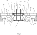
- Fig. 3 schematically shows a part of a first embodiment of a hydraulic trailer system 100 according to the invention.
- a first trailer stroke extender 1 is present.
- the first trailer stroke extender 1 is a trailer stroke extender according to the invention, for example a trailer stroke extender in accordance with one or more of the embodiments as described above and/or below.
- the trailer stroke extender of the embodiment of fig. 3 is a trailer stroke extender according to fig. 1 and fig. 2 .
- the hydraulic trailer system 100 further comprises a first hydraulic trailer 20 and a second hydraulic trailer 30.
- the first hydraulic trailer 20 comprises a loading bed 21 having an upper surface 22, a plurality of individually hydraulically controllable wheels and/or individually hydraulically controllable wheel pairs 23 and a spine beam connector.
- the second hydraulic trailer 30 comprises a loading bed 31 having an upper surface 32, a plurality of individually hydraulically controllable wheels and/or individually hydraulically controllable wheel pairs 33 and a spine beam connector.
- the first and second hydraulic trailer 20, 30 are only partly shown in fig. 3 .
- the loading bed of the first hydraulic trailer 20 and/or the loading bed of the second hydraulic trailer 30 is moveable in vertical direction over a loading bed stroke.
- the first trailer stroke extender 1 makes that a load can be lifted in vertical direction over an additional stroke length as compared to the trailer stroke length.
- the maximum additional stroke length is the stroke length of the first and the second cylinder of the first trailer stroke extender.
- the first trailer stroke extender 1 is arranged between the first hydraulic trailer 20 and the second hydraulic trailer.
- the first cradle-to-beam connector of the first trailer stroke extender 1 is connected to the spine beam connector of the first hydraulic trailer 20 and the second cradle-to-beam connector of the first trailer stroke extender 1 is connected to the spine beam connector of the second hydraulic trailer 30.
- an additional hydraulic trailer is connected to the first hydraulic trailer 20 on the side of the first hydraulic trailer opposite to the side where the spine beam connector of the first hydraulic trailer 20 is connected to the first cradle-to-beam connector of the first trailer stroke extender 1.
- a hydraulic trailer array comprising multiple additional hydraulic trailers is connected to the first hydraulic trailer 20 on the side of the first hydraulic trailer 20 opposite to the side where the spine beam connector of the first hydraulic trailer 20 is connected to the first cradle-to-beam connector of the first trailer stroke extender 1.
- an additional hydraulic trailer is connected to the second hydraulic trailer 30 on the side of the second hydraulic trailer 30 opposite to the side where the spine beam connector of the second hydraulic trailer 30 is connected to the second cradle-to-beam connector of the first trailer stroke extender 1.
- a hydraulic trailer array comprising multiple additional hydraulic trailers is connected to the second hydraulic trailer 30 on the side of the second hydraulic trailer 30 opposite to the side where the spine beam connector of the second hydraulic trailer 30 is connected to the second cradle-to-beam connector of the first trailer stroke extender 1.
- axles of adjacent wheels and/or adjacent wheel pairs of each of the first and second hydraulic trailer 20, 30 are spaced apart from each other in a longitudinal direction of the respective trailer over a wheel axle distance.
- the distance between the first cradle-to-beam connector and the second cradle-to-beam connector of the first trailer stroke extender 1 in a direction parallel to the longitudinal direction of at least one of the first or second hydraulic trailer is 75% - 125% of the wheel axle distance, optionally equal to the wheel axle distance.
- each of the first and the second hydraulic cylinder 10, 11 of the first trailer stroke extender 1 has an extended state and a retracted state, and in the retracted state the load support surface 10.4, 11.4 of each of the first and the second hydraulic cylinder 10, 11 is arranged at the same level as or lower than the upper surface 22, 32 of the loading bed 21, 31 of the first and the second hydraulic trailers 20, 30.
- the cradle frame 2 of the first trailer stroke extender 1 further comprises a first cradle-to-bed connector 16 and a second cradle-to-bed connector 17.
- each one of the first and second hydraulic trailer 20, 30 comprises a first loading bed connector on a first side of the loading bed 21, 31 and a second loading bed connector on a second side of the loading bed 21, 31, wherein the second side is opposite to the first side.
- the first cradle-to-bed connector 16 of the first trailer stroke extender 1 is connected to the second loading bed connector 24 of the first hydraulic trailer 20 and the second cradle-to-bed connector 17 of the first trailer stroke extender 1 is connected to the first loading bed connector 34 of the second hydraulic trailer 30.
- each of the first and second hydraulic trailer 20, 30 comprises a longitudinal spine beam 25, 35 which defines a maximum loading bed bending moment capacity of the loading bed 21, 31 of the respective hydraulic trailer 20, 30, which longitudinal spine beam 25, 35 has a maximum beam bending moment capacity.
- the cradle frame 2 of the first trailer stroke extender 1 has a maximum frame bending moment capacity which is a least 50%, optionally at least 80% and preferably at least 100% of the maximum beam bending moment capacity of the longitudinal spine beam 25, 35 of at least one of the hydraulic trailers 20, 30 to which the first trailer stroke extender 1 is connected.
- the cradle frame 2 of the first trailer stroke extender 1 has a width in lateral direction LA and the loading bed 21, 31 of each of the first and second hydraulic trailer 20, 30 has a width in a direction parallel to the lateral direction LA of the cradle frame 2, and the width of the cradle frame 2 in lateral direction LA is at least 50% of the width of the loading bed 21, 31 of the hydraulic trailers 20, 30 to which the respective cradle frame 2 is attached in a direction parallel to the lateral direction LA of the cradle frame 2, and optionally is at least 80% of the width of the loading bed 21, 31 of the hydraulic trailers 20, 30 to which the respective cradle frame 2 is attached in a direction parallel to the lateral direction LA of the cradle frame.
- the width of the cradle frame 2 in lateral direction is equal to the width of the loading bed 21, 31 of the first and/or second hydraulic trailer 20,30 in a direction parallel to the lateral direction LA of the cradle
- hydraulic trailers and trailer stroke extenders are for example hydraulic trailers and trailer stroke extenders according to the invention, in particular according to any of the embodiments or combination of embodiments as described above and/or below.
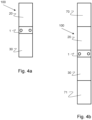
- Fig. 4a shows a first example of an arrangement of hydraulic trailers 20, 30 and a trailer stroke extender 1 in an embodiment of a hydraulic trailer system according to the invention.
- a first trailer stroke extender 1 is arranged between a first hydraulic trailer 20 and a second hydraulic trailer 30.
- This arrangement can be uses as such, or as a building block or module in a larger hydraulic trailer system, in which the arrangement as shown in fig. 4a is combined with one or more further hydraulic trailers and/or one or more further trailer stroke extenders.
- such a larger hydraulic system comprises multiple arrangements of two hydraulic trailers with a trailer stroke extender between them in accordance with fig. 4a .
- Fig. 4b shows a second example of an arrangement of hydraulic trailers 20, 30, 70, 71 and a trailer stroke extender 1 in an embodiment of a hydraulic trailer system according to the invention.
- the arrangement of fig. 4b is similar to the arrangement of fig. 4a . However, in the arrangement of fig. 4b , an additional hydraulic trailer 70 is connected to the first hydraulic trailer 20 on the side of the first hydraulic trailer opposite to the side where the spine beam connector of the first hydraulic trailer 20 is connected to the first cradle-to-beam connector of the first trailer stroke extender 1.
- a further additional hydraulic trailer 71 is connected to the second hydraulic trailer 30 on the side of the second hydraulic trailer 30 opposite to the side where the spine beam connector of the second hydraulic trailer 30 is connected to the second cradle-to-beam connector of the first trailer stroke extender 1.
- Fig. 4c shows a third example of an arrangement of hydraulic trailers 20, 30, 40, 60 and trailer stroke extenders 1, 50 in an embodiment of a hydraulic trailer system according to the invention.
- the arrangement of fig. 4c comprises the arrangement of fig. 4a and a similar arrangement with a third hydraulic trailer 40, a second trailer stroke extender 50 and a fourth hydraulic trailer 60 which is connected to the arrangement as shown in fig. 4a .
- the arrangement of fig. 4c further comprises:
- the second trailer stroke extender 50 is arranged between the third hydraulic trailer 40 and the fourth hydraulic trailer 60.
- the first cradle-to-beam connector of the second trailer stroke extender 50 is connected to the spine beam connector of the third hydraulic trailer 40 and the second cradle-to-beam connector of the second trailer stroke extender 50 is connected to the spine beam connector of the fourth hydraulic trailer 60.
- a first trailer array is present which is formed by the first hydraulic trailer 20, the first trailer stroke extender 1 and the second hydraulic trailer 30.
- a second trailer array is present which is formed by the third hydraulic trailer 40, the second trailer stroke extender 50 and the fourth hydraulic trailer 60.
- the third hydraulic trailer 40 is of the same design as the first hydraulic trailer 20 and/or the fourth hydraulic trailer 60 is of the same design as the second hydraulic trailer 30.
- the design of the second trailer stroke extender 50 is of the same design as the first trailer stroke extender 1.
- the second trailer stroke extender 50 is a trailer stroke extender in accordance with one or more of the embodiments of the trailer stroke extender as described above and/or below.
- the loading bed of the third hydraulic trailer 40 and/or the loading bed of the fourth hydraulic trailer 60 is moveable in vertical direction over a loading bed stroke.
- the second trailer stroke extender makes 50 that a load can be lifted in vertical direction over an additional stroke length as compared to the trailer stroke length.
- the maximum additional stroke length is the stroke length of the first and the second cylinder of the second trailer stroke extender 50.
- the third hydraulic trailer 40 is connected to the second hydraulic trailer 30.
- the second hydraulic trailer 30 and the third hydraulic trailer 40 are directly connected to each other. In this case, there is no further hydraulic trailer arranged between the second hydraulic trailer 30 and the third hydraulic trailer 40.
- the longitudinal axis of the second hydraulic trailer 30 and the longitudinal axis of the third hydraulic trailer 40 extend coaxially with each other.
- the second hydraulic trailer 30 comprises a first spine beam connector and a second spine beam connector, and the first trailer stroke extender 1 is connected to the first spine beam connector.
- the third hydraulic trailer 40 comprises a first spine beam connector and a second spine beam connector, and the second trailer stroke extender 50 is connected to the first spine beam connector.
- the second spine beam connector of the second hydraulic trailer 30 and the second spine beam connector of the third hydraulic trailer 40 are connected to each other.
- Fig. 4d shows a fourth example of an arrangement of hydraulic trailers 20, 30, 40, 60, 70, 71, 72 and trailer stroke extenders 1, 50 in an embodiment of a hydraulic trailer system according to the invention.
- the arrangement of fig. 4d is similar to the arrangement of fig. 4c , however, additional hydraulic trailers 70, 71, 72 have been added to the arrangement as shown in fig. 4c .
- the third hydraulic trailer 40 is indirectly connected to the second hydraulic trailer 30.
- at least one further hydraulic trailer 72 is arranged between the second hydraulic trailer 30 and the third hydraulic trailer 40.
- the longitudinal axis of the second hydraulic trailer 30 and the longitudinal axis of the third hydraulic trailer 40 extend coaxially with each other.
- an additional hydraulic trailer 70 is connected to the first hydraulic trailer 20 on the side of the first hydraulic trailer opposite to the side where the spine beam connector of the first hydraulic trailer 20 is connected to the first cradle-to-beam connector of the first trailer stroke extender 1.
- a further additional hydraulic trailer 71 is connected to the second hydraulic trailer 30 on the side of the second hydraulic trailer 30 opposite to the side where the spine beam connector of the second hydraulic trailer 30 is connected to the second cradle-to-beam connector of the first trailer stroke extender 1.
- Fig. 4e shows a fifth example of an arrangement of hydraulic trailers 20, 30, 40, 60, 20a, 30a, 40a, 60a and trailer stroke extenders 1, 50, 1a, 50a in an embodiment of a hydraulic trailer system according to the invention.
- the arrangement of fig. 4e comprises two trailer arrays which are connected to each other laterally. Each of the two trailer arrays is an arrangement in accordance with fig. 4c .
- One of the trailer arrays is formed by the first hydraulic trailer 20, the first stroke extender 1, the second hydraulic trailer 40, the third hydraulic trailer 40, the second trailer stroke extender 50 and the fourth hydraulic trailer 60.
- the other one of the trailer arrays is formed by hydraulic trailer 20a as the first hydraulic trailer, trailer stroke extender 1a as the first trailer stroke extender, hydraulic trailer 30a as the second hydraulic trailer, hydraulic trailer 40a as the third hydraulic trailer, trailer stroke extender 50a as the second trailer stroke extender and hydraulic trailer 40a as the fourth hydraulic trailer.
- Fig. 4f shows a sixth example of an arrangement of hydraulic trailers 20, 30, 40, and trailer stroke extenders 1, 50 in an embodiment of a hydraulic trailer system according to the invention.
- the spine beam connector of the second hydraulic trailer 30 to which the first trailer stroke extender 1 is connected is a first spine beam connector
- the second hydraulic trailer 30 further comprises a second spine beam connector
- the second trailer stroke extender 50 is arranged between the second hydraulic trailer 30 and the third hydraulic trailer 40, and the first cradle-to-beam connector of the second trailer stroke extender 50 is connected to the second spine beam connector of the second hydraulic trailer 30 and the second cradle-to-beam connector of the second trailer stroke extender 50 is connected to the spine beam connector of the third hydraulic trailer 40.
- a trailer array which comprises, in this order, the first hydraulic trailer 20, the first trailer stroke extender 1, the second hydraulic trailer 40, the second trailer stroke extender 50, and the third hydraulic trailer 40.
- Fig. 5 shows schematically an example of a monopile support 80 which can be used in a hydraulic trailer system according to the invention.
- the monopile support 80 is supported by the load support surfaces of the first and second hydraulic cylinders of a first trailer stroke extender 1, the load support surfaces of the first and second hydraulic cylinders of a second trailer stroke extender 1a and the load support surfaces of the first and second hydraulic cylinders of a third trailer stroke extender 1b.
- the first, second and third trailer stroke extenders 1, 1a, 1b are arranged adjacent to each other in lateral direction.
- the first trailer stroke extender 1 is connected to the second trailer stroke extender 1a and the third trailer stroke extender 1b is connected to the second trailer stroke extender 1a.
- the first trailer stroke extender 1 comprises a first lateral cradle connector
- the second trailer stroke extender 1a comprises a first lateral cradle connector and a second lateral cradle connector
- the third trailer stroke extender 1b comprises a first lateral cradle connector
- the first lateral cradle connector of the first trailer stroke extender 1 is connected to the first lateral cradle connector of the second trailer stroke extender 1a
- the first lateral cradle connector of the third trailer stroke extender 1b is connected to the second lateral cradle connector of the second trailer stroke extender 1a.
- Monopiles e.g. as used for wind turbines, are an example of a load that is regularly transported using hydraulic trailers. Arranging a monopile support on the load support surfaces of the first and second hydraulic cylinders of the first trailer stroke extender allows to move the monopile in vertical direction relative to the loading beds of the first and second hydraulic trailer.
Landscapes
- Engineering & Computer Science (AREA)
- Mechanical Engineering (AREA)
- Transportation (AREA)
- Chemical & Material Sciences (AREA)
- Combustion & Propulsion (AREA)
- Structural Engineering (AREA)
- Geology (AREA)
- Life Sciences & Earth Sciences (AREA)
- Health & Medical Sciences (AREA)
- Public Health (AREA)
- Vehicle Cleaning, Maintenance, Repair, Refitting, And Outriggers (AREA)
- Fluid-Pressure Circuits (AREA)
- Body Structure For Vehicles (AREA)
Applications Claiming Priority (2)
| Application Number | Priority Date | Filing Date | Title |
|---|---|---|---|
| NL2032977A NL2032977B1 (en) | 2022-09-07 | 2022-09-07 | Trailer stroke extender and hydraulic trailer system |
| EP23194410.9A EP4335695B1 (de) | 2022-09-07 | 2023-08-31 | Anhängerhubverlängerung und hydraulisches anhängersystem |
Related Parent Applications (1)
| Application Number | Title | Priority Date | Filing Date |
|---|---|---|---|
| EP23194410.9A Division EP4335695B1 (de) | 2022-09-07 | 2023-08-31 | Anhängerhubverlängerung und hydraulisches anhängersystem |
Publications (2)
| Publication Number | Publication Date |
|---|---|
| EP4524006A2 true EP4524006A2 (de) | 2025-03-19 |
| EP4524006A3 EP4524006A3 (de) | 2025-06-04 |
Family
ID=84053409
Family Applications (2)
| Application Number | Title | Priority Date | Filing Date |
|---|---|---|---|
| EP24223140.5A Withdrawn EP4524006A3 (de) | 2022-09-07 | 2023-08-31 | Anhängerhubverlängerung und hydraulisches anhängersystem |
| EP23194410.9A Active EP4335695B1 (de) | 2022-09-07 | 2023-08-31 | Anhängerhubverlängerung und hydraulisches anhängersystem |
Family Applications After (1)
| Application Number | Title | Priority Date | Filing Date |
|---|---|---|---|
| EP23194410.9A Active EP4335695B1 (de) | 2022-09-07 | 2023-08-31 | Anhängerhubverlängerung und hydraulisches anhängersystem |
Country Status (8)
| Country | Link |
|---|---|
| US (1) | US12503164B2 (de) |
| EP (2) | EP4524006A3 (de) |
| JP (1) | JP2024037708A (de) |
| CN (1) | CN117656719A (de) |
| CA (1) | CA3211026A1 (de) |
| ES (1) | ES3014086T3 (de) |
| NL (1) | NL2032977B1 (de) |
| PL (1) | PL4335695T3 (de) |
Families Citing this family (1)
| Publication number | Priority date | Publication date | Assignee | Title |
|---|---|---|---|---|
| NL2032977B1 (en) * | 2022-09-07 | 2024-03-21 | Mammoet Holding B V | Trailer stroke extender and hydraulic trailer system |
Family Cites Families (18)
| Publication number | Priority date | Publication date | Assignee | Title |
|---|---|---|---|---|
| US5375866A (en) * | 1993-03-01 | 1994-12-27 | Wagner; Wilbert A. | Extension axle apparatus for over-the-road trailer assembly |
| US20060119080A1 (en) * | 1998-11-06 | 2006-06-08 | Tony Damron | Extendable trailer |
| CA2564544C (en) * | 2006-10-19 | 2011-09-20 | Bidell Equipment Limited Partnership | Mobile wear and tear resistant gas compressor |
| MX350140B (es) * | 2008-06-13 | 2017-08-28 | Concaten Inc | Barrera móvil. |
| US9296327B2 (en) * | 2011-02-09 | 2016-03-29 | Trinity Industries, Inc. | Trailer apparatus for transporting utility poles and methods for same |
| KR101313053B1 (ko) | 2012-03-22 | 2013-09-30 | 안종오 | 스마트단말의 홈 스크린 바탕화면에 대한 원격 직접제어를 이용한 유통매장 쇼핑서비스 제공 방법, 그리고 이를 이용한 홈 스크린 바탕화면 쇼핑 프로그램을 기록한 컴퓨터로 판독가능한 기록매체 |
| DE102012018575B4 (de) | 2012-09-20 | 2015-05-28 | Scheuerle Fahrzeugfabrik Gmbh | Schwerlast-Transportfahrzeug mit einem Fahrgestell und einem nur durch Hydraulikzylinder mit dem Fahrgestell verbundenen Lastauflagebett |
| US8695998B1 (en) * | 2013-02-20 | 2014-04-15 | Saf-Holland, Inc. | Axle lift assembly |
| NL2013187B1 (en) * | 2014-07-15 | 2016-09-13 | Mammoet Eng B V | Method and assembly for transport of heavy loads. |
| US9527539B1 (en) * | 2015-08-13 | 2016-12-27 | Duo Lift Manufacturing Co., Inc. | Swather header transport trailer |
| US10875590B2 (en) * | 2017-05-26 | 2020-12-29 | David W. Lutz | Modular beam hauler |
| US11370482B2 (en) * | 2018-08-30 | 2022-06-28 | Master Solutions, Inc. | Hydraulic steering system |
| LU100932B1 (en) * | 2018-09-21 | 2020-03-23 | Faymonville Distrib Ag | Semi-trailer for transporting a load to be moved |
| US10759321B1 (en) * | 2019-03-16 | 2020-09-01 | William Wayne Cook, Jr. | Extendable trailer |
| NL2025942B1 (en) * | 2020-06-29 | 2022-03-04 | Mammoet Holding B V | Trailer system, method for transporting an object by a trailer system and trailer jack system |
| DE102021001083B4 (de) * | 2021-03-01 | 2022-09-08 | Scheuerle Fahrzeugfabrik Gmbh | Hydraulisch gelenktes Transportfahrzeug, vorzugsweise mit variabler Breite und Spurweite |
| NL2032977B1 (en) * | 2022-09-07 | 2024-03-21 | Mammoet Holding B V | Trailer stroke extender and hydraulic trailer system |
| CN220662629U (zh) * | 2023-09-05 | 2024-03-26 | 广东富华重工制造有限公司 | 一种装配式挂车滑架 |
-
2022
- 2022-09-07 NL NL2032977A patent/NL2032977B1/en active
-
2023
- 2023-08-07 US US18/230,948 patent/US12503164B2/en active Active
- 2023-08-31 EP EP24223140.5A patent/EP4524006A3/de not_active Withdrawn
- 2023-08-31 PL PL23194410.9T patent/PL4335695T3/pl unknown
- 2023-08-31 EP EP23194410.9A patent/EP4335695B1/de active Active
- 2023-08-31 ES ES23194410T patent/ES3014086T3/es active Active
- 2023-09-05 CA CA3211026A patent/CA3211026A1/en active Pending
- 2023-09-06 JP JP2023144425A patent/JP2024037708A/ja active Pending
- 2023-09-07 CN CN202311150375.1A patent/CN117656719A/zh active Pending
Also Published As
| Publication number | Publication date |
|---|---|
| JP2024037708A (ja) | 2024-03-19 |
| CA3211026A1 (en) | 2024-03-07 |
| EP4335695A1 (de) | 2024-03-13 |
| NL2032977B1 (en) | 2024-03-21 |
| EP4524006A3 (de) | 2025-06-04 |
| US20240075985A1 (en) | 2024-03-07 |
| ES3014086T3 (en) | 2025-04-16 |
| US12503164B2 (en) | 2025-12-23 |
| CN117656719A (zh) | 2024-03-08 |
| PL4335695T3 (pl) | 2025-05-12 |
| EP4335695B1 (de) | 2024-12-25 |
| EP4335695C0 (de) | 2024-12-25 |
Similar Documents
| Publication | Publication Date | Title |
|---|---|---|
| US5394959A (en) | Scissor lift apparatus for work platforms and the like | |
| US3861716A (en) | Platform lift transporter | |
| CN103552618B (zh) | 一种枢转轴系统 | |
| US4060145A (en) | Lift bed trailer suspension subframe | |
| US6516961B1 (en) | Ringlift crane | |
| FI124889B (fi) | Sovitelma metsäkoneessa ja vastaavalla sovitelmalla varustettu metsäkone | |
| EP4335695A1 (de) | Anhängerhubverlängerung und hydraulisches anhängersystem | |
| EP1024109A2 (de) | Anbaugerät für Flurförderzeuge mit einem Hubmast, insbesondere für Gabelstapler | |
| DE2913685A1 (de) | Lastentragende fahrzeuge | |
| WO2026090525A1 (en) | Apparatuses and methods for a trailer and elevating trailer bed | |
| EP3507233B1 (de) | Flurförderzeug und antriebsradlagervorrichtung für flurförderzeuge. | |
| DE102009036306A1 (de) | Lastumschlag-Fahrzeug | |
| EP3184405A1 (de) | Satteltiefladeanhänger | |
| EP2466157B1 (de) | Teleskopischer hydraulikzylinder | |
| US3490633A (en) | Assembly for laterally shifting and pivoting a mast of a lift truck | |
| FI61435C (fi) | Foerfarande och anordning foer hantering och transportering i ynnerhet mellan ett ro/ro-fartyg och en terminal av ett e nhtslass bestaoende av en eller flera containrar eller dyli ka | |
| KR102675733B1 (ko) | 이동될 화물을 운송하기 위한 세미 트레일러 | |
| CN212269323U (zh) | 顶升主机总成及模组化自行式液压顶升装置 | |
| CN108945122A (zh) | 多功能重载运输车 | |
| EP0977676B1 (de) | Transportanhänger zum aufheben und bewegen | |
| RU2023122803A (ru) | Удлинитель хода прицепа и гидравлическая прицепная система | |
| CN109551989B (zh) | 一种重型电驱动舵轮 | |
| EP1733995B1 (de) | Verladefahrzeug | |
| DE19909466A1 (de) | Schienengebundenes Transport- oder Fördergerät | |
| US20030108413A1 (en) | Load lifting attachment for skid-steer loader |
Legal Events
| Date | Code | Title | Description |
|---|---|---|---|
| PUAI | Public reference made under article 153(3) epc to a published international application that has entered the european phase |
Free format text: ORIGINAL CODE: 0009012 |
|
| STAA | Information on the status of an ep patent application or granted ep patent |
Free format text: STATUS: THE APPLICATION HAS BEEN PUBLISHED |
|
| AC | Divisional application: reference to earlier application |
Ref document number: 4335695 Country of ref document: EP Kind code of ref document: P |
|
| AK | Designated contracting states |
Kind code of ref document: A2 Designated state(s): AL AT BE BG CH CY CZ DE DK EE ES FI FR GB GR HR HU IE IS IT LI LT LU LV MC ME MK MT NL NO PL PT RO RS SE SI SK SM TR |
|
| REG | Reference to a national code |
Ref country code: DE Ref legal event code: R079 Free format text: PREVIOUS MAIN CLASS: B62D0063000000 Ipc: B60P0003400000 |
|
| PUAL | Search report despatched |
Free format text: ORIGINAL CODE: 0009013 |
|
| AK | Designated contracting states |
Kind code of ref document: A3 Designated state(s): AL AT BE BG CH CY CZ DE DK EE ES FI FR GB GR HR HU IE IS IT LI LT LU LV MC ME MK MT NL NO PL PT RO RS SE SI SK SM TR |
|
| RIC1 | Information provided on ipc code assigned before grant |
Ipc: B62D 63/00 20060101ALI20250429BHEP Ipc: B66F 1/00 20060101ALI20250429BHEP Ipc: B60P 1/02 20060101ALI20250429BHEP Ipc: B60P 3/40 20060101AFI20250429BHEP |
|
| STAA | Information on the status of an ep patent application or granted ep patent |
Free format text: STATUS: THE APPLICATION IS DEEMED TO BE WITHDRAWN |
|
| 18D | Application deemed to be withdrawn |
Effective date: 20251205 |