EP4523894A1 - Joining method - Google Patents
Joining method Download PDFInfo
- Publication number
- EP4523894A1 EP4523894A1 EP24194519.5A EP24194519A EP4523894A1 EP 4523894 A1 EP4523894 A1 EP 4523894A1 EP 24194519 A EP24194519 A EP 24194519A EP 4523894 A1 EP4523894 A1 EP 4523894A1
- Authority
- EP
- European Patent Office
- Prior art keywords
- joining
- resin
- dam
- joining body
- heater
- Prior art date
- Legal status (The legal status is an assumption and is not a legal conclusion. Google has not performed a legal analysis and makes no representation as to the accuracy of the status listed.)
- Granted
Links
Images




Classifications
-
- B—PERFORMING OPERATIONS; TRANSPORTING
- B29—WORKING OF PLASTICS; WORKING OF SUBSTANCES IN A PLASTIC STATE IN GENERAL
- B29C—SHAPING OR JOINING OF PLASTICS; SHAPING OF MATERIAL IN A PLASTIC STATE, NOT OTHERWISE PROVIDED FOR; AFTER-TREATMENT OF THE SHAPED PRODUCTS, e.g. REPAIRING
- B29C65/00—Joining or sealing of preformed parts, e.g. welding of plastics materials; Apparatus therefor
- B29C65/02—Joining or sealing of preformed parts, e.g. welding of plastics materials; Apparatus therefor by heating, with or without pressure
- B29C65/18—Joining or sealing of preformed parts, e.g. welding of plastics materials; Apparatus therefor by heating, with or without pressure using heated tools
-
- B—PERFORMING OPERATIONS; TRANSPORTING
- B29—WORKING OF PLASTICS; WORKING OF SUBSTANCES IN A PLASTIC STATE IN GENERAL
- B29C—SHAPING OR JOINING OF PLASTICS; SHAPING OF MATERIAL IN A PLASTIC STATE, NOT OTHERWISE PROVIDED FOR; AFTER-TREATMENT OF THE SHAPED PRODUCTS, e.g. REPAIRING
- B29C65/00—Joining or sealing of preformed parts, e.g. welding of plastics materials; Apparatus therefor
- B29C65/02—Joining or sealing of preformed parts, e.g. welding of plastics materials; Apparatus therefor by heating, with or without pressure
-
- B—PERFORMING OPERATIONS; TRANSPORTING
- B29—WORKING OF PLASTICS; WORKING OF SUBSTANCES IN A PLASTIC STATE IN GENERAL
- B29C—SHAPING OR JOINING OF PLASTICS; SHAPING OF MATERIAL IN A PLASTIC STATE, NOT OTHERWISE PROVIDED FOR; AFTER-TREATMENT OF THE SHAPED PRODUCTS, e.g. REPAIRING
- B29C65/00—Joining or sealing of preformed parts, e.g. welding of plastics materials; Apparatus therefor
- B29C65/02—Joining or sealing of preformed parts, e.g. welding of plastics materials; Apparatus therefor by heating, with or without pressure
- B29C65/18—Joining or sealing of preformed parts, e.g. welding of plastics materials; Apparatus therefor by heating, with or without pressure using heated tools
- B29C65/24—Joining or sealing of preformed parts, e.g. welding of plastics materials; Apparatus therefor by heating, with or without pressure using heated tools characterised by the means for heating the tool
- B29C65/30—Electrical means
-
- B—PERFORMING OPERATIONS; TRANSPORTING
- B29—WORKING OF PLASTICS; WORKING OF SUBSTANCES IN A PLASTIC STATE IN GENERAL
- B29C—SHAPING OR JOINING OF PLASTICS; SHAPING OF MATERIAL IN A PLASTIC STATE, NOT OTHERWISE PROVIDED FOR; AFTER-TREATMENT OF THE SHAPED PRODUCTS, e.g. REPAIRING
- B29C66/00—General aspects of processes or apparatus for joining preformed parts
- B29C66/01—General aspects dealing with the joint area or with the area to be joined
- B29C66/05—Particular design of joint configurations
-
- B—PERFORMING OPERATIONS; TRANSPORTING
- B29—WORKING OF PLASTICS; WORKING OF SUBSTANCES IN A PLASTIC STATE IN GENERAL
- B29C—SHAPING OR JOINING OF PLASTICS; SHAPING OF MATERIAL IN A PLASTIC STATE, NOT OTHERWISE PROVIDED FOR; AFTER-TREATMENT OF THE SHAPED PRODUCTS, e.g. REPAIRING
- B29C66/00—General aspects of processes or apparatus for joining preformed parts
- B29C66/01—General aspects dealing with the joint area or with the area to be joined
- B29C66/05—Particular design of joint configurations
- B29C66/10—Particular design of joint configurations particular design of the joint cross-sections
- B29C66/11—Joint cross-sections comprising a single joint-segment, i.e. one of the parts to be joined comprising a single joint-segment in the joint cross-section
- B29C66/112—Single lapped joints
- B29C66/1122—Single lap to lap joints, i.e. overlap joints
-
- B—PERFORMING OPERATIONS; TRANSPORTING
- B29—WORKING OF PLASTICS; WORKING OF SUBSTANCES IN A PLASTIC STATE IN GENERAL
- B29C—SHAPING OR JOINING OF PLASTICS; SHAPING OF MATERIAL IN A PLASTIC STATE, NOT OTHERWISE PROVIDED FOR; AFTER-TREATMENT OF THE SHAPED PRODUCTS, e.g. REPAIRING
- B29C66/00—General aspects of processes or apparatus for joining preformed parts
- B29C66/01—General aspects dealing with the joint area or with the area to be joined
- B29C66/32—Measures for keeping the burr form under control; Avoiding burr formation; Shaping the burr
- B29C66/326—Shaping the burr, e.g. by the joining tool
-
- B—PERFORMING OPERATIONS; TRANSPORTING
- B29—WORKING OF PLASTICS; WORKING OF SUBSTANCES IN A PLASTIC STATE IN GENERAL
- B29C—SHAPING OR JOINING OF PLASTICS; SHAPING OF MATERIAL IN A PLASTIC STATE, NOT OTHERWISE PROVIDED FOR; AFTER-TREATMENT OF THE SHAPED PRODUCTS, e.g. REPAIRING
- B29C66/00—General aspects of processes or apparatus for joining preformed parts
- B29C66/40—General aspects of joining substantially flat articles, e.g. plates, sheets or web-like materials; Making flat seams in tubular or hollow articles; Joining single elements to substantially flat surfaces
- B29C66/41—Joining substantially flat articles ; Making flat seams in tubular or hollow articles
- B29C66/45—Joining of substantially the whole surface of the articles
-
- B—PERFORMING OPERATIONS; TRANSPORTING
- B29—WORKING OF PLASTICS; WORKING OF SUBSTANCES IN A PLASTIC STATE IN GENERAL
- B29C—SHAPING OR JOINING OF PLASTICS; SHAPING OF MATERIAL IN A PLASTIC STATE, NOT OTHERWISE PROVIDED FOR; AFTER-TREATMENT OF THE SHAPED PRODUCTS, e.g. REPAIRING
- B29C66/00—General aspects of processes or apparatus for joining preformed parts
- B29C66/40—General aspects of joining substantially flat articles, e.g. plates, sheets or web-like materials; Making flat seams in tubular or hollow articles; Joining single elements to substantially flat surfaces
- B29C66/47—Joining single elements to sheets, plates or other substantially flat surfaces
- B29C66/472—Joining single elements to sheets, plates or other substantially flat surfaces said single elements being substantially flat
-
- B—PERFORMING OPERATIONS; TRANSPORTING
- B29—WORKING OF PLASTICS; WORKING OF SUBSTANCES IN A PLASTIC STATE IN GENERAL
- B29C—SHAPING OR JOINING OF PLASTICS; SHAPING OF MATERIAL IN A PLASTIC STATE, NOT OTHERWISE PROVIDED FOR; AFTER-TREATMENT OF THE SHAPED PRODUCTS, e.g. REPAIRING
- B29C66/00—General aspects of processes or apparatus for joining preformed parts
- B29C66/70—General aspects of processes or apparatus for joining preformed parts characterised by the composition, physical properties or the structure of the material of the parts to be joined; Joining with non-plastics material
- B29C66/72—General aspects of processes or apparatus for joining preformed parts characterised by the composition, physical properties or the structure of the material of the parts to be joined; Joining with non-plastics material characterised by the structure of the material of the parts to be joined
- B29C66/721—Fibre-reinforced materials
- B29C66/7212—Fibre-reinforced materials characterised by the composition of the fibres
-
- B—PERFORMING OPERATIONS; TRANSPORTING
- B29—WORKING OF PLASTICS; WORKING OF SUBSTANCES IN A PLASTIC STATE IN GENERAL
- B29C—SHAPING OR JOINING OF PLASTICS; SHAPING OF MATERIAL IN A PLASTIC STATE, NOT OTHERWISE PROVIDED FOR; AFTER-TREATMENT OF THE SHAPED PRODUCTS, e.g. REPAIRING
- B29C66/00—General aspects of processes or apparatus for joining preformed parts
- B29C66/70—General aspects of processes or apparatus for joining preformed parts characterised by the composition, physical properties or the structure of the material of the parts to be joined; Joining with non-plastics material
- B29C66/73—General aspects of processes or apparatus for joining preformed parts characterised by the composition, physical properties or the structure of the material of the parts to be joined; Joining with non-plastics material characterised by the intensive physical properties of the material of the parts to be joined, by the optical properties of the material of the parts to be joined, by the extensive physical properties of the parts to be joined, by the state of the material of the parts to be joined or by the material of the parts to be joined being a thermoplastic or a thermoset
- B29C66/739—General aspects of processes or apparatus for joining preformed parts characterised by the composition, physical properties or the structure of the material of the parts to be joined; Joining with non-plastics material characterised by the intensive physical properties of the material of the parts to be joined, by the optical properties of the material of the parts to be joined, by the extensive physical properties of the parts to be joined, by the state of the material of the parts to be joined or by the material of the parts to be joined being a thermoplastic or a thermoset characterised by the material of the parts to be joined being a thermoplastic or a thermoset
- B29C66/7392—General aspects of processes or apparatus for joining preformed parts characterised by the composition, physical properties or the structure of the material of the parts to be joined; Joining with non-plastics material characterised by the intensive physical properties of the material of the parts to be joined, by the optical properties of the material of the parts to be joined, by the extensive physical properties of the parts to be joined, by the state of the material of the parts to be joined or by the material of the parts to be joined being a thermoplastic or a thermoset characterised by the material of the parts to be joined being a thermoplastic or a thermoset characterised by the material of at least one of the parts being a thermoplastic
- B29C66/73921—General aspects of processes or apparatus for joining preformed parts characterised by the composition, physical properties or the structure of the material of the parts to be joined; Joining with non-plastics material characterised by the intensive physical properties of the material of the parts to be joined, by the optical properties of the material of the parts to be joined, by the extensive physical properties of the parts to be joined, by the state of the material of the parts to be joined or by the material of the parts to be joined being a thermoplastic or a thermoset characterised by the material of the parts to be joined being a thermoplastic or a thermoset characterised by the material of at least one of the parts being a thermoplastic characterised by the materials of both parts being thermoplastics
-
- B—PERFORMING OPERATIONS; TRANSPORTING
- B29—WORKING OF PLASTICS; WORKING OF SUBSTANCES IN A PLASTIC STATE IN GENERAL
- B29C—SHAPING OR JOINING OF PLASTICS; SHAPING OF MATERIAL IN A PLASTIC STATE, NOT OTHERWISE PROVIDED FOR; AFTER-TREATMENT OF THE SHAPED PRODUCTS, e.g. REPAIRING
- B29C66/00—General aspects of processes or apparatus for joining preformed parts
- B29C66/80—General aspects of machine operations or constructions and parts thereof
- B29C66/81—General aspects of the pressing elements, i.e. the elements applying pressure on the parts to be joined in the area to be joined, e.g. the welding jaws or clamps
- B29C66/812—General aspects of the pressing elements, i.e. the elements applying pressure on the parts to be joined in the area to be joined, e.g. the welding jaws or clamps characterised by the composition, by the structure, by the intensive physical properties or by the optical properties of the material constituting the pressing elements, e.g. constituting the welding jaws or clamps
- B29C66/8122—General aspects of the pressing elements, i.e. the elements applying pressure on the parts to be joined in the area to be joined, e.g. the welding jaws or clamps characterised by the composition, by the structure, by the intensive physical properties or by the optical properties of the material constituting the pressing elements, e.g. constituting the welding jaws or clamps characterised by the composition of the material constituting the pressing elements, e.g. constituting the welding jaws or clamps
-
- B—PERFORMING OPERATIONS; TRANSPORTING
- B29—WORKING OF PLASTICS; WORKING OF SUBSTANCES IN A PLASTIC STATE IN GENERAL
- B29C—SHAPING OR JOINING OF PLASTICS; SHAPING OF MATERIAL IN A PLASTIC STATE, NOT OTHERWISE PROVIDED FOR; AFTER-TREATMENT OF THE SHAPED PRODUCTS, e.g. REPAIRING
- B29C66/00—General aspects of processes or apparatus for joining preformed parts
- B29C66/80—General aspects of machine operations or constructions and parts thereof
- B29C66/81—General aspects of the pressing elements, i.e. the elements applying pressure on the parts to be joined in the area to be joined, e.g. the welding jaws or clamps
- B29C66/814—General aspects of the pressing elements, i.e. the elements applying pressure on the parts to be joined in the area to be joined, e.g. the welding jaws or clamps characterised by the design of the pressing elements, e.g. of the welding jaws or clamps
- B29C66/8145—General aspects of the pressing elements, i.e. the elements applying pressure on the parts to be joined in the area to be joined, e.g. the welding jaws or clamps characterised by the design of the pressing elements, e.g. of the welding jaws or clamps characterised by the constructional aspects of the pressing elements, e.g. of the welding jaws or clamps
- B29C66/81461—General aspects of the pressing elements, i.e. the elements applying pressure on the parts to be joined in the area to be joined, e.g. the welding jaws or clamps characterised by the design of the pressing elements, e.g. of the welding jaws or clamps characterised by the constructional aspects of the pressing elements, e.g. of the welding jaws or clamps being multi-lamellar or segmented, i.e. comprising a plurality of strips, plates or stacked elements
-
- B—PERFORMING OPERATIONS; TRANSPORTING
- B29—WORKING OF PLASTICS; WORKING OF SUBSTANCES IN A PLASTIC STATE IN GENERAL
- B29C—SHAPING OR JOINING OF PLASTICS; SHAPING OF MATERIAL IN A PLASTIC STATE, NOT OTHERWISE PROVIDED FOR; AFTER-TREATMENT OF THE SHAPED PRODUCTS, e.g. REPAIRING
- B29C66/00—General aspects of processes or apparatus for joining preformed parts
- B29C66/80—General aspects of machine operations or constructions and parts thereof
- B29C66/81—General aspects of the pressing elements, i.e. the elements applying pressure on the parts to be joined in the area to be joined, e.g. the welding jaws or clamps
- B29C66/818—General aspects of the pressing elements, i.e. the elements applying pressure on the parts to be joined in the area to be joined, e.g. the welding jaws or clamps characterised by the cooling constructional aspects, or by the thermal or electrical insulating or conducting constructional aspects of the welding jaws or of the clamps ; comprising means for compensating for the thermal expansion of the welding jaws or of the clamps
- B29C66/8182—General aspects of the pressing elements, i.e. the elements applying pressure on the parts to be joined in the area to be joined, e.g. the welding jaws or clamps characterised by the cooling constructional aspects, or by the thermal or electrical insulating or conducting constructional aspects of the welding jaws or of the clamps ; comprising means for compensating for the thermal expansion of the welding jaws or of the clamps characterised by the thermal insulating constructional aspects
- B29C66/81821—General aspects of the pressing elements, i.e. the elements applying pressure on the parts to be joined in the area to be joined, e.g. the welding jaws or clamps characterised by the cooling constructional aspects, or by the thermal or electrical insulating or conducting constructional aspects of the welding jaws or of the clamps ; comprising means for compensating for the thermal expansion of the welding jaws or of the clamps characterised by the thermal insulating constructional aspects of the welding jaws
-
- B—PERFORMING OPERATIONS; TRANSPORTING
- B29—WORKING OF PLASTICS; WORKING OF SUBSTANCES IN A PLASTIC STATE IN GENERAL
- B29C—SHAPING OR JOINING OF PLASTICS; SHAPING OF MATERIAL IN A PLASTIC STATE, NOT OTHERWISE PROVIDED FOR; AFTER-TREATMENT OF THE SHAPED PRODUCTS, e.g. REPAIRING
- B29C66/00—General aspects of processes or apparatus for joining preformed parts
- B29C66/80—General aspects of machine operations or constructions and parts thereof
- B29C66/81—General aspects of the pressing elements, i.e. the elements applying pressure on the parts to be joined in the area to be joined, e.g. the welding jaws or clamps
- B29C66/818—General aspects of the pressing elements, i.e. the elements applying pressure on the parts to be joined in the area to be joined, e.g. the welding jaws or clamps characterised by the cooling constructional aspects, or by the thermal or electrical insulating or conducting constructional aspects of the welding jaws or of the clamps ; comprising means for compensating for the thermal expansion of the welding jaws or of the clamps
- B29C66/8183—General aspects of the pressing elements, i.e. the elements applying pressure on the parts to be joined in the area to be joined, e.g. the welding jaws or clamps characterised by the cooling constructional aspects, or by the thermal or electrical insulating or conducting constructional aspects of the welding jaws or of the clamps ; comprising means for compensating for the thermal expansion of the welding jaws or of the clamps characterised by the thermal conducting constructional aspects
- B29C66/81831—General aspects of the pressing elements, i.e. the elements applying pressure on the parts to be joined in the area to be joined, e.g. the welding jaws or clamps characterised by the cooling constructional aspects, or by the thermal or electrical insulating or conducting constructional aspects of the welding jaws or of the clamps ; comprising means for compensating for the thermal expansion of the welding jaws or of the clamps characterised by the thermal conducting constructional aspects of the welding jaws
-
- B—PERFORMING OPERATIONS; TRANSPORTING
- B29—WORKING OF PLASTICS; WORKING OF SUBSTANCES IN A PLASTIC STATE IN GENERAL
- B29C—SHAPING OR JOINING OF PLASTICS; SHAPING OF MATERIAL IN A PLASTIC STATE, NOT OTHERWISE PROVIDED FOR; AFTER-TREATMENT OF THE SHAPED PRODUCTS, e.g. REPAIRING
- B29C66/00—General aspects of processes or apparatus for joining preformed parts
- B29C66/80—General aspects of machine operations or constructions and parts thereof
- B29C66/83—General aspects of machine operations or constructions and parts thereof characterised by the movement of the joining or pressing tools
- B29C66/832—Reciprocating joining or pressing tools
- B29C66/8322—Joining or pressing tools reciprocating along one axis
-
- B—PERFORMING OPERATIONS; TRANSPORTING
- B29—WORKING OF PLASTICS; WORKING OF SUBSTANCES IN A PLASTIC STATE IN GENERAL
- B29C—SHAPING OR JOINING OF PLASTICS; SHAPING OF MATERIAL IN A PLASTIC STATE, NOT OTHERWISE PROVIDED FOR; AFTER-TREATMENT OF THE SHAPED PRODUCTS, e.g. REPAIRING
- B29C66/00—General aspects of processes or apparatus for joining preformed parts
- B29C66/80—General aspects of machine operations or constructions and parts thereof
- B29C66/83—General aspects of machine operations or constructions and parts thereof characterised by the movement of the joining or pressing tools
- B29C66/832—Reciprocating joining or pressing tools
- B29C66/8322—Joining or pressing tools reciprocating along one axis
- B29C66/83221—Joining or pressing tools reciprocating along one axis cooperating reciprocating tools, each tool reciprocating along one axis
-
- B—PERFORMING OPERATIONS; TRANSPORTING
- B29—WORKING OF PLASTICS; WORKING OF SUBSTANCES IN A PLASTIC STATE IN GENERAL
- B29K—INDEXING SCHEME ASSOCIATED WITH SUBCLASSES B29B, B29C OR B29D, RELATING TO MOULDING MATERIALS OR TO MATERIALS FOR MOULDS, REINFORCEMENTS, FILLERS OR PREFORMED PARTS, e.g. INSERTS
- B29K2105/00—Condition, form or state of moulded material or of the material to be shaped
- B29K2105/06—Condition, form or state of moulded material or of the material to be shaped containing reinforcements, fillers or inserts
- B29K2105/12—Condition, form or state of moulded material or of the material to be shaped containing reinforcements, fillers or inserts of short lengths, e.g. chopped filaments, staple fibres or bristles
-
- B—PERFORMING OPERATIONS; TRANSPORTING
- B29—WORKING OF PLASTICS; WORKING OF SUBSTANCES IN A PLASTIC STATE IN GENERAL
- B29K—INDEXING SCHEME ASSOCIATED WITH SUBCLASSES B29B, B29C OR B29D, RELATING TO MOULDING MATERIALS OR TO MATERIALS FOR MOULDS, REINFORCEMENTS, FILLERS OR PREFORMED PARTS, e.g. INSERTS
- B29K2307/00—Use of elements other than metals as reinforcement
- B29K2307/04—Carbon
-
- B—PERFORMING OPERATIONS; TRANSPORTING
- B29—WORKING OF PLASTICS; WORKING OF SUBSTANCES IN A PLASTIC STATE IN GENERAL
- B29L—INDEXING SCHEME ASSOCIATED WITH SUBCLASS B29C, RELATING TO PARTICULAR ARTICLES
- B29L2031/00—Other particular articles
- B29L2031/30—Vehicles, e.g. ships or aircraft, or body parts thereof
- B29L2031/3076—Aircrafts
Definitions
- the present disclosure relates to a method of joining thermoplastic composite members by heat fusion.
- heat transfer fusion is known as a heat fusion technique for a thermoplastic composite member used as a structural material of an aircraft.
- a heater is brought into contact with an outer surface of the thermoplastic composite member, heat generated by the heater is transferred to the inside of the material, and pressure is applied while melting a fusion interface until the melting point is exceeded.
- a thermoplastic composite member used as a structural material of an aircraft is made of carbon fiber reinforced thermoplastics (CFRTP).
- fibers and a resin may be extruded outward from a circumferential edge of a member to be fused as illustrated in FIG. 7 , for example.
- the plate thickness of the joined member with such extrusion is reduced more than desired, or the strength thereof is reduced because the fiber volume content (Vf) is reduced more than desired.
- the extruded portion interferes with other members and fails to assemble them in a subsequent process, or the extruded portion falls off and causes contamination.
- Patent Document 1 discloses a molding die for a thermoplastic composite material.
- the molding die at least a part of a cavity formed by an upper die and a lower die is opened, and cooling fins are provided at end portions of the opened cavity so as to be continuous with a molding surface of each of the upper die and the lower die.
- Patent Document 2 proposes that, when thermoplastic plastics on which aluminum foil is laminated are caused to come into contact with each other and welded, first stage pressurizing compression is performed at a low pressure, and then second stage pressurizing compression is performed at a pressure higher than the pressure in the first stage pressurizing compression.
- Patent Document 1 relates to a technique for molding a single thermoplastic composite member and does not suggest heat fusion of two layered thermoplastic composite members.
- Patent Document 2 discloses heat fusion of two thermoplastic composite members. However, in Patent Document 2, thermoplastic plastic at a joined portion is pushed out to the inner side direction of a flange, a resin pool of the thermoplastic plastic is formed on the inner side, and the thermoplastic plastic is sealed, thereby obtaining a seal layer having a strong adhesive force. Therefore, Patent Document 2 does not suggest the above-described extrusion.
- an object of the present disclosure is to control a shape of extrusion that occurs during heat fusion of two thermoplastic composite members.
- a joining method includes: a first step of layering a first joining body and a second joining body having a smaller plane area than the first joining body; and a second step of performing heating and pressurization with a heater from a side of the second joining body. In the second step, a resin dam is interposed between the second joining body and the heater.
- the resin dam includes: a base body having one of front and back surfaces in contact with the heater and the other of front and back surfaces in contact with the second joining body; and a dam main body extending from a circumferential edge of the base body in a direction away from the base body and having a shape control surface facing a side surface of the second joining body.
- the present disclosure can control, by performing heat fusion in a state where the resin dam is interposed between the second joining body and the heater, the shape of extrusion. Therefore, the present disclosure can reduce, even when extrusion occurs, adverse effects due to the extrusion.
- the embodiment relates to a method and an apparatus for joining thermoplastic composite materials, such as carbon fiber reinforced thermoplastic plastics (hereinafter CFRTP) by heat fusion.
- An object of the joining method according to the present embodiment is to reduce adverse effects due to extrusion of a resin by controlling, for example, a shape in which the resin containing fibers is extruded from a joined boundary portion of two CFRTP members.
- a first joining body 101 and a second joining body 103 are joined by heat fusion.
- the first joining body 101 and the second joining body 103 in the present embodiment are different from each other in a plane area which is an area in a planar direction, and the second joining body 103 is smaller than the first joining body 101.
- the second joining body 103 is placed on the first joining body 101, and a step occurs between the second joining body 103 and the first joining body 101.
- the first joining body 101 and the second joining body 103 may be CFRTPs containing the same type of resin or may be CFRTPs containing different types of resins.
- a side surface 101S of the first joining body 101 and a side surface 103S of the second joining body 103 extend along a vertical direction V.
- Heat Fusion Apparatus 1 See FIG. 1
- the first joining body 101 and the second joining body 103 are joined to each other by the heat fusion apparatus 1.
- the heat fusion apparatus 1 includes a first element 10 provided on the lower side of the first joining body 101 and the second joining body 103 in the vertical direction V, and a second element 20 provided on the upper side of the first joining body 101 and the second joining body 103 in the vertical direction V.
- the second joining body 103 in contact with the second element 20 including a heater 21 is heated and melted so as to be heat-fused to the first joining body 101.
- the first element 10 includes a press platen 11 and a heat insulator 13 placed on the press platen 11.
- the press platen 11 is required to have a rigidity enough to receive a load applied during the heat fusion and not to be deformed by the load.
- the press platen 11 is appropriately selected from, for example, a metal material and a ceramic material.
- the second element 20 includes the heater 21, the heat insulator 23 placed on the heater 21, a pressurizing block 25 placed on the heat insulator 23, and a resin dam 30 that controls the shape of the extruded resin.
- First step the first joining body 101 and the second joining body 103 having a plane area smaller than the first joining body 101 are layered such that the second joining body 103 is on the upper side.
- Resin Dam 30 See FIGS. 1 and 2
- Base body 31 See FIGS. 1 and 2
- the extruded resin staying in the resin pool RP has a substantially triangular cross-sectional shape widening toward the lower side, similar to the shape of the resin pool RP.
- This shape can be regarded as a mechanical element called a fillet.
- the resin pool RP only the extruded resin has been mentioned, but this resin is derived from CFRTP and thus contains fibers. That is, the resin pool RP in the present disclosure refers to a region in which the resin containing fibers is accumulated.
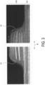
- FIG. 3 illustrates an example of a fillet FT obtained by performing the heat fusion using the resin dam 30.
- the fillet FT is formed on the side of the second joining body 103 on which the heater 21 is provided, and is continuously widened in a width direction W from the upper surface of the second joining body 103 toward the first joining body 101.
- the fillet FT is recessed in an arc shape at a boundary portion with the first joining body 101 and protrudes in an arc shape at an upper end of the second joining body 103 in the drawing.
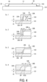
- the shape of the resin dam 30 described above is merely an example, and the present disclosure tolerates other resin dams 30. Among them, four examples (resin dams 30A to 30D) will be described with reference to FIGS. 4 and 5 .
- a depth D of the resin dam 30A which is a distance from the lower end 35A of the resin dam 30A to the base body 31, and a thickness T103 of the second joining body 103 have a relationship of D ⁇ T103. This relationship also true in the resin dams 30B to 30D described below.
- the thickness of the second joining body 103 is reduced after the heat fusion, and the gap G1 is determined in accordance with the degree of decrease in the thickness.
- a dam main body 33B is not inclined with respect to the side surface 103S but is parallel thereto. That is, the dam main body 33B of the resin dam 30B hangs down from the base body 31 at a right angle, and a shape control surface 34B is also parallel to the side surface 103S.
- a gap is provided between the dam main body 33B and the side surface 103S even at the upper end of the dam main body 33B, and the gap constitutes the resin pool RP.
- the dimension of the resin pool RP in the horizontal direction H is constant along the vertical direction V. Note that the dimensions of the resin pools RP in the resin dams 30A, 30C, and 30D in the horizontal direction H increase from the upper side toward the lower side in the vertical direction V.
- a shape control surface 34C of a dam main body 33C is formed of a rounded surface having an arc shape.
- the shape control surfaces 34A and 34B of the resin dams 30A and 30B are formed of flat surfaces.
- a lower end of the dam main body 33C which is continuous with the shape control surface 34 and faces the second joining body 103, is extended.
- This extended portion constitutes a pressing surface 35C having a flat shape that presses a region of the first joining body 101 to be melted by radiant heat and heat transfer during the heat fusion. The heat fusion is promoted by pressurization with the pressing surface 35C.
- the pressing surface 35C has a larger area to press the first joining body 101.
- the resin dam 30D has the same basic shape as the resin dam 30C. However, the volume of the resin pool RP is larger in the resin dam 30D than in the resin dam 30C. Thus, a base body 31D of the resin dam 30D is formed to have a larger plane area than the base body 31 of the resin dam 30C, and a gap G2 is provided from the side surface 103S of the second joining body 103 to the boundary between the base body 31 and the dam main body 33D.
- the amount of extrusion Ext. increases toward the center in a thickness direction T, and the shape of the extrusion Ext. includes large irregularities as illustrated in FIG. 7 .
- the extrusion cannot contribute to the strength and may fall off to cause contamination. Further, since the extrusion of the resin containing fibers occurs without restriction, the thickness of the second joining body 103 may be unexpectedly reduced.
- the shapes of extruded resins formed by the resin dams 30A to 30D are as illustrated in FIG. 5 , and the portions corresponding to the side surface 103S after the heat fusion are formed of smooth surfaces with less irregularities. That is, the side surface 103 S of the second joining body 103 formed by the resin dam 30A is a flat surface that is inclined with respect to the thickness direction of the first joining body 101 so as to follow the shape control surface 34A of the dam main body 33A.
- the side surface 103 S formed by the resin dam 30B is a flat surface that is parallel to the thickness direction so as to follow the shape control surface 34B of the dam main body 33B.
- the side surfaces 103S formed by the resin dams 30C and 30D have arc-shaped and rounded surfaces following the shape control surfaces 34C and 34D of the dam main bodies 33C and 33D, respectively.
- the shape of the extruded portion can be controlled, and thus there is no possibility of the extruded portion falling off.
- the extrusion amount of the resin containing fibers can also be controlled, and thus the reduction in the thickness can be suppressed as expected.
- the shapes of the extruded resins formed by the resin dams 30B to 30D are so-called fillets FT, and contribute to improvement of the joining strength between the first joining body 101 and the second joining body 103.
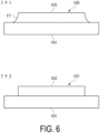
- the shear strength of a joined body 105 in which the side surface 103S of the second joining body 103 includes the fillet FT and the shear strength of a joined body 107 in which the side surface 103 S does not include the fillet FT were measured.
- the joined body 105 including the fillet FT had a higher shear strength than the joined body 107 by 9%.
- the present disclosure may be applied to a case in which the plane areas of two joining bodies are equal to each other.
- the resin dam is provided at a joining body on the side on which the heater is provided.
- the embodiment describes an example in which the first joining body 101 having a large plane area is disposed on the lower side and the second joining body 103 having a small plane area is disposed on the upper side, but in the present disclosure, a joining body having a small plane area may be disposed on the lower side, and a joining body having a large plane area may be disposed on the upper side. In that case, the joining body having a small plane area disposed on the lower side can be placed on the resin dam, and the heater can be disposed on the lower side of the resin dam.
- the heater is provided at only one of the two joining bodies, but the heater may be provided at both of the two joining bodies. In that case, the resin dam is provided at both of the two joining bodies.
- the joining method includes: a first step of layering a first joining body (101) and a second joining body (103) having a smaller plane area than the first joining body (101); and a second step of performing heating and pressurization with a heater (21) from a side of the second joining body (103).
- a resin dam (30) is interposed between the second joining body (103) and the heater (21).
- the resin dam (30) includes: a base body (31) having one of front and back surfaces in contact with the heater (21) and the other of front and back surfaces in contact with the second joining body (103); and a dam main body (33) extending from a circumferential edge (32) of the base body (31) in a direction away from the base body (31) and having a shape control surface (34) facing a side surface (103S) of the second joining body (103).
- a resin pool (RP) is provided between the shape control surface (34) and the side surface (103S).
- the shape control surface (34) is widened toward a direction away from the base body (31).
- the shape control surface (34) is rounded.
- an end portion (35A) of the dam main body (33) facing the first joining body (101) is separate from the first joining body (101), and a gap (G1) occurs between the first joining body (101) and the end portion (35A).
Landscapes
- Engineering & Computer Science (AREA)
- Mechanical Engineering (AREA)
- Physics & Mathematics (AREA)
- Thermal Sciences (AREA)
- Lining Or Joining Of Plastics Or The Like (AREA)
Abstract
Description
- The present disclosure relates to a method of joining thermoplastic composite members by heat fusion.
- For example, heat transfer fusion is known as a heat fusion technique for a thermoplastic composite member used as a structural material of an aircraft. In the heat transfer fusion, a heater is brought into contact with an outer surface of the thermoplastic composite member, heat generated by the heater is transferred to the inside of the material, and pressure is applied while melting a fusion interface until the melting point is exceeded. Typically, a thermoplastic composite member used as a structural material of an aircraft is made of carbon fiber reinforced thermoplastics (CFRTP).
- Since the temperature is increased to a temperature exceeding the melting point in a pressurized state during the heat fusion, fibers and a resin may be extruded outward from a circumferential edge of a member to be fused as illustrated in
FIG. 7 , for example. The plate thickness of the joined member with such extrusion is reduced more than desired, or the strength thereof is reduced because the fiber volume content (Vf) is reduced more than desired. In addition, the extruded portion interferes with other members and fails to assemble them in a subsequent process, or the extruded portion falls off and causes contamination. - For example,
Patent Document 1 discloses a molding die for a thermoplastic composite material. In the molding die, at least a part of a cavity formed by an upper die and a lower die is opened, and cooling fins are provided at end portions of the opened cavity so as to be continuous with a molding surface of each of the upper die and the lower die. -
Patent Document 2 proposes that, when thermoplastic plastics on which aluminum foil is laminated are caused to come into contact with each other and welded, first stage pressurizing compression is performed at a low pressure, and then second stage pressurizing compression is performed at a pressure higher than the pressure in the first stage pressurizing compression. -
- Patent Document 1:
JP H05-124042 A - Patent Document 2:
JP H11-1210 A -
Patent Document 1 relates to a technique for molding a single thermoplastic composite member and does not suggest heat fusion of two layered thermoplastic composite members. -
Patent Document 2 discloses heat fusion of two thermoplastic composite members. However, InPatent Document 2, thermoplastic plastic at a joined portion is pushed out to the inner side direction of a flange, a resin pool of the thermoplastic plastic is formed on the inner side, and the thermoplastic plastic is sealed, thereby obtaining a seal layer having a strong adhesive force. Therefore,Patent Document 2 does not suggest the above-described extrusion. - In view of the above, an object of the present disclosure is to control a shape of extrusion that occurs during heat fusion of two thermoplastic composite members.
- A joining method according to the present disclosure includes: a first step of layering a first joining body and a second joining body having a smaller plane area than the first joining body; and a second step of performing heating and pressurization with a heater from a side of the second joining body. In the second step, a resin dam is interposed between the second joining body and the heater.
- The resin dam includes: a base body having one of front and back surfaces in contact with the heater and the other of front and back surfaces in contact with the second joining body; and a dam main body extending from a circumferential edge of the base body in a direction away from the base body and having a shape control surface facing a side surface of the second joining body.
- The present disclosure can control, by performing heat fusion in a state where the resin dam is interposed between the second joining body and the heater, the shape of extrusion. Therefore, the present disclosure can reduce, even when extrusion occurs, adverse effects due to the extrusion.
-
-
FIG. 1 is a side view illustrating a configuration of an apparatus executing a heat fusion method according to an embodiment. -
FIG. 2 is a plan view illustrating the apparatus ofFIG. 1 . -
FIG. 3 is a diagram illustrating a joined body obtained by heat fusion of the embodiment. -
FIG. 4 is a diagram illustrating a plurality of modification examples included in the embodiment in a state before the heat fusion. -
FIG. 5 is a diagram illustrating the plurality of modification examples included in the embodiment in a state after the heat fusion. -
FIG. 6 illustrates joined bodies according to the embodiment, where the upper one includes a fillet and the lower one includes no fillet. -
FIG. 7 is a diagram illustrating an example of extrusion. - An embodiment will be described below with reference to the accompanying drawings.
- The embodiment relates to a method and an apparatus for joining thermoplastic composite materials, such as carbon fiber reinforced thermoplastic plastics (hereinafter CFRTP) by heat fusion. An object of the joining method according to the present embodiment is to reduce adverse effects due to extrusion of a resin by controlling, for example, a shape in which the resin containing fibers is extruded from a joined boundary portion of two CFRTP members.
- In the present embodiment, for example, a first joining
body 101 and a second joiningbody 103, each of which is made of CFRTP and has a flat shape, are joined by heat fusion. As illustrated in the drawing, the first joiningbody 101 and the second joiningbody 103 in the present embodiment are different from each other in a plane area which is an area in a planar direction, and the second joiningbody 103 is smaller than the first joiningbody 101. The second joiningbody 103 is placed on the first joiningbody 101, and a step occurs between the second joiningbody 103 and the first joiningbody 101. Although the details will be described below, a resin extrusion from the step portion occurs. The first joiningbody 101 and the second joiningbody 103 may be CFRTPs containing the same type of resin or may be CFRTPs containing different types of resins. Aside surface 101S of the first joiningbody 101 and aside surface 103S of the second joiningbody 103 extend along a vertical direction V. - The first joining
body 101 and the second joiningbody 103 are joined to each other by theheat fusion apparatus 1. - The
heat fusion apparatus 1 includes afirst element 10 provided on the lower side of the first joiningbody 101 and the second joiningbody 103 in the vertical direction V, and asecond element 20 provided on the upper side of the first joiningbody 101 and the second joiningbody 103 in the vertical direction V. In the case of the present embodiment, the second joiningbody 103 in contact with thesecond element 20 including aheater 21 is heated and melted so as to be heat-fused to the first joiningbody 101. - The
first element 10 includes a press platen 11 and aheat insulator 13 placed on the press platen 11. - The press platen 11 is required to have a rigidity enough to receive a load applied during the heat fusion and not to be deformed by the load. The press platen 11 is appropriately selected from, for example, a metal material and a ceramic material.
- The
heat insulator 13 is provided to suppress a decrease in the temperature of the first joiningbody 101 heated for the heat fusion. In order to achieve this object, preferably, theheat insulator 13 is made of a material having a low thermal conductivity, for example, 1.0 W/m · K or less, and has a heat resistance at a temperature of 400°C, and is made of, for example, a heat insulator containing glass fibers as a base material. The same applies to aheat insulator 23 of thesecond element 20. - The
second element 20 includes theheater 21, theheat insulator 23 placed on theheater 21, a pressurizingblock 25 placed on theheat insulator 23, and aresin dam 30 that controls the shape of the extruded resin. - The
heater 21 is appropriately selected from, for example, a sheet-like graphite heater that generates heat when supplied with electric power, a carbon heater using carbon fibers as a heat generator, a ceramic heater using alumina (Al2O3), silicon nitride (Si3N4), or the like as a heat generator, and a thin metal film heater. For the heat fusion of CFRTPs, it is desired that theheater 21 increases the temperature to a temperature of 400°C or higher. - The pressurizing
block 25 applies a load to the first joiningbody 101 and the second joiningbody 103 via theheater 21 and theheat insulator 23. - In the
heat fusion apparatus 1, joining by the heat fusion is performed through the first step and the second step performed after the first step described below. After the second step, cooling such as air cooling is performed. - First step: the first joining
body 101 and the second joiningbody 103 having a plane area smaller than the first joiningbody 101 are layered such that the second joiningbody 103 is on the upper side. - Second step: Heating and pressurization are performed by the
heater 21 from the side of the second joiningbody 103. - The
resin dam 30 includes abase body 31 having a flat rectangular shape in plan view, and a dammain body 33 projecting outward from acircumferential edge 32 of thebase body 31 and extending in a direction away from thebase body 31. Theresin dam 30 is integrally formed, for example, by press-forming a board made of copper or a copper alloy into thebase body 31 and the dammain body 33. Theresin dam 30 is provided on the side of the second joiningbody 103 to be heated and melted by theheater 21. - As will be described below, the
base body 31 is an element that applies heat and pressure necessary for joining the first joiningbody 101 and the second joiningbody 103 by the heat fusion. Thus, the amount of heat generated by theheater 21 is transmitted to the second joiningbody 103 particularly through thebase body 31 of theresin dam 30. Therefore, theresin dam 30 is made of, for example, a copper alloy having excellent thermal conductivity and small heat capacity. Considering that theresin dam 30 has a rigidity required to uniformly transmit a load by the pressurizingblock 25 to the second joiningbody 103 and the first joiningbody 101 in the planar direction and has a small decrease in strength due to softening even at an increased temperature of about 400 to 500°C, a metal material other than copper or a copper alloy, for example, an iron-based material such as steel or stainless steel or an Fe-Ni alloy can be used for theresin dam 30. - The dam
main body 33 is an element that controls the shape of an extruded resin. Since this resin is derived from CFRTP and thus contains fibers, the resin dam in the present disclosure refers to a member that controls the shape of the extruded resin containing fibers. - At a predetermined position at which the
resin dam 30 is held between theheater 21 and the second joiningbody 103, the dammain body 33 is inclined with respect to the vertical direction V. Thus, a gap is formed between the side surface 1035 of the second joiningbody 103 parallel to the vertical direction V and the dammain body 33. This gap has a shape whose dimension in the horizontal direction H increases from the upper side toward the lower side. Since the resin extruded from theside surface 103S of the second joiningbody 103 during the heat fusion stays in this gap, this gap is referred to as a resin pool RP. The shape of the extruded resin staying in the resin pool RP in the horizontal direction H follows the shape of ashape control surface 34 which is an inner side surface of the dammain body 33. In a cross-section in the vertical direction V, the extruded resin staying in the resin pool RP has a substantially triangular cross-sectional shape widening toward the lower side, similar to the shape of the resin pool RP. This shape can be regarded as a mechanical element called a fillet. Regarding the resin pool RP, only the extruded resin has been mentioned, but this resin is derived from CFRTP and thus contains fibers. That is, the resin pool RP in the present disclosure refers to a region in which the resin containing fibers is accumulated. -
FIG. 3 illustrates an example of a fillet FT obtained by performing the heat fusion using theresin dam 30. The fillet FT is formed on the side of the second joiningbody 103 on which theheater 21 is provided, and is continuously widened in a width direction W from the upper surface of the second joiningbody 103 toward the first joiningbody 101. The fillet FT is recessed in an arc shape at a boundary portion with the first joiningbody 101 and protrudes in an arc shape at an upper end of the second joiningbody 103 in the drawing. - The shape of the
resin dam 30 described above is merely an example, and the present disclosure toleratesother resin dams 30. Among them, four examples (resin dams 30A to 30D) will be described with reference toFIGS. 4 and5 . - First, in the
resin dam 30A, only an inner surface of a dammain body 33A is inclined with respect to theside surface 103S of the second joiningbody 103. The fillet FT illustrated inFIG. 3 can also be formed in theresin dam 30A. - In the
resin dam 30A, when thebase body 31 of theresin dam 30A is placed on the second joiningbody 103, alower end 35A of the dammain body 33A in the drawing is separate from the first joiningbody 101, and a gap G1 occurs between the first joiningbody 101 and thelower end 35A. That is, a depth D of theresin dam 30A, which is a distance from thelower end 35A of theresin dam 30A to thebase body 31, and a thickness T103 of the second joiningbody 103 have a relationship of D < T103. This relationship also true in theresin dams 30B to 30D described below. The thickness of the second joiningbody 103 is reduced after the heat fusion, and the gap G1 is determined in accordance with the degree of decrease in the thickness. - Next, in the
resin dam 30B, a dammain body 33B is not inclined with respect to theside surface 103S but is parallel thereto. That is, the dammain body 33B of theresin dam 30B hangs down from thebase body 31 at a right angle, and a shape control surface 34B is also parallel to theside surface 103S. A gap is provided between the dammain body 33B and theside surface 103S even at the upper end of the dammain body 33B, and the gap constitutes the resin pool RP. The dimension of the resin pool RP in the horizontal direction H is constant along the vertical direction V. Note that the dimensions of the resin pools RP in theresin dams - Next, in the
resin dam 30C, ashape control surface 34C of a dam main body 33C is formed of a rounded surface having an arc shape. Theshape control surfaces 34A and 34B of theresin dams - In addition, in the
resin dam 30C, a lower end of the dam main body 33C, which is continuous with theshape control surface 34 and faces the second joiningbody 103, is extended. This extended portion constitutes apressing surface 35C having a flat shape that presses a region of the first joiningbody 101 to be melted by radiant heat and heat transfer during the heat fusion. The heat fusion is promoted by pressurization with thepressing surface 35C. Note that, while theresin dams pressing surface 35C has a larger area to press the first joiningbody 101. - The
resin dam 30D has the same basic shape as theresin dam 30C. However, the volume of the resin pool RP is larger in theresin dam 30D than in theresin dam 30C. Thus, a base body 31D of theresin dam 30D is formed to have a larger plane area than thebase body 31 of theresin dam 30C, and a gap G2 is provided from theside surface 103S of the second joiningbody 103 to the boundary between thebase body 31 and the dammain body 33D. - When the second joining
body 103 is heat-fused to the first joiningbody 101 with theside surface 103S in a free state without using theresin dam 30A or the like, the amount of extrusion Ext. increases toward the center in a thickness direction T, and the shape of the extrusion Ext. includes large irregularities as illustrated inFIG. 7 . When the extrusion is formed in such a shape, the extrusion cannot contribute to the strength and may fall off to cause contamination. Further, since the extrusion of the resin containing fibers occurs without restriction, the thickness of the second joiningbody 103 may be unexpectedly reduced. - In the first joining
body 101 and the second joiningbody 103 joined by a heat fusion layer HF, the shapes of extruded resins formed by theresin dams 30A to 30D are as illustrated inFIG. 5 , and the portions corresponding to theside surface 103S after the heat fusion are formed of smooth surfaces with less irregularities. That is, theside surface 103 S of the second joiningbody 103 formed by theresin dam 30A is a flat surface that is inclined with respect to the thickness direction of the first joiningbody 101 so as to follow theshape control surface 34A of the dammain body 33A. Theside surface 103 S formed by theresin dam 30B is a flat surface that is parallel to the thickness direction so as to follow the shape control surface 34B of the dammain body 33B. The side surfaces 103S formed by theresin dams shape control surfaces main bodies 33C and 33D, respectively. - As described above, also in the present embodiment, although the extrusion occurs after the heat fusion, the shape of the extruded portion can be controlled, and thus there is no possibility of the extruded portion falling off. In addition, by controlling the shape of the extruded portion, the extrusion amount of the resin containing fibers can also be controlled, and thus the reduction in the thickness can be suppressed as expected.
- The shapes of the extruded resins formed by the
resin dams 30B to 30D are so-called fillets FT, and contribute to improvement of the joining strength between the first joiningbody 101 and the second joiningbody 103. For example, the shear strength of a joinedbody 105 in which theside surface 103S of the second joiningbody 103 includes the fillet FT and the shear strength of a joinedbody 107 in which theside surface 103 S does not include the fillet FT were measured. As a result, it was confirmed that the joinedbody 105 including the fillet FT had a higher shear strength than the joinedbody 107 by 9%. - Besides the above-described embodiment, configurations explained in the above-described embodiment can be selected or omitted as desired or can be changed to other configurations as necessary.
- For example, although an example in which the plane areas of two joining bodies are different from each other has been described in the embodiment, the present disclosure may be applied to a case in which the plane areas of two joining bodies are equal to each other. In that case, the resin dam is provided at a joining body on the side on which the heater is provided. The embodiment describes an example in which the first joining
body 101 having a large plane area is disposed on the lower side and the second joiningbody 103 having a small plane area is disposed on the upper side, but in the present disclosure, a joining body having a small plane area may be disposed on the lower side, and a joining body having a large plane area may be disposed on the upper side. In that case, the joining body having a small plane area disposed on the lower side can be placed on the resin dam, and the heater can be disposed on the lower side of the resin dam. - Further, in the embodiment, the heater is provided at only one of the two joining bodies, but the heater may be provided at both of the two joining bodies. In that case, the resin dam is provided at both of the two joining bodies.
- The joining method described in the embodiment is grasped as follows.
- The joining method includes: a first step of layering a first joining body (101) and a second joining body (103) having a smaller plane area than the first joining body (101); and a second step of performing heating and pressurization with a heater (21) from a side of the second joining body (103). In the second step, a resin dam (30) is interposed between the second joining body (103) and the heater (21). The resin dam (30) includes: a base body (31) having one of front and back surfaces in contact with the heater (21) and the other of front and back surfaces in contact with the second joining body (103); and a dam main body (33) extending from a circumferential edge (32) of the base body (31) in a direction away from the base body (31) and having a shape control surface (34) facing a side surface (103S) of the second joining body (103).
- In
Supplementary Note 1, preferably, a resin pool (RP) is provided between the shape control surface (34) and the side surface (103S). - In
Supplementary Note 1, preferably, the shape control surface (34) is widened toward a direction away from the base body (31). - In
Supplementary Note 1, preferably, the shape control surface (34) is rounded. - In
Supplementary Note 1, preferably, an end portion (35A) of the dam main body (33) facing the first joining body (101) is separate from the first joining body (101), and a gap (G1) occurs between the first joining body (101) and the end portion (35A). -
- 1 Heat fusion apparatus
- 10 First element
- 11 Press platen
- 13 Heat insulator
- 20 Second element
- 21 Heater
- 23 Heat insulator
- 25 Pressurizing block
- 30, 30A, 30B, 30C, 30D Resin dam
- 31 Base body
- 33 33A, 33B, 33C, 33D Dam main body
- 34 Shape control surface
- 35A Lower end
- 35C, 35D Pressing surface
- 101 First joining body
- 103 Second joining body
- 101S, 103S Side surface
- 105, 107 Joined body
- RP Resin pool
- FT Fillet
- H Horizontal direction
- V Vertical direction
- W Width direction
- G1, G2 Gap
Claims (5)
- A joining method using heat fusion, the joining method comprising:a first step of layering a first joining body and a second joining body having a smaller plane area than the first joining body; anda second step of performing heating and pressurization with a heater from a side of the second joining body, whereinin the second step, a resin dam is interposed between the second joining body and the heater, andthe resin dam includesa base body having one of front and back surfaces in contact with the heater and the other of front and back surfaces in contact with the second joining body anda dam main body extending from a circumferential edge of the base body in a direction away from the base body and having a shape control surface facing a side surface of the second joining body.
- The joining method according to claim 1, wherein a resin pool is provided between the shape control surface and the side surface.
- The joining method according to claim 1, wherein the shape control surface is widened toward a direction away from the base body.
- The joining method according to claim 1, wherein the shape control surface is rounded.
- The joining method according to claim 1, whereinan end portion of the dam main body facing the first joining body is separate from the first joining body, anda gap occurs between the first joining body and the end portion.
Applications Claiming Priority (1)
| Application Number | Priority Date | Filing Date | Title |
|---|---|---|---|
| JP2023147397A JP7834071B2 (en) | 2023-09-12 | 2023-09-12 | Joining method |
Publications (2)
| Publication Number | Publication Date |
|---|---|
| EP4523894A1 true EP4523894A1 (en) | 2025-03-19 |
| EP4523894B1 EP4523894B1 (en) | 2025-12-31 |
Family
ID=92424313
Family Applications (1)
| Application Number | Title | Priority Date | Filing Date |
|---|---|---|---|
| EP24194519.5A Active EP4523894B1 (en) | 2023-09-12 | 2024-08-14 | JOINING PROCESS |
Country Status (3)
| Country | Link |
|---|---|
| US (1) | US20250083396A1 (en) |
| EP (1) | EP4523894B1 (en) |
| JP (1) | JP7834071B2 (en) |
Citations (5)
| Publication number | Priority date | Publication date | Assignee | Title |
|---|---|---|---|---|
| JPH05124042A (en) | 1991-11-05 | 1993-05-21 | Toyobo Co Ltd | Mold for thermoplastic composite materials |
| JPH111210A (en) | 1997-04-17 | 1999-01-06 | Showa Alum Corp | Method for manufacturing laminated composite material container |
| US20070077397A1 (en) * | 2004-04-20 | 2007-04-05 | Tissage Et Enduction Serge Ferrari Sa | Bonding intermediate, method and machine for bonding coated textile sheets |
| EP2988920B1 (en) * | 2013-04-26 | 2020-03-04 | Bayerische Motoren Werke Aktiengesellschaft | Method for producing hybrid components |
| US20200298500A1 (en) * | 2019-03-19 | 2020-09-24 | The Boeing Company | Method and system for co-consolidation of thermoplastic composite material parts |
Family Cites Families (2)
| Publication number | Priority date | Publication date | Assignee | Title |
|---|---|---|---|---|
| JP5855401B2 (en) * | 2011-09-21 | 2016-02-09 | 三菱レイヨン株式会社 | Manufacturing method of fiber reinforced thermoplastic resin molded article |
| JP2018012108A (en) * | 2016-07-19 | 2018-01-25 | 三菱アルミニウム株式会社 | Press molding method of aluminum resin composite laminated plate |
-
2023
- 2023-09-12 JP JP2023147397A patent/JP7834071B2/en active Active
-
2024
- 2024-08-14 EP EP24194519.5A patent/EP4523894B1/en active Active
- 2024-08-27 US US18/815,850 patent/US20250083396A1/en active Pending
Patent Citations (5)
| Publication number | Priority date | Publication date | Assignee | Title |
|---|---|---|---|---|
| JPH05124042A (en) | 1991-11-05 | 1993-05-21 | Toyobo Co Ltd | Mold for thermoplastic composite materials |
| JPH111210A (en) | 1997-04-17 | 1999-01-06 | Showa Alum Corp | Method for manufacturing laminated composite material container |
| US20070077397A1 (en) * | 2004-04-20 | 2007-04-05 | Tissage Et Enduction Serge Ferrari Sa | Bonding intermediate, method and machine for bonding coated textile sheets |
| EP2988920B1 (en) * | 2013-04-26 | 2020-03-04 | Bayerische Motoren Werke Aktiengesellschaft | Method for producing hybrid components |
| US20200298500A1 (en) * | 2019-03-19 | 2020-09-24 | The Boeing Company | Method and system for co-consolidation of thermoplastic composite material parts |
Also Published As
| Publication number | Publication date |
|---|---|
| EP4523894B1 (en) | 2025-12-31 |
| JP7834071B2 (en) | 2026-03-23 |
| JP2025040540A (en) | 2025-03-25 |
| US20250083396A1 (en) | 2025-03-13 |
Similar Documents
| Publication | Publication Date | Title |
|---|---|---|
| CN104284750B (en) | Method for welding at least two layers | |
| EP3170587B1 (en) | Fibre-reinforced metal component for an aircraft or spacecraft and production methods for fibre-reinforced metal components | |
| CN103298593B (en) | The manufacturing installation of preform and manufacture method and the preform manufactured by the method | |
| US10471695B2 (en) | Methods and thermal structures for additive manufacturing | |
| CN105689912A (en) | Systems and methods for joining components | |
| US8603279B2 (en) | Process and device for welding a thermoplastic stiffener | |
| EP3936317A1 (en) | Frp molding system and method | |
| EP3747637A1 (en) | Method to integrate a first part and a second part comprising composite material | |
| JP5919066B2 (en) | Monolithic molded part manufacturing method and monolithic molded part | |
| EP4523894B1 (en) | JOINING PROCESS | |
| CN105150562B (en) | The pultrusion apparatus and its application method of staged curing degree rib | |
| US9919473B2 (en) | Method for producing fiber-reinforced resin bonded body | |
| US20250074009A1 (en) | Method for electromagnetic welding of molded parts and a heat sink for use in such method | |
| US12521915B2 (en) | Composite material processing apparatus and composite material processing method | |
| JP2021041634A (en) | Method for molding laminated composite sheet comprising fiber reinforced resin sheet and resin foamed sheet | |
| JP2020040369A (en) | Jig for thermal press bonding and method for manufacturing composite body | |
| JP2013212604A (en) | Method of manufacturing integrally molded part and integrally molded part | |
| KR20230054157A (en) | Method of hetrogeneous joint for cooling plate of battery pack | |
| US12629900B2 (en) | Method for actively cooling and supporting components during thermoplastic composite welding | |
| EP4501601A1 (en) | Method for actively cooling and supporting components during thermoplastic composite welding | |
| JP6690619B2 (en) | Metal-resin bonded body and method for manufacturing the same | |
| JP7825718B2 (en) | Composite material part manufacturing method and composite material part manufacturing device | |
| JP5914116B2 (en) | Monolithic molded part manufacturing method and monolithic molded part | |
| JP5902554B2 (en) | Insulating mold manufacturing method | |
| EP4219133A1 (en) | Method for surface structuring |
Legal Events
| Date | Code | Title | Description |
|---|---|---|---|
| PUAI | Public reference made under article 153(3) epc to a published international application that has entered the european phase |
Free format text: ORIGINAL CODE: 0009012 |
|
| STAA | Information on the status of an ep patent application or granted ep patent |
Free format text: STATUS: REQUEST FOR EXAMINATION WAS MADE |
|
| 17P | Request for examination filed |
Effective date: 20240814 |
|
| AK | Designated contracting states |
Kind code of ref document: A1 Designated state(s): AL AT BE BG CH CY CZ DE DK EE ES FI FR GB GR HR HU IE IS IT LI LT LU LV MC ME MK MT NL NO PL PT RO RS SE SI SK SM TR |
|
| GRAP | Despatch of communication of intention to grant a patent |
Free format text: ORIGINAL CODE: EPIDOSNIGR1 |
|
| STAA | Information on the status of an ep patent application or granted ep patent |
Free format text: STATUS: GRANT OF PATENT IS INTENDED |
|
| RIC1 | Information provided on ipc code assigned before grant |
Ipc: B29C 65/22 20060101AFI20250711BHEP Ipc: B29C 65/24 20060101ALI20250711BHEP Ipc: B29C 65/30 20060101ALI20250711BHEP Ipc: B29C 65/18 20060101ALI20250711BHEP Ipc: B29L 31/30 20060101ALN20250711BHEP |
|
| INTG | Intention to grant announced |
Effective date: 20250731 |
|
| GRAS | Grant fee paid |
Free format text: ORIGINAL CODE: EPIDOSNIGR3 |
|
| GRAA | (expected) grant |
Free format text: ORIGINAL CODE: 0009210 |
|
| STAA | Information on the status of an ep patent application or granted ep patent |
Free format text: STATUS: THE PATENT HAS BEEN GRANTED |
|
| AK | Designated contracting states |
Kind code of ref document: B1 Designated state(s): AL AT BE BG CH CY CZ DE DK EE ES FI FR GB GR HR HU IE IS IT LI LT LU LV MC ME MK MT NL NO PL PT RO RS SE SI SK SM TR |
|
| REG | Reference to a national code |
Ref country code: CH Ref legal event code: F10 Free format text: ST27 STATUS EVENT CODE: U-0-0-F10-F00 (AS PROVIDED BY THE NATIONAL OFFICE) Effective date: 20251231 Ref country code: GB Ref legal event code: FG4D |
|
| REG | Reference to a national code |
Ref country code: DE Ref legal event code: R096 Ref document number: 602024001929 Country of ref document: DE |
|
| REG | Reference to a national code |
Ref country code: IE Ref legal event code: FG4D |
|
| REG | Reference to a national code |
Ref country code: LT Ref legal event code: MG9D |
|
| PG25 | Lapsed in a contracting state [announced via postgrant information from national office to epo] |
Ref country code: NO Free format text: LAPSE BECAUSE OF FAILURE TO SUBMIT A TRANSLATION OF THE DESCRIPTION OR TO PAY THE FEE WITHIN THE PRESCRIBED TIME-LIMIT Effective date: 20260331 |
|
| PG25 | Lapsed in a contracting state [announced via postgrant information from national office to epo] |
Ref country code: HR Free format text: LAPSE BECAUSE OF FAILURE TO SUBMIT A TRANSLATION OF THE DESCRIPTION OR TO PAY THE FEE WITHIN THE PRESCRIBED TIME-LIMIT Effective date: 20251231 Ref country code: FI Free format text: LAPSE BECAUSE OF FAILURE TO SUBMIT A TRANSLATION OF THE DESCRIPTION OR TO PAY THE FEE WITHIN THE PRESCRIBED TIME-LIMIT Effective date: 20251231 |
|
| PG25 | Lapsed in a contracting state [announced via postgrant information from national office to epo] |
Ref country code: RS Free format text: LAPSE BECAUSE OF FAILURE TO SUBMIT A TRANSLATION OF THE DESCRIPTION OR TO PAY THE FEE WITHIN THE PRESCRIBED TIME-LIMIT Effective date: 20260331 |
|
| PG25 | Lapsed in a contracting state [announced via postgrant information from national office to epo] |
Ref country code: LV Free format text: LAPSE BECAUSE OF FAILURE TO SUBMIT A TRANSLATION OF THE DESCRIPTION OR TO PAY THE FEE WITHIN THE PRESCRIBED TIME-LIMIT Effective date: 20251231 |
|
| PG25 | Lapsed in a contracting state [announced via postgrant information from national office to epo] |
Ref country code: BG Free format text: LAPSE BECAUSE OF FAILURE TO SUBMIT A TRANSLATION OF THE DESCRIPTION OR TO PAY THE FEE WITHIN THE PRESCRIBED TIME-LIMIT Effective date: 20251231 |
|
| REG | Reference to a national code |
Ref country code: NL Ref legal event code: MP Effective date: 20251231 |