EP4523834A1 - Laser microjet device and method with in-line cameras - Google Patents
Laser microjet device and method with in-line cameras Download PDFInfo
- Publication number
- EP4523834A1 EP4523834A1 EP24192694.8A EP24192694A EP4523834A1 EP 4523834 A1 EP4523834 A1 EP 4523834A1 EP 24192694 A EP24192694 A EP 24192694A EP 4523834 A1 EP4523834 A1 EP 4523834A1
- Authority
- EP
- European Patent Office
- Prior art keywords
- cameras
- workpiece
- waterjet
- nozzle
- composite image
- Prior art date
- Legal status (The legal status is an assumption and is not a legal conclusion. Google has not performed a legal analysis and makes no representation as to the accuracy of the status listed.)
- Pending
Links
Images


Classifications
-
- B—PERFORMING OPERATIONS; TRANSPORTING
- B23—MACHINE TOOLS; METAL-WORKING NOT OTHERWISE PROVIDED FOR
- B23K—SOLDERING OR UNSOLDERING; WELDING; CLADDING OR PLATING BY SOLDERING OR WELDING; CUTTING BY APPLYING HEAT LOCALLY, e.g. FLAME CUTTING; WORKING BY LASER BEAM
- B23K26/00—Working by laser beam, e.g. welding, cutting or boring
- B23K26/14—Working by laser beam, e.g. welding, cutting or boring using a fluid stream, e.g. a jet of gas, in conjunction with the laser beam; Nozzles therefor
- B23K26/1462—Nozzles; Features related to nozzles
- B23K26/1464—Supply to, or discharge from, nozzles of media, e.g. gas, powder, wire
- B23K26/1476—Features inside the nozzle for feeding the fluid stream through the nozzle
-
- B—PERFORMING OPERATIONS; TRANSPORTING
- B23—MACHINE TOOLS; METAL-WORKING NOT OTHERWISE PROVIDED FOR
- B23K—SOLDERING OR UNSOLDERING; WELDING; CLADDING OR PLATING BY SOLDERING OR WELDING; CUTTING BY APPLYING HEAT LOCALLY, e.g. FLAME CUTTING; WORKING BY LASER BEAM
- B23K26/00—Working by laser beam, e.g. welding, cutting or boring
- B23K26/02—Positioning or observing the workpiece, e.g. with respect to the point of impact; Aligning, aiming or focusing the laser beam
- B23K26/03—Observing, e.g. monitoring, the workpiece
- B23K26/032—Observing, e.g. monitoring, the workpiece using optical means
-
- B—PERFORMING OPERATIONS; TRANSPORTING
- B23—MACHINE TOOLS; METAL-WORKING NOT OTHERWISE PROVIDED FOR
- B23K—SOLDERING OR UNSOLDERING; WELDING; CLADDING OR PLATING BY SOLDERING OR WELDING; CUTTING BY APPLYING HEAT LOCALLY, e.g. FLAME CUTTING; WORKING BY LASER BEAM
- B23K26/00—Working by laser beam, e.g. welding, cutting or boring
- B23K26/08—Devices involving relative movement between laser beam and workpiece
- B23K26/10—Devices involving relative movement between laser beam and workpiece using a fixed support, i.e. involving moving the laser beam
-
- B—PERFORMING OPERATIONS; TRANSPORTING
- B23—MACHINE TOOLS; METAL-WORKING NOT OTHERWISE PROVIDED FOR
- B23K—SOLDERING OR UNSOLDERING; WELDING; CLADDING OR PLATING BY SOLDERING OR WELDING; CUTTING BY APPLYING HEAT LOCALLY, e.g. FLAME CUTTING; WORKING BY LASER BEAM
- B23K26/00—Working by laser beam, e.g. welding, cutting or boring
- B23K26/14—Working by laser beam, e.g. welding, cutting or boring using a fluid stream, e.g. a jet of gas, in conjunction with the laser beam; Nozzles therefor
- B23K26/142—Working by laser beam, e.g. welding, cutting or boring using a fluid stream, e.g. a jet of gas, in conjunction with the laser beam; Nozzles therefor for the removal of by-products
-
- B—PERFORMING OPERATIONS; TRANSPORTING
- B23—MACHINE TOOLS; METAL-WORKING NOT OTHERWISE PROVIDED FOR
- B23K—SOLDERING OR UNSOLDERING; WELDING; CLADDING OR PLATING BY SOLDERING OR WELDING; CUTTING BY APPLYING HEAT LOCALLY, e.g. FLAME CUTTING; WORKING BY LASER BEAM
- B23K26/00—Working by laser beam, e.g. welding, cutting or boring
- B23K26/14—Working by laser beam, e.g. welding, cutting or boring using a fluid stream, e.g. a jet of gas, in conjunction with the laser beam; Nozzles therefor
- B23K26/146—Working by laser beam, e.g. welding, cutting or boring using a fluid stream, e.g. a jet of gas, in conjunction with the laser beam; Nozzles therefor the fluid stream containing a liquid
-
- B—PERFORMING OPERATIONS; TRANSPORTING
- B23—MACHINE TOOLS; METAL-WORKING NOT OTHERWISE PROVIDED FOR
- B23K—SOLDERING OR UNSOLDERING; WELDING; CLADDING OR PLATING BY SOLDERING OR WELDING; CUTTING BY APPLYING HEAT LOCALLY, e.g. FLAME CUTTING; WORKING BY LASER BEAM
- B23K26/00—Working by laser beam, e.g. welding, cutting or boring
- B23K26/36—Removing material
- B23K26/362—Laser etching
-
- B—PERFORMING OPERATIONS; TRANSPORTING
- B23—MACHINE TOOLS; METAL-WORKING NOT OTHERWISE PROVIDED FOR
- B23K—SOLDERING OR UNSOLDERING; WELDING; CLADDING OR PLATING BY SOLDERING OR WELDING; CUTTING BY APPLYING HEAT LOCALLY, e.g. FLAME CUTTING; WORKING BY LASER BEAM
- B23K26/00—Working by laser beam, e.g. welding, cutting or boring
- B23K26/36—Removing material
- B23K26/38—Removing material by boring or cutting
- B23K26/382—Removing material by boring or cutting by boring
-
- B—PERFORMING OPERATIONS; TRANSPORTING
- B23—MACHINE TOOLS; METAL-WORKING NOT OTHERWISE PROVIDED FOR
- B23K—SOLDERING OR UNSOLDERING; WELDING; CLADDING OR PLATING BY SOLDERING OR WELDING; CUTTING BY APPLYING HEAT LOCALLY, e.g. FLAME CUTTING; WORKING BY LASER BEAM
- B23K26/00—Working by laser beam, e.g. welding, cutting or boring
- B23K26/36—Removing material
- B23K26/40—Removing material taking account of the properties of the material involved
- B23K26/402—Removing material taking account of the properties of the material involved involving non-metallic material, e.g. isolators
-
- B—PERFORMING OPERATIONS; TRANSPORTING
- B23—MACHINE TOOLS; METAL-WORKING NOT OTHERWISE PROVIDED FOR
- B23K—SOLDERING OR UNSOLDERING; WELDING; CLADDING OR PLATING BY SOLDERING OR WELDING; CUTTING BY APPLYING HEAT LOCALLY, e.g. FLAME CUTTING; WORKING BY LASER BEAM
- B23K26/00—Working by laser beam, e.g. welding, cutting or boring
- B23K26/70—Auxiliary operations or equipment
-
- G—PHYSICS
- G06—COMPUTING OR CALCULATING; COUNTING
- G06T—IMAGE DATA PROCESSING OR GENERATION, IN GENERAL
- G06T7/00—Image analysis
- G06T7/0002—Inspection of images, e.g. flaw detection
- G06T7/0004—Industrial image inspection
-
- G—PHYSICS
- G06—COMPUTING OR CALCULATING; COUNTING
- G06T—IMAGE DATA PROCESSING OR GENERATION, IN GENERAL
- G06T7/00—Image analysis
- G06T7/97—Determining parameters from multiple pictures
-
- H—ELECTRICITY
- H04—ELECTRIC COMMUNICATION TECHNIQUE
- H04N—PICTORIAL COMMUNICATION, e.g. TELEVISION
- H04N23/00—Cameras or camera modules comprising electronic image sensors; Control thereof
- H04N23/90—Arrangement of cameras or camera modules, e.g. multiple cameras in TV studios or sports stadiums
-
- B—PERFORMING OPERATIONS; TRANSPORTING
- B23—MACHINE TOOLS; METAL-WORKING NOT OTHERWISE PROVIDED FOR
- B23K—SOLDERING OR UNSOLDERING; WELDING; CLADDING OR PLATING BY SOLDERING OR WELDING; CUTTING BY APPLYING HEAT LOCALLY, e.g. FLAME CUTTING; WORKING BY LASER BEAM
- B23K2103/00—Materials to be soldered, welded or cut
- B23K2103/16—Composite materials
-
- B—PERFORMING OPERATIONS; TRANSPORTING
- B23—MACHINE TOOLS; METAL-WORKING NOT OTHERWISE PROVIDED FOR
- B23K—SOLDERING OR UNSOLDERING; WELDING; CLADDING OR PLATING BY SOLDERING OR WELDING; CUTTING BY APPLYING HEAT LOCALLY, e.g. FLAME CUTTING; WORKING BY LASER BEAM
- B23K2103/00—Materials to be soldered, welded or cut
- B23K2103/50—Inorganic materials other than metals or composite materials
- B23K2103/52—Ceramics
-
- G—PHYSICS
- G06—COMPUTING OR CALCULATING; COUNTING
- G06T—IMAGE DATA PROCESSING OR GENERATION, IN GENERAL
- G06T2207/00—Indexing scheme for image analysis or image enhancement
- G06T2207/30—Subject of image; Context of image processing
- G06T2207/30108—Industrial image inspection
- G06T2207/30164—Workpiece; Machine component
Definitions
- CMCs are extremely hard and brittle and can therefore be hard to machine efficiently.
- Waterjet guided laser (i.e., laser microjet) technology is considered a promising manufacturing route for producing complex 3D holes in CMC parts. This technology works by transmitting a laser through a high-pressure water column to the surface of the part. Locating the waterjet nozzle to the part or fixture is accomplished by use of a retractable touch probe, off-set camera, or the water column itself.
- a retractable touch probe, off-set camera, or the water column itself is used by use of a retractable touch probe, off-set camera, or the water column itself.
- alignment via the touch probe and/or camera can be difficult due to physical interference between parts, especially those with nonplanar surfaces, and the nozzle head assembly. Thus, alternative means of alignment are desirable.
- a device for forming a feature in a workpiece includes a waterjet guided laser device translatable relative to the workpiece.
- the waterjet guided laser device includes a head assembly having a nozzle comprising an aperture for ejecting a waterjet with an internal laser beam, and a camera system comprising a plurality of cameras disposed about the nozzle.
- a method of forming a feature in a workpiece includes orienting a waterjet guided laser device about the workpiece by capturing a plurality of images of the workpiece with a corresponding plurality of cameras, generating a composite image from the plurality of images, and aligning a nozzle of the waterjet guided laser device to the workpiece based on the composite image.
- the method further includes ejecting a waterjet from an aperture of the nozzle, and impinging the waterjet against the workpiece causing a corresponding removal of material therefrom.
- This disclosure presents means for aligning a waterjet nozzle aperture with a workpiece using an in-line camera system.
- the camera system includes multiple cameras disposed about the waterjet nozzle.
- Such a system can generate a composite image surrounding the nozzle to help center the nozzle aperture, and thereby the water column, over a feature of the workpiece surface.
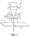
- FIG. 1 is a simplified illustration of waterjet guided laser device 10.
- Device 10 includes laser beam 12 from a laser source, focusing lens 14, window 16, pressurized water chamber 18, and nozzle 20. Nozzle 20 can be disposed within head assembly 22.
- laser beam 12 is focused by focusing lens 14 and window 16 as it reaches pressurized water chamber 18, which is filled with pressurized water.
- Cylindrical waterjet (i.e., water column) 24 with internally reflected laser beam 12 is ejected from nozzle 20 and impinges upon workpiece 26 causing removal of workpiece material along a predetermined tool path.
- Workpiece 26 can be a CMC part, such as an airfoil, platform, blade outer air seal (BOAS), etc., having one or a combination of planar and curved outer surfaces 28.
- Device 10 can be translatable along multiple axes with respect to workpiece 26.
- Workpiece 26 can be mounted on a rotatable or otherwise translatable base (not shown) to facilitate access to and alignment of outer surfaces 28.
- FIG. 2 is a simplified close-up view of head assembly 22, including touch probe 30 and camera system 32.
- FIG. 3 is a simplified bottom plan view of camera system 32, including multiple cameras 34. FIGS. 2 and 3 are discussed together.
- Head assembly 22 can include nozzle 20, camera system 32 collocated with nozzle 20, and touch probe 30.
- Nozzle 20 can include aperture 36 having an aperture diameter D1.
- Aperture 36 controls the diameter of ejected cylindrical waterjet 24, represented in FIG. 2 with dashed lines.
- Diameter D1 can range from 50 microns to 100 microns, and can be 70 microns in an exemplary embodiment.
- Touch probe 30 can be used to help align head assembly 22 with workpiece 26 for establishing a work coordinate system (WCS) used as a starting point for operation of system 10. Touch probe 30 can additionally and/or alternatively be used to insure the proper stand-off distance from surface 28 of workpiece 26.
- WCS work coordinate system
- Touch probe 30 can be retractable and extendable relative to recess 38 within head assembly 22 such that touch probe 30 does not impede the multiaxial translation of head assembly 22 relative to workpiece 26. Touch probe can be offset from nozzle 20 a greater distance than cameras 34, which is discussed in greater detail below.
- Camera system 32 can include at least one, and preferably, two to ten cameras 34 disposed about and proximate nozzle 20.
- camera system 32 can include four to eight cameras 34.
- FIG. 3 camera system 32 includes four cameras 34 disposed generally equidistant from one another about nozzle 20.
- Four additional and optional cameras 34 are shown in dashed lines, as an alternative embodiment can include eight cameras 34.
- Cameras 34 can be generally flush with the lowest (i.e., downstream) surface of nozzle 20 such that each camera 34 can be offset from outer surface 28 a distance, or length L1 ( FIG. 2 ), which is generally equal to the length of the cylindrical waterjet 24 after exiting nozzle 20 until reaching outer surface 28.
- Length L1 can range from 0.5 in (12.7 mm) to 1.5 in (38.1 mm) and can scale with diameter D1 of aperture 36. For example, in an embodiment with a diameter D1 of 70 microns, length L1 can be 0.75 in (19 mm). In general, length L1 will be the same for each camera 34 within system 32. In an alternative embodiment, each camera 34 can be partially to fully external to head assembly 22 (i.e., being relatively closer to workpiece 26 with respect to nozzle 20) such that L1 is less than the length of cylindrical waterjet 24.
- Each camera 34 can be oriented in the direction of workpiece 26 for capturing an image of surface 28.
- Camera system 32 can further include processing device 40 in communication with each camera 34.
- Processing device 40 can include one or more field programmable gate arrays (FPGA), an application specific integrated circuits (ASIC), or microprocessors for performing image processing (e.g., cropping, scaling, etc.) as well as forming a composite image from the individual image of each camera 34.
- the composite image can be displayed on display 42 which can be associated with device 10.
- each camera 34 can include a filter selective to the wavelength of laser beam 12 ( FIG. 1 ) to allow cameras 34 to use optical information from laser beam 12 to further improve accuracy of alignment. Filters can additionally and/or alternatively filter wavelengths which otherwise might interfere with cameras 34.
- one or more features 44 can be formed in workpiece 26.
- features 44 can be metering holes.
- workpiece 26 can be removed from its base for inspection, and such inspection might reveal imperfections in one or more features 44, such as an incomplete drill through the thickness of workpiece 26. In such case, the one or more features 44 can be considered incomplete and/or partially-formed features 44.
- Workpiece 26 can be remounted to its base for redrilling, however, it can be challenging to align nozzle 20 and aperture 36 to particularly small features 44, such as a metering hole, using just touch probe 30 and/or a single camera 34 proximate nozzle 20.
- surface obstructions 46 such as a boss or other objected projecting away from outer surface 28 can interfere with the translation of head assembly 22 when attempting such an alignment.
- Camera system 32 with its multiple cameras 34 and composite imaging capabilities advantageously allow for a more precise alignment of aperture 36, and thereby cylindrical waterjet 24, with feature 44 for further drilling.
- Camera system 32 can additionally and/or alternatively be used for positioning of nozzle 20 during the initial drilling operation to establish the starting point of the WCS.
- a small amount of material can be removed from outer surface 28 by briefly pulsing of cylindrical waterjet 24 prior to drilling/redrilling. This can create a visibly high-contrast region with which to confirm proper alignment.
- the disclosed waterjet guided laser device can be used to form features in CMC components for use in aerospace, maritime, or industrial equipment, to name a few, non-limiting examples.
- a device for forming a feature in a workpiece includes a waterjet guided laser device translatable relative to the workpiece.
- the waterjet guided laser device includes a head assembly having a nozzle comprising an aperture for ejecting a waterjet with an internal laser beam, and a camera system comprising a plurality of cameras disposed about the nozzle.
- the head assembly can further include a retractable touch probe.
- the aperture can have a diameter ranging from 50 microns to 100 microns.
- the diameter can be 70 microns.
- the camera system can include two cameras to ten cameras.
- the camera system can include four cameras.
- each of the plurality of cameras can be configured to capture a corresponding plurality of images of a workpiece.
- Any of the above devices can further include a display for displaying the composite image.
- a method of forming a feature in a workpiece includes orienting a waterjet guided laser device about the workpiece by capturing a plurality of images of the workpiece with a corresponding plurality of cameras, generating a composite image from the plurality of images, and aligning a nozzle of the waterjet guided laser device to the workpiece based on the composite image.
- the method further includes ejecting a waterjet from an aperture of the nozzle, and impinging the waterjet against the workpiece causing a corresponding removal of material therefrom.
- each of the plurality of cameras can be disposed about the nozzle.
- Any of the above methods can further include positioning the waterjet guided laser device such that the plurality of cameras are offset a distance from the workpiece.
- the distance can range from 0.5 in to 1.5 in.
- the aperture can have a diameter ranging from 50 microns to 100 microns.
- the plurality of cameras can include two cameras to ten cameras.
- the plurality of cameras can include four cameras to eight cameras.
- Any of the above methods can further include displaying the composite image on a display.
- a processing device can generate the composite image.
- the step of impinging the waterjet against the workpiece can include impinging the waterjet against a partially formed feature in the workpiece.
Landscapes
- Engineering & Computer Science (AREA)
- Physics & Mathematics (AREA)
- Optics & Photonics (AREA)
- Plasma & Fusion (AREA)
- Mechanical Engineering (AREA)
- Computer Vision & Pattern Recognition (AREA)
- General Physics & Mathematics (AREA)
- Theoretical Computer Science (AREA)
- Quality & Reliability (AREA)
- Multimedia (AREA)
- Signal Processing (AREA)
- Laser Beam Processing (AREA)
Abstract
Description
- The present invention relates to ceramic matrix composites (CMCs), and more particularly, to means of machining CMCs.
- CMCs are extremely hard and brittle and can therefore be hard to machine efficiently. Waterjet guided laser (i.e., laser microjet) technology is considered a promising manufacturing route for producing complex 3D holes in CMC parts. This technology works by transmitting a laser through a high-pressure water column to the surface of the part. Locating the waterjet nozzle to the part or fixture is accomplished by use of a retractable touch probe, off-set camera, or the water column itself. However, with particularly small holes and/or features, alignment via the touch probe and/or camera can be difficult due to physical interference between parts, especially those with nonplanar surfaces, and the nozzle head assembly. Thus, alternative means of alignment are desirable.
- A device for forming a feature in a workpiece includes a waterjet guided laser device translatable relative to the workpiece. The waterjet guided laser device includes a head assembly having a nozzle comprising an aperture for ejecting a waterjet with an internal laser beam, and a camera system comprising a plurality of cameras disposed about the nozzle.
- A method of forming a feature in a workpiece includes orienting a waterjet guided laser device about the workpiece by capturing a plurality of images of the workpiece with a corresponding plurality of cameras, generating a composite image from the plurality of images, and aligning a nozzle of the waterjet guided laser device to the workpiece based on the composite image. The method further includes ejecting a waterjet from an aperture of the nozzle, and impinging the waterjet against the workpiece causing a corresponding removal of material therefrom.
-
-
FIG. 1 is a simplified illustration of a waterjet guided laser device. -
FIG. 2 is a simplified close-up view of a head assembly of the waterjet guided laser device. -
FIG. 3 is a simplified bottom plan view of a camera system of the waterjet guided laser device. - While the above-identified figures set forth one or more embodiments of the present disclosure, other embodiments are also contemplated, as noted in the discussion. In all cases, this disclosure presents the invention by way of representation and not limitation. It should be understood that numerous other modifications and embodiments can be devised by those skilled in the art, which fall within the scope and spirit of the principles of the invention. The figures may not be drawn to scale, and applications and embodiments of the present invention may include features and components not specifically shown in the drawings.
- This disclosure presents means for aligning a waterjet nozzle aperture with a workpiece using an in-line camera system. The camera system includes multiple cameras disposed about the waterjet nozzle. Such a system can generate a composite image surrounding the nozzle to help center the nozzle aperture, and thereby the water column, over a feature of the workpiece surface.
-
FIG. 1 is a simplified illustration of waterjet guidedlaser device 10.Device 10 includeslaser beam 12 from a laser source, focusinglens 14,window 16, pressurizedwater chamber 18, andnozzle 20.Nozzle 20 can be disposed withinhead assembly 22. In operation,laser beam 12 is focused by focusinglens 14 andwindow 16 as it reaches pressurizedwater chamber 18, which is filled with pressurized water. Cylindrical waterjet (i.e., water column) 24 with internally reflectedlaser beam 12 is ejected fromnozzle 20 and impinges uponworkpiece 26 causing removal of workpiece material along a predetermined tool path.Workpiece 26 can be a CMC part, such as an airfoil, platform, blade outer air seal (BOAS), etc., having one or a combination of planar and curvedouter surfaces 28.Device 10 can be translatable along multiple axes with respect toworkpiece 26.Workpiece 26 can be mounted on a rotatable or otherwise translatable base (not shown) to facilitate access to and alignment ofouter surfaces 28. -
FIG. 2 is a simplified close-up view ofhead assembly 22, includingtouch probe 30 andcamera system 32.FIG. 3 is a simplified bottom plan view ofcamera system 32, includingmultiple cameras 34.FIGS. 2 and3 are discussed together. -
Head assembly 22 can includenozzle 20,camera system 32 collocated withnozzle 20, andtouch probe 30. Nozzle 20 can includeaperture 36 having an aperture diameter D1.Aperture 36 controls the diameter of ejectedcylindrical waterjet 24, represented inFIG. 2 with dashed lines. Diameter D1 can range from 50 microns to 100 microns, and can be 70 microns in an exemplary embodiment.Touch probe 30 can be used to help alignhead assembly 22 withworkpiece 26 for establishing a work coordinate system (WCS) used as a starting point for operation ofsystem 10.Touch probe 30 can additionally and/or alternatively be used to insure the proper stand-off distance fromsurface 28 ofworkpiece 26.Touch probe 30 can be retractable and extendable relative torecess 38 withinhead assembly 22 such thattouch probe 30 does not impede the multiaxial translation ofhead assembly 22 relative toworkpiece 26. Touch probe can be offset from nozzle 20 a greater distance thancameras 34, which is discussed in greater detail below. -
Camera system 32 can include at least one, and preferably, two to tencameras 34 disposed about andproximate nozzle 20. In an exemplary embodiment,camera system 32 can include four to eightcameras 34. As shown inFIG. 3 ,camera system 32 includes fourcameras 34 disposed generally equidistant from one another aboutnozzle 20. Four additional andoptional cameras 34 are shown in dashed lines, as an alternative embodiment can include eightcameras 34.Cameras 34 can be generally flush with the lowest (i.e., downstream) surface ofnozzle 20 such that eachcamera 34 can be offset from outer surface 28 a distance, or length L1 (FIG. 2 ), which is generally equal to the length of thecylindrical waterjet 24 after exitingnozzle 20 until reachingouter surface 28. Length L1 can range from 0.5 in (12.7 mm) to 1.5 in (38.1 mm) and can scale with diameter D1 ofaperture 36. For example, in an embodiment with a diameter D1 of 70 microns, length L1 can be 0.75 in (19 mm). In general, length L1 will be the same for eachcamera 34 withinsystem 32. In an alternative embodiment, eachcamera 34 can be partially to fully external to head assembly 22 (i.e., being relatively closer toworkpiece 26 with respect to nozzle 20) such that L1 is less than the length ofcylindrical waterjet 24. - Each
camera 34 can be oriented in the direction ofworkpiece 26 for capturing an image ofsurface 28.Camera system 32 can further includeprocessing device 40 in communication with eachcamera 34.Processing device 40 can include one or more field programmable gate arrays (FPGA), an application specific integrated circuits (ASIC), or microprocessors for performing image processing (e.g., cropping, scaling, etc.) as well as forming a composite image from the individual image of eachcamera 34. The composite image can be displayed ondisplay 42 which can be associated withdevice 10. In some embodiments, eachcamera 34 can include a filter selective to the wavelength of laser beam 12 (FIG. 1 ) to allowcameras 34 to use optical information fromlaser beam 12 to further improve accuracy of alignment. Filters can additionally and/or alternatively filter wavelengths which otherwise might interfere withcameras 34. - In operation of
device 10, one or more features 44 (FIG. 2 ) can be formed inworkpiece 26. In one embodiment,features 44 can be metering holes. In some cases,workpiece 26 can be removed from its base for inspection, and such inspection might reveal imperfections in one ormore features 44, such as an incomplete drill through the thickness ofworkpiece 26. In such case, the one ormore features 44 can be considered incomplete and/or partially-formedfeatures 44.Workpiece 26 can be remounted to its base for redrilling, however, it can be challenging to alignnozzle 20 and aperture 36 to particularlysmall features 44, such as a metering hole, using justtouch probe 30 and/or asingle camera 34proximate nozzle 20. Further,surface obstructions 46, such as a boss or other objected projecting away fromouter surface 28 can interfere with the translation ofhead assembly 22 when attempting such an alignment.Camera system 32 with itsmultiple cameras 34 and composite imaging capabilities advantageously allow for a more precise alignment ofaperture 36, and therebycylindrical waterjet 24, withfeature 44 for further drilling.Camera system 32 can additionally and/or alternatively be used for positioning ofnozzle 20 during the initial drilling operation to establish the starting point of the WCS. In some cases, a small amount of material can be removed fromouter surface 28 by briefly pulsing ofcylindrical waterjet 24 prior to drilling/redrilling. This can create a visibly high-contrast region with which to confirm proper alignment. - The disclosed waterjet guided laser device can be used to form features in CMC components for use in aerospace, maritime, or industrial equipment, to name a few, non-limiting examples.
- The following are non-exclusive descriptions of possible embodiments of the present invention.
- A device for forming a feature in a workpiece includes a waterjet guided laser device translatable relative to the workpiece. The waterjet guided laser device includes a head assembly having a nozzle comprising an aperture for ejecting a waterjet with an internal laser beam, and a camera system comprising a plurality of cameras disposed about the nozzle.
- The device of the preceding paragraph can optionally include, additionally and/or alternatively, any one or more of the following features, configurations and/or additional components:
In the above device, the head assembly can further include a retractable touch probe. - In any of the above devices, the aperture can have a diameter ranging from 50 microns to 100 microns.
- In any of the above devices, the diameter can be 70 microns.
- In any of the above devices, the camera system can include two cameras to ten cameras.
- In any of the above devices, the camera system can include four cameras to eight cameras.
- In any of the above devices, the camera system can include four cameras.
- In any of the above devices, each of the plurality of cameras can be configured to capture a corresponding plurality of images of a workpiece.
- In any of the above devices, the camera system can further include a processing device for generating a composite image from the plurality of images.
- Any of the above devices can further include a display for displaying the composite image.
- A method of forming a feature in a workpiece includes orienting a waterjet guided laser device about the workpiece by capturing a plurality of images of the workpiece with a corresponding plurality of cameras, generating a composite image from the plurality of images, and aligning a nozzle of the waterjet guided laser device to the workpiece based on the composite image. The method further includes ejecting a waterjet from an aperture of the nozzle, and impinging the waterjet against the workpiece causing a corresponding removal of material therefrom.
- The method of the preceding paragraph can optionally include, additionally and/or alternatively, any one or more of the following features, configurations and/or additional steps:
In the above method, each of the plurality of cameras can be disposed about the nozzle. - Any of the above methods can further include positioning the waterjet guided laser device such that the plurality of cameras are offset a distance from the workpiece.
- In any of the above methods, the distance can range from 0.5 in to 1.5 in.
- In any of the above methods, the aperture can have a diameter ranging from 50 microns to 100 microns.
- In any of the above methods, the plurality of cameras can include two cameras to ten cameras.
- In any of the above methods, the plurality of cameras can include four cameras to eight cameras.
- Any of the above methods can further include displaying the composite image on a display.
- In any of the above methods, a processing device can generate the composite image.
- In any of the above methods, the step of impinging the waterjet against the workpiece can include impinging the waterjet against a partially formed feature in the workpiece.
- While the invention has been described with reference to an exemplary embodiment(s), it will be understood by those skilled in the art that various changes may be made and equivalents may be substituted for elements thereof without departing from the scope of the invention. In addition, many modifications may be made to adapt a particular situation or material to the teachings of the invention without departing from the essential scope thereof. Therefore, it is intended that the invention not be limited to the particular embodiment(s) disclosed, but that the invention will include all embodiments falling within the scope of the appended claims.
Claims (15)
- A device (10) for forming a feature (44) in a workpiece (26), the device (10) comprising:
a waterjet guided laser device (10) translatable relative to the workpiece (26), the waterjet guided laser device (10) comprising:
a head assembly (22) comprising:a nozzle (20) comprising an aperture (36) for ejecting a waterjet (24) with an internal laser beam (12); anda camera system (32) comprising a plurality of cameras (34) disposed about the nozzle (20). - The device (10) of claim 1, wherein the head assembly (22) further comprises: a retractable touch probe (30).
- The device (10) of claim 1 or 2, wherein the camera system (32) comprises two cameras to ten cameras (34),
wherein, optionally, the camera system (32) comprises four cameras to eight cameras (34). - The device (10) of claim 1, 2 or 3, wherein each of the plurality of cameras (34) is configured to capture a corresponding plurality of images of a workpiece (26).
- The device (10) of claim 4, wherein the camera system (32) further comprises: a processing device (40) for generating a composite image from the plurality of images.
- The device (10) of claim 5, and further comprising: a display (42) for displaying the composite image.
- A method of forming a feature (44) in a workpiece (26), the method comprising:orienting a waterjet guided laser device (10) about the workpiece (26) by:capturing a plurality of images of the workpiece (26) with a corresponding plurality of cameras (34);generating a composite image from the plurality of images; andaligning a nozzle (20) of the waterjet guided laser device (10) to the workpiece (26) based on the composite image;ejecting a waterjet (24) from an aperture (36) of the nozzle (20); andimpinging the waterjet (24) against the workpiece (26) causing a corresponding removal of material therefrom.
- The method of claim 7, wherein each of the plurality of cameras (34) is disposed about the nozzle (20).
- The method of claim 7 or 8, and further comprising: positioning the waterjet guided laser device (10) such that the plurality of cameras (34) are offset a distance (L1) from the workpiece (26).
- The method of claim 9, wherein the distance (L1) ranges from 0.5 in (12.7mm) to 1.5 in (38.1mm).
- The method of any of claims 7 to 10, wherein the plurality of cameras (34) comprises two cameras to ten cameras (34),
wherein, optionally, the plurality of cameras (34) comprises four cameras to eight cameras (34). - The method of any of claims 7 to 11, and further comprising: displaying the composite image on a display (42).
- The method of any of claims 7 to 12, wherein a processing device (40) generates the composite image.
- The method of any of claims 7 to 13, wherein the step of impinging the waterjet (24) against the workpiece (26) comprises impinging the waterjet (24) against a partially formed feature (44) in the workpiece (26).
- The device (10) or method of any preceding claim, wherein the aperture (36) has a diameter (D1) ranging from 50 microns to 100 microns,
wherein, optionally, the diameter (D1) is 70 microns.
Applications Claiming Priority (1)
| Application Number | Priority Date | Filing Date | Title |
|---|---|---|---|
| US18/229,803 US20250041968A1 (en) | 2023-08-03 | 2023-08-03 | Laser microjet with in-line camera |
Publications (1)
| Publication Number | Publication Date |
|---|---|
| EP4523834A1 true EP4523834A1 (en) | 2025-03-19 |
Family
ID=92212796
Family Applications (1)
| Application Number | Title | Priority Date | Filing Date |
|---|---|---|---|
| EP24192694.8A Pending EP4523834A1 (en) | 2023-08-03 | 2024-08-02 | Laser microjet device and method with in-line cameras |
Country Status (2)
| Country | Link |
|---|---|
| US (1) | US20250041968A1 (en) |
| EP (1) | EP4523834A1 (en) |
Citations (4)
| Publication number | Priority date | Publication date | Assignee | Title |
|---|---|---|---|---|
| DE19852302A1 (en) * | 1998-11-12 | 2000-05-25 | Fraunhofer Ges Forschung | Method and device for processing workpieces with high-energy radiation |
| DE102016007586A1 (en) * | 2016-06-21 | 2017-12-21 | QuISS Qualitäts-Inspektionssysteme und Service AG | Novel device / s for automatically applying or generating and monitoring a structure applied to a substrate with determination of geometric dimensions and a corresponding method |
| US20170361399A1 (en) * | 2015-01-30 | 2017-12-21 | Makino Milling Machine Co., Ltd. | Laser beam machine and alignment adjusting method |
| US20180161928A1 (en) * | 2016-12-08 | 2018-06-14 | General Electric Company | Method and System for Confined Laser Cutting |
Family Cites Families (2)
| Publication number | Priority date | Publication date | Assignee | Title |
|---|---|---|---|---|
| US20050205778A1 (en) * | 2003-10-17 | 2005-09-22 | Gsi Lumonics Corporation | Laser trim motion, calibration, imaging, and fixturing techniques |
| CH700111B1 (en) * | 2009-09-25 | 2010-06-30 | Agie Sa | Machine for making three-dimensional workpiece using focused beam of laser light causing local evaporation of particle of matter on workpiece surface, comprises laser machining head, laser source, galvanometer scanner, and optical fiber |
-
2023
- 2023-08-03 US US18/229,803 patent/US20250041968A1/en active Pending
-
2024
- 2024-08-02 EP EP24192694.8A patent/EP4523834A1/en active Pending
Patent Citations (4)
| Publication number | Priority date | Publication date | Assignee | Title |
|---|---|---|---|---|
| DE19852302A1 (en) * | 1998-11-12 | 2000-05-25 | Fraunhofer Ges Forschung | Method and device for processing workpieces with high-energy radiation |
| US20170361399A1 (en) * | 2015-01-30 | 2017-12-21 | Makino Milling Machine Co., Ltd. | Laser beam machine and alignment adjusting method |
| DE102016007586A1 (en) * | 2016-06-21 | 2017-12-21 | QuISS Qualitäts-Inspektionssysteme und Service AG | Novel device / s for automatically applying or generating and monitoring a structure applied to a substrate with determination of geometric dimensions and a corresponding method |
| US20180161928A1 (en) * | 2016-12-08 | 2018-06-14 | General Electric Company | Method and System for Confined Laser Cutting |
Also Published As
| Publication number | Publication date |
|---|---|
| US20250041968A1 (en) | 2025-02-06 |
Similar Documents
| Publication | Publication Date | Title |
|---|---|---|
| US7329832B2 (en) | Automated adaptive machining of obstructed passages | |
| US9870961B2 (en) | Wafer processing method | |
| KR102240331B1 (en) | Machining apparatus | |
| KR100877936B1 (en) | Laser segmented cutting | |
| TWI670131B (en) | Laser processing device | |
| USRE41506E1 (en) | Offset measuring mechanism and offset measuring method in a bonding apparatus | |
| US20030183744A1 (en) | Autofocus feedback positioning system for laser processing | |
| US20080237206A1 (en) | Method for laser micromachining | |
| JP2002520165A (en) | METHOD AND APPARATUS FOR CALIBRATION OF LASER PROCESSING MACHINE FOR PROCESSING WORKING MATERIAL | |
| JP6129945B1 (en) | Laminate modeling apparatus and misalignment correction method for additive modeling apparatus | |
| US20150343561A1 (en) | Laser Machining System and Method for Machining Three-Dimensional Objects From A Plurality of Directions | |
| US9983562B2 (en) | Adaptive part profile creation via independent side measurement with alignment features | |
| JP4776911B2 (en) | Laser processing apparatus and laser processing method | |
| TWI878346B (en) | Laser processing method and laser processing device | |
| CN110783246B (en) | Alignment method | |
| JP2016041437A (en) | Laser beam spot shape detection method | |
| KR102231739B1 (en) | Method of inspecting laser beam | |
| JP5902490B2 (en) | Laser beam spot shape detection method and spot shape detection device | |
| JP2006145810A (en) | Automatic focusing device, laser processing device and laser cleaving device | |
| CN106914703B (en) | Optical machining device | |
| JP5980593B2 (en) | Mirror surface processing method and groove processing method of film workpiece by fly cut | |
| KR20180132538A (en) | Method of identifying optical axis of laser machining apparatus | |
| JP2006218482A (en) | Method for adjusting laser beam in laser beam machining device, laser beam machining device and program for adjusting laser beam | |
| US20250041968A1 (en) | Laser microjet with in-line camera | |
| JP3662542B2 (en) | Laser processing apparatus and deviation correction method therefor |
Legal Events
| Date | Code | Title | Description |
|---|---|---|---|
| PUAI | Public reference made under article 153(3) epc to a published international application that has entered the european phase |
Free format text: ORIGINAL CODE: 0009012 |
|
| STAA | Information on the status of an ep patent application or granted ep patent |
Free format text: STATUS: THE APPLICATION HAS BEEN PUBLISHED |
|
| AK | Designated contracting states |
Kind code of ref document: A1 Designated state(s): AL AT BE BG CH CY CZ DE DK EE ES FI FR GB GR HR HU IE IS IT LI LT LU LV MC ME MK MT NL NO PL PT RO RS SE SI SK SM TR |
|
| STAA | Information on the status of an ep patent application or granted ep patent |
Free format text: STATUS: REQUEST FOR EXAMINATION WAS MADE |
|
| 17P | Request for examination filed |
Effective date: 20250919 |
|
| GRAP | Despatch of communication of intention to grant a patent |
Free format text: ORIGINAL CODE: EPIDOSNIGR1 |
|
| STAA | Information on the status of an ep patent application or granted ep patent |
Free format text: STATUS: GRANT OF PATENT IS INTENDED |
|
| RIC1 | Information provided on ipc code assigned before grant |
Ipc: B23K 26/03 20060101AFI20251208BHEP Ipc: B23K 26/146 20140101ALI20251208BHEP Ipc: B23K 26/362 20140101ALI20251208BHEP Ipc: B23K 26/382 20140101ALI20251208BHEP Ipc: B23K 26/402 20140101ALI20251208BHEP Ipc: B23K 103/16 20060101ALN20251208BHEP Ipc: B23K 103/00 20060101ALN20251208BHEP |
|
| INTG | Intention to grant announced |
Effective date: 20260105 |
|
| GRAS | Grant fee paid |
Free format text: ORIGINAL CODE: EPIDOSNIGR3 |
|
| GRAA | (expected) grant |
Free format text: ORIGINAL CODE: 0009210 |
|
| STAA | Information on the status of an ep patent application or granted ep patent |
Free format text: STATUS: THE PATENT HAS BEEN GRANTED |