EP4523819A2 - Fabrication assistée par ordinateur additive sensible au processus - Google Patents
Fabrication assistée par ordinateur additive sensible au processus Download PDFInfo
- Publication number
- EP4523819A2 EP4523819A2 EP25155376.4A EP25155376A EP4523819A2 EP 4523819 A2 EP4523819 A2 EP 4523819A2 EP 25155376 A EP25155376 A EP 25155376A EP 4523819 A2 EP4523819 A2 EP 4523819A2
- Authority
- EP
- European Patent Office
- Prior art keywords
- printing
- layers
- model
- printer
- process parameters
- Prior art date
- Legal status (The legal status is an assumption and is not a legal conclusion. Google has not performed a legal analysis and makes no representation as to the accuracy of the status listed.)
- Pending
Links
Images


Classifications
-
- B—PERFORMING OPERATIONS; TRANSPORTING
- B22—CASTING; POWDER METALLURGY
- B22F—WORKING METALLIC POWDER; MANUFACTURE OF ARTICLES FROM METALLIC POWDER; MAKING METALLIC POWDER; APPARATUS OR DEVICES SPECIALLY ADAPTED FOR METALLIC POWDER
- B22F10/00—Additive manufacturing of workpieces or articles from metallic powder
- B22F10/10—Formation of a green body
- B22F10/18—Formation of a green body by mixing binder with metal in filament form, e.g. fused filament fabrication [FFF]
-
- B—PERFORMING OPERATIONS; TRANSPORTING
- B22—CASTING; POWDER METALLURGY
- B22F—WORKING METALLIC POWDER; MANUFACTURE OF ARTICLES FROM METALLIC POWDER; MAKING METALLIC POWDER; APPARATUS OR DEVICES SPECIALLY ADAPTED FOR METALLIC POWDER
- B22F10/00—Additive manufacturing of workpieces or articles from metallic powder
- B22F10/30—Process control
- B22F10/38—Process control to achieve specific product aspects, e.g. surface smoothness, density, porosity or hollow structures
- B22F10/385—Overhang structures
-
- B—PERFORMING OPERATIONS; TRANSPORTING
- B22—CASTING; POWDER METALLURGY
- B22F—WORKING METALLIC POWDER; MANUFACTURE OF ARTICLES FROM METALLIC POWDER; MAKING METALLIC POWDER; APPARATUS OR DEVICES SPECIALLY ADAPTED FOR METALLIC POWDER
- B22F10/00—Additive manufacturing of workpieces or articles from metallic powder
- B22F10/80—Data acquisition or data processing
- B22F10/85—Data acquisition or data processing for controlling or regulating additive manufacturing processes
-
- B—PERFORMING OPERATIONS; TRANSPORTING
- B29—WORKING OF PLASTICS; WORKING OF SUBSTANCES IN A PLASTIC STATE IN GENERAL
- B29C—SHAPING OR JOINING OF PLASTICS; SHAPING OF MATERIAL IN A PLASTIC STATE, NOT OTHERWISE PROVIDED FOR; AFTER-TREATMENT OF THE SHAPED PRODUCTS, e.g. REPAIRING
- B29C64/00—Additive manufacturing, i.e. manufacturing of three-dimensional [3D] objects by additive deposition, additive agglomeration or additive layering, e.g. by 3D printing, stereolithography or selective laser sintering
- B29C64/10—Processes of additive manufacturing
- B29C64/106—Processes of additive manufacturing using only liquids or viscous materials, e.g. depositing a continuous bead of viscous material
- B29C64/118—Processes of additive manufacturing using only liquids or viscous materials, e.g. depositing a continuous bead of viscous material using filamentary material being melted, e.g. fused deposition modelling [FDM]
-
- B—PERFORMING OPERATIONS; TRANSPORTING
- B29—WORKING OF PLASTICS; WORKING OF SUBSTANCES IN A PLASTIC STATE IN GENERAL
- B29C—SHAPING OR JOINING OF PLASTICS; SHAPING OF MATERIAL IN A PLASTIC STATE, NOT OTHERWISE PROVIDED FOR; AFTER-TREATMENT OF THE SHAPED PRODUCTS, e.g. REPAIRING
- B29C64/00—Additive manufacturing, i.e. manufacturing of three-dimensional [3D] objects by additive deposition, additive agglomeration or additive layering, e.g. by 3D printing, stereolithography or selective laser sintering
- B29C64/30—Auxiliary operations or equipment
- B29C64/357—Recycling
-
- B—PERFORMING OPERATIONS; TRANSPORTING
- B29—WORKING OF PLASTICS; WORKING OF SUBSTANCES IN A PLASTIC STATE IN GENERAL
- B29C—SHAPING OR JOINING OF PLASTICS; SHAPING OF MATERIAL IN A PLASTIC STATE, NOT OTHERWISE PROVIDED FOR; AFTER-TREATMENT OF THE SHAPED PRODUCTS, e.g. REPAIRING
- B29C64/00—Additive manufacturing, i.e. manufacturing of three-dimensional [3D] objects by additive deposition, additive agglomeration or additive layering, e.g. by 3D printing, stereolithography or selective laser sintering
- B29C64/30—Auxiliary operations or equipment
- B29C64/386—Data acquisition or data processing for additive manufacturing
- B29C64/393—Data acquisition or data processing for additive manufacturing for controlling or regulating additive manufacturing processes
-
- B—PERFORMING OPERATIONS; TRANSPORTING
- B33—ADDITIVE MANUFACTURING TECHNOLOGY
- B33Y—ADDITIVE MANUFACTURING, i.e. MANUFACTURING OF THREE-DIMENSIONAL [3-D] OBJECTS BY ADDITIVE DEPOSITION, ADDITIVE AGGLOMERATION OR ADDITIVE LAYERING, e.g. BY 3-D PRINTING, STEREOLITHOGRAPHY OR SELECTIVE LASER SINTERING
- B33Y10/00—Processes of additive manufacturing
-
- B—PERFORMING OPERATIONS; TRANSPORTING
- B33—ADDITIVE MANUFACTURING TECHNOLOGY
- B33Y—ADDITIVE MANUFACTURING, i.e. MANUFACTURING OF THREE-DIMENSIONAL [3-D] OBJECTS BY ADDITIVE DEPOSITION, ADDITIVE AGGLOMERATION OR ADDITIVE LAYERING, e.g. BY 3-D PRINTING, STEREOLITHOGRAPHY OR SELECTIVE LASER SINTERING
- B33Y30/00—Apparatus for additive manufacturing; Details thereof or accessories therefor
-
- B—PERFORMING OPERATIONS; TRANSPORTING
- B33—ADDITIVE MANUFACTURING TECHNOLOGY
- B33Y—ADDITIVE MANUFACTURING, i.e. MANUFACTURING OF THREE-DIMENSIONAL [3-D] OBJECTS BY ADDITIVE DEPOSITION, ADDITIVE AGGLOMERATION OR ADDITIVE LAYERING, e.g. BY 3-D PRINTING, STEREOLITHOGRAPHY OR SELECTIVE LASER SINTERING
- B33Y40/00—Auxiliary operations or equipment, e.g. for material handling
-
- B—PERFORMING OPERATIONS; TRANSPORTING
- B33—ADDITIVE MANUFACTURING TECHNOLOGY
- B33Y—ADDITIVE MANUFACTURING, i.e. MANUFACTURING OF THREE-DIMENSIONAL [3-D] OBJECTS BY ADDITIVE DEPOSITION, ADDITIVE AGGLOMERATION OR ADDITIVE LAYERING, e.g. BY 3-D PRINTING, STEREOLITHOGRAPHY OR SELECTIVE LASER SINTERING
- B33Y50/00—Data acquisition or data processing for additive manufacturing
- B33Y50/02—Data acquisition or data processing for additive manufacturing for controlling or regulating additive manufacturing processes
-
- G—PHYSICS
- G06—COMPUTING OR CALCULATING; COUNTING
- G06T—IMAGE DATA PROCESSING OR GENERATION, IN GENERAL
- G06T17/00—Three dimensional [3D] modelling, e.g. data description of 3D objects
Definitions
- This specification relates to manufacturing of physical structures using additive manufacturing systems and techniques.
- CAD Computer Aided Design
- CAM Computer Aided Manufacturing
- CNC Computer Numerical Control
- additive manufacturing also known as solid free form fabrication or 3D printing, refers to any manufacturing process where 3D parts are built up from raw material (generally powders, liquids, suspensions, or molten solids) in a series of two-dimensional tiers or cross-sections.
- 3D printing manufacturing systems may enable companies to manufacture products on-demand, reduce or eliminate tooling costs, launch new products rapidly, have faster product evolution, reduce product inventory, introduce supply chain simplification and savings, have design and assembly simplification via reduced part count, perform manufacturing locally, reduce shipping and waste, and increase local recycling and material re-use.
- FFF Fused Filament Fabrication
- this specification describes a system for generating print instructions with process parameters tailored to geometric features identified in the model, the system including one or more computers and one or more storage devices on which are stored instructions that are operable, when executed by the one or more computers, to cause the one or more computers to perform operations including: obtaining, by a computer-aided manufacturing environment, i) information regarding one or more geometric features of a 3D model of an object to be printed by an extrusion-based 3D printer and ii) process parameters for use in printing the 3D object by the extrusion-based 3D printer; generating, by the computer-aided manufacturing environment, print instructions for the printing of the 3D object by the extrusion-based 3D printer in a series of multiple layers, wherein modified process parameters are generated as part of the print instructions by modifying the obtained process parameters for a proper subset of layers based on the information regarding the one or more geometric features of the 3D model of the object; and providing, by the computer-aided manufacturing environment, the print instructions including the modified process parameters to operate the extru
- inventions of this aspect include corresponding computer systems, apparatus, and computer programs recorded on one or more computer storage devices, each configured to perform the actions of the methods.
- a system of one or more computers can be configured to perform particular operations or actions by virtue of having software, firmware, hardware, or a combination of them installed on the system that in operation causes or cause the system to perform the actions.
- One or more computer programs can be configured to perform particular operations or actions by virtue of including instructions that, when executed by data processing apparatus, cause the apparatus to perform the actions.
- a modelling system generates a print path which relies on different process parameter values for a given process parameter at different layers and/or portions of a layer, and process parameter values are adjusted to geometric features overlapping or in the vicinity of those layers and/or portions.
- the printing process can be adjusted to the specific geometries of an object and may alleviate undesired print quality issues.
- the modification of the print instructions can be performed at particular layers based on information regarding one or more geometric features of the 3D model of the object. Thus, the modifications can be efficiently determined while generating the print path to generate printing instructions.
- the modified print instructions can be sent for executing a printing process at an extrusion-based 3D printer.
- the determined modification can be determined and applied during the printing process to flexibly address specifics of complex structures for printing with an extrusion-based 3D printer.
- the print path (including modifications that are determined to take into considerations one or more geometric features of the 3D model) can be generated in portions or as a whole, and the corresponding printing instructions can correspond to the portions of the print path or can have other granularity.
- only a portion of the print path can be generated to include modified parameters that are adjusted to identified geometric feature(s) in the 3D model of the object. Based on applying the modification and generating print instructions that include the modification, the printing process can be associated with a reduced likelihood of low quality print results that can ultimately reduce production cost and/or costs for post re-working activities over printed objects.
- systems and/or methods described herein are inextricably tied to manufacturing technology to overcome an actual technical problem arising in the design, analysis, and manufacturing of objects from geometric models of those objects.
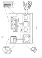
- FIG. 1 is an example of an environment 100 in which print instructions for printing an object based on modifications of at least one process parameter for at least a portion of a layer from a series of layers for printing by an extrusion-based 3D printer can be generated.
- the 3D model 104 may be provided (either from the client device 116 or through another computing device) for evaluation and generation of print instructions (e.g., by a slicer program included in the modelling system 102) that consider specifics of the geometry of the 3D model.
- the print instructions can include tailored (or modified) process parameters tailored to those specifics to yield a manufactured object that is improved in quality and/or is at least associated with lower chances of experiencing quality disruptions, at least due to the complexity of the object's geometry and related printing issues, as discussed in further detail below.
- the obtained properties can be determined to be related to possible or potential requirements for modification of the properties to improve print quality of an object.
- an identified feature for the 3D model 104 may be associated with a particular process parameter that can be modified to overcome expected quality defects due to the complexity or specificity of the object features or printing process parameters. For example, if the 3D model 104 is identified to include overhang regions based on an accessibility analysis performed at the feature generation module, the process parameter evaluator 124 may receive information for the overhang feature and may identify related process parameters that can be mapped to such a feature. The mapping of features to process parameters and respective modifications of the process parameters can be implemented at a parameter modifier 126 component.
- the logic of the process parameter evaluator 124 and the parameter modified 126 can be combined in a single component where rules can be defined for modifications to be applied over process parameter values and/or types based on particular geometric features that are identified.
- the logic for identifying, evaluating, and determining of modifications for process parameters based on geometric feature identification can be performed as described below in relation to FIG. 3B and 3C .
- the instruction generator 128 may generate multiple layers of the 3D model 104 and may rely on different parameter values (or types or an activation status of a process parameter) for the same parameter at different portions of one or more layers. The differences of the parameter values can be calculated and/or provided dynamically by the parameter modifier 126 to the instruction generator 128 during the path generation process or can be integrated into a path that has already been generated by an instruction generator that has not relied on logic for modifying the parameters (as the logic at the parameter modifier 126). Each of the slices may include data for multiple structures of the object represented by the respective slice.
- the instruction generator 128 may generate tool path data for each of the slices that indicates a path for a tool-head to create the structures represented by the slice.
- the instruction generator 128 may refer to different process parameters for different portions of each slice, where the process parameters used can depend on the modification of the process parameters to a subset of the slices based on the evaluated information for the geometric features of the 3D model 104.
- the print instruction generation module 108 may provide the data for each of the layers for printing of the object based on the 3D model 104, as determined based on the implemented process parameter modification logic, to the 3D extrusion printer 118 to cause the 3D printer 318 to generate the object (or a respective portion of the object). For instance, the print instruction generation module 108 may provide information for each of the series of layers defined for printing the object to the 3D printer 118. The print instruction generation module 108 may provide a first layer to the 3D extrusion printer 118. The 3D extrusion printer 118 may use the first layer to print the structures represented by the first layer.
- the modelling system 102 and the printing instruction generation module 108 can be examples of a system and a module implemented as computer programs on one or more computers in one or more locations, in which the systems, components, and techniques described in this document are implemented.
- the client device 116 may include personal computers, mobile communication devices, and other devices that can send and receive data over a network 120.
- the network 120 such as a local area network (LAN), wide area network (WAN), the Internet, or a combination thereof, connects the client device 116, modelling system 102, and the 3D extrusion printer 118.
- the modelling system 102 may use a single server computer or multiple server computers operating in conjunction with one another, including, for example, a set of remote computers deployed as a cloud computing service.
- the environment 100 does not include a separate printing instruction generation module and client device 116.
- the printing instruction generation module 108 may include the input/output interface code module 122 to receive the 3D model 104 from the modelling system 102 or to receive instructions to generate a 3D model, e.g., based on model generation services provided by the modelling system 102, and directly provide the model to the 3D printer 118 without interactions received from the client device 116.
- the printing instruction generation module 108 may provide the 3D model 104 directly to the 3D printer 118 without receiving the 3D model 104 from a separate device, e.g., the client device 116, for example, through the input/output interface code 122.
- the modelling system 102 can connect directly to the 3D extrusion printer 118 or can connect to the 3D extrusion printer 118 through any appropriate type of network, e.g., a LAN.
- the process 200 can be executed at a CAM or CAD environment, or another computer-aided engineering software environment.
- the process 200 can be executed to instruct a connected 3D printer (e.g., network or cable connected) to perform printing based on provided instructions that include path instructions adjusted to geometric specifics of the 3D model of the object to be printed to alleviate the chances of experiencing quality disruptions of the print result due to geometric specifics of the 3D model.
- a connected 3D printer e.g., network or cable connected
- the obtained process parameters may be provided from an external entity, where those parameters have been defined without taking into consideration the particular shape and/or other geometric features of the 3D model.
- complex 3D shapes for printing from particular material(s) at a extrusion-based 3D printer may be associated with expectations for experiencing quality defects that may result in a printed object that is uneven, cracked, or entangled, among other example quality disruptions.
- the process parameters can be default printing parameters that can be used by a selected 3D printer for the printing that can be generally applied to any object that can be requested for printing by the 3D printer.
- relying on the process parameters that are obtained at 202 for printing the object according to the 3D model can be associated with a probability for quality disruptions of the print result when printing an object that has a geometric feature that is predicted to experience a quality disruption.
- the obtained information for one or more geometric features includes information for at least one feature that may be associated with a prediction to experience a quality disruption.
- the obtained information identifies the object to be of a particular weight and to be of a certain shape that defines the object, such as a tall cylinder
- a certain shape that defines the object such as a tall cylinder
- a determination to modify one or more of the process parameters as obtained at 202 can be performed.
- the information regarding geometric features may include information for one or more of the geometric features as described in FIGS. 3A and 3B .
- an identified geometric feature e.g., an overhang region, an elliptical hole, a relatively heavy structure with a lot of contact with the printing platform, among other examples and as discussed in detail below
- process parameters e.g., an overhang region, an elliptical hole, a relatively heavy structure with a lot of contact with the printing platform, among other examples and as discussed in detail below
- Such identification of mapping between geometric features and process parameters, and implementing corresponding rules to modify process parameters to tailor them to the identified geometric features in the 3D model can be performed as described in further detail in relation to FIGS. 3A , 3B , and 3C .
- the process parameters can include settings of a print-head included in the 3D printer, settings of the 3D printer itself, or both, that will be used to create the object using the 3D model 104.
- settings for an extrusion-based 3D printer include a cooling fan speed, whether the printing platform bed of the printer is heated and the temperature setting thereof, the extruding temperature of the deposition chamber and/or print head of the printer, a diameter of an extruder nozzle in the print-head, print speed, bead diameter, and layer height, among other examples as discussed in further detail in relation to FIGS. 3A , 3B , and 3C .
- print instructions for the printing of the 3D object by the extrusion-based 3D printer in a series of multiple layers are generated.
- Modified process parameters are generated as part of the print instructions by modifying the obtained process parameters for a proper subset of layers based on the information regarding the one or more geometric features of the 3D model of the object.
- print instructions are generated for the printing of the 3D object by the extrusion-based 3D printer in the series of multiple layers.
- the print instructions can be generated by a path generation module 110 of FIG. 1 .
- the print instruction can define instructions for printing the object in layers where, for a portion of a layer, a modified process parameter different from the process parameter obtained at 202 can be used to address potential expectations of quality disruptions of the print result.
- modified process parameters are generated as part of generating the print instructions.
- the modified process parameters are generated by modifying at least one of the obtained process parameters for a proper subset of layers based on the information regarding the one or more geometric features of the 3D model of the object. In some implementations, only a portion of a single layer can be determined as a region (as a sub-region of a region associated with a geometric feature identified in the 3D model) where a modified parameter can be applied for the printing.
- an object is determined to have a large tall structure with a substantially small contact area with the printing platform, cracks on the sides may be expected.
- Such expectation for quality disruptions of the print result can be addressed by adjusting one or more process parameters.
- one or more parameters from the obtained parameters at 202 can be adapt (or modified) to the specifics of the tall structure where the adhesion in upper layers is lower.
- the material at higher layers is cooling faster due to the distance from a printing platform bed that is heated, which can result in undesired cracks for the print result.
- extruding temperature, fan direction, or speed of the fan can be adjusted to particular layers and locations to solve issues associated with such expected cracks.
- the modifications of one or more process parameters may be enforced only or substantially for an area of the 3D model that can overlap with one or more layers to be printed, for example, for a portion of the printing path at a layer, or for one or more full layers.
- a determination of a region(s) associated with a geometric feature can be provided. For example, for a tall thin structure, a determination of a set of subsequent layers of a determined height for the printed object can be provided.
- a tall thin structure can be a heavy object that has low contact area with the printing bed, which can be associated with expected issues during printing and quality disruptions at the end due to not balanced cooling of all layers while printing.
- issues of cooling may be addressed by adjusting printing process parameters, such as adjusting the printing platform temperature, adjusting the cooling fan speed, or other adjustments.
- a determination of relevant process parameters to be modified while printing an object, and at particular locations/portions of the object can be performed based on observation data analysis (e.g., based on historical data stored at a modelling system as discussed in relation to FIG. 1 ), or based on other prediction logic including machine learning techniques.
- the print instruction can be provided (204) to include the modified process parameters to operate the extrusion-based 3D printer to print the object.
- the print instructions may be provided for each layer determined for printing the 3D model and relying on corresponding process parameters as part of the print instructions.
- the provided process parameters include the modified process parameters that can be identified for each location within a path for a layer and/or for multiple layers (e.g., extruding temperature, cooling fan speed, etc.) and/or for applying between layers (e.g., print pause).
- the 3D printer e.g., the 3D printer 118 of FIG. 1
- the print instructions can be provided in portions, e.g., per layer, to the 3D printer.
- the 3D extrusion printer may use the instruction for the first layer to print the structures represented by the first layer.
- the print instructions can be provided through the CAD or CAM environment in a sequential manner, where the 3D extrusion printer can create corresponding structures of the object using the subsequent layer's instructions. For instance, the 3D extrusion printer may use each of the subsequent instructions for a subsequent layer to add another layer to the printed portion of the object until the object is completed.
- a 3D printer can print the object using a material that is defined, for example, plastic, metal, or another appropriate material compatible with the 3D printer where the print instructions can be provided.
- the process 200 can include additional operations or some of the operations can be divided into multiple operations.
- a CAD or CAM environment can be used to execute the operations 202, 204, and 206, where the modifications of the process parameters at 204 can be executed in a series of sub-operations, for example, based on processing logic of the obtained information for geometric features and process parameters as further described at operation 310 or FIG. 3A .
- FIG. 3A is a flow diagram of a process 300 for processing obtained information for geometric features of an object for printing by an extrusion-based 3D printer to define modifications for obtained process parameters for the printing.
- the process 300 can be executed at the environment 100 of FIG. 1 , and can be executed based on a provided instruction for printing an object based on a 3D model 304, such as the 3D model 104 of FIG. 1 .
- the process 300 can be executed at a path generation module that generates printing instructions for printing an object in a series of multiple layers (or slices).
- the process 300 can be executed at a CAM or CAD environment, or another computer-aided engineering software environment, or a modelling system such as the modelling system 102 of FIG. 1 .
- the process 300 can be executed to instruct a connected 3D printer (e.g., network or cable connected) to perform printing based on provided instructions that include path instructions adjusted to geometric specifics of the 3D model of the object to be printed to alleviate chances of experiencing quality disruptions of the print result due to geometric specifics of the 3D model.
- a connected 3D printer e.g., network or cable connected
- the process parameters 302 can be settings defined for printing an object of a given material at a 3D extrusion based printer.
- the process parameters as obtained can correspond to the process parameters obtained at 202 of FIG. 2 , and can include parameters such as extruding temperature, printing pause between layers, printing speed, printing platform temperature, cooling fan speed, infill density, infill print speed, infill overlap, top layer speed, support type for printing, or other.
- the information for the geometric features that is processed at 310 is information for geometric features such as overhang (positive and negative), elliptical holes, weight, ratio of an area of the model over a printing area, volume, contact area with the printing platform, outer wall, infill, horizontal height, and/or top portion.
- the geometric features can be identified based on an evaluator 306 that performs an evaluation of the 3D model 304 of an object.
- the evaluator 306 can be substantially similar to the feature identification module 106 of FIG. 1 .
- the evaluator can perform accessibility analysis to determine existing overhangs or undercut regions, or negative overhangs in the 3D model.
- the evaluator can perform measurements evaluation to determine weight, volume, height, contact areas of the model with the printing platform bed, ratio of the volume of the object to be printed to the volume of the printing space in the 3D printer, or other geometric features based on quantitative characteristics of the object.
- geometric features of the 3D model are evaluated, where the evaluated geometric features are such features that are predicted to experience quality disruptions, e.g., side cracks, skewed print result shape, elephant foot, others.
- a 3D model can have multiple geometric features where a subset of those features can be the geometric features that are evaluated since those are the features that are determined to be associated with predicted probability of experiencing quality disruption.
- the logic for the evaluation of features at 312 may be connected to an external or internal module that performs iterative evaluation of print results of objects from different 3D printers and identifies correspondence or relationship between a geometric feature of a 3D model and the likelihood of experiencing a quality disruption.
- the geometric features that are associated with expected quality disruptions are evaluated to determine whether a process parameter is to be adjusted.
- One geometric feature may be mapped to one or more process parameters that can be modified to address expected quality defects in the print result.
- the mapping between a geometric feature and a process parameter can be defined as described in connection with FIG. 3B .
- some or all of the process parameters 302 that are obtained at 310 can be adjustable, for example, based on user input and/or analysis of the geometric features of the 3D model.
- the modifications to one or more parameters are based on implemented logic to perform modifications to the process parameter values, or to turn on or off, or use, process configuration(s) (e.g., start cooling fan, use a support structure, etc.) that are defined according to identified one or more of geometric features 308.
- process configuration(s) e.g., start cooling fan, use a support structure, etc.
- one or more regions of the 3D model 304 are identified.
- the regions are correspondingly related to one or more features (from the geometric features 308) that are predicted to experience a quality disruption when printing based on the obtained process parameters.
- a modified process parameter per identified region is generated. For example, if an overhang feature is identified in the 3D model, a corresponding overhang region in the 3D model is identified.
- the overhang region as identified can be associated with one or more layers that are to be printed by the 3D extrusion printer.
- more than one region in the 3D model may be identified, where one region may be associated with one or more geometric features, and/or multiple regions may be located at different places around the 3D model and may be associated with modified parameters at the different regions, while the regions outside of the identified regions can apply process parameters as obtained from 302.
- the modified parameter(s) can be used for printing of a respective portion of one or more layers for printing the object (or a portion thereof) in a series of multiple layers by the extrusion-based 3D printer.
- a modified process parameter(s) based on a presence of a geometric feature in the 3D model can be generated for use within only a portion of the region (for example, within a predefined range of height of a tall structure object) and/or within only a portion of layers from the multiple layers generated for printing the object as a series of paths to create the object.
- the generation of the modified parameters can be performed based on evaluations, identifying of mappings between geometric features(s) and process parameter(s), and modification rules, as described below in relation to FIG. 3B .
- print instructions as generated are provided to be used for printing by relying on i) the obtained process parameters from 302 for regions of the 3D object outside of the identified regions as in 314 and ii) the modified parameters (as generated in 316) from the modified process parameters for the identified region(s) of the 3D model having the geometric feature (evaluated at 312).
- the print instructions can be dynamically provided during printing of the object by the extrusion-based 3D printer by supplying either the obtained process parameters (for regions of the 3D object outside of the identified regions within layers that are associated with modified process parameters) or the modified parameters for a respective identified region of the 3D model having the geometric feature that is predicted to experience the quality disruption.
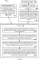
- FIG. 3B is a block diagram of a process to generate 317 modified process parameters for printing an object, the parameters being adjusted based on identifying one or more geometric features associated with expected quality disruptions.
- the generation of modified process parameter at 317 may be executed as part of operation 316 of the process 300 of FIG. 3 or as part of operation 204 of the process 200 of FIG. 2 .
- the generation 317 can be executed based on a provided instruction for printing an object based on a 3D model 304 of FIG. 3A , such as the 3D model 104 of FIG. 1 .
- the generated modified process parameters for identified one or more regions can be provided in sequences to a path generation module that generates printing instructions for printing an object in a series of multiple layers (or slices).
- mapping of a feature or a combination of features that comply with a certain criterion with one or more process parameters may be used when defining a modification for those mapped process parameters. For example, if a feature is complying with one criterion, a first process parameter may be modified for example to be increased, e.g., printing platform temperature can be increased for objects having a high contact area with the printing platform, while when the contact area is low, the printing platform temperature can be decreased.
- Such pause increase can be performed by modifying a printing pause process property of the 3D printer.
- the pause can be modified in a portion of layer that is at the vicinity of the overhang region within the layer that is to be printed to support a targeted effect only on the feature relevant portions within layers, or can be adjusted to be applied in between a subset of the layers for printing that overlap with the overhang region.
- the extruding temperature can be reduced by 5% and the print pause can be increased by 20%.
- Such example rule for modification of the extruding temperature parameter and the print pause parameter based on an identified overhang feature is provided at 350 of FIG. 3C .
- a negative overhang region can be identified as a geometric feature of a 3D model of an object to be printed.
- a negative overhang region can be a region that is concave and has a steeper portion that leads to bottom layers to form a concave gap of smaller width at each higher layer.
- printing problems may occur during the printing of the part when the surface area of the bottom layers of the material in contact with the printing bed are much larger than the overall surface area of a cross-section of the part.
- the bottom layers become hotter and the area of the bottom layers that surrounds one or more subsequent layers, where this area can be referred to as the surrounding area of the bottom layers (e.g., area that is defined within a pre-determined perimeter around the concave gap that is formed by the negative overhang region) can be small because of the smaller width of the overall surface area of the cross-section of the part.
- the overall surface area of the cross section of the part can include an area around the concave gap that is formed by the negative overhang region. In some instances, 3D printing performed with metal materials may be more likely to experience such "heat pool” issues compared to 3D printing with other materials such as plastic.
- a threshold width that can be considered as a small width that can be associated with experiencing quality disruptions, due to not balancing cooling of the bottom layer can be empirically determined.
- the area of the surface of the model of the part that is in contact with the printing bed (that is heated) can be calculated and surfaces of subsequent layers can be iteratively calculated to determine ratios between the width of the surface at the bottom and for the overall surface area. The determined ratios can be correlated with expected quality disruptions that can be identified when at least one of the ratios meet a particular threshold width difference criteria that is associated with a high probability of experiencing heat pool problems.
- the definition of the threshold can be empirically identified based on observations of historical data over executed printing jobs with varied part shapes and geometry considerations for the width of the part along its height to define different ratios between the surface area of the print in contact with the printing bed and the overall surface of a cross section of the respective part.
- the threshold can be determined to correspond to a probability threshold of experiencing quality disruptions (e.g., associated with a probability, of experiencing a quality disruption, that is above a threshold value such as 95% based on performed observations over a representative set of historical data).
- the printing bed temperature and the height of a current layer printed can be configured as parameters that are considered during the empirical determination of the threshold of experiencing quality disruptions due to the heat pool problem. For example, observations of printing of negative overhang regions can be made and evaluated to identify criteria for determining which negative overhang regions and what widths of the surrounding area of bottom layers is associated with quality disruptions for the end printed object at those negative overhang regions.
- one or more process parameters may be modified to support proper cooling of the regions associated with such "heat pools.” For example, when a negative overhang region is identified, the extruding temperature can be reduced or the print pause can be increase. In some more examples, both the extruding temperature and the print pause parameters can be modified to reduce the temperature and to provide more time for cooling that can help to solve the expected quality disruptions in the region of the negative overhang.
- the extruding temperature may be reduced by 5% and the print pause (either before a layer that includes portions of the negative overhang region or within a layer at a position at the layer that includes the negative overhang feature) can be increased by 20% (or added if no pause is already specified within the layer).
- an example rule for modification of the extruding temperature parameter and the print pause parameter based on an identified negative overhang feature is provided at 350 of FIG. 3C .
- the modifications of the process parameters can be enforced for one or more layers of the multiple layers for printing the object in series that include regions of the negative overhang region, or the process parameters can be enforced only within a layer (or layers) overlapped with the negative overhang but not in whole but only in portion of the layer.
- an elliptical hole can be a geometric feature of a 3D model of an object to be printed.
- an elliptical hole may be a hole that can have a substantially (or fully) circular shape or partially elliptical shape in the 3D model.
- the hole can have an elliptical shape and can be formed at a cross section of the 3D object, where the plane of the cross section can be parallel to the print direction (thus, a "hole" includes empty space having spherical shapes that are entirely internal to the printed object).
- the 3D model can include a hole that can be seen as in the examples 370 when looked at a cross-section of the object.
- the print result may have an elongated elliptical hole instead of a more circular one.
- changing the printing parameters in the region of the hole can avoid the elongation or other shape distortion of the hole to provide a print result that is substantially similar to the design of the hole as in the 3D model (e.g., defined in a CAD or CAM environment).
- the extruding temperature can be reduced by 5%
- the print speed can be reduced by 10%
- the print pause can be increased by 20%.
- only a subset of these parameters may be changed, and different combinations of the proposed modifications can be applied.
- Such an example of a rule for modification of the extruding temperature parameter, the print speed, and the print pause parameter based on an identified hole feature is provided at 355 of FIG. 3C .
- Object requires one or more support structures
- a support structure can facilitate the printing of portions of an object by providing a support layer for overhanging structures or bridge structures defined when slicing the 3D model into a series of layers for printing.
- a support may fall apart and leave at least a portion of the printed object unsupported. Based on such falling apart of a support structure at a particular location of the object, quality disruptions at that location can be noticeable. For example, since the support had fallen out, the print can still be extruded at that part where the support was expected but it can have an uneven or cracked appearance, or can look stringy.
- support structure can be defined and multiple options for selecting a type of a support structure may be provided.
- a default support type structure may be provided as part of the printing process parameters to be used during printing of the obj ect.
- a modification of the support structure part may be made to select a different support type that would be associated with higher probability of not falling apart (e.g., based on observations and evaluation of historical data for use of different support types for differently sized overhang regions) and successfully supporting the printing of overhang regions.
- the extruding temperature, the speed and the feed during the printing can be modified (or tailored) to support improved rigidity and adhesion of the printed part to the selected support.
- the print instruction can include instructions to use a lines or zig zag support structure type.
- the contact area of the overhang region with the printing platform is determined to be below the threshold size, an instruction to use a grid or triangle support structure type for the support structure can be provided.
- the obtained information for one or more geometric features may include information for the volume of the model and a contact area of the model with the printing platform.
- a weight of the model can be determined.
- a ratio of the area of the model to the platform area can be determined.
- the weight of the object as well as the contact area ratio can be evaluated to determine whether the object can be categorized as heavy (e.g., based on a predefined criteria or a threshold value for comparison with the weight of the object) and whether the object has low contact area with the printing platform.
- the ratio as determined can be compared to a threshold ratio to determine whether the contact is low or high. For example, if the contact area is 20% (or less) of the printing platform area, the object can be categorized to have a low contact area.
- a 3D model can be such that the base of the printed object slightly bulges outwards (an effect otherwise known as "elephant foot") when the weight of the objects during printing presses down the lower layers before they have properly cooled into a solid.
- an effect otherwise known as "elephant foot” may arise when the printer has a heated printing platform bed.
- the quality issue that results in the bulging outward of edges of an object is also known as an "elephant's foot.”
- the base layers of the model may be provided with time to sufficiently cool during printing so that they can serve as support for the structure built on top such that they may not change due to the heavy weight of the higher portions of the object.
- the print result may risk having its base layers warping.
- the print instructions for the object generated layer by layer can include modified parameters for all layers or portions of layers of the heavy object.
- the modified parameters can be tailored to help balance the cooling and/or heating during the printing to avoid "elephant foot," without risking the base layers to warp.
- the modification of the parameters can be provided for one or more layers that are a very first set of layers of the object printed by the extrusion-based 3D printer. For example, the number of layers that can be affected by a modification can be determined to overlap a certain height of the object provided as a threshold value to the process modifier.
- some of the process parameters associated with the temperature of the layers during printing can be modified.
- the modified process parameters can include at least one of an extruder temperature, a printing platform (or printing bed) temperature, and settings of the cooling fan (e.g., start the cooling fan at a lower or higher height of the print and/or increase or decrease the speed of the cooling fan to support faster cooling).
- the extruding temperature and/or the printing platform temperature can be lowered to support faster cooling of lower layers and thus to avoid "elephant foot" appearing in the print.
- the lowering of the temperature can be such that allows for lower layers to cool to a predefined level that would not be associated with higher probability of resulting in base layers warping.
- the extruding temperature and/or the printing platform temperature can be lowered for at least a portion of the printing process associated with regions of the print at the lowest part of the object that are in proximity to the printing platform.
- these parameters can be tailored to the geometry of the part and can be adjusted, in combination or separately, to allow the lower parts of a heavy object that has low contact area with the printing platform to sufficiently cool down prior extruding further subsequent layers that are hot and rely on the lower part as a support structure. Such modifications may lower the risk of experiencing "elephant foot” and support avoidance of quality disruptions at the end print result.
- cooling fan start point e.g., height of the print when the cooling fan is started
- speed e.g., the speed of the cooling fan configured for the whole printing process or at least for lower portions of the print
- the settings of the cooling fan can be modified to reduce the risk of experiencing "elephant foot" issues at the end print result by providing cooling at lower height of the print.
- the cooling fan can be started at a lower height of the print to support faster cooling at the lower layers thus to avoid the appearance of "elephant foot".
- the cooling fan may have default print settings to be started at a particular height of the print, and those settings can be modified by reducing the default height to a new lower height that is, for example, 50% lower than the default one.
- the cooling fan speed can be adjusted by configuring the cooling fan to start and provide cooling due to an increase in the fan speed, for example, by 50%.
- the cooling fan may be configured to work during a portion or the whole of the printing process as a default print configuration that did not take into account geometric specifics of the printed object.
- the cooling fan speed can be modified by setting the cooling fan speed to be higher (e.g., 50% higher) than the set default speed. Thus would allow the fan to cool faster at lower layers and thus to support the avoidance of the appearance of "elephant foot.”
- the cooling fan speed may be kept steady as modified and without intermediate adjustments during the printing process based on considerations of the geometry of the part and the printing configuration at the printer.
- the modifications for the cooling fan either the fan speed or the start height for the cooling fan, can be applied for the whole or a portion of the printing process.
- the printing platform temperature can be reduced, e.g., by 10%, and the cooling fan can be configured to be started at a lower height in the printing process compared to a default higher height configured for the cooling fan in obtained process parameters.
- the cooling fan speed can be increased, e.g., by 50%, from a default fan speed for at least the lower portions of the print associated with lower height(s).
- the cooling fan can be configured by default to start at height 2 and when it is determined that the object is heavy and has low contact area with the printing platform, that height 2 can be modified and defined to be height 1 (lower than height 2), which for example is 50% of the height 2.
- the modification of the triggering of the cooling fan start point can support the cooling down of the extruded filament faster as it will be initiated earlier in the printing process.
- the filament that is extruded in a lower layer during printing of the model can be cooled faster since it now has the fan blowing turned on, which would not have been the case if the fan start height was not adjusted to the lower height level.
- Such an example rule for modification of the extruding temperature, the printing platform temperature, and/or the cooling fan settings (start height and/or speed) based on an identified heavy object with low contact area with the printing platform is provided at 360 of FIG. 3D .
- the base of the printed object can bend upwards and it may result in base that is no longer level with the printing platform surface. Having such warping at the bottom of a printed object can also result in horizontal cracks in upper parts and cause a print object to look unstuck from the print bed. Similar to "elephant foot”, tailored balancing between cooling and heating during printing can be applied to avoid such warping and crack quality disruptions. Such predicted quality disruptions can be avoided by adjusting some of the process parameters.
- the printing platform temperature can be increased and the cooling provided by the cooling fan of the 3D printer may be decreased.
- the printing platform temperature can be increased by 10%
- the cooling fan speed at the 3D printer can be decreased by 50%
- the cooling fan start height can be defined to be 50% higher than a default height defined for starting the cooling fan in the default printing parameters.
- the speed of the cooling fan can be adjusted based on evaluating whether there have been already some modifications to adjust the speed that may indicate that further changes to the speed (e.g., further decrease) may not be necessary or may not be desirable.
- a slicer program may be configured with settings for the cooling fan (speed and/or start height) and/or modifications to the cooling fan settings based on predefined rules or criteria for modification to address risks of warping.
- the cooling fan can be set to switch to full power at a higher height of the print while not being used (or substantially not used) at lower portions of the print to allow base layers that have already been printed to have more time to cool naturally without cooling due to the fan.
- the slicer program can be configured with settings to modify the cooling fan speed by reducing the speed to reduce the cooling effect from the fan and to allow the base layers to have more time to cool naturally.
- Such example rule for modification of the printing platform temperature and the cooling fan speed based on an identified high contact area with the printing platform is provided at 365 of FIG. 3D .
- a path generator can define an internal structure of a 3D model of an object to be printed by an extrusion based 3D printer in a series of printing paths.
- the internal structure is an infill that can have different density.
- the infill can provide support for upper and/or top layers. Determining the density that is to be applied for the infill settings can depend on the strength that is required to be provided by the print result, on support requirements for upper layers, or on quality criteria, among other. Generally, there are different patterns that can be set for the infill. Also, there are different patterns of the infill that can be applied to provide a particular infill density.
- the instructions to print an object include process parameters such as speed and density of printing the paths in the infill structures.
- the speed at which the infill structures are printed can affect the quality of the print result for the object. If the speed and/or density of the printing is not properly set, the infill structure may look messy or incomplete.
- the volume of the object can be a geometric feature obtained for the model and compared to a threshold value to determine whether such object is expected to experience quality disruptions.
- the volume size of objects that experience quality issues can be empirically determined and used to define rules for modifying process parameters.
- the volume of an object can be compared with a threshold value defining an expect volume size that if exceeded can affect the quality. When the volume increases the threshold, the object can be considered to be of sufficiently high volume that can lead to experiencing quality disruptions when printing the infill structure.
- Such predicted quality disruptions can be avoided by adjusting some of the process parameters, such as infill density and infill print speed.
- the printing infill density can be set to not less than 20% and the infill print speed can be decreased by 10%.
- Some 3D models of objects have outer walls and infill structures. Different infill settings can be defined for the infill density.
- a path generation program (or a slicer program) can define for each sliced layer one or more toolpaths defining the infill of the object and one or more toolpaths defining the perimeter area of the outer walls.
- the infill toolpath at each layer can reach an outer toolpath covering the perimeter of the 3D model where the infill meets the outer walls.
- the infill toolpath can have different overlappings with the inner edge of the perimeter of the outer walls of the 3D model.
- an object can be a cube having a round cylindrical hole that crosses the cube structure.
- such objects have outer walls within the object that surround holes inside the object and the object has infill structures up to the outer wall.
- a quality disruption that may occur can be associated with poor quality results of the print at the top layer. For example, a slight gap between the infill and the outer perimeter walls can be noticed. In some cases, such gaps may be caused by the filament used for the infill and outer wall(s) to not quite meet and provide a poor bonding at the adjoining area between the infill and the outer wall. In some instances, the overlap between the infill and the outer wall may not be sufficient to prevent the infill and the outer wall from failing to meet and bond.
- such issue may be more prevalent when the object is printed from particular materials. Those materials can be poor in spreading out due to carbon fibers that make up part of their structure. In some implementations, when using an advanced material for printing, tailoring hot end temperature may avoid the appearance of such quality disruptions.
- process parameters can be modified for at least some layers of multiple layers defined for printing the object.
- an infill pattern type and infill density, and/or the print speed parameters can be modified so that the infill overlap gets adjusted and the appearance of such gap quality disruptions between the infill paths and the outer perimeter paths, for example, at the top set of layers, is reduced or completely diminished.
- the infill overlap can be set to not less than 30% and below 50%, and the top layer speed of the print head can be reduced by 20 %.
- the infill structure when layers of the infill structure are sequentially printed, they need to cool down quickly to avoid falling of newly printed material at a subsequent higher layer (and eventually the top layer) into the holes defined in the infill structure.
- the size of the holes within the infill structure depends on the defined infill density and pattern.
- FIG. 3C is a block diagram of rules for modifications of process parameters that are applied during printing of an object by a 3D extrusion printer to tailor the process parameters to the geometric features identified in the object at different portions of a generated print path.
- the modification of the process parameters can be generated in parallel or substantially in parallel with the printing process.
- the modifications of the process parameters can be generated during slicing of the model, for example, at a slicer program included in a modelling system such as the modeling system 102 of FIG. 1 , to prepare the model of the part for printing in accordance with implementations of the present disclosure.
- an example modification rule for modifying an extruding temperature parameter and a print pause parameter based on an identified overhang or a negative overhang geometric feature is provided.
- the rule 350 also identified the configuration of the application of the modification of the process parameters - either within a layer, before and after layers including portions of regions of the identified overhang geometric features.
- an example rule for modification of the extruding temperature parameter, the print speed, and the print pause parameter based on an identified hole feature is provided.
- the rule 355 identifies a configuration of the application of the modification of the process parameters at one or more subset layer from the layer.
- the configuration of the application of the modified parameters can be either for the layers as a whole or the modification of the change in the parameters can be activated within a layer just prior and after a portion of the layer overlaying the overhang feature.
- FIG. 3D is a block diagram of rules for modifications of process parameters that are applied during printing of an object expected to experience elephant foot issues or warping at the bottom layers when printed by a 3D extrusion printer.
- the modification of the process parameters can be generated in parallel or substantially in parallel with the printing process.
- the generations of the modifications can be performed at stages, where each stage may be executed in different manner where some stages may include modifications that are executed during printing, and some other stages may include defining the modifications for a set of layers before sending instructions to print.
- the rules 360 and 365 define corresponding parameters that are to be modified for objects which are heavy and with low or high contact area with the printing platform to alleviate the chance of experiencing elephant foot issues and warping issues at the bottom layers when printing objects with 3D printers having heated printing platform bed.
- a set of options for modification of corresponding to different combinations of mapped process parameters to a geometric feature included in the 3D model of the object can be provided.
- one or more options for modification of combination of the parameters including the extruding temperature, the print speed, and/or the print pause can be provided with a corresponding modified value.
- a selection of a particular modification to a particular set of one or more parameters can be defined. The selection of an option can be based on a predetermined selection rule that can be defined based on a printer type, an identifier of a user, an account (e.g., customer account, subscription account, etc.) associated with the user request.
- the selection can be a user selection, where the options can be provided at a user interface (e.g., a graphical user interface) of a print instruction module (e.g., such as the path generation module 110 of the printing instruction generation module 108 of FG. 1) where print instructions are generated.
- a user interface e.g., a graphical user interface
- a print instruction module e.g., such as the path generation module 110 of the printing instruction generation module 108 of FG. 1
- Embodiments of the subject matter and the functional operations described in this specification can be implemented in digital electronic circuitry, in tangibly-embodied computer software or firmware, in computer hardware, including the structures disclosed in this specification and their structural equivalents, or in combinations of one or more of them.
- Embodiments of the subject matter described in this specification can be implemented as one or more computer programs, i.e., one or more modules of computer program instructions encoded on a tangible non-transitory program carrier for execution by, or to control the operation of, data processing apparatus.
- the program instructions can be encoded on an artificially-generated propagated signal, e.g., a machine-generated electrical, optical, or electromagnetic signal, that is generated to encode information for transmission to suitable receiver apparatus for execution by a data processing apparatus.
- the computer storage medium can be a machine-readable storage device, a machine-readable storage substrate, a random or serial access memory device, or a combination of one or more of them.
- data processing apparatus refers to data processing hardware and encompasses all kinds of apparatus, devices, and machines for processing data, including by way of example a programmable processor, a computer, or multiple processors or computers.
- the apparatus can also be or further include special purpose logic circuitry, e.g., an FPGA (field programmable gate array) or an ASIC (application-specific integrated circuit).
- the apparatus can optionally include, in addition to hardware, code that creates an execution environment for computer programs, e.g., code that constitutes processor firmware, a protocol stack, a database management system, an operating system, or a combination of one or more of them.
- a computer program which may also be referred to or described as a program, software, a software application, a module, a software module, a script, or code, can be written in any form of programming language, including compiled or interpreted languages, or declarative or procedural languages, and it can be deployed in any form, including as a stand-alone program or as a module, component, subroutine, or other unit suitable for use in a computing environment.
- a computer program may, but need not, correspond to a file in a file system.
- a program can be stored in a portion of a file that holds other programs or data, e.g., one or more scripts stored in a markup language document, in a single file dedicated to the program in question, or in multiple coordinated files, e.g., files that store one or more modules, sub-programs, or portions of code.
- a computer program can be deployed to be executed on one computer or on multiple computers that are located at one site or distributed across multiple sites and interconnected by a communication network.
- the processes and logic flows described in this specification can be performed by one or more programmable computers executing one or more computer programs to perform functions by operating on input data and generating output.
- the processes and logic flows can also be performed by, and apparatus can also be implemented as, special purpose logic circuitry, e.g., an FPGA (field programmable gate array) or an ASIC (application-specific integrated circuit).
- special purpose logic circuitry e.g., an FPGA (field programmable gate array) or an ASIC (application-specific integrated circuit).
- Computers suitable for the execution of a computer program include, by way of example, general or special purpose microprocessors or both, or any other kind of central processing unit.
- a central processing unit will receive instructions and data from a read-only memory or a random access memory or both.
- the essential elements of a computer are a central processing unit for performing or executing instructions and one or more memory devices for storing instructions and data.
- a computer will also include, or be operatively coupled to receive data from or transfer data to, or both, one or more mass storage devices for storing data, e.g., magnetic, magneto-optical disks, or optical disks.
- mass storage devices for storing data, e.g., magnetic, magneto-optical disks, or optical disks.
- a computer need not have such devices.
- a computer can be embedded in another device, e.g., a mobile telephone, a personal digital assistant (PDA), a mobile audio or video player, a game console, a Global Positioning System (GPS) receiver, or a portable storage device, e.g., a universal serial bus (USB) flash drive, to name just a few.
- PDA personal digital assistant
- GPS Global Positioning System
- USB universal serial bus
- Computer-readable media suitable for storing computer program instructions and data include all forms of non-volatile memory, media and memory devices, including by way of example semiconductor memory devices, e.g., EPROM, EEPROM, and flash memory devices; magnetic disks, e.g., internal hard disks or removable disks; magneto-optical disks; and CD-ROM and DVD-ROM disks.
- semiconductor memory devices e.g., EPROM, EEPROM, and flash memory devices
- magnetic disks e.g., internal hard disks or removable disks
- magneto-optical disks e.g., CD-ROM and DVD-ROM disks.
- the processor and the memory can be supplemented by, or incorporated in, special purpose logic circuitry.
- a computer having a display device, e.g., LCD (liquid crystal display), OLED (organic light emitting diode) or other monitor, for displaying information to the user and a keyboard and a pointing device, e.g., a mouse or a trackball, by which the user can provide input to the computer.
- a display device e.g., LCD (liquid crystal display), OLED (organic light emitting diode) or other monitor
- a keyboard and a pointing device e.g., a mouse or a trackball
- Other kinds of devices can be used to provide for interaction with a user as well; for example, feedback provided to the user can be any form of sensory feedback, e.g., visual feedback, auditory feedback, or tactile feedback; and input from the user can be received in any form, including acoustic, speech, or tactile input.
- a computer can interact with a user by sending documents to and receiving documents from a device that is used by the user; for example, by sending web pages to
- Embodiments of the subject matter described in this specification can be implemented in a computing system that includes a back-end component, e.g., as a data server, or that includes a middleware component, e.g., an application server, or that includes a front-end component, e.g., a client computer having a graphical user interface or a Web browser through which a user can interact with an implementation of the subject matter described in this specification, or any combination of one or more such back-end, middleware, or front-end components.
- the components of the system can be interconnected by any form or medium of digital data communication, e.g., a communication network. Examples of communication networks include a local area network (LAN) and a wide area network (WAN), e.g., the Internet.
- LAN local area network
- WAN wide area network
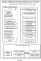
- FIG. 4 shows a schematic diagram of a computer system 400.
- the system 400 can be used for the operations described in association with any of the computer-implemented methods described previously, according to some implementations.
- the system 400 includes a processor 410, a memory 420, a storage device 430, and an input/output device 440. Each of the components 410, 420, 430, and 440 are interconnected using a system bus 450.
- the processor 410 is capable of processing instructions for execution within the system 400. In some implementations, the processor 410 is a single-threaded processor. In other implementations, the processor 410 is a multi-threaded processor.
- the processor 410 is capable of processing instructions stored in the memory 420 or on the storage device 430 to display graphical information for a user interface on the input/output device 440.
- the memory 420 stores information within the system 400.
- the memory 420 is a non-transitory computer-readable medium.
- the memory 420 is a volatile memory unit.
- the memory 420 is a non-volatile memory unit.
- the storage device 430 is capable of providing mass storage for the system 400.
- the storage device 430 is a non-transitory computer-readable medium.
- the storage device 430 may be a floppy disk device, a hard disk device, an optical disk device, a tape device, or a solid state memory device.
- the input/output device 440 provides input/output operations for the system 400.
- the input/output device 440 includes a keyboard and/or pointing device.
- the input/output device 440 includes a display unit for displaying graphical user interfaces.
Landscapes
- Engineering & Computer Science (AREA)
- Chemical & Material Sciences (AREA)
- Materials Engineering (AREA)
- Manufacturing & Machinery (AREA)
- Physics & Mathematics (AREA)
- Mechanical Engineering (AREA)
- Optics & Photonics (AREA)
- Life Sciences & Earth Sciences (AREA)
- Sustainable Development (AREA)
- Automation & Control Theory (AREA)
Applications Claiming Priority (2)
| Application Number | Priority Date | Filing Date | Title |
|---|---|---|---|
| US17/990,521 US12491684B2 (en) | 2022-11-18 | 2022-11-18 | Process-aware additive computer aided manufacturing |
| EP23209776.6A EP4371735A3 (fr) | 2022-11-18 | 2023-11-14 | Fabrication assistée par ordinateur additive sensible au processus |
Related Parent Applications (1)
| Application Number | Title | Priority Date | Filing Date |
|---|---|---|---|
| EP23209776.6A Division EP4371735A3 (fr) | 2022-11-18 | 2023-11-14 | Fabrication assistée par ordinateur additive sensible au processus |
Publications (2)
| Publication Number | Publication Date |
|---|---|
| EP4523819A2 true EP4523819A2 (fr) | 2025-03-19 |
| EP4523819A3 EP4523819A3 (fr) | 2026-01-07 |
Family
ID=88833526
Family Applications (3)
| Application Number | Title | Priority Date | Filing Date |
|---|---|---|---|
| EP25155375.6A Pending EP4523818A3 (fr) | 2022-11-18 | 2023-11-14 | Fabrication assistée par ordinateur additive sensible au processus |
| EP25155376.4A Pending EP4523819A3 (fr) | 2022-11-18 | 2023-11-14 | Fabrication assistée par ordinateur additive sensible au processus |
| EP23209776.6A Pending EP4371735A3 (fr) | 2022-11-18 | 2023-11-14 | Fabrication assistée par ordinateur additive sensible au processus |
Family Applications Before (1)
| Application Number | Title | Priority Date | Filing Date |
|---|---|---|---|
| EP25155375.6A Pending EP4523818A3 (fr) | 2022-11-18 | 2023-11-14 | Fabrication assistée par ordinateur additive sensible au processus |
Family Applications After (1)
| Application Number | Title | Priority Date | Filing Date |
|---|---|---|---|
| EP23209776.6A Pending EP4371735A3 (fr) | 2022-11-18 | 2023-11-14 | Fabrication assistée par ordinateur additive sensible au processus |
Country Status (3)
| Country | Link |
|---|---|
| US (1) | US12491684B2 (fr) |
| EP (3) | EP4523818A3 (fr) |
| CN (1) | CN118056668A (fr) |
Families Citing this family (1)
| Publication number | Priority date | Publication date | Assignee | Title |
|---|---|---|---|---|
| CN119806445B (zh) * | 2024-12-30 | 2026-02-06 | 广州小猴云印软件有限公司 | 应用于云打印的实时修改控制方法、装置、设备及介质 |
Family Cites Families (11)
| Publication number | Priority date | Publication date | Assignee | Title |
|---|---|---|---|---|
| US9744727B2 (en) * | 2014-04-02 | 2017-08-29 | Autodesk, Inc. | Electro-mechanical 3D printing design system |
| US9895845B2 (en) | 2015-02-16 | 2018-02-20 | Arevo Inc. | Method and a system to optimize printing parameters in additive manufacturing process |
| US10639878B2 (en) | 2017-02-15 | 2020-05-05 | Autodesk, Inc. | Three-dimensional printing |
| US10996652B2 (en) * | 2017-04-21 | 2021-05-04 | Desktop Metal, Inc. | Adaptive 3D printing |
| US11130292B2 (en) | 2017-05-08 | 2021-09-28 | Autodesk, Inc. | Estimating physical property of 3D printed parts |
| US11084222B2 (en) | 2017-06-30 | 2021-08-10 | Autodesk, Inc. | Systems and methods for determining dynamic forces in a liquefier system in additive manufacturing |
| WO2019183240A1 (fr) * | 2018-03-21 | 2019-09-26 | Essentium Inc. | Système d'impression 3d par extrusion à grande vitesse |
| EP3797026A4 (fr) * | 2018-05-22 | 2022-03-02 | Mantle Inc. | Procédé et système de génération de trajectoire d'outil automatisée |
| EP4153398A1 (fr) | 2020-05-21 | 2023-03-29 | Chromatic 3D Materials Inc. | Procédé d'impression tridimensionnelle de pièces avec surplomb |
| CN115867432A (zh) * | 2020-07-01 | 2023-03-28 | 惠普发展公司,有限责任合伙企业 | 确定从选择的构建材料打印3d对象预期会导致缺陷 |
| US12326710B2 (en) * | 2021-08-10 | 2025-06-10 | International Business Machines Corporation | Creating string-based force component from different directions during overhang three-dimensional printing |
-
2022
- 2022-11-18 US US17/990,521 patent/US12491684B2/en active Active
-
2023
- 2023-11-14 EP EP25155375.6A patent/EP4523818A3/fr active Pending
- 2023-11-14 EP EP25155376.4A patent/EP4523819A3/fr active Pending
- 2023-11-14 EP EP23209776.6A patent/EP4371735A3/fr active Pending
- 2023-11-17 CN CN202311533937.0A patent/CN118056668A/zh active Pending
Also Published As
| Publication number | Publication date |
|---|---|
| EP4371735A2 (fr) | 2024-05-22 |
| EP4523818A3 (fr) | 2025-12-10 |
| US20240165883A1 (en) | 2024-05-23 |
| US12491684B2 (en) | 2025-12-09 |
| EP4523818A2 (fr) | 2025-03-19 |
| EP4371735A3 (fr) | 2024-07-17 |
| CN118056668A (zh) | 2024-05-21 |
| EP4523819A3 (fr) | 2026-01-07 |
Similar Documents
| Publication | Publication Date | Title |
|---|---|---|
| US12059845B2 (en) | Interactive slicing methods and systems for generating toolpaths for printing three-dimensional objects | |
| US11513495B2 (en) | Building and attaching support structures for 3D printing | |
| TWI594099B (zh) | 三維物件產生技術 | |
| US10328686B2 (en) | Determining print-time for generation of 3D objects based on 3D printing parameters | |
| CN111684449B (zh) | 利用热和应变建模生成增材制造扫描路径的方法和设备 | |
| US10775769B2 (en) | Information processing apparatus, control method, and storage medium | |
| US20170248937A1 (en) | System and methods for three-dimensional printing | |
| EP4523819A2 (fr) | Fabrication assistée par ordinateur additive sensible au processus | |
| Barclift et al. | CAD-integrated cost estimation and build orientation optimization to support design for metal additive manufacturing | |
| CN109072600B (zh) | 3d打印 | |
| US20150251358A1 (en) | Three dimensional printing apparatus and method for controlling printing head thereof | |
| CN113536526A (zh) | 基于构建件的位置和方向仿真优化表面质量的系统和方法 | |
| JP2020001302A (ja) | 造形予測システム、造形予測表示システム、情報処理装置およびプログラム | |
| US20240027996A1 (en) | Systems and methods for administering a 3d-printing-based manufacturing process | |
| EP3616885A1 (fr) | Procédé d'impression tridimensionnelle et imprimante tridimensionnelle | |
| US10434758B2 (en) | Three-dimensional printing method and three-dimensional printing apparatus | |
| CN112004654A (zh) | 打包三维构建床 | |
| US20230280717A1 (en) | Heat-aware toolpath generation for 3d printing of physical parts | |
| Tziantopoulos et al. | Additive manufacturing: a decision support system for spare parts inventory management | |
| US20240025124A1 (en) | Techniques to determine improved print configurations in hybrid manufacturing | |
| TWI680859B (zh) | 立體列印方法與立體列印裝置 | |
| CN116890459A (zh) | 用于生成输出机器控制数据的计算机实现的方法 |
Legal Events
| Date | Code | Title | Description |
|---|---|---|---|
| PUAI | Public reference made under article 153(3) epc to a published international application that has entered the european phase |
Free format text: ORIGINAL CODE: 0009012 |
|
| STAA | Information on the status of an ep patent application or granted ep patent |
Free format text: STATUS: REQUEST FOR EXAMINATION WAS MADE |
|
| 17P | Request for examination filed |
Effective date: 20250131 |
|
| AC | Divisional application: reference to earlier application |
Ref document number: 4371735 Country of ref document: EP Kind code of ref document: P |
|
| AK | Designated contracting states |
Kind code of ref document: A2 Designated state(s): AL AT BE BG CH CY CZ DE DK EE ES FI FR GB GR HR HU IE IS IT LI LT LU LV MC ME MK MT NL NO PL PT RO RS SE SI SK SM TR |
|
| REG | Reference to a national code |
Ref country code: DE Ref legal event code: R079 Free format text: PREVIOUS MAIN CLASS: B22F0010850000 Ipc: B29C0064118000 |
|
| RIC1 | Information provided on ipc code assigned before grant |
Ipc: B29C 64/118 20170101AFI20250814BHEP Ipc: B29C 64/393 20170101ALI20250814BHEP Ipc: B33Y 10/00 20150101ALI20250814BHEP Ipc: B33Y 50/02 20150101ALI20250814BHEP Ipc: B22F 10/18 20210101ALI20250814BHEP Ipc: B22F 10/85 20210101ALI20250814BHEP Ipc: B22F 10/38 20210101ALI20250814BHEP |
|
| PUAL | Search report despatched |
Free format text: ORIGINAL CODE: 0009013 |
|
| AK | Designated contracting states |
Kind code of ref document: A3 Designated state(s): AL AT BE BG CH CY CZ DE DK EE ES FI FR GB GR HR HU IE IS IT LI LT LU LV MC ME MK MT NL NO PL PT RO RS SE SI SK SM TR |
|
| RIC1 | Information provided on ipc code assigned before grant |
Ipc: B29C 64/118 20170101AFI20251203BHEP Ipc: B29C 64/393 20170101ALI20251203BHEP Ipc: B33Y 10/00 20150101ALI20251203BHEP Ipc: B33Y 50/02 20150101ALI20251203BHEP Ipc: B22F 10/18 20210101ALI20251203BHEP Ipc: B22F 10/85 20210101ALI20251203BHEP Ipc: B22F 10/38 20210101ALI20251203BHEP |