EP4521742A2 - Bilddecodierungsvorrichtung, bilddecodierungsverfahren und programm - Google Patents
Bilddecodierungsvorrichtung, bilddecodierungsverfahren und programm Download PDFInfo
- Publication number
- EP4521742A2 EP4521742A2 EP25154459.9A EP25154459A EP4521742A2 EP 4521742 A2 EP4521742 A2 EP 4521742A2 EP 25154459 A EP25154459 A EP 25154459A EP 4521742 A2 EP4521742 A2 EP 4521742A2
- Authority
- EP
- European Patent Office
- Prior art keywords
- value
- decoded signal
- threshold value
- filtering process
- filter
- Prior art date
- Legal status (The legal status is an assumption and is not a legal conclusion. Google has not performed a legal analysis and makes no representation as to the accuracy of the status listed.)
- Pending
Links
Images






Classifications
-
- H—ELECTRICITY
- H04—ELECTRIC COMMUNICATION TECHNIQUE
- H04N—PICTORIAL COMMUNICATION, e.g. TELEVISION
- H04N19/00—Methods or arrangements for coding, decoding, compressing or decompressing digital video signals
- H04N19/10—Methods or arrangements for coding, decoding, compressing or decompressing digital video signals using adaptive coding
- H04N19/102—Methods or arrangements for coding, decoding, compressing or decompressing digital video signals using adaptive coding characterised by the element, parameter or selection affected or controlled by the adaptive coding
- H04N19/117—Filters, e.g. for pre-processing or post-processing
-
- H—ELECTRICITY
- H04—ELECTRIC COMMUNICATION TECHNIQUE
- H04N—PICTORIAL COMMUNICATION, e.g. TELEVISION
- H04N19/00—Methods or arrangements for coding, decoding, compressing or decompressing digital video signals
- H04N19/10—Methods or arrangements for coding, decoding, compressing or decompressing digital video signals using adaptive coding
- H04N19/134—Methods or arrangements for coding, decoding, compressing or decompressing digital video signals using adaptive coding characterised by the element, parameter or criterion affecting or controlling the adaptive coding
-
- H—ELECTRICITY
- H04—ELECTRIC COMMUNICATION TECHNIQUE
- H04N—PICTORIAL COMMUNICATION, e.g. TELEVISION
- H04N19/00—Methods or arrangements for coding, decoding, compressing or decompressing digital video signals
- H04N19/10—Methods or arrangements for coding, decoding, compressing or decompressing digital video signals using adaptive coding
- H04N19/134—Methods or arrangements for coding, decoding, compressing or decompressing digital video signals using adaptive coding characterised by the element, parameter or criterion affecting or controlling the adaptive coding
- H04N19/136—Incoming video signal characteristics or properties
- H04N19/14—Coding unit complexity, e.g. amount of activity or edge presence estimation
-
- H—ELECTRICITY
- H04—ELECTRIC COMMUNICATION TECHNIQUE
- H04N—PICTORIAL COMMUNICATION, e.g. TELEVISION
- H04N19/00—Methods or arrangements for coding, decoding, compressing or decompressing digital video signals
- H04N19/10—Methods or arrangements for coding, decoding, compressing or decompressing digital video signals using adaptive coding
- H04N19/169—Methods or arrangements for coding, decoding, compressing or decompressing digital video signals using adaptive coding characterised by the coding unit, i.e. the structural portion or semantic portion of the video signal being the object or the subject of the adaptive coding
- H04N19/186—Methods or arrangements for coding, decoding, compressing or decompressing digital video signals using adaptive coding characterised by the coding unit, i.e. the structural portion or semantic portion of the video signal being the object or the subject of the adaptive coding the unit being a colour or a chrominance component
-
- H—ELECTRICITY
- H04—ELECTRIC COMMUNICATION TECHNIQUE
- H04N—PICTORIAL COMMUNICATION, e.g. TELEVISION
- H04N19/00—Methods or arrangements for coding, decoding, compressing or decompressing digital video signals
- H04N19/20—Methods or arrangements for coding, decoding, compressing or decompressing digital video signals using video object coding
-
- H—ELECTRICITY
- H04—ELECTRIC COMMUNICATION TECHNIQUE
- H04N—PICTORIAL COMMUNICATION, e.g. TELEVISION
- H04N19/00—Methods or arrangements for coding, decoding, compressing or decompressing digital video signals
- H04N19/42—Methods or arrangements for coding, decoding, compressing or decompressing digital video signals characterised by implementation details or hardware specially adapted for video compression or decompression, e.g. dedicated software implementation
-
- H—ELECTRICITY
- H04—ELECTRIC COMMUNICATION TECHNIQUE
- H04N—PICTORIAL COMMUNICATION, e.g. TELEVISION
- H04N19/00—Methods or arrangements for coding, decoding, compressing or decompressing digital video signals
- H04N19/80—Details of filtering operations specially adapted for video compression, e.g. for pixel interpolation
-
- H—ELECTRICITY
- H04—ELECTRIC COMMUNICATION TECHNIQUE
- H04N—PICTORIAL COMMUNICATION, e.g. TELEVISION
- H04N19/00—Methods or arrangements for coding, decoding, compressing or decompressing digital video signals
- H04N19/80—Details of filtering operations specially adapted for video compression, e.g. for pixel interpolation
- H04N19/82—Details of filtering operations specially adapted for video compression, e.g. for pixel interpolation involving filtering within a prediction loop
Definitions
- the present invention relates to an image decoding device, an image decoding method, a program.
- Non Patent Literature 1 a technology for implementing nonlinear filter processing by using threshold values to clip input signals inputted to an "adaptive loop filter (ALF)" is known (see Non Patent Literature 1, for example).
- the threshold values are defined using a mathematical formula, and final values are derived according to a set value, or the like, for the internal bit depth.
- the threshold values are defined for a luma signal and a chroma signal, respectively.
- Non Patent Literature 1 Versatile Video Coding (Draft 5), JVET-N1001
- the second aspect of the present invention is summarized as an image decoding method, including: a step of using, as an input, a decoded signal prior to the filtering process and outputting a filtered decoded signal, wherein in this step, clipping processing is performed on the decoded signal prior to the filtering process such that the absolute value of a differential value between a reference pixel value and a pixel value of the decoded signal prior to the filtering process is less than or equal to a predefined threshold value, and the filtered decoded signal is generated through the linear weighted addition of the value after the clipping processing is performed and the pixel value of the decoded signal prior to the filtering process, and a large-small relationship between the threshold value for a luma signal and the threshold value for a chroma signal are defined such that the large-small relationship is unchanged when an internal bit depth is changed.
- an image decoding device an image decoding method, and a program that make it possible to prevent a situation where the characteristics of a decoded image vary and the subjective image quality is affected.
- FIG. 1 is a diagram illustrating the image processing system 10 according to an embodiment according to this embodiment.
- the image processing system 10 includes an image encoding device 100 and an image decoding device 200.
- the image encoding device 100 is configured to encode an input image signal to thereby generate encoded data.
- the image decoding device 200 is configured to decode the encoded data to generate an output image signal.
- Such encoded data may be transmitted from the image encoding device 100 to the image decoding device 200 via a transmission line.
- the encoded data may be stored in a storage medium and then provided from the image encoding device 100 to the image decoding device 200.
- Fig. 2 is a diagram illustrating an example of functional blocks of the image encoding device 100 according to this embodiment.
- the image encoding device 100 includes an inter prediction unit 111, an intra prediction unit 112, a subtractor 121, an adder 122, a transformation/quantization unit 131, an inverse transformation/inverse quantization unit 132, an encoding unit 140, an in-loop filter processing unit 150, and a frame buffer 160.
- the inter prediction unit 111 is configured to generate a prediction signal through inter prediction (inter-frame prediction).
- the inter prediction unit 111 is configured to specify, through comparison of an encoding target frame (hereinafter, target frame) and a reference frame stored in the frame buffer 160, a reference block included in the reference frame and determine a motion vector with respect to the specified reference block.
- target frame an encoding target frame
- reference frame stored in the frame buffer 160
- the inter prediction unit 111 is configured to generate, based on the reference block and the motion vector, for each prediction block, the prediction signal included in the prediction block.
- the inter prediction unit 111 is configured to output the prediction signal to the subtractor 121 and the adder 122.
- the reference frame is a frame different from the target frame.
- the intra prediction unit 112 is configured to generate the prediction signal through intra prediction (intra-frame prediction).
- the intra prediction unit 112 is configured to specify the reference block included in the target frame and generate, for each prediction block, the prediction signal based on the specified reference block.
- the intra prediction unit 112 is configured to output the prediction signal to the subtractor 121 and the adder 122.
- the reference block is a block referred to about a prediction target block (hereinafter, target block).
- target block a prediction target block
- the reference block is a block adjacent to the target block.
- the subtractor 121 is configured to subtract the prediction signal from the input image signal and output a prediction remainder signal to the transformation/quantization unit 131.
- the subtractor 121 is configured to generate the prediction remainder signal, which is a difference between the prediction signal generated by the intra prediction or the inter prediction and the input image signal.
- the adder 122 is configured to add the prediction signal to the prediction remainder signal output from the inverse transformation/inverse quantization unit 132 to generate a decoded signal prior to the filtering process and output such a decoded signal prior to the filtering process to the intra prediction unit 112 and the in-loop filter processing unit 150.
- the decoded signal prior to the filtering process configures the reference block used in the intra prediction unit 112.
- the transformation/quantization unit 131 is configured to perform transformation processing of the prediction remainder signal and acquire a coefficient level value. Further, the transformation/quantization unit 131 may be configured to perform quantization of the coefficient level value.
- the transformation processing for transforming the prediction remainder signal into a frequency component signal a base pattern (a transformation matrix) corresponding to discrete cosine transform (DCT) may be used or a base pattern (a transformation matrix) corresponding to discrete sine transform (DST) may be used.
- a base pattern a transformation matrix corresponding to discrete cosine transform (DCT)
- a base pattern a transformation matrix corresponding to discrete sine transform (DST)
- the inverse transformation/inverse quantization unit 132 is configured to perform inverse transformation processing of the coefficient level value output from the transformation/quantization unit 131.
- the inverse transformation/inverse quantization unit 132 is configured to perform inverse quantization of the coefficient level value prior to the inverse transformation processing.
- the inverse transformation processing and the inverse quantization are performed in a procedure opposite to the transformation processing and the quantization performed in the transformation/quantization unit 131.
- the encoding unit 140 is configured to encode the coefficient level value output from the transformation/quantization unit 131 and output encoded data.
- the encoding is entropy encoding for allocating a code of different length based on an occurrence probability of the coefficient level value.
- the encoding unit 140 is configured to encode, in addition to the coefficient level value, control data used in decoding processing.
- the control data may include size data such as an encoding block (CU: Coding Unit) size, a prediction block (PU: Prediction Unit) size, and a transformation block (TU: Transform Unit) size.
- CU Coding Unit
- PU Prediction Unit
- TU Transform Unit
- the in-loop filter processing unit 150 is configured to perform filter processing on the decoded signal prior to the filtering process output from the adder 122 and output a filtered decoded signal to the frame buffer 160.
- an in-loop filter processing unit 150 may be configured to determine parameters related to filter processing by using, as inputs, an input image signal and a decoded signal prior to the filtering process and to output the parameters to an encoding unit 140.
- the encoding unit 140 may be configured to encode these parameters and transmit same as additional information to an image decoding device 200.
- the filter processing is adaptive loop filter processing to reduce coding distortion of a decoded image.
- the frame buffer 160 is configured to accumulate the reference frame used in the inter prediction unit 111.
- the filtered decoded signal configures the reference frame used in the inter prediction unit 111.
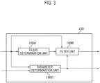
- FIG. 3 is a diagram illustrating an in-loop filter processing unit 150 according to the present embodiment.
- the in-loop filter processing unit 150 is capable of selecting either the application or non-application of adaptive loop filter processing in coding tree blocks (coding tree units (CTU)). Furthermore, when adaptive loop filter processing is applied, the in-loop filter processing unit 150 is capable of selecting usage of any filter set among a plurality of filter sets.
- CTU coding tree units
- the filter sets each include a filter for a maximum of 25 types (classes) of luma signal, and a filter for one class of chroma signal.
- Parameters that include information pertaining to the application or non-application of the adaptive loop filter processing and information pertaining to the filter set to be used for the adaptive loop filter processing, or the like, are encoded for each CTU as additional information and transmitted to the image decoding device 200, as will be described subsequently. Note that the parameters are determined by the parameter determination unit 150C, as will be described subsequently.
- the CTUs may be defined as blocks which are obtained by dividing a luma (Y) signal using a 128 ⁇ 128 pixel size and chroma (Cb, Cr) signals using a 64 ⁇ 64 pixel size, for example.
- the class determination unit 150A is configured to use, as an input, a decoded signal prior to the filtering process and to output class determination information indicating which type (class) of filter is to be used among a predetermined plurality of types of filters (adaptive loop filters).
- the class determination unit 150A is configured to divide the decoded signal prior to the filtering process into small blocks and determine the class to be used for each of the blocks.
- the class determination unit 150A is capable of determining, for each 4 ⁇ 4 pixel block, which class of filter is to be used from among 25 types.
- any determination method can be used as the class determination method as long as the method enables a determination to be made by using, as an input, only information that is obtained on both the image encoding device 100 side and the image decoding device 200 side.
- Non Patent Literature 1 the foregoing class determination is made by using the gradient of the pixel values of the decoded signal prior to the filtering process.
- the same class determination can be made on both the image decoding device 200 side and the image encoding device 100 side, and hence there is no need to transmit the class determination information from the image encoding device 100 side to the image decoding device 200 side.
- the filter unit 150B is configured to use a decoded signal prior to the filtering process as an input and to output a filtered decoded signal.
- the filter unit 150B is configured to perform filter processing by using, as an input, a decoded signal prior to the filtering process, class determination information outputted from the class determination unit 150A, and parameters (a loop filter processing parameter group) inputted from the parameter determination unit 150C, and to output a filtered decoded signal.
- each pixel of the filtered decoded signal can be calculated using the following equation, for example.
- O x ,y I x ,y + ⁇ i ,j ⁇ 0,0 C i ,j .
- I(x, y) is a pixel value of the decoded signal prior to the filtering process at a coordinate (x, y);
- O(x, y) is a pixel value of the filtered decoded signal at coordinate (x, y);
- (i, j) is a coordinate indicating the relative position of a reference pixel with respect to a pixel at coordinate (x, y) (a reference pixel position);
- C(i, j) is a filter coefficient corresponding to the reference pixel position (i, j);
- K() is clipping processing as indicated hereinbelow; and
- k(i j) is a threshold value used in the clipping processing.
- K() is processing that returns -k when the input value I is smaller than -k, returns k when the input value I is greater than k, and otherwise returns the input value I as is.
- the filter unit 150B is configured to perform the clipping processing with respect to the decoded signal prior to the filtering process so that the absolute value of a differential value between the reference pixel value I(x+i, y+j) and the pixel value I (x, y) of the decoded signal prior to the filtering process is less than or equal to the predefined threshold value k(i, j).
- the filter unit 150B is configured to generate the filtered decoded signal through the linear weighted addition of the value after the clipping processing is performed and the pixel value I(x, y) of the decoded signal prior to the filtering process.
- Fig. 4(a) illustrates an example of the arrangement of filter coefficients C in the filter processing of a luma signal
- Fig. 4(b) illustrates an example of the arrangement of filter coefficients C in the filter processing of a chroma signal.
- the other filter coefficients are similarly arranged with point symmetry so as to be centered on the pixel labeled X.
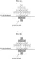
- filter processing can be achieved by copying (known as padding) a pixel value of a decoded signal prior to the filtering process located at the picture boundary.
- Fig. 5 illustrates an example of filter processing at the lower edge of the picture (at the picture boundary).
- the grayed-out filter coefficients C0 to C3 refer to pixels outside the picture. At such time, the same pixel value as the pixel value corresponding to filter coefficient C6 which is disposed directly above filter coefficient C2 in Fig. 5(a) is used as the input for the grayed-out filter coefficients C2 and C0.
- the same pixel value as the pixel value corresponding to filter coefficient C7, which is disposed directly above filter coefficient C3 in Fig. 5(a) , is used as the input for the grayed-out filter coefficient C3, and the same pixel value as the pixel value corresponding to filter coefficient C5, which is disposed directly above filter coefficient C1 in Fig. 5(a) , is used as the input for the grayed-out filter coefficient C1.
- a padded value when a padded value is used in one part of the reference pixel by considering the point symmetry of the foregoing filter coefficients C, a padded value can also be used as an input for a filter coefficient C in a position which corresponds to the reference pixel.
- a padded value may also be inputted for the grayed-out filter coefficients C0 to C3.
- a pixel value corresponding to the filter coefficient C6 directly below filter coefficient C2 may also be used as padding as an input for the filter coefficients C0 and C2 in Fig. 5(b) .
- pixel values corresponding to filter coefficients C5 and C7 directly below filter coefficients C1 and C3 may also be used as padding as an input for the filter coefficients C1 and C3, respectively.
- the foregoing filter processing method can be applied to similarly deal with a situation where pixel values cannot be referenced, not only at a picture boundary, but also beyond a boundary, such as a boundary of an encoding parallel processing unit known as a slice or a tile, or a boundary in pipeline processing known as a virtual boundary.
- a threshold value which is used in clipping processing, is set for each filter class and each filter coefficient C, respectively.
- the threshold values are determined by the parameter determination unit 150C, described subsequently, and transmitted to the image decoding device 200 side as additional information.
- the threshold values for the luma signal and the threshold values for the chroma signal can be defined as in Fig. 6 , for example.
- the variance of a luma signal tends to be larger than the variance of a chroma signal, and therefore, as illustrated in Fig. 6(a) , setting the threshold value for the luma signal as greater than or equal to the threshold value for the chroma signal enables clipping processing that takes into account the characteristics of each signal.
- the threshold value for the luma signal and the threshold value for the chroma signal may also be defined so as to be calculated by being respectively multiplied by the same scaling factor value according to the change in the internal bit depth.
- the large-small relationship between the threshold value for the luma signal and the threshold value for the chroma signal can be unchanged even when the internal bit depth is changed, and the same clipping processing can be performed irrespective of the internal bit depth.
- the threshold values for the luma signal and the threshold values for the chroma signal may each be defined so as to be calculated using bit-shifts according to the change in internal bit depth.
- the threshold value corresponding to the index 0 in Figs. 6(a) and 6(b) is the same value as the maximum value that can be achieved using the corresponding internal bit depth.
- the filter coefficient C corresponding to this threshold value is actually equivalent to not performing clipping processing.
- the threshold values can be defined so that the large-small relationship of the threshold values used in the clipping processing between the luma signal and chroma signal is immutable.
- a threshold value is set for each class and each filter coefficient C
- a method is also possible whereby the same threshold value is set for all the filter coefficients C for each class, for example, that is, the threshold values are set one by one for each class. In this case, because the number of threshold values to be transmitted decreases, the code amount pertaining to threshold value indices can be reduced.
- a flag indicating whether to perform clipping processing for each class is transmitted ahead of a threshold value index, when there is only one type of threshold value for each class, there is no need to define a threshold value corresponding to the foregoing index 0 (equivalent to no clipping processing).
- the possible patterns for threshold values can be reduced from four types to three types, a further reduction in the code amount pertaining to the threshold value indices is to be expected.
- the threshold value for the luma signal and the threshold value for the chroma signal may also be defined so as to be calculated by performing an arithmetic operation according to the current internal bit depth, based on a case where the internal bit depth is ten bits.
- Fig. 6(a) an example is illustrated in Fig. 6(a) where it is possible to obtain the final threshold values by multiplying same by a power of two according to the value of the current internal bit depth (bitdepth in Fig. 6 ), based on a case where there are four types of threshold values, namely, 1024, 181, 32, and 6 when the luma signal is ten bits and where there are four types of threshold values, namely, 1024, 161, 25, and 4 when the chroma signal is ten bits.
- threshold values when there are ten bits are expressed by numerical values (1024, 181, and so forth), the threshold values may also be defined using a mathematical formula.
- the parameters determined by the parameter determination unit 150C include the following, for example.
- the parameter determination unit 150C holds a plurality of filter sets for a certain frame and, as described subsequently, is capable of selecting usage of any filter set for each region.
- examples of such parameters include a flag indicating whether to apply an adaptive loop filter for each CTU, for example.
- the parameter determination unit 150C is capable of setting index information indicating which among the plurality of filter sets is to be used.
- the decoding unit 210 is configured to decode encoded data generated by the image encoding device 100 and decode a coefficient level value.
- the decoding unit 210 may be configured to acquire control data through decoding processing of the encoded data.
- control data may include size data such as an encoding block size, a prediction block size, and a transform block size.
- the inverse transformation/inverse quantization unit 220 is configured to perform inverse transformation processing of the coefficient level value output from the decoding unit 210.
- the inverse transformation/inverse quantization unit 220 may be configured to perform inverse quantization of the coefficient level value prior to the inverse transformation processing.
- the adder 230 is configured to add a prediction signal to a prediction remainder signal output from the inverse transformation/inverse quantization unit 220 to generate a decoded signal prior to the filtering process and output the decoded signal prior to the filtering process to the intra prediction unit 242 and the in-loop filter processing unit 250.
- the decoded signal prior to the filtering process configures a reference block used in the intra prediction unit 242.
- the inter prediction unit 241 is configured to generate a prediction signal through inter prediction (inter-frame prediction).
- the inter prediction unit 241 is configured to generate, for each prediction block, a prediction signal based on the motion vector decoded from the encoded data and the reference signal included in the reference frame.
- the inter prediction unit 241 is configured to output the prediction signal to the adder 230.
- the intra prediction unit 242 is configured to generate a prediction signal through intra prediction (intra-frame prediction).
- the intra prediction unit 242 is configured to specify a reference block included in a target frame and generate, for each prediction block, a prediction signal based on the specified reference block.
- the intra prediction unit 242 is configured to output the prediction signal to the adder 230.
- the frame buffer 260 is configured to accumulate the reference frame used in the inter prediction unit 241.
- the filtered decoded signal configures the reference frame used in the inter prediction unit 241.
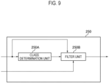
- FIG. 9 is a diagram illustrating an in-loop filter processing unit 250 according to the present embodiment.
- the in-loop filter processing unit 250 has a class determination unit 250A and a filter unit 250B.
- the class determination unit 250A is configured, like the class determination unit 150A, to use, as an input, a decoded signal prior to the filtering process and to output class determination information indicating which class of filter is to be used among a predetermined plurality of types of in-loop filters.
- the filter unit 250B is configured, like the filter unit 150B, to execute filter processing on the basis of the decoded signal prior to the filtering process, the class determination information determined by the class determination unit 250A, and the parameters transmitted as additional information from the image encoding device 100 side, and to output a filtered decoded signal.
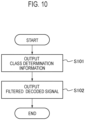
- Fig. 10 is a flowchart illustrating an example of a processing procedure of the in-loop filter processing unit 250 of the image decoding device 200 according to the present embodiment.
- the in-loop filter processing unit 250 uses the decoded signal prior to the filtering process as an input and outputs class determination information regarding which class of filter is to be used from among the predetermined plurality of types of in-loop filters.
- step S102 the in-loop filter processing unit 250 executes filter processing on the basis of the decoded signal prior to the filtering process, the class determination information determined by the class determination unit 250A, and the parameters transmitted as additional information from the image encoding device 100 side, and outputs a filtered decoded signal.
- the processing of threshold values for input signals of an adaptive interpolation filter is concerned, because the large-small relationship between a threshold value for a luma signal and a threshold value for a chroma signal is immutable when the dynamic ranges of the luma signal and the chroma signal are transformed so as to be the same irrespective of the internal bit depth setting, an unintended variation in the characteristics of the subjective image quality can be prevented.
- the image encoding device 10 and the image decoding device 30 described above may be realized by a program which causes a computer to execute functions (processes).
Landscapes
- Engineering & Computer Science (AREA)
- Multimedia (AREA)
- Signal Processing (AREA)
- Compression Or Coding Systems Of Tv Signals (AREA)
Applications Claiming Priority (3)
| Application Number | Priority Date | Filing Date | Title |
|---|---|---|---|
| JP2019114961A JP6811931B2 (ja) | 2019-06-20 | 2019-06-20 | 画像復号装置、画像復号方法及びプログラム |
| PCT/JP2020/022975 WO2020255847A1 (ja) | 2019-06-20 | 2020-06-11 | 画像復号装置、画像復号方法及びプログラム |
| EP20827571.9A EP3849195B1 (de) | 2019-06-20 | 2020-06-11 | Bilddekodierungsvorrichtung, bilddekodierungsverfahren, und programm |
Related Parent Applications (2)
| Application Number | Title | Priority Date | Filing Date |
|---|---|---|---|
| EP20827571.9A Division EP3849195B1 (de) | 2019-06-20 | 2020-06-11 | Bilddekodierungsvorrichtung, bilddekodierungsverfahren, und programm |
| EP20827571.9A Division-Into EP3849195B1 (de) | 2019-06-20 | 2020-06-11 | Bilddekodierungsvorrichtung, bilddekodierungsverfahren, und programm |
Publications (2)
| Publication Number | Publication Date |
|---|---|
| EP4521742A2 true EP4521742A2 (de) | 2025-03-12 |
| EP4521742A3 EP4521742A3 (de) | 2025-05-28 |
Family
ID=73994379
Family Applications (5)
| Application Number | Title | Priority Date | Filing Date |
|---|---|---|---|
| EP25154460.7A Pending EP4521743A3 (de) | 2019-06-20 | 2020-06-11 | Bilddecodierungsvorrichtung, bilddecodierungsverfahren und programm |
| EP25154461.5A Pending EP4521744A3 (de) | 2019-06-20 | 2020-06-11 | Bilddecodierungsvorrichtung, bilddecodierungsverfahren und programm |
| EP25154458.1A Pending EP4521741A3 (de) | 2019-06-20 | 2020-06-11 | Bilddecodierungsvorrichtung, bilddecodierungsverfahren und programm |
| EP20827571.9A Active EP3849195B1 (de) | 2019-06-20 | 2020-06-11 | Bilddekodierungsvorrichtung, bilddekodierungsverfahren, und programm |
| EP25154459.9A Pending EP4521742A3 (de) | 2019-06-20 | 2020-06-11 | Bilddecodierungsvorrichtung, bilddecodierungsverfahren und programm |
Family Applications Before (4)
| Application Number | Title | Priority Date | Filing Date |
|---|---|---|---|
| EP25154460.7A Pending EP4521743A3 (de) | 2019-06-20 | 2020-06-11 | Bilddecodierungsvorrichtung, bilddecodierungsverfahren und programm |
| EP25154461.5A Pending EP4521744A3 (de) | 2019-06-20 | 2020-06-11 | Bilddecodierungsvorrichtung, bilddecodierungsverfahren und programm |
| EP25154458.1A Pending EP4521741A3 (de) | 2019-06-20 | 2020-06-11 | Bilddecodierungsvorrichtung, bilddecodierungsverfahren und programm |
| EP20827571.9A Active EP3849195B1 (de) | 2019-06-20 | 2020-06-11 | Bilddekodierungsvorrichtung, bilddekodierungsverfahren, und programm |
Country Status (4)
| Country | Link |
|---|---|
| EP (5) | EP4521743A3 (de) |
| JP (1) | JP6811931B2 (de) |
| CN (5) | CN116916019A (de) |
| WO (1) | WO2020255847A1 (de) |
Families Citing this family (2)
| Publication number | Priority date | Publication date | Assignee | Title |
|---|---|---|---|---|
| CN117640930A (zh) * | 2019-06-24 | 2024-03-01 | 华为技术有限公司 | 用于非线性自适应环路滤波器的限幅电平 |
| WO2021134064A1 (en) * | 2019-12-28 | 2021-07-01 | Beijing Dajia Internet Information Technology Co., Ltd. | In-loop filters for video coding |
Family Cites Families (17)
| Publication number | Priority date | Publication date | Assignee | Title |
|---|---|---|---|---|
| US8184693B2 (en) * | 2008-04-11 | 2012-05-22 | Intel Corporation | Adaptive filtering for bit-depth scalable video codec |
| CN102057680A (zh) * | 2008-07-04 | 2011-05-11 | 株式会社东芝 | 运动图像编码/解码方法和装置 |
| EP2192786A1 (de) * | 2008-11-27 | 2010-06-02 | Panasonic Corporation | Frequenzbereichsfilter zur Videokodierung |
| CN102771109B (zh) * | 2010-02-22 | 2016-10-26 | 杜比实验室特许公司 | 通过盖写视频数据进行视频传递和控制的方法、设备和系统 |
| JP5073004B2 (ja) * | 2010-04-23 | 2012-11-14 | 株式会社東芝 | 画像符号化装置及び画像符号化方法並びに画像復号化装置及び画像復号化方法 |
| JP5875979B2 (ja) * | 2010-06-03 | 2016-03-02 | シャープ株式会社 | フィルタ装置、画像復号装置、画像符号化装置、および、フィルタパラメータのデータ構造 |
| JP2012065120A (ja) * | 2010-09-15 | 2012-03-29 | Sharp Corp | フィルタ係数設定装置、フィルタ係数設定方法、および、画像符号化装置 |
| US9185404B2 (en) * | 2011-10-07 | 2015-11-10 | Qualcomm Incorporated | Performing transform dependent de-blocking filtering |
| JP2013187868A (ja) * | 2012-03-09 | 2013-09-19 | Sharp Corp | 画像復号装置、画像符号化装置、およびデータ構造 |
| MX368598B (es) * | 2015-05-20 | 2019-10-08 | Ericsson Telefon Ab L M | Procesamiento y codificacion de pixeles. |
| JP6383327B2 (ja) * | 2015-06-10 | 2018-08-29 | 日本電信電話株式会社 | イントラ予測処理装置、イントラ予測処理方法、イントラ予測処理プログラム、画像符号化装置及び画像復号装置 |
| CN107736027B (zh) * | 2015-06-12 | 2021-06-01 | 松下知识产权经营株式会社 | 图像编码方法、图像解码方法、图像编码装置及图像解码装置 |
| PH12018500454B1 (en) * | 2015-09-03 | 2024-02-28 | Mediatek Inc | Method and apparatus of nueral network based processing in video coding |
| EP3244616A1 (de) * | 2016-05-13 | 2017-11-15 | Thomson Licensing | Anpassung der chrominanzwerte vor der kompression von video |
| CN109792541A (zh) * | 2016-10-05 | 2019-05-21 | 瑞典爱立信有限公司 | 用于视频译码的去振铃滤波器 |
| WO2019065487A1 (ja) * | 2017-09-28 | 2019-04-04 | シャープ株式会社 | 値制限フィルタ装置、動画像符号化装置および動画像復号装置 |
| GB2580173B (en) * | 2018-12-21 | 2022-07-27 | Canon Kk | A filter |
-
2019
- 2019-06-20 JP JP2019114961A patent/JP6811931B2/ja active Active
-
2020
- 2020-06-11 CN CN202311038454.3A patent/CN116916019A/zh active Pending
- 2020-06-11 EP EP25154460.7A patent/EP4521743A3/de active Pending
- 2020-06-11 EP EP25154461.5A patent/EP4521744A3/de active Pending
- 2020-06-11 EP EP25154458.1A patent/EP4521741A3/de active Pending
- 2020-06-11 CN CN202080004683.1A patent/CN112616326B/zh active Active
- 2020-06-11 CN CN202311040097.4A patent/CN116916020A/zh active Pending
- 2020-06-11 CN CN202311043605.4A patent/CN116916021A/zh active Pending
- 2020-06-11 WO PCT/JP2020/022975 patent/WO2020255847A1/ja not_active Ceased
- 2020-06-11 CN CN202311043613.9A patent/CN116916022B/zh active Active
- 2020-06-11 EP EP20827571.9A patent/EP3849195B1/de active Active
- 2020-06-11 EP EP25154459.9A patent/EP4521742A3/de active Pending
Also Published As
| Publication number | Publication date |
|---|---|
| CN116916020A (zh) | 2023-10-20 |
| CN116916019A (zh) | 2023-10-20 |
| CN112616326A (zh) | 2021-04-06 |
| EP3849195A1 (de) | 2021-07-14 |
| CN116916021A (zh) | 2023-10-20 |
| EP4521744A3 (de) | 2025-05-28 |
| JP2021002726A (ja) | 2021-01-07 |
| CN116916022B (zh) | 2026-04-17 |
| EP4521744A2 (de) | 2025-03-12 |
| EP4521743A3 (de) | 2025-05-28 |
| EP4521741A2 (de) | 2025-03-12 |
| WO2020255847A1 (ja) | 2020-12-24 |
| JP6811931B2 (ja) | 2021-01-13 |
| EP4521742A3 (de) | 2025-05-28 |
| CN112616326B (zh) | 2023-09-12 |
| EP4521741A3 (de) | 2025-05-28 |
| EP3849195A4 (de) | 2022-08-03 |
| EP3849195B1 (de) | 2025-03-12 |
| CN116916022A (zh) | 2023-10-20 |
| EP4521743A2 (de) | 2025-03-12 |
Similar Documents
| Publication | Publication Date | Title |
|---|---|---|
| US11736689B2 (en) | Encoding device, decoding device, encoding method, and decoding method | |
| EP3989544A1 (de) | Bilddecodierungsvorrichtung, bilddecodierungsverfahren und programm | |
| JP5502336B2 (ja) | 映像信号符号化装置及び、映像信号符号化方法 | |
| CN109792541A (zh) | 用于视频译码的去振铃滤波器 | |
| JP7749153B2 (ja) | 符号化装置、復号装置、及びプログラム | |
| EP3849195B1 (de) | Bilddekodierungsvorrichtung, bilddekodierungsverfahren, und programm | |
| US20250159155A1 (en) | Image decoding device, image decoding method, and program | |
| JP7485838B2 (ja) | 画像復号装置、画像復号方法及びプログラム | |
| EP3343919B1 (de) | Videocodierungsvorrichtung, videocodierungsverfahren, videodecodierungsvorrichtung und videodecodierungsverfahren | |
| JP6941752B1 (ja) | 画像復号装置、画像復号方法及びプログラム | |
| EP4460968A1 (de) | Filterung zur bildcodierung und -decodierung | |
| CN116527902B (zh) | 图像加权量化处理方法、装置、计算机设备和存储介质 | |
| HK1087227A1 (zh) | 用於提高低比特率视频的视频质量的方法和装置 | |
| HK1087227B (en) | Method and apparatus for improving video quality of low bit-rate video |
Legal Events
| Date | Code | Title | Description |
|---|---|---|---|
| PUAI | Public reference made under article 153(3) epc to a published international application that has entered the european phase |
Free format text: ORIGINAL CODE: 0009012 |
|
| STAA | Information on the status of an ep patent application or granted ep patent |
Free format text: STATUS: THE APPLICATION HAS BEEN PUBLISHED |
|
| AC | Divisional application: reference to earlier application |
Ref document number: 3849195 Country of ref document: EP Kind code of ref document: P |
|
| AK | Designated contracting states |
Kind code of ref document: A2 Designated state(s): AL AT BE BG CH CY CZ DE DK EE ES FI FR GB GR HR HU IE IS IT LI LT LU LV MC MK MT NL NO PL PT RO RS SE SI SK SM TR |
|
| REG | Reference to a national code |
Ref country code: DE Ref legal event code: R079 Free format text: PREVIOUS MAIN CLASS: H04N0019186000 Ipc: H04N0019820000 |
|
| PUAL | Search report despatched |
Free format text: ORIGINAL CODE: 0009013 |
|
| AK | Designated contracting states |
Kind code of ref document: A3 Designated state(s): AL AT BE BG CH CY CZ DE DK EE ES FI FR GB GR HR HU IE IS IT LI LT LU LV MC MK MT NL NO PL PT RO RS SE SI SK SM TR |
|
| RIC1 | Information provided on ipc code assigned before grant |
Ipc: H04N 19/186 20140101ALI20250424BHEP Ipc: H04N 19/14 20140101ALI20250424BHEP Ipc: H04N 19/134 20140101ALI20250424BHEP Ipc: H04N 19/117 20140101ALI20250424BHEP Ipc: H04N 19/82 20140101AFI20250424BHEP |
|
| STAA | Information on the status of an ep patent application or granted ep patent |
Free format text: STATUS: REQUEST FOR EXAMINATION WAS MADE |
|
| 17P | Request for examination filed |
Effective date: 20251010 |