EP4521140A1 - Signalübertragungs-/empfangssystem und -verfahren - Google Patents
Signalübertragungs-/empfangssystem und -verfahren Download PDFInfo
- Publication number
- EP4521140A1 EP4521140A1 EP22939717.9A EP22939717A EP4521140A1 EP 4521140 A1 EP4521140 A1 EP 4521140A1 EP 22939717 A EP22939717 A EP 22939717A EP 4521140 A1 EP4521140 A1 EP 4521140A1
- Authority
- EP
- European Patent Office
- Prior art keywords
- time point
- delay
- signal
- determining
- point
- Prior art date
- Legal status (The legal status is an assumption and is not a legal conclusion. Google has not performed a legal analysis and makes no representation as to the accuracy of the status listed.)
- Pending
Links
Images




Classifications
-
- G—PHYSICS
- G01—MEASURING; TESTING
- G01S—RADIO DIRECTION-FINDING; RADIO NAVIGATION; DETERMINING DISTANCE OR VELOCITY BY USE OF RADIO WAVES; LOCATING OR PRESENCE-DETECTING BY USE OF THE REFLECTION OR RERADIATION OF RADIO WAVES; ANALOGOUS ARRANGEMENTS USING OTHER WAVES
- G01S7/00—Details of systems according to groups G01S13/00, G01S15/00, G01S17/00
- G01S7/48—Details of systems according to groups G01S13/00, G01S15/00, G01S17/00 of systems according to group G01S17/00
- G01S7/483—Details of pulse systems
- G01S7/484—Transmitters
-
- G—PHYSICS
- G01—MEASURING; TESTING
- G01S—RADIO DIRECTION-FINDING; RADIO NAVIGATION; DETERMINING DISTANCE OR VELOCITY BY USE OF RADIO WAVES; LOCATING OR PRESENCE-DETECTING BY USE OF THE REFLECTION OR RERADIATION OF RADIO WAVES; ANALOGOUS ARRANGEMENTS USING OTHER WAVES
- G01S17/00—Systems using the reflection or reradiation of electromagnetic waves other than radio waves, e.g. lidar systems
- G01S17/02—Systems using the reflection of electromagnetic waves other than radio waves
- G01S17/06—Systems determining position data of a target
- G01S17/08—Systems determining position data of a target for measuring distance only
- G01S17/10—Systems determining position data of a target for measuring distance only using transmission of interrupted, pulse-modulated waves
- G01S17/14—Systems determining position data of a target for measuring distance only using transmission of interrupted, pulse-modulated waves wherein a voltage or current pulse is initiated and terminated in accordance with the pulse transmission and echo reception respectively, e.g. using counters
-
- G—PHYSICS
- G01—MEASURING; TESTING
- G01S—RADIO DIRECTION-FINDING; RADIO NAVIGATION; DETERMINING DISTANCE OR VELOCITY BY USE OF RADIO WAVES; LOCATING OR PRESENCE-DETECTING BY USE OF THE REFLECTION OR RERADIATION OF RADIO WAVES; ANALOGOUS ARRANGEMENTS USING OTHER WAVES
- G01S7/00—Details of systems according to groups G01S13/00, G01S15/00, G01S17/00
- G01S7/02—Details of systems according to groups G01S13/00, G01S15/00, G01S17/00 of systems according to group G01S13/00
-
- G—PHYSICS
- G01—MEASURING; TESTING
- G01S—RADIO DIRECTION-FINDING; RADIO NAVIGATION; DETERMINING DISTANCE OR VELOCITY BY USE OF RADIO WAVES; LOCATING OR PRESENCE-DETECTING BY USE OF THE REFLECTION OR RERADIATION OF RADIO WAVES; ANALOGOUS ARRANGEMENTS USING OTHER WAVES
- G01S7/00—Details of systems according to groups G01S13/00, G01S15/00, G01S17/00
- G01S7/48—Details of systems according to groups G01S13/00, G01S15/00, G01S17/00 of systems according to group G01S17/00
- G01S7/483—Details of pulse systems
- G01S7/486—Receivers
- G01S7/4865—Time delay measurement, e.g. time-of-flight measurement, time of arrival measurement or determining the exact position of a peak
-
- G—PHYSICS
- G01—MEASURING; TESTING
- G01S—RADIO DIRECTION-FINDING; RADIO NAVIGATION; DETERMINING DISTANCE OR VELOCITY BY USE OF RADIO WAVES; LOCATING OR PRESENCE-DETECTING BY USE OF THE REFLECTION OR RERADIATION OF RADIO WAVES; ANALOGOUS ARRANGEMENTS USING OTHER WAVES
- G01S7/00—Details of systems according to groups G01S13/00, G01S15/00, G01S17/00
- G01S7/48—Details of systems according to groups G01S13/00, G01S15/00, G01S17/00 of systems according to group G01S17/00
- G01S7/497—Means for monitoring or calibrating
-
- G—PHYSICS
- G01—MEASURING; TESTING
- G01S—RADIO DIRECTION-FINDING; RADIO NAVIGATION; DETERMINING DISTANCE OR VELOCITY BY USE OF RADIO WAVES; LOCATING OR PRESENCE-DETECTING BY USE OF THE REFLECTION OR RERADIATION OF RADIO WAVES; ANALOGOUS ARRANGEMENTS USING OTHER WAVES
- G01S7/00—Details of systems according to groups G01S13/00, G01S15/00, G01S17/00
- G01S7/48—Details of systems according to groups G01S13/00, G01S15/00, G01S17/00 of systems according to group G01S17/00
- G01S7/483—Details of pulse systems
- G01S7/486—Receivers
- G01S7/4861—Circuits for detection, sampling, integration or read-out
Definitions
- This disclosure relates to a signal transmitting and receiving system and a method thereof and, in particular, to a system and a method for stabilization of a scanning start point in a receiving system and a transmitting system with asynchronous clocks.
- a signal transmitting and receiving system is a common means of detecting a target object. By transmitting a signal to the target object and detecting a reflected echo signal, detection and measurement of the target object is realized.
- a typical application example includes a LiDAR detects the target object by emitting a laser beam, and calculates accurate distance, orientation, reflectivity and other information of at least one of the target object or area based on an echo signal reflected by a detected target object. Compared with other technologies, the LiDAR can better characterize a complex earth surface state, and the LiDAR is increasingly widely used in ranging applications such as distance measurement in fields of automobile driving and industrial automation, and has great market development prospects.
- an emitter of the LiDAR typically transmits an explosive energy signal emitted by a laser pulse, and after the explosive energy signal reflected by a reflective surface, part of the energy is absorbed to generate an attenuated and delayed LiDAR signal, which is superimposed on an original signal to form an echo.
- an echo processing chip separate from a transmitting and receiving chip is provided, forming an asynchronous clock system.
- the echo processing chip need to detect a reference signal ("kick") sent by the transmitting and receiving chip to start scanning.
- An asynchronous clock cannot guarantee a phase relationship between a kick signal and a receiving clock (“clk”) to meet needs of setup time (“Tsu”) and hold time (“Th”). Accordingly, there is a certain probability of occurrence of metastability in detecting the kick signal.
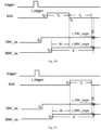
- Figs. 1A and 1B respectively show two cases in which the metastability occurs for the kick signal.
- kick' represents a signal with the metastability
- kick" represents a signal after one flip-flop is made to eliminate the metastability.
- a jitter of 1 ns may cause a position jitter of a detected object of 15 cm, which is unacceptable for a LiDAR with accuracy of 2 to 3 cm. Accordingly, it is beneficial to solve a problem of an unstable scanning start point for an asynchronous clock receiving system for signal transmission and reception to ensure accuracy of object detection.
- the transmitter circuit further generates a reference signal, and the reference signal has a fixed time sequence relationship with the transmitting time point; and the determining the first calculation start point further includes: determining, by the first receiving channel, a reference time point based on the reference signal, and determining the first calculation start point based on the reference time point.
- the determining the first calculation start point based on the reference time point includes determining an expected scanning delay, where the expected scanning delay is a delay of a preset duration after the reference time point; and the first receiving channel taking the initial start time point as the time origin: determining an initial timing time point; determining a compensation delay based on the initial timing time point and the reference time point, where the compensation delay includes a canceling part for the jitter delay; and determining the first calculation start point based on the initial timing time point and the compensation delay.
- the determining the initial timing time point includes: determining the initial timing time point based on the initial start time point.
- the receiver circuit further includes a second receiving channel, and the second receiving channel is enabled at a first start time point and configured to sense the echo signal; and the determining the initial timing time point includes: determining the initial timing time point based on the first start time point.
- the determining the first calculation start point based on the initial timing time point and the compensation delay includes determining a system comprehensive delay, and determining a second delay based on the compensation delay, the expected scanning delay, and the system comprehensive delay; and determining the first calculation start point based on the initial timing time point and the second delay.
- the receiver circuit further determines a second calculation start point of the second receiving channel based on the second delay, and determines the target time difference between a return time point of the echo signal sensed by the second receiving channel and the transmitting time point based on the second calculation start point.
- the receiver circuit further includes a second receiving channel, and the second receiving channel enables a pre-enable signal at the first start time point and enables an enable signal at the second start time point, where the enable signal of the second receiving channel is configured to sense the echo signal; and the determining the initial timing time point includes: determining the initial timing time point based on the first start time point.
- the determining the first calculation start point based on the initial timing time point and the compensation delay includes determining the system comprehensive delay, determining the second delay based on the compensation delay, the expected scanning delay, and the system comprehensive delay, and determining the first calculation start point based on the initial timing time point and the second delay.
- the receiver circuit further determines the second calculation start point of the enable signal of the second receiving channel based on the first start time point and the second delay, and determines the target time difference between the return time point of the echo signal sensed by the enable signal and the transmitting time point based on the second calculation start point.
- determining the system comprehensive delay includes: selecting a value of the system comprehensive delay of a previous scan as a value of the system comprehensive delay of a current scan; and the determining the first calculation start point includes: determining an initial second delay by summing the compensation delay, the expected scanning delay, and the system comprehensive delay of the current scan; determining an integer time unit value by rounding a value of the initial second delay; determining the integer time unit value as a value of the second delay of the current scan; updating the system comprehensive delay of the current scan based on the value of the second delay of the current scan; and determining the first calculation start point by summing the initial timing time point and the second delay at a current time point.
- the trigger signal is the reference signal; and the trigger time point is a rising edge time point of the reference signal, and the reference time point is a falling edge time point of the reference signal.
- the trigger signal is different from the reference signal, and has the fixed time sequence relationship with the reference signal; and the trigger time point is earlier than the rising edge time point of the reference signal, and the reference time point is the rising edge time point or the falling edge time point of the reference signal.
- this disclosure discloses a signal transmitting and receiving method, including: generating a trigger signal at a trigger time point based on a first clock signal by a transmitter circuit and transmitting a detection signal at a transmitting time point; and receiving an echo signal generated by reflection of the detection signal by a target object by a receiver circuit, and receiving the trigger signal based on a second clock signal and enabling a first receiving channel at an initial start time point, where the first receiving channel takes the initial start time point as a time origin and senses a return time point of receiving the echo signal: determining a first calculation start point of the first receiving channel, and determining a target time difference between the return time point sensed by the first receiving channel and the transmitting time point based on the first calculation start point, where a first delay between the initial start time point and the trigger time point includes an unpredictable jitter delay.
- determining the target time difference between the return time point sensed by the first receiving channel and the transmitting time point based on the first calculation start point includes: determining a first time difference between the first calculation start point and the return time point; and determining the target time difference by summing the first time difference with a pre-calibrated time calibration value.
- the transmitter circuit further generates a reference signal, and the reference signal has a fixed time sequence relationship with the transmitting time point; and determining the first calculation start point further includes: determining, by the first receiving channel, a reference time point based on the reference signal, and determining the first calculation start point based on the reference time point.
- determining the first calculation start point based on the reference time point includes determining an expected scanning delay, where the expected scanning delay is a delay of a preset duration after the reference time point; and the first receiving channel taking the initial start time point as the time origin: determining an initial timing time point; determining a compensation delay based on the initial timing time point and the reference time point, where the compensation delay includes a canceling part for the jitter delay; and determining the first calculation start point based on the initial timing time point and the compensation delay.
- determining the initial timing time point includes: determining the initial timing time point based on the initial start time point.
- the receiver circuit further includes a second receiving channel, and the second receiving channel is enabled at a first start time point and configured to sense the echo signal; and determining the initial timing time point includes: determining the initial timing time point based on the first start time point.
- determining the first calculation start point based on the initial timing time point and the compensation delay includes determining a system comprehensive delay, determining a second delay based on the compensation delay, the expected scanning delay, and the system comprehensive delay; and determining the first calculation start point based on the initial timing time point and the second delay.
- the receiver circuit further determines a second calculation start point of the second receiving channel based on the first start time point and the second delay, and determines the target time difference between a return time point of the echo signal sensed by the second receiving channel and the transmitting time point based on the second calculation start point.
- the receiver circuit further includes a second receiving channel, and the second receiving channel enables a pre-enable signal at the first start time point and enables an enable signal at the second start time point, where the enable signal of the second receiving channel is configured to sense the echo signal; and determining the initial timing time point includes: determining the initial timing time point based on the first start time point.
- determining the first calculation start point based on the initial timing time point and the compensation delay includes determining the system comprehensive delay, determining the second delay based on the compensation delay, the expected scanning delay, and the system comprehensive delay, and determining the first calculation start point based on the initial timing time point and the second delay.
- the receiver circuit further determines the second calculation start point of the enable signal of the second receiving channel based on the first start time point and the second delay, and determines the target time difference between the return time point of the echo signal sensed by the enable signal and the transmitting time point based on the second calculation start point.
- determining the system comprehensive delay includes: selecting a value of the system comprehensive delay of a previous scan as a value of the system comprehensive delay of a current scan; and determining the first calculation start point includes: determining an initial second delay by summing the compensation delay, the expected scanning delay, and the system comprehensive delay of the current scan; determining an integer time unit value by rounding a value of the initial second delay; determining the integer time unit value as a value of the second delay of the current scan; updating the system comprehensive delay of the current scan based on the value of the second delay of the current scan; and determining the first calculation start point by summing the initial timing time point and the second delay at a current time point.
- the trigger signal is the reference signal; and the trigger time point is a rising edge time point of the reference signal, and the reference time point is a falling edge time point of the reference signal.
- the trigger signal is different from the reference signal, and has the fixed time sequence relationship with the reference signal; and the trigger time point is earlier than the rising edge time point of the reference signal, and the reference time point is the rising edge time point or the falling edge time point of the reference signal.
- a determined calculation start point of the receiving system is not influenced by cross clock domain metastability of the receiving system and the transmitting system, and a stability mechanism principle and a calculation method of a calculation start point of this disclosure are simple and easy to realize, thereby improving accuracy of time measurement and precision of a ranging system. And it is possible to accumulate scanning data in multiple scans in a chip, thereby further increasing a signal-to-noise ratio and improving a ranging capability and application scenarios of a receiving chip. In addition, the system and the method in this disclosure reasonably use existing hardware resources of the chip and it is not beneficial to determine additional devices to stabilize a scanning start point of the receiving system.
- Signal transmitting and receiving system 100; transmitter circuit: 110; first clock signal: 111; receiver circuit: 120; second clock signal: 121; receiving channel: 122; histogram sampler: HDC; time-to-digital converter: TDC; transmitting time point: t 0 ; initial start time point: t 0 ⁇ ; first calculation start point: t_TDC_origin; second calculation start point: t_HDC_origin; return time point: t 4 ; target time difference: TOF; reference time point:t 2 ; initial time point: t 1 ; expected scanning delay: T 1 ; system comprehensive delay: ⁇ t; second delay: x; compensation delay: ⁇ t; TDC time calibration value: t_TDC_c; HDC time calibration value: t_HDC_c; reference signal: kick; and trigger time point: t_trigger.
- Fig. 2 shows a schematic structural diagram of a signal transmitting and receiving system 100, provided in some embodiments of this specification.
- the signal can be a laser signal.
- the system 100 is an electromagnetic wave radar system
- the signal can be an electromagnetic wave.
- the system 100 is an ultrasonic radar system
- the signal can be an ultrasonic signal.
- the system 100 can also be a quantum detection system, and a signal can be a detection signal related to a quantum detection principle.
- the system 100 can also be the signal transmitting and receiving system in other forms, which is not limited in this disclosure.
- technical solutions of this disclosure can be illustrated by taking the LiDAR as an example. However, the technical solutions can be applied to the above other examples based on the technical solutions of this disclosure by those skilled in the art without departing from the spirit and essence of this disclosure.
- the signal transmitting and receiving system 100 includes a transmitter circuit 110 and a receiver circuit 120.
- the transmitter circuit 110 and the receiver circuit 120 are two independently operated circuits, which operate based on different clock signals.
- the transmitter circuit 110 can be a transmitter circuit or a transmitting chip of the LiDAR. Under a normal working condition, the laser transmitter circuit or the transmitting chip can output a laser pulse at a certain frequency.
- the receiver circuit 120 can be a receiver circuit or a receiving chip of the LiDAR.
- the receiver circuit or the receiving chip can receive an echo signal reflected by a target object, and calculate a time of flight ("TOF") or a target time difference of each laser pulse based on a transmitting time point of transmitting the laser pulse and a return time point of receiving the echo signal.
- TOF time of flight
- the transmitter circuit 110 includes a first clock signal 111.
- the transmitter circuit 110 transmits the detection signal at a transmitting time point t 0 based on the first clock signal 111. Because the transmitter circuit 110 and the receiver circuit 120 operate based on different clock signals, the transmitter circuit 110 also transmits a trigger signal to the receiver circuit 120 to enable the receiver circuit 120 to start scanning of the echo signal. Accordingly, the transmitter circuit 110 can generate the trigger signal at a time point t_trigger based on the first clock signal 111 and transmit the trigger signal to the receiver circuit 120 to enable a receiving channel 122, to cause the receiver circuit 120 to be ready to receive the echo signal.
- the echo signal is a signal generated by reflection of the detection signal by the target object.
- the echo signal is the laser reflected back after the emitted laser incident on the objects surrounding the LiDAR and is captured by the LiDAR.
- the trigger signal can be a kick signal as a reference signal or other trigger signals different from the reference signal.
- t_trigger generation and transmitting time point of the trigger signal and the transmitting time point t 0 of the detection signal, for example, t 0 is at a certain time point after the time point t_trigger, or t 0 and t_trigger can also be a same time point. This is described in detail later in this specification.
- the receiver circuit 120 includes a second clock signal 121 and the receiving channel 122.
- the receiver circuit 120 can detect the trigger signal transmitted by the transmitter circuit based on the second clock signal 121. By receiving the trigger signal, the receiver circuit 120 can enable the receiving channel 122 to start timing and detect the echo signal.
- the receiving channel 122 can include one receiving channel or multiple receiving channels, such as a time-to-digital converter ("TDC"), or a time-to-digital converter (“TDC”) and a histogram sampler (“HDC”), and TDC and HDC are both original receiving channels in a LiDAR transmitter circuit/chip.
- TDC and HDC each have their own measurement advantages. TDC is more suitable for measurement of nearby large signals and HDC is more suitable for measurement of distant small signals.
- the echo signal can be detected by using both TDC and HDC, and then fusion processing of point cloud data can be performed, more accurate echo signal data can be determined.
- Fig. 3 shows a workflow 300 of a signal transmitting and receiving system 100, provided in some embodiments of this disclosure, and the workflow 300 includes the following steps.
- the transmitter circuit generates the trigger signal at the trigger time point based on the first clock signal, and transmits the detection signal at the transmitting time point.
- the transmitter circuit 110 can generate the trigger signal at the trigger time point t_trigger based on the first clock signal 111, and transmit the trigger signal to the receiver circuit 120 to enable the receiving channel 122.
- the trigger signal can be a reference signal kick.
- a generation and transmitting time point t_trigger of a rising edge of the reference signal kick and a the transmitting time point t 0 of the detection signal can be a same time point or different time points, for example, the transmitting time point t 0 can be a certain time point after the rising edge of the reference signal kick.
- the receiver circuit receives the trigger signal based on the second clock signal, and enables the first receiving channel at an initial start time point.
- the receiver circuit 120 can determine an enable time point, that is, the initial start time point t 0 ⁇ , of the receiving channel 122 based on the second clock signal 121, and the receiving channel 122 performs detection of the echo signal by taking the initial start time point t 0 ⁇ as its time origin.
- the trigger signal can be the reference signal kick or other trigger signals different from the reference signal kick, and thus, the receiver circuit 120 can enable the receiving channel based on the reference signal kick, or can enable the receiving channel based on other trigger signals.
- the receiving channel 122 can merely include the first receiving channel, such as a time-to-digital converter TDC in Fig. 4 .
- the receiving channel 122 can also include both the first receiving channel, such as the time-to-digital converter TDC in Figs. 5A-C , and the second receiving channel, such as a histogram sampler HDC in Figs. 5A-C .
- the first receiving channel and the second receiving channel can both sense the echo signal independently.
- the receiving channel can also be other types of measurement channels except TDC and HDC, and the receiver circuit can also include more than two receiving channels, which can be fully applied to other examples based on the technical solutions of this disclosure by those skilled in the art based on essence and spirit of this disclosure.
- a TDC enable signal is represented as TDC_en in Fig. 4 , Fig. 5A-C , and Figs.6A-C .
- the receiver circuit 120 can enable the second receiving channel HDC after the initial start time point t 0 ⁇ , and enable HDC at an initial timing time point t 1 .
- the TDC can sense the initial timing time point t 1 , a reference time point t 2 , and a return time point t 4 of receiving the echo signal.
- Figs. 5A-C the receiver circuit 120 can enable the second receiving channel HDC after the initial start time point t 0 ⁇ , and enable HDC at an initial timing time point t 1 .
- the TDC can sense the initial timing time point t 1 , a reference time point t 2 , and a return time point t 4 of receiving the echo signal.
- the receiver circuit 120 can control the second receiving channel to generate a HDC pre-enable signal (HDC_en_pre) after the initial start time point t 0 ⁇ , for example, enable HDC_en_pre at a first start time point t 1 , and the receiver circuit 120 controls the second receiving channel HDC to enable a HDC enable signal (HDC_en) at a second calculation start point t_HDC_origin, and HDC_en can sense the echo signal.
- HDC_en_pre HDC pre-enable signal
- the receiving chip has a certain probability of occurrence of metastability when synchronizing the trigger signal (e.g., the reference signal kick)
- the trigger signal e.g., the reference signal kick
- the receiving channel detects the echo signal with the initial start time point t 0 ⁇ as its time origin, the unpredictable jitter delay can result in instability of a time origin for measuring the echo signal, thereby making a measurement result of the echo signal unstable.
- the first receiving channel senses the return time point of receiving the echo signal with the initial start time point as the time origin, and the receiver circuit determines a first calculation start point of the first receiving channel.
- the first receiving channel is activated at the initial start time point t 0 ⁇ , all subsequent time and time calculations are measured and calculated with the initial start time point t 0 ⁇ as the time origin for the first receiving channel.
- the first receiving channel can firstly determine the reference time point t 2 based on the reference signal kick, and then determine the first calculation start point t_TDC_origin based on the reference time point.
- the receiver circuit can determine an expected scanning delay T 1 and a system comprehensive delay ⁇ t, and the first receiving channel can determine the initial timing time point t 1 and the reference time point t 2 with the initial start time point t 0 ⁇ as the time origin.
- the initial timing time point t 1 can be determined based on the initial start time point t 0 ⁇ .
- the initial timing time point t 1 is the initial start time point t 0 ⁇ .
- the receiver circuit 120 includes both the first receiving channel and the second receiving channel, and the second receiving channel is enabled at the first start time point, and the first receiving channel determines the initial timing time point t 1 based on the first start time point.
- the first start time point is the initial timing time point t 1 .
- the receiver circuit 120 includes both the first receiving channel and the second receiving channel, and the second receiving channel enables the pre-enable signal HDC_en_pre at the first start time point and enables the enable signal HDC_en at the second start time point.
- the first receiving channel determines the initial timing time point based on the first start time point. In some embodiments, the first start time point is the initial timing time point t 1 .
- the expected scanning delay T 1 is a delay of a preset duration after the reference time point t 2 .
- the expected scanning delay T 1 can be determined by a system, and specific value of the expected scanning delay T 1 can be determined by testing.
- the expected scanning delay T 1 can be determined to a value greater than or equal to zero, for example, in a case of merely the first receiving channel ( Fig. 4 ) or in a case of the second receiving channel merely enabling the enable signal HDC_en ( Figs. 5A-C ).
- the expected scanning delay T 1 can be determined to a value greater than zero.
- the reference time point t 2 can be a falling edge time point of the reference signal kick. In other embodiments, the reference time point t 2 can be the rising edge time point of the reference signal kick.
- the first receiving channel can sense a falling edge time point of the reference signal kick as the reference time point t 2 ( Figs. 4, 5A , 5B , 6A, and 6B ), and can also sense the rising edge time point of the reference signal kick as the reference time point ( Figs. 5C and 6C ).
- the reference time point t 2 includes a negative jitter error relative to the initial start time point t 0 ⁇ , thereby canceling an influence of a jitter delay of the initial start time point t 0 ⁇ .
- the receiver circuit can determine a compensation delay ⁇ t based on the initial timing time point t 1 and the reference time point t 2 .
- the compensation delay ⁇ t is a time difference between the reference time point t 2 and the initial timing time point t 1 . Because time difference between the initial timing time point t 1 and the initial start time point t 0 ⁇ is generally fixed, the compensation delay ⁇ t includes a canceling part for the jitter delay.
- the receiver circuit 120 is formed of multiple electrical elements, and each electrical element can have its own errors due to manufacturing, calibration, thermal drift, and other reasons when processing a signal response. These errors can accumulate and result in a system comprehensive delay ⁇ t of the receiver circuit 120 in response. Accordingly, in addition to determining the reference time point t 2 and the compensation delay ⁇ t, the receiver circuit 120 also determines the system comprehensive delay ⁇ t by means of iteration. The method is specifically as follows.
- a value of an initial comprehensive delay is determined, and a preset expected scanning delay T 1 is retrieved. Then, at the beginning of each iteration, a value of the system comprehensive delay of a previous scan is selected as a value of the system comprehensive delay value of a current scan.
- the value of the system comprehensive delay of the current scan is the value of the initial comprehensive delay, and in some embodiments, the value of the initial comprehensive delay is zero.
- the compensation delay ⁇ t, the expected scanning delay T 1 , and the system comprehensive delay ⁇ t of the current scan are summed to determine an initial second delay x, a value of the initial second delay x is rounded to determine an integer time unit value, the integer time unit value is determined as the value of the second delay x, and the system comprehensive delay ⁇ t of the current scan is updated based on the value of the second delay x.
- the receiver circuit 120 can determine the first calculation start point based on the initial timing time point and the second delay x.
- the first calculation start point is a sum of the initial timing t 1 and the second delay x, that is, a time point determined by delaying of an enable time point of TDC_en of the first receiving channel by t 1 +x is the first calculation start point t_TDC_origin of the first receiving channel.
- the receiver circuit 120 further includes the second receiving channel, and thus step S330 further includes step S331.
- the receiver circuit 120 further includes the second receiving channel, and thus the receiver circuit determines the second calculation start point t_HDC_origin.
- the second receiving channel merely has the enable signal HDC_en, and the second receiving channel measures the echo signal with the enable time point of the enable signal HDC_en as its time origin.
- the receiver circuit determines the second calculation start point based on the second delay. Specifically, a time point determined by delaying the enable time point of HDC_en of the second receiving channel by the second delay x is the second calculation start point t_HDC_origin of the second receiving channel.
- the second receiving channel detects the echo signal with its enable time point as the time origin, after the second calculation start point t_HDC_origin is determined, the return time point is recalculated with the second calculation start point t_HDC_origin, and a value of the second calculation start point t_HDC_origin (i.e., x) should be subtracted from the return time point measured by HDC.
- the second receiving channel has the pre-enable signal HDC_en_pre and the enable signal HDC_en. The receiver circuit determines the second calculation start point based on the second delay.
- the second receiving channel is enabled at the time determined by delaying the enable time point of HDC_en_pre by the second delay, which is the second calculation start point t_HDC_origin of the second receiving channel.
- the second calculation start point is the enable time point of HDC_en
- the second receiving channel measures the echo signal with the second calculation start point as the time origin.
- the trigger signal trigger and the reference signal kick can be two different signals.
- the transmitter circuit provides the trigger signal trigger before the reference signal kick.
- a delay between the trigger signal trigger and the reference signal kick is fixed, to cause a receiving channel of the receiver circuit 120 to be triggered before arrival of the reference signal kick, and the reference time point t 2 can be determined by measuring the falling edge of the reference signal kick.
- the trigger signal trigger and the reference signal kick can be two different signals.
- the transmitter circuit 110 provides the trigger signal trigger before the reference signal kick, to cause the receiving channel to be triggered before the arrival of the reference signal kick.
- the receiver circuit can determine the reference time point t 2 by measuring the rising edge of the reference signal kick.
- the trigger signal trigger and the reference signal kick can be two different signals.
- the transmitter circuit provides the trigger signal trigger before the reference signal kick.
- the delay between the trigger signal trigger and the reference signal kick is fixed, to cause TDC and HDC of the receiver circuit 120 to be triggered before the arrival of the reference signal kick, and the reference time point t 2 can be determined by measuring the falling edge of the reference signal kick.
- the trigger signal trigger and the reference signal kick can be two different signals.
- the transmitter circuit 110 provides the trigger signal trigger before the reference signal kick, to cause the receiving channel to be triggered before the arrival of the reference signal kick.
- the receiver circuit can determine the reference time point t 2 by measuring the rising edge of the reference signal kick.
- the receiver circuit determines a target time difference between the return time point sensed by the first receiving channel and the transmitting time point based on the first calculation start point.
- the target time difference between the return time point t 4 and the transmitting time point t 0 is time from emission to reflection of the laser, that is, target time difference TOF ( Figs. 4, 5A , and 6A .)
- the receiver circuit firstly determines a time calibration value t_TDC_c of the first receiving channel in scanning for the first time, and the time calibration value t_TDC_c is time difference between the transmitting time point t 0 and the first calculation start point.
- the time difference between the first calculation start point and the return time point of the echo signal is not influenced by the jitter delay, and the time difference (i.e., t_TDC_c) between the transmitting time point t 0 of the LiDAR and the first calculation start point can be determined through system calibration, and the time calibration value t_TDC_c is fixed during multiple scans.
- calibration detection can be performed on a calibration object with a known fixed distance to determine the time calibration value t_TDC_c.
- the receiver circuit 120 can retrieve the pre-calibrated time calibration value t_TDC_c.
- the receiving channel further includes the second receiving channel, and thus step S330 further includes step S341.
- the receiver circuit determines a target time difference between the return time point sensed by the second receiving channel and the transmitting time point based on the second calculation start point.
- the target time difference between the return time point t 5 and the transmitting time point t 0 is time from the emission to the reflection of the laser, that is, the target time difference TOF ( Figs. 5A and 6A ) .
- the calibration detection can be performed on the calibration object with the known fixed distance to determine the time calibration value t_HDC_c.
- the receiver circuit 120 can retrieve the pre-calibrated time calibration value t_HDC_c.
- the target time difference TOF corresponding to distance between the target object and the signal transmitting and receiving system 100 is 22 ns.
- the target time difference TOF can be specifically determined by transmitting a laser beam to the target object at a known distance, or can be determined by other means, which is not limited in this disclosure.
- the transmitter circuit transmits the detection signal at the rising edge time point of the kick signal, and the transmitting time point t 0 is considered as a zero time point of the first clock signal.
- the receiver circuit controls TDC and HDC to be enabled, respectively.
- TDC is enabled with a delay of 1.2 ns relative to t 0 and HDC is enabled with a delay of 3.2 ns relative to t 0 during a first scan ( Fig. 9(A) )
- TOF values determined by TDC and HDC can be calibrated using the target object at the known distance to ensure accuracy of a result.
- values measured by TDC and HDC are calibrated using a real TOF value of 22 ns.
- the determined TOF values measured by TDC and HDC are both 22 ns.
- testing and calibration are typically performed merely in the first scan of the LiDAR, or the calibration is performed at a certain interval, but not performed for each scan.
- the LiDAR performs the calibration on a measurement result with the time calibration value described above during a subsequent scanning process of the echo signal.
- the enable time point of TDC is delayed by 2.2 ns from the rising edge time point of the kick signal and the enable time point of HDC is delayed by 2.2 ns from the rising edge time point of the kick signal, and thus for the echo signal with 22 ns, the return time point measured by TDC is 19.8 ns and the return time point measured by HDC is 17.8 ns.
- the TOF value determined in the second scan has the deviation of 1 ns from an accurate TOF value, and this deviation of 1 ns is caused by the jitter of scanning start points of TDC and HDC caused by the metastability.
- the jitter of the scanning start points makes the measurement of the TOF value by the receiver circuit inaccurate during the multiple scans.
- Fig. 8 is an example illustration corresponding to a signal diagram embodiment shown in Fig. 6A .
- the receiver circuit 120 has the first receiving channel and the second receiving channel, the first receiving channel is TDC, the second receiving channel is HDC, and the trigger signal is the reference signal kick. After synchronizing with the reference signal kick transmitted by the transmitter circuit, the receiver circuit enables the first receiving channel TDC_en at a time point t 0 ⁇ , and enables the pre-enable signal HDC_en_pre of the second receiving channel is enabled at a time point of t 1 .
- the enable signal HDC_en of the second receiving channel is enabled at a time point t_HDC_origin.
- TDC_en senses the enable time point of HDC_en_pre as the initial timing time point t 1 and senses the falling edge time point of the kick signal as the reference time point t 2 , and senses the return time point t 4 of the echo signal.
- HDC_en senses the return time point t 5 of the echo signal.
- the target time difference TOF corresponding to the distance of the target object from the signal transmitting and receiving system 100 is 22 ns, and the target time point TOF can be determined by transmitting the laser beam to the target object at the known distance, or it can be determined by other means, which is not limited in this disclosure.
- the transmitter circuit transmits the detection signal at the rising edge time point of the kick signal, and the transmitting time point t 0 is considered as a zero time point of the first clock signal.
- the kick signal is a fixed pulse width signal with an assumed pulse width of 10ns.
- the expected scanning delay T 1 is determined to 5 ns, and a delay time of the enable time point of HDC_en_pre relative to the enable time point of TDC_en is determined to a fixed value of 2 ns, the delay time can be specifically determined through a circuit.
- (A) and (B) in Fig. 8 show two consecutive scans for an echo signal, respectively.
- the enable time point of TDC_en is delayed by 1.2 ns relative to the transmitting time point t 0 in the transmitter circuit, that is, relative to the rising edge time point of the reference signal kick.
- the initial start time point t 0 ⁇ including the unpredictable jitter delay is 1.2 ns, where t 0 ⁇ of 1.2 ns is in terms of time of the first clock signal in the transmitter circuit.
- HDC_en For the histogram sampler HDC, its HDC_en senses the echo signal, and at the enable time point of HDC_en determined based on the technical solutions of this disclosure, that is, at a time point generated by delaying the enable time point of the HDC_en_pre signal by the second delay x, the receiver circuit controls HDC_en to be enabled.
- HDC_en starts to measure the echo signal with its enable time point as the time origin of HDC.
- the delay time between the enable time point of TDC _en and the rising edge of the reference signal kick is not fixed during multiple scan measurements, and there can be a deviation of nearly the single ns. Accordingly, it can be assumed herein that during a second scan, TDC is enabled after the delay of 2.2 ns from the rising edge of the reference signal kick in due to the metastability (with deviation of 1 ns from the delay of 1.2 ns in the first scan), that is, the initial start time point t 0 ⁇ including the unpredictable jitter delay is 2.2 ns.
- a value of the determined target time difference TOF is consistent with a value of the target time difference TOF in the previous scan, and is not influenced by the jitter of the enable time point of TDC, which illustrates that the calculation start point of TDC determined based on the technical solutions of this disclosure is stable.
- the receiver circuit and the transmitter circuit are clocked asynchronously, there is the metastability when the receiver circuit synchronizes the trigger signal, resulting in the jitter of the enable time point of TDC of nearly a single ns, the calculation start point of TDC and the enable time point of HDC determined based on the technical solutions of this disclosure are stable during multiple measurements, and the target time difference determined using the stable calculation start point of TDC and the enable time point of HDC is also a stable value, and is not influenced by the jitter caused by the metastability.
- the technical solutions of this disclosure eliminate a problem of the jitter of the scanning start point in a case of an asynchronous clock of the receiver circuit, which can ensure stability of measurement results of the return time point in the multiple scans, thereby improving measurement accuracy.
- the calculation start point of TDC and the enable time point of HDC determined by the technical solutions of this disclosure are aligned in time, to cause the measurement results of TDC and HDC on the echo signal to be consistent, which also facilitates subsequent fusion processing of the measurement results of TDC and HDC.
- Fig. 7 is an example illustration corresponding to a signal diagram embodiment shown in Fig. 5A .
- the receiver circuit 120 includes the first receiving channel and the second receiving channel.
- the first receiving channel is specifically TDC
- the second receiving channel is specifically HDC.
- the receiver circuit After synchronizing with the reference signal kick transmitted by the transmitter circuit, the receiver circuit enables the first receiving channel TDC_en at t 0 ⁇ , and enables the second receiving channel HDC_en at t 1 .
- TDC_en senses the enable time point of HDC_en as the initial timing time point t 1 , and senses the falling edge time point of the kick signal as the reference time point t 2 .
- TDC_en senses the return time point t 4 of the echo signal.
- HDC_en senses the return time point t 5 of the echo signal. It is assumed that the detection signal, the echo signal, and the reference signal are the same as those in Fig. 4 , that is, assuming that the rising edge time point of the kick signal is the zero time point of the first clock, the detection signal is transmitted at the rising edge time point of the kick signal, an accurate TOF value between detection signal and echo signal is 22 ns, and the pulse width of the kick signal is 10 ns.
- the expected scanning delay T 1 is determined to be 5 ns.
- (A) and (B) in Fig. 7 show two consecutive scans for an echo signal, respectively.
- the first time difference is the measured value by TDC on the echo signal, where TDC is determined by recalculating based on the calculation start point of TDC determined based on the technical solutions of this disclosure.
- the time calibration value of TDC in the current scan is used as the time calibration value of TDC in the subsequent multiple scans to calculate the target time difference, that is, the TOF value.
- the second time difference is the measured value by HDC on the echo signal, where HDC IS determined by recalculating based on the calculation start point of HDC determined based on the technical solutions of this disclosure.
- the time calibration value of HDC in the current scan is used as the time calibration value of HDC in the subsequent multiple scans to calculate the target time difference, that is, the TOF value.
- the time-to-digital converter TDC of the receiver circuit is enabled after the delay of 2.2 ns from the rising edge of the reference signal kick due to the metastability, that is, there is the deviation of 1 ns of the enable time point of TDC in the second scan from the enable time point of TDC in the first scan due to the metastability, that is, the initial start time point t 0 ⁇ including the unpredictable jitter delay is 2.2 ns.
- HDC is enabled with the delay of 2 ns relative to TDC.
- the target time difference TOF determined in the second scan is consistent with the value of the target time difference TOF determined in the first scan, and is not influenced by the jitter of the enable time point of TDC, that is, it illustrates that the calculation start point of TDC determined based on the technical solutions of this disclosure is stable.
- the histogram sampler HDC For the histogram sampler HDC, its enable time point t 1 is delayed by 4.2 ns relative to the reference signal kick. Accordingly, the return time point t 5 measured by the histogram sampler HDC is 17.8 ns.
- the calculation start point determined by the method of this disclosure is stable during the multiple measurements, and the return time point determined with the stable calculation start point is also a stable value and is not influenced by the jitter caused by the metastability. It can be seen that the method of this disclosure eliminates the problem of the jitter when measuring a start point in a case of the asynchronous clock of the receiver circuit, which can ensure the stability of the measurement results of the return time point in the multiple scans, thereby improving the measurement accuracy.
- the calculation start point of TDC and the calculation start point of HDC determined by the technical solutions of this disclosure are aligned in time, so that the measurement results of TDC and HDC on the target time difference are consistent, which also facilitates the subsequent fusion processing of the measurement results of TDC and HDC.
- the trigger signal trigger and the reference signal kick are two different signals.
- the transmitter circuit provides the trigger signal trigger before the reference signal kick.
- the delay between the trigger signal trigger and the reference signal kick is fixed, to cause TDC and HDC of the receiver circuit to be triggered before the arrival of the reference signal kick, and the reference time point t 2 can be determined by measuring the falling edge of the reference signal kick.
- Fig. 6C shows a case where the trigger signal trigger and the reference signal kick are two different signals.
- the transmitter circuit provides the trigger signal trigger before the reference signal kick, to cause TDC and HDC to be triggered before the arrival of the reference signal kick.
- the receiver circuit can determine the reference time point t 2 by measuring the rising edge of the time reference signal kick.
- Figs. 5B and 5C show cases where the trigger signal trigger and the reference signal kick are two different signals.
- the transmitter circuit provides the trigger signal trigger before the reference signal kick, to cause TDC and HDC to be enabled successively, and then the receiver circuit can measure the rising edge time point and the falling edge time point of the reference signal kick, respectively.
- the receiver circuit can determine the reference time point t 2 .
Landscapes
- Engineering & Computer Science (AREA)
- Physics & Mathematics (AREA)
- Computer Networks & Wireless Communication (AREA)
- General Physics & Mathematics (AREA)
- Radar, Positioning & Navigation (AREA)
- Remote Sensing (AREA)
- Electromagnetism (AREA)
- Radar Systems Or Details Thereof (AREA)
- Measurement Of Velocity Or Position Using Acoustic Or Ultrasonic Waves (AREA)
Applications Claiming Priority (2)
| Application Number | Priority Date | Filing Date | Title |
|---|---|---|---|
| CN202210469553.6A CN117008093A (zh) | 2022-04-30 | 2022-04-30 | 信号发射接收系统及其方法 |
| PCT/CN2022/115643 WO2023206891A1 (zh) | 2022-04-30 | 2022-08-29 | 信号发射接收系统及其方法 |
Publications (2)
| Publication Number | Publication Date |
|---|---|
| EP4521140A1 true EP4521140A1 (de) | 2025-03-12 |
| EP4521140A4 EP4521140A4 (de) | 2025-08-27 |
Family
ID=88517130
Family Applications (1)
| Application Number | Title | Priority Date | Filing Date |
|---|---|---|---|
| EP22939717.9A Pending EP4521140A4 (de) | 2022-04-30 | 2022-08-29 | Signalübertragungs-/empfangssystem und -verfahren |
Country Status (4)
| Country | Link |
|---|---|
| US (1) | US20250052870A1 (de) |
| EP (1) | EP4521140A4 (de) |
| CN (1) | CN117008093A (de) |
| WO (1) | WO2023206891A1 (de) |
Family Cites Families (7)
| Publication number | Priority date | Publication date | Assignee | Title |
|---|---|---|---|---|
| CN101320090A (zh) * | 2008-07-15 | 2008-12-10 | 浙江大学 | 面向时间异步节点的往返时间的无线传感器网络测距方法 |
| EP3388862A1 (de) * | 2017-04-13 | 2018-10-17 | Leica Geosystems AG | Hochaufgelöste entfernungsmessung mittels interferometrie |
| JP2020519881A (ja) * | 2017-05-08 | 2020-07-02 | ベロダイン ライダー, インク. | Lidarデータ収集及び制御 |
| CN107688185A (zh) * | 2017-06-05 | 2018-02-13 | 罗印龙 | 一种激光测距装置及其测距方法 |
| CN110658498B (zh) * | 2019-09-02 | 2022-05-24 | 中国航天系统科学与工程研究院 | 一种网络化雷达系统时频同步方法 |
| CN113534173A (zh) * | 2020-04-14 | 2021-10-22 | 上海禾赛科技有限公司 | 激光雷达、使用其的探测方法以及平动扫描方法 |
| CN114280573B (zh) * | 2021-12-09 | 2025-09-26 | 上海禾赛科技有限公司 | 激光雷达及其测量目标反射率的方法和系统 |
-
2022
- 2022-04-30 CN CN202210469553.6A patent/CN117008093A/zh active Pending
- 2022-08-29 WO PCT/CN2022/115643 patent/WO2023206891A1/zh not_active Ceased
- 2022-08-29 EP EP22939717.9A patent/EP4521140A4/de active Pending
-
2024
- 2024-10-29 US US18/929,795 patent/US20250052870A1/en active Pending
Also Published As
| Publication number | Publication date |
|---|---|
| WO2023206891A1 (zh) | 2023-11-02 |
| CN117008093A (zh) | 2023-11-07 |
| EP4521140A4 (de) | 2025-08-27 |
| US20250052870A1 (en) | 2025-02-13 |
Similar Documents
| Publication | Publication Date | Title |
|---|---|---|
| US6239741B1 (en) | UWB dual tunnel diode detector for object detection, measurement, or avoidance | |
| US9031811B2 (en) | System and method for pulse-echo ranging | |
| CN101490579B (zh) | 光学测距方法和相应的光学测距装置 | |
| JP2909742B2 (ja) | 遅延時間測定装置 | |
| CN102073050B (zh) | 基于深度相机的测量三维场景深度的装置 | |
| US20090235127A1 (en) | Time lag measuring device, distance measuring apparatus and distance measuring method | |
| EP2207263B1 (de) | Digitaler Zeitablenkgenerator und Verfahren zum Bereitstellen eines ersten Taktsignals und eines zweiten Taktsignals | |
| CN113156415B (zh) | 基于里德堡原子的脉冲雷达系统及距离测量方法 | |
| US6657583B2 (en) | Pulse radar apparatus | |
| US11561291B2 (en) | High pulse repetition frequency lidar | |
| US11067678B2 (en) | Radar device using delay | |
| KR102420037B1 (ko) | 실시간 캘리브레이션을 지원하는 tdc | |
| US7193692B2 (en) | Laser range finder and method to measure a distance | |
| JP7499254B2 (ja) | デジタルビームフォーミングレーダシステムにおける位相ノイズ補償 | |
| CN109633672A (zh) | 脉冲式激光测距系统及其测距方法 | |
| US20250052870A1 (en) | Signal transmitting and receiving system and method thereof | |
| CN115220010A (zh) | 确定激光飞行时长的方法、测距设备及存储介质 | |
| CN111142074B (zh) | 雷达时间同步方法及装置 | |
| KR102188387B1 (ko) | 지연을 이용하는 레이더 장치 | |
| CN117805782A (zh) | 激光雷达的飞行时间测量方法及装置 | |
| RU2282211C2 (ru) | Радиолокационный импульсный рециркуляционный радиовысотомер | |
| CN209590275U (zh) | 脉冲式激光测距系统 | |
| KR101254437B1 (ko) | 레이저 거리 측정시스템 | |
| JPS61223573A (ja) | 目標高度測定方法 | |
| US11555896B2 (en) | System and method for generating very long PPM waveforms |
Legal Events
| Date | Code | Title | Description |
|---|---|---|---|
| STAA | Information on the status of an ep patent application or granted ep patent |
Free format text: STATUS: THE INTERNATIONAL PUBLICATION HAS BEEN MADE |
|
| PUAI | Public reference made under article 153(3) epc to a published international application that has entered the european phase |
Free format text: ORIGINAL CODE: 0009012 |
|
| STAA | Information on the status of an ep patent application or granted ep patent |
Free format text: STATUS: REQUEST FOR EXAMINATION WAS MADE |
|
| 17P | Request for examination filed |
Effective date: 20241129 |
|
| AK | Designated contracting states |
Kind code of ref document: A1 Designated state(s): AL AT BE BG CH CY CZ DE DK EE ES FI FR GB GR HR HU IE IS IT LI LT LU LV MC MK MT NL NO PL PT RO RS SE SI SK SM TR |
|
| P01 | Opt-out of the competence of the unified patent court (upc) registered |
Free format text: CASE NUMBER: APP_13551/2025 Effective date: 20250319 |
|
| REG | Reference to a national code |
Ref country code: DE Ref legal event code: R079 Free format text: PREVIOUS MAIN CLASS: G01S0007486100 Ipc: G01S0007486500 |
|
| DAV | Request for validation of the european patent (deleted) | ||
| DAX | Request for extension of the european patent (deleted) | ||
| A4 | Supplementary search report drawn up and despatched |
Effective date: 20250725 |
|
| RIC1 | Information provided on ipc code assigned before grant |
Ipc: G01S 7/4865 20200101AFI20250721BHEP Ipc: G01S 17/14 20200101ALI20250721BHEP Ipc: G01S 7/4861 20200101ALI20250721BHEP Ipc: G01S 7/497 20060101ALI20250721BHEP Ipc: G01S 7/484 20060101ALI20250721BHEP |