EP4521082A1 - Optical measurement device - Google Patents
Optical measurement device Download PDFInfo
- Publication number
- EP4521082A1 EP4521082A1 EP23819638.0A EP23819638A EP4521082A1 EP 4521082 A1 EP4521082 A1 EP 4521082A1 EP 23819638 A EP23819638 A EP 23819638A EP 4521082 A1 EP4521082 A1 EP 4521082A1
- Authority
- EP
- European Patent Office
- Prior art keywords
- light
- wavelength swept
- optical path
- structured
- optical
- Prior art date
- Legal status (The legal status is an assumption and is not a legal conclusion. Google has not performed a legal analysis and makes no representation as to the accuracy of the status listed.)
- Pending
Links
Images





Classifications
-
- G—PHYSICS
- G01—MEASURING; TESTING
- G01N—INVESTIGATING OR ANALYSING MATERIALS BY DETERMINING THEIR CHEMICAL OR PHYSICAL PROPERTIES
- G01N21/00—Investigating or analysing materials by the use of optical means, i.e. using sub-millimetre waves, infrared, visible or ultraviolet light
- G01N21/17—Systems in which incident light is modified in accordance with the properties of the material investigated
- G01N21/25—Colour; Spectral properties, i.e. comparison of effect of material on the light at two or more different wavelengths or wavelength bands
- G01N21/31—Investigating relative effect of material at wavelengths characteristic of specific elements or molecules, e.g. atomic absorption spectrometry
-
- G—PHYSICS
- G01—MEASURING; TESTING
- G01J—MEASUREMENT OF INTENSITY, VELOCITY, SPECTRAL CONTENT, POLARISATION, PHASE OR PULSE CHARACTERISTICS OF INFRARED, VISIBLE OR ULTRAVIOLET LIGHT; COLORIMETRY; RADIATION PYROMETRY
- G01J3/00—Spectrometry; Spectrophotometry; Monochromators; Measuring colours
- G01J3/02—Details
- G01J3/08—Beam switching arrangements
-
- G—PHYSICS
- G01—MEASURING; TESTING
- G01N—INVESTIGATING OR ANALYSING MATERIALS BY DETERMINING THEIR CHEMICAL OR PHYSICAL PROPERTIES
- G01N21/00—Investigating or analysing materials by the use of optical means, i.e. using sub-millimetre waves, infrared, visible or ultraviolet light
- G01N21/17—Systems in which incident light is modified in accordance with the properties of the material investigated
- G01N21/25—Colour; Spectral properties, i.e. comparison of effect of material on the light at two or more different wavelengths or wavelength bands
- G01N21/31—Investigating relative effect of material at wavelengths characteristic of specific elements or molecules, e.g. atomic absorption spectrometry
- G01N21/39—Investigating relative effect of material at wavelengths characteristic of specific elements or molecules, e.g. atomic absorption spectrometry using tunable lasers
-
- G—PHYSICS
- G01—MEASURING; TESTING
- G01J—MEASUREMENT OF INTENSITY, VELOCITY, SPECTRAL CONTENT, POLARISATION, PHASE OR PULSE CHARACTERISTICS OF INFRARED, VISIBLE OR ULTRAVIOLET LIGHT; COLORIMETRY; RADIATION PYROMETRY
- G01J3/00—Spectrometry; Spectrophotometry; Monochromators; Measuring colours
- G01J3/02—Details
- G01J3/0205—Optical elements not provided otherwise, e.g. optical manifolds, diffusers, windows
- G01J3/021—Optical elements not provided otherwise, e.g. optical manifolds, diffusers, windows using plane or convex mirrors, parallel phase plates, or particular reflectors
-
- G—PHYSICS
- G01—MEASURING; TESTING
- G01J—MEASUREMENT OF INTENSITY, VELOCITY, SPECTRAL CONTENT, POLARISATION, PHASE OR PULSE CHARACTERISTICS OF INFRARED, VISIBLE OR ULTRAVIOLET LIGHT; COLORIMETRY; RADIATION PYROMETRY
- G01J3/00—Spectrometry; Spectrophotometry; Monochromators; Measuring colours
- G01J3/02—Details
- G01J3/0205—Optical elements not provided otherwise, e.g. optical manifolds, diffusers, windows
- G01J3/0218—Optical elements not provided otherwise, e.g. optical manifolds, diffusers, windows using optical fibers
-
- G—PHYSICS
- G01—MEASURING; TESTING
- G01J—MEASUREMENT OF INTENSITY, VELOCITY, SPECTRAL CONTENT, POLARISATION, PHASE OR PULSE CHARACTERISTICS OF INFRARED, VISIBLE OR ULTRAVIOLET LIGHT; COLORIMETRY; RADIATION PYROMETRY
- G01J3/00—Spectrometry; Spectrophotometry; Monochromators; Measuring colours
- G01J3/02—Details
- G01J3/0205—Optical elements not provided otherwise, e.g. optical manifolds, diffusers, windows
- G01J3/0229—Optical elements not provided otherwise, e.g. optical manifolds, diffusers, windows using masks, aperture plates, spatial light modulators or spatial filters, e.g. reflective filters
-
- G—PHYSICS
- G01—MEASURING; TESTING
- G01J—MEASUREMENT OF INTENSITY, VELOCITY, SPECTRAL CONTENT, POLARISATION, PHASE OR PULSE CHARACTERISTICS OF INFRARED, VISIBLE OR ULTRAVIOLET LIGHT; COLORIMETRY; RADIATION PYROMETRY
- G01J3/00—Spectrometry; Spectrophotometry; Monochromators; Measuring colours
- G01J3/02—Details
- G01J3/0205—Optical elements not provided otherwise, e.g. optical manifolds, diffusers, windows
- G01J3/0232—Optical elements not provided otherwise, e.g. optical manifolds, diffusers, windows using shutters
-
- G—PHYSICS
- G01—MEASURING; TESTING
- G01J—MEASUREMENT OF INTENSITY, VELOCITY, SPECTRAL CONTENT, POLARISATION, PHASE OR PULSE CHARACTERISTICS OF INFRARED, VISIBLE OR ULTRAVIOLET LIGHT; COLORIMETRY; RADIATION PYROMETRY
- G01J3/00—Spectrometry; Spectrophotometry; Monochromators; Measuring colours
- G01J3/02—Details
- G01J3/10—Arrangements of light sources specially adapted for spectrometry or colorimetry
-
- G—PHYSICS
- G01—MEASURING; TESTING
- G01J—MEASUREMENT OF INTENSITY, VELOCITY, SPECTRAL CONTENT, POLARISATION, PHASE OR PULSE CHARACTERISTICS OF INFRARED, VISIBLE OR ULTRAVIOLET LIGHT; COLORIMETRY; RADIATION PYROMETRY
- G01J3/00—Spectrometry; Spectrophotometry; Monochromators; Measuring colours
- G01J3/28—Investigating the spectrum
- G01J3/42—Absorption spectrometry; Double beam spectrometry; Flicker spectrometry; Reflection spectrometry
- G01J3/433—Modulation spectrometry; Derivative spectrometry
-
- G—PHYSICS
- G01—MEASURING; TESTING
- G01J—MEASUREMENT OF INTENSITY, VELOCITY, SPECTRAL CONTENT, POLARISATION, PHASE OR PULSE CHARACTERISTICS OF INFRARED, VISIBLE OR ULTRAVIOLET LIGHT; COLORIMETRY; RADIATION PYROMETRY
- G01J3/00—Spectrometry; Spectrophotometry; Monochromators; Measuring colours
- G01J3/28—Investigating the spectrum
- G01J3/42—Absorption spectrometry; Double beam spectrometry; Flicker spectrometry; Reflection spectrometry
- G01J3/433—Modulation spectrometry; Derivative spectrometry
- G01J3/4338—Frequency modulated spectrometry
-
- G—PHYSICS
- G01—MEASURING; TESTING
- G01N—INVESTIGATING OR ANALYSING MATERIALS BY DETERMINING THEIR CHEMICAL OR PHYSICAL PROPERTIES
- G01N21/00—Investigating or analysing materials by the use of optical means, i.e. using sub-millimetre waves, infrared, visible or ultraviolet light
- G01N21/17—Systems in which incident light is modified in accordance with the properties of the material investigated
- G01N21/59—Transmissivity
-
- G—PHYSICS
- G01—MEASURING; TESTING
- G01N—INVESTIGATING OR ANALYSING MATERIALS BY DETERMINING THEIR CHEMICAL OR PHYSICAL PROPERTIES
- G01N21/00—Investigating or analysing materials by the use of optical means, i.e. using sub-millimetre waves, infrared, visible or ultraviolet light
- G01N21/84—Systems specially adapted for particular applications
- G01N21/88—Investigating the presence of flaws or contamination
- G01N21/89—Investigating the presence of flaws or contamination in moving material, e.g. running paper or textiles
- G01N21/8901—Optical details; Scanning details
-
- G—PHYSICS
- G01—MEASURING; TESTING
- G01N—INVESTIGATING OR ANALYSING MATERIALS BY DETERMINING THEIR CHEMICAL OR PHYSICAL PROPERTIES
- G01N2201/00—Features of devices classified in G01N21/00
- G01N2201/02—Mechanical
- G01N2201/021—Special mounting in general
-
- G—PHYSICS
- G01—MEASURING; TESTING
- G01N—INVESTIGATING OR ANALYSING MATERIALS BY DETERMINING THEIR CHEMICAL OR PHYSICAL PROPERTIES
- G01N2201/00—Features of devices classified in G01N21/00
- G01N2201/06—Illumination; Optics
- G01N2201/061—Sources
- G01N2201/06113—Coherent sources; lasers
-
- G—PHYSICS
- G01—MEASURING; TESTING
- G01N—INVESTIGATING OR ANALYSING MATERIALS BY DETERMINING THEIR CHEMICAL OR PHYSICAL PROPERTIES
- G01N2201/00—Features of devices classified in G01N21/00
- G01N2201/06—Illumination; Optics
- G01N2201/069—Supply of sources
- G01N2201/0696—Pulsed
- G01N2201/0697—Pulsed lasers
Definitions
- the present disclosure relates to an optical measurement apparatus.
- Wavelength swept-type spectroscopy is one known method for measuring optical characteristics.
- a wavelength swept-type spectrometer generates wavelength swept light whose wavelength changes with time, and irradiates a target object to be inspected with the wavelength swept light.
- the wavelength swept light is given by a pulse or a pulse train having one-to-one correspondence between time and wavelength.
- the wavelength swept light is irradiated onto the target object to be inspected, and a time-axis waveform of the resultant light is detected with a photodetector.
- An output waveform of the photodetector represents a spectrum whose time axis corresponds to wavelength.
- Spectroscopic analysis is classified into transmission type that handles transmitted light of a target object as the object light, and a reflection type that handles reflected light as the object light.
- the reflection type is suitable for measuring an object having a high reflectance.
- Optical information obtainable therefrom is, however, limited to those ascribable to the surface or around of the target object.
- the reflection type is, therefore, considered to be not accurate enough for measurement of the target object such as precise industrial product, specimen collected from plant/animal, substance ingested by human body, liquid or gas produced in production plant.
- Patent Literature 1 discloses a transmission-type product inspection apparatus.
- the product inspection apparatus has an irradiation optical system structured to irradiate a front face of a product (target object to be inspected) with pulsed light, and a photodetector arranged on the back side of the product, and is structured to receive light transmitted through the product.
- Fig. 1 is a diagram illustrating a spectrometer 10 of a wavelength swept-type.
- the spectrometer 10 has a light source apparatus 20, a spectroscopic head 30, and an arithmetic processing unit 40.
- a part of the wavelength swept light L1 is branched to yield a reference light L3.
- a second photodetector 33 measures the reference light L3.
- a first detection signal S1 generated by the first photodetector 32, and a second detection signal S2 generated by the second photodetector 33 are supplied to the arithmetic processing unit 40.
- the object light L2 and the reference light L3 take over the one-to-one time-wavelength correspondence of the wavelength swept light L1.
- the time-axis waveform of the first detection signal S1 may be converted to a spectrum of the object light L2, by converting the time axis to the wavelength.
- the time-axis waveform of the second detection signal S2 may be converted to a spectrum of the reference light L3, by converting the time axis to the wavelength.
- the arithmetic processing unit 40 calculates proportion of the object light L2 relative to the reference light L3 for each corresponding wavelength, and measures a spectral characteristic (reflectance) of the sample 2.
- Patent Literature 1 JP 2020-159973A
- the present inventors examined the transmission-type spectrometer, to find the problems below.
- the photodetector is designed and selected while being adapted to low power of incident light.
- the light source apparatus used therefor is a pulse laser having high peak power, so as to increase power of the transmitted light.
- the photodetector is designed and selected while being adapted to low power of the incident light as described previously, so that the direct incidence of the laser beam having a high peak power would exceed an allowable power of the photodetector, and would degrade the reliability.
- Some product conveyors may convey the products while keeping a gap in between.
- the laser beam in this case would be incident on the photodetector through the gap.
- an element having a built-in amplification mechanism such as avalanche photodiode
- avalanche photodiode is known to have a low damage threshold.
- an InGaAs avalanche photodetector APD430C from THORLABS, USA has a damage threshold of 1 mW.
- the power of the laser in the present spectroscopic method is sufficiently larger than the threshold.
- one of exemplary objects of a certain mode of the disclosure is to provide an optical measurement apparatus capable of protecting the photodetector.
- An optical measurement apparatus of the present disclosure includes:
- optical measurement apparatus includes:
- One aspect of the present disclosure can protect the photodetector.
- These apparatuses structured to monitor presence or absence of the target object to be measured, can detect an event where the measurement target is absent on the optical path of the wavelength swept light emitted from the light source apparatus towards the photodetector of the light receiver, in other words, an event where the wavelength swept light can be directly incident on the photodetector. Upon detection of such event, these apparatuses can deviate the optical path of the wavelength swept light from the normal optical path directed to the photodetector, or can enable the light shielding element, thereby successfully preventing the wavelength swept light from being directly incident on the photodetector.
- the optical path switching element may contain any one of a galvano mirror, a micro electro mechanical systems (MEMS) mirror, a piezo-driven mirror, a polygon mirror, or a fiber switch.
- MEMS micro electro mechanical systems
- the optical measurement apparatus may further contain an aperture provided on the output end side of the optical path switching element.
- the light deviated from the normal optical path is shielded by the aperture, and can therefore be prevented from becoming stray light in the optical measurement apparatuses.
- the aperture may be a pinhole, a slit, or a knife edge.
- the light shielding element may contain either a movable shutter or a variable attenuator.
- the variable attenuator may contain any of a liquid crystal shutter, an acousto-optical modulator, or an electro-optical modulator.
- the light shielding element does not need to completely shield the wavelength swept light, and may only be able to reduce the amount of light down to or below the damage threshold of the photodetector.
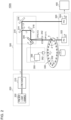
- Fig. 2 is a diagram illustrating an optical measurement apparatus 100A according to Embodiment 1.
- the optical measurement apparatus 100A has a light source apparatus 200, a spectroscopic head 300, and an arithmetic processing unit 400.
- the optical measurement apparatus 100A is directed to inspection of a product (sample 2) that is industrially mass-produced.
- the light source apparatus 200 generates the wavelength swept light L1 whose wavelength changes with time.
- the wavelength swept light L1 is featured by one-to-one correspondence between time and wavelength. This is expressed as the wavelength swept light L1 has "uniqueness of wavelength”.
- the light source apparatus 200 contains a pulsed light source 202 and a stretcher 210.
- the pulsed light source 202 emits broadband pulsed light L1a having a broadband continuous spectrum.
- the spectrum of the broadband pulsed light L1a is continuous typically within a wavelength range from 900 nm to 1300 nm, at least over a 10 nm range, preferably over a 50 nm range, and more preferably over a 100 nm range. Width of the wavelength range of the broadband pulsed light L1a may only be wide enough to cover a wavelength range necessary for the spectroscopy.
- Fig. 3 is a drawing illustrating the wavelength swept light L1.
- the upper tier of Fig. 3 illustrates intensity (time-axis waveform) I WS (t) of the wavelength swept light L1, and the lower tier illustrates a temporal change in wavelength ⁇ of the wavelength swept light L1.
- the wavelength swept light L1 in this example is given by a single pulse, having dominant wavelength ⁇ 1 at the leading edge, and dominant wavelength ⁇ n at the trailing edge, while demonstrating a temporal change in the wavelength between ⁇ 1 and ⁇ n within one pulse.
- the wavelength swept light L1 in this example is a positively chirped pulse ( ⁇ 1 > ⁇ n ) whose frequency increases with time, in other words, whose wavelength shortens with time.
- the wavelength swept light L1 may alternatively be a negatively chirped pulse whose wavelength becomes longer with time ( ⁇ 1 ⁇ ⁇ n ). As described later, the wavelength swept light L1 may be given by a pulse train that contains temporally isolated pulses (wave fluxes) for each wavelength.
- the spectroscopic head 300 contains an irradiation optical system 310, a light receiver 320, a conveyor 330, an optical path switching element 340, an aperture 342, and a controller 350.
- the irradiation optical system 310 receives the wavelength swept light L1 from the light source apparatus 200, and irradiates a measurement position where the target sample 2 to be measured should pass.
- the optical path switching element 340 in this embodiment is constituted as a part of the irradiation optical system 310, and the irradiation optical system 310 contains a beam splitter 314, mirrors 316, 318, and the optical path switching element 340.
- the irradiation optical system 310 may contain unillustrated mirror, lens, or the like.
- the optical path switching element 340 can be switched between a first state ⁇ 1 and a second state ⁇ 2, and can direct in the first state ⁇ 1 the wavelength swept light L1 to a first optical path OP1 laid through the measurement position 4, meanwhile can direct in the second state ⁇ 2 the light to a second optical path OP2 deviated from the first optical path OP1.
- a galvano mirror a micro electro-mechanical systems (MEMS) mirror, a polygon mirror, a piezo-driven mirror or the like, but not limited thereto.
- the aperture 342 is interposed between the optical path switching element 340 and the measurement position 4.
- the aperture 342 is an iris, a pinhole, a slit, a knife edge (single-edged slit) or the like, with which the first optical path OP1 is opened, meanwhile the light on the second optical path OP2 is shielded. Provision of the aperture 342 can prevent the wavelength swept light L1 from becoming stray light in the second state ⁇ 2.
- the light receiver 320 contains a first photodetector 322 and a second photodetector 324.
- the first photodetector 322 detects the object light L2 obtained by irradiating the wavelength swept light L1 onto the sample 2.
- the object light L2 in this embodiment is light ascribed to the wavelength swept light L1 transmitted through the sample 2.
- the second photodetector 324 detects the reference light L3. Output signals from the first photodetector 322 and the second photodetector 324 are respectively converted to digital signals D1 and D2 by an unillustrated A/D converter.
- a time-axis waveform I OBJ (t) of the object light L2 given by the digital signal D1, and a time-axis waveform I REF (t) of the reference light L3 given by the digital signal D2 are taken into an arithmetic processing unit 400.
- Fig. 4 is a drawing explaining spectroscopy with use of the optical measurement apparatus 100A illustrated in Fig. 2 . Since the wavelength swept light L1 is featured by the one-to-one correspondence between time t and wavelength ⁇ as described previously, so that the time-axis waveform I REF (t) may be converted to the spectrum I REF ( ⁇ ) in terms of frequency domain.
- the controller 350 monitors the conveyor 330, and determines presence or absence of the sample 2 in each sample holder 332.
- the controller 350 controls the optical path switching element 340, depending on presence or absence of the sample 2.
- the controller 350 contains a position sensor 352 and an arithmetic unit 356.
- the position sensor 352 is typically a rotary encoder, which detects the position (angle of rotation) of the conveyor 330.
- the arithmetic unit 356 preliminarily stores position information (load information) of the sample holder 332 not occupied by the sample 2.
- the load information is obtainable typically from a mounter that mounts the sample 2 on the sample holder 332, or from a host controller that controls the mounter. Alternatively, the load information may be manually entered by an operator who operates the optical measurement apparatus 100. Alternatively, in a case there is a preset inspection sequence by which a plurality of sample 2 are inspected in units (lots), wherein all sample holders 332 are occupied during the inspection for one lot, and will be vacant in an interval between the lots, absence of the sample 2 may be judged by the vacancy of the sample holders 332 in the interval between the lots.
- the arithmetic unit 356 compares the measurement value of the position sensor 352 with the load information that indicates the position of the sample holder 332 not occupied by the sample 2, and determines presence or absence of the sample at the measurement position 4.
- the arithmetic unit 356 controls the optical path switching element 340, according to the result of determination regarding presence or absence of the sample 2 at the measurement position 4.
- the arithmetic unit 356 keeps the optical path switching element 340 in the first state ⁇ 1, over a period the sample holder 332 occupied by the sample 2 passes through the measurement position 4. On the contrary, the arithmetic unit 356 switches the optical path switching element 340 to the second state ⁇ 2, over a period the sample holder 332 not occupied by the sample 2 passes through the measurement position 4.
- the optical path switching element 340 may be kept either in the first state ⁇ 1 or in the second state ⁇ 2, over a period the structure (disk) between the sample holders 332 passes through the measurement position 4. Basically, the sample holders 332 are more probable to have the sample 2 mounted thereon, whereas less probable to have no sample 2. Considering the service life of the optical path switching element 340, the optical path switching element 340 is preferably used while reducing the number of times of switching. The controller 350 therefore preferably keeps the optical path switching element 340 in the first state ⁇ 1, over a period the structure (disk) between the sample holders 332 passes through the measurement position 4.
- the optical path switching element 340 deviates the optical path of the wavelength swept light L1 from the normal optical path OP1, if the sample 2 is not present at the measurement position 4. This successfully prevents the high-power wavelength swept light L1, not attenuated by the sample 2, from being directly incident on the first photodetector 322, thereby protecting the first photodetector 322.
- the beam diameter of the wavelength swept light L1 in the wavelength swept light L1 was set to 0.8 mm (1/e 2 diameter).
- a slit with a 2 mm wide opening was used as the aperture 342.
- Retraction distance that is, the distance between the first optical path OP1 and the second optical path OP2 on the aperture 342 was set to 3 mm.
- Distance of retraction may be experimentally determined, in consideration of the damage threshold of the photodetector 322, the beam diameter, conveyance frequency, and performance (speed) of the optical path switching element 340.
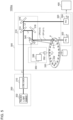
- Fig. 5 is a diagram illustrating an optical measurement apparatus 100Aa according to Modified Example 1.1.
- the aperture 342 illustrated in Fig. 2 is omitted.
- the second optical path OP2 over a period the optical path switching element 340 is kept in the second state ⁇ 2, is directed to a retreat position on the structure of the conveyor 330, while avoiding the areas of the sample holders 332.
- the other details are same as those illustrated in Fig. 2 .
- Fig. 6 is a diagram illustrating an optical measurement apparatus 100Ab according to Modified Example 1.2.
- the optical path switching element 340 illustrated in Fig. 2 was a part of the irradiation optical system 310, the optical path switching element 340 in this Modified Example 1.2 is positioned differently from that in Fig. 2 . More specifically, the optical path switching element 340 is arranged closer to the first photodetector 322 as viewed from the measurement position 4. The other details are same as those illustrated in Fig. 2 .
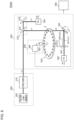
- Fig. 7 is a diagram illustrating an optical measurement apparatus 100Ac according to Modified Example 1.3.
- a conveyor 330c is structured differently from that in Fig. 2 .
- the conveyor 330c is similar to the conveyor 330 illustrated in Fig. 2 in that it has the rotating disk, but has no sample holder 332, instead having a vacuum suction mechanism that supports the sample 2 at any desired position on the circumference.
- the controller 350 compares the measurement value of the position sensor 352, with the position information of the sample holder not occupied by the sample, having been preliminarily stored in the arithmetic unit 356, and estimates whether the sample 2 is present or absent at the measurement position 4.
- the controller 350 switches the optical path switching element 340 to the first state ⁇ 1 over a period the sample 2 is present at the measurement position 4, meanwhile switches the optical path switching element 340 to the second state ⁇ 2 over a period the sample 2 is absent at the measurement position 4.
- the aperture 342 illustrated in Fig. 7 is omissible. Although the wavelength swept light L1 guided through the second optical path OP2 in this case can propagate without being blocked by the aperture 342, the purpose of protection of the first photodetector 322 may be fulfilled since the light is not incident on the first photodetector 322. The stray light, if anticipated, may be appropriately dealt with.
- the second optical path OP2 may be determined so as to be directed to the disk as illustrated in Fig. 5 .
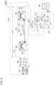
- Fig. 8 is a diagram illustrating an optical measurement apparatus 100Ad according to Modified Example 1.4.
- An optical path switching element 340d in this Modified Example 1.4 is arranged between the light source apparatus 200 and the spectroscopic head 300.
- optical path switching element 340d is connected to the output-side fiber 258.
- the optical path switching element 340d is a fiber switch, whose one output is connected to the spectroscopic head 300 through the first optical path OP1, meanwhile the other output is directed to the second optical path OP2.
- Fig. 8 illustrates an exemplary specific structure of the light source apparatus 200.
- the light source apparatus 200 has a pulsed light source 202, a wavelength selector 220, and a stretcher 210.
- the pulsed light source 202 emits broadband pulsed light L1a having a broadband continuous spectrum.
- the spectrum of the broadband pulsed light L1a is continuous typically within a wavelength range from 900 nm to 1300 nm, at least over a 10 nm range, preferably over a 50 nm range, and more preferably over a 100 nm range. Width of the wavelength range of the broadband pulsed light L1a may only be wide enough to cover a wavelength range necessary for the spectroscopy.
- the pulsed light source 202 may contain an ultrashort pulse laser and a nonlinear element.
- the ultrashort pulse laser is exemplified by gain-switched laser, microchip laser, and fiber laser.
- the nonlinear element further widens the spectral width of the ultrashort pulse generated by the ultrashort pulse laser, with the aid of a nonlinear phenomenon.
- the nonlinear element is preferably a fiber, to which photonic crystal fiber or other nonlinear fiber is applicable. Mode of the fiber, although preferably single mode, may alternatively be multimode so long as a sufficient level of nonlinearity may be demonstrated.
- the pulsed light source 202 usable herein may be other broadband pulsed light source, such as superluminescent diode (SLD).
- SLD superluminescent diode
- the broadband pulsed light L1a output from the nonlinear element has a pulse width in the order of femtoseconds to nanoseconds.
- the broadband pulsed light L1a generated by the pulsed light source 202 is once emitted to a free space.
- the wavelength selector 220 selects a wavelength band to be used for the measurement from the broadband pulsed light L1a, and cuts off any wavelength band not to be used.
- the wavelength selector 220 contains a lens 222, a wavelength selection filter 224, and a condenser lens 226.
- the lens 222 collimates the broadband pulsed light L1a.
- the wavelength selection filter 224 allows a wavelength band to be used for the measurement to transmit therethrough, and cuts off any wavelength band no to be used by reflection or absorption.
- the condenser lens 226 condenses the light transmitted through the wavelength selection filter 224 onto the input end of a divider 230.
- the stretcher 210 receives the broadband pulsed light L1a, and convert the light into the wavelength swept light L1.
- the stretcher 210 contains the divider 230, a delay line 240, and a coupler 250.
- the divider 230 contains an input-side fiber 238 and a first AWG 232.
- the first AWG 232 has an input waveguide 234, and a plurality n (n ⁇ 2) of output waveguides 236.
- the first AWG 232 receives the broadband pulsed light L1a through the input-side fiber 238.
- the light guided through the input waveguide 234 is branched into n lines of the output waveguides 236, according to the wavelength.
- the delay line 240 contains a plurality n of fibers 242_1 to 242_n.
- the fibers 242_1 to 242_n have different lengths, and give different levels of delay to the multiple beams divided by the divider 230.
- the broadband pulsed light L1a before being divided is given by a positive chirp pulse (up-chirp pulse) whose frequency increases (wavelength shortens) with time.
- the pulse in this case contains a component having the longest wavelength ⁇ 1 at the leading edge, and a component having the shortest wavelength ⁇ n at the trailing edge.
- the plurality of fibers 242_1 to 242_n have different lengths I 1 to I n .
- ⁇ 1 denote the longest wavelength
- ⁇ n denote the shortest wavelength
- the lengths I 1 to I 20 of the twenty fibers 242 may increase from 1 m to 20 m in one-meter increments.
- the fibers 242_1 to 242_n do not necessarily have group delay characteristics which differ for each wavelength, and may use the same fiber (having the same core/clad material).
- the fiber 242 usable herein may be a multi-mode fiber, which is advantageous in that any unintended nonlinear optical effect is avoidable.
- the coupler 250 recombines a plurality of beams having been differently delayed by the delay line 240.
- the coupler 250 typically contains a second AWG 252 and the output-side fiber 258.
- the second AWG 252 has n lines of input waveguides 254, and an output waveguide 256.
- the n lines of input waveguides 254 have the n fibers 242_1 to 242_n connected thereto.
- the second AWG 252 multiplexes n beams guided through the n lines of input waveguides 254, and outputs the resultant beam to the output waveguide 256.
- the input end of the output-side fiber 258 is connected to the output waveguide 256.
- the output-side fiber 258 extends to the spectroscopic head 300, and the output end of the output-side fiber 258 is connected to the spectroscopic head 300.
- the individual wave fluxes having the wavelengths ⁇ 1 to ⁇ n are temporally separated, thus converting the wavelength swept light L1 to a pulse train that contains n pulses corresponded to the wavelengths ⁇ 1 to ⁇ n .
- the spectroscopic head 300 contains the controller 350.
- the controller 350 compares the measurement value of the position sensor 352, with the position information of the sample holder not occupied by the sample, having been preliminarily stored in the arithmetic unit 356, to determine whether the sample 2 is present or absent, and controls the optical path switching element 340d with reference to the result of determination.
- Fig. 9 is a drawing illustrating an optical measurement apparatus 100B according to Embodiment 2.
- the optical measurement apparatus 100B contains a light shielding element 360, in place of the optical path switching element 340 illustrated in Fig. 2 .
- the light shielding element 360 is arranged on the optical path of the wavelength swept light L1, and is structured to be switchable between the first state ⁇ 1 and the second state ⁇ 2.
- the light shielding element 360 allows the wavelength swept light L1 to pass therethrough in the first state ⁇ 1 (transmission state), and shields the object light L2 in the second state ⁇ 2.
- Light shielding also includes dimming.
- variable attenuator is exemplified by liquid crystal shutter, acousto-optical modulator (AOM), and electro-optical modulator (EOM).
- the controller 350 controls the state of the light shielding element 360.
- the control by the controller 350 is similar to that in Embodiment 1.
- the light shielding element 360 shields the optical path of the wavelength swept light L1, if the sample 2 is absent at the measurement position 4. This successfully prevents the high-power wavelength swept light L1, not attenuated by the sample 2, from being directly incident on the first photodetector 322, thereby protecting the first photodetector 322.
- Fig. 10 is a diagram illustrating an optical measurement apparatus 100Ba according to Modified Example 2.1.
- the light shielding element 360 is arranged on the path of the wavelength swept light L1, closer to the first photodetector 322 as viewed from the measurement position 4.
- the conveyor 330c illustrated in Fig. 7 may be applied to Embodiment 2.
- the light shielding element 360 may be arranged between the light source apparatus 200 and the spectroscopic head 300, like in the case illustrated in Fig. 8 .
- the conveyor 330 is not limited to a disk-shaped one.
- a roller conveyor may be used for example.
Landscapes
- Physics & Mathematics (AREA)
- Spectroscopy & Molecular Physics (AREA)
- General Physics & Mathematics (AREA)
- Chemical & Material Sciences (AREA)
- Life Sciences & Earth Sciences (AREA)
- Analytical Chemistry (AREA)
- Biochemistry (AREA)
- General Health & Medical Sciences (AREA)
- Health & Medical Sciences (AREA)
- Immunology (AREA)
- Pathology (AREA)
- Optics & Photonics (AREA)
- Engineering & Computer Science (AREA)
- Textile Engineering (AREA)
- Investigating Or Analysing Materials By Optical Means (AREA)
- Spectrometry And Color Measurement (AREA)
Abstract
Description
- The present disclosure relates to an optical measurement apparatus.
- Wavelength swept-type spectroscopy is one known method for measuring optical characteristics. A wavelength swept-type spectrometer generates wavelength swept light whose wavelength changes with time, and irradiates a target object to be inspected with the wavelength swept light. The wavelength swept light is given by a pulse or a pulse train having one-to-one correspondence between time and wavelength. The wavelength swept light is irradiated onto the target object to be inspected, and a time-axis waveform of the resultant light is detected with a photodetector. An output waveform of the photodetector represents a spectrum whose time axis corresponds to wavelength.
- Spectroscopic analysis is classified into transmission type that handles transmitted light of a target object as the object light, and a reflection type that handles reflected light as the object light. The reflection type is suitable for measuring an object having a high reflectance. Optical information obtainable therefrom is, however, limited to those ascribable to the surface or around of the target object. The reflection type is, therefore, considered to be not accurate enough for measurement of the target object such as precise industrial product, specimen collected from plant/animal, substance ingested by human body, liquid or gas produced in production plant.
- The transmission type can obtain optical characteristics not only from the surface of the target object, but also from deep inside, and is therefore suitable for a case where the target object is food, beverage or the like (collectively referred to as food and drink, hereinafter).
Patent Literature 1 discloses a transmission-type product inspection apparatus. The product inspection apparatus has an irradiation optical system structured to irradiate a front face of a product (target object to be inspected) with pulsed light, and a photodetector arranged on the back side of the product, and is structured to receive light transmitted through the product. -
Fig. 1 is a diagram illustrating aspectrometer 10 of a wavelength swept-type. Thespectrometer 10 has alight source apparatus 20, aspectroscopic head 30, and anarithmetic processing unit 40. - The
light source apparatus 20 produces wavelength swept light L1. The wavelength swept light L1 is guided to thespectroscopic head 30. An irradiationoptical system 31 of thespectroscopic head 30 irradiates asample 2 with the wavelength swept light L1. Afirst photodetector 32 receives transmitted light (object light) L2 obtained as a result of irradiation of the wavelength swept light L1 onto thesample 2. - In the irradiation
optical system 31, a part of the wavelength swept light L1 is branched to yield a reference light L3. Asecond photodetector 33 measures the reference light L3. - A first detection signal S1 generated by the
first photodetector 32, and a second detection signal S2 generated by thesecond photodetector 33 are supplied to thearithmetic processing unit 40. The object light L2 and the reference light L3 take over the one-to-one time-wavelength correspondence of the wavelength swept light L1. The time-axis waveform of the first detection signal S1 may be converted to a spectrum of the object light L2, by converting the time axis to the wavelength. Similarly, the time-axis waveform of the second detection signal S2 may be converted to a spectrum of the reference light L3, by converting the time axis to the wavelength. Thearithmetic processing unit 40 calculates proportion of the object light L2 relative to the reference light L3 for each corresponding wavelength, and measures a spectral characteristic (reflectance) of thesample 2. - Patent Literature 1:
JP 2020-159973A - The present inventors examined the transmission-type spectrometer, to find the problems below.
- For a target product to be measured (also referred to as product, hereinafter) having low light transmittance and high diffusivity, the photodetector is designed and selected while being adapted to low power of incident light. Meanwhile, the light source apparatus used therefor is a pulse laser having high peak power, so as to increase power of the transmitted light.
- Industrially mass-produced products, when inspected, are automatically conveyed on a conveyor at high speed, which are anticipated to fall off from the conveyor, or to cause displacement. This would result in an event such that the product is absent at a measurement position such that the product should be present. In this event, the wavelength swept light L1, which is a pulsed laser beam irradiated on the measurement position, will be directly incident on the photodetector, without passing through the product.
- Since the photodetector is designed and selected while being adapted to low power of the incident light as described previously, so that the direct incidence of the laser beam having a high peak power would exceed an allowable power of the photodetector, and would degrade the reliability.
- Some product conveyors may convey the products while keeping a gap in between. The laser beam in this case would be incident on the photodetector through the gap.
- In particular, an element having a built-in amplification mechanism such as avalanche photodiode, is known to have a low damage threshold. For example, an InGaAs avalanche photodetector APD430C from THORLABS, USA has a damage threshold of 1 mW. The power of the laser in the present spectroscopic method is sufficiently larger than the threshold.
- The present disclosure has been arrived at considering such circumstances, wherein one of exemplary objects of a certain mode of the disclosure is to provide an optical measurement apparatus capable of protecting the photodetector.
- An optical measurement apparatus of the present disclosure includes:
- a light source apparatus structured to generate wavelength swept light;
- an irradiation optical system structured to irradiate a measurement position with the wavelength swept light;
- a conveyor structured to convey a target object to be measured so as to pass it through the measurement position;
- a light receiver structured to measure an object light ascribed to the wavelength swept light transmitted through the target object to be measured;
- an optical path switching element provided to an optical path of the wavelength swept light, and is structured to switch the optical path of the wavelength swept light; and
- a controller structured to control the optical path switching element, depending on presence or absence of the target object to be measured.
- Also another aspect of the present disclosure relates to an optical measurement apparatus. The optical measurement apparatus includes:
- a light source apparatus structured to generate wavelength swept light;
- an irradiation optical system structured to irradiate a measurement position with the wavelength swept light;
- a conveyor structured to convey a target object to be measured so as to pass it through the measurement position;
- a light receiver structured to measure an object light ascribed to the wavelength swept light transmitted through the target object to be measured;
- a light shielding element provided to an optical path of the wavelength swept light, and is structured to switch between transmission/non-transmission of the wavelength swept light; and
- a controller structured to control the light shielding element, depending on presence or absence of the target object to be measured.
- Note that also free combinations of these constituents, and also any of the constituents and expressions exchanged among the method, apparatus, and system, are valid as the modes of the present disclosure. Also note that the description of this section (SOLUTION TO PROBLEM) does not describe all essential features of the invention, and thus also subcombinations of these features described may constitute the invention.
- One aspect of the present disclosure can protect the photodetector.
-
- [
Fig. 1] Fig. 1 is a diagram illustrating a wavelength swept-type spectrometer. - [
Fig. 2] Fig. 2 is a diagram illustrating an optical measurement apparatus according toEmbodiment 1. - [
Fig. 3] Fig. 3 is a drawing illustrating wavelength swept light. - [
Fig. 4] Fig. 4 is a drawing explaining spectroscopy with use of the optical measurement apparatus illustrated inFig. 2 . - [
Fig. 5] Fig. 5 is a diagram illustrating an optical measurement apparatus according to Modified Example 1.1. - [
Fig. 6] Fig. 6 is a diagram illustrating an optical measurement apparatus according to Modified Example 1.2. - [
Fig. 7] Fig. 7 is a diagram illustrating an optical measurement apparatus according to Modified Example 1.3. - [
Fig. 8] Fig. 8 is a diagram illustrating an optical measurement apparatus according to Modified Example 1.4. - [
Fig. 9] Fig. 9 is a drawing illustrating an optical measurement apparatus according toEmbodiment 2. - [
Fig. 10] Fig. 10 is a diagram illustrating an optical measurement apparatus according to Modified Example 2.1. - Some exemplary embodiments of the present disclosure will be outlined. This outline will provide introduction into the detailed description that follows, and will brief some concepts of one or more embodiments for basic understanding thereof, without limiting the scope of the invention or disclosure. Also note this summary is not a comprehensive overview of all possible embodiments, and thus does not limit the essential components of the embodiments. For convenience, the term "one embodiment" may be used to designate a single embodiment (Example or Modified Example), or a plurality of embodiments (Examples or Modified Examples) disclosed in the present specification.
- The optical measurement apparatus according to one embodiment includes:
- a light source apparatus structured to generate wavelength swept light;
- an irradiation optical system structured to irradiate a measurement position with the wavelength swept light;
- a conveyor structured to convey a target object to be measured so as to pass it through the measurement position;
- a light receiver structured to measure an object light ascribed to the wavelength swept light transmitted through the target object to be measured;
- an optical path switching element provided to an optical path of the wavelength swept light, and is structured to switch the optical path of the wavelength swept light; and
- a controller structured to control the optical path switching element, depending on presence or absence of the target object to be measured.
- The optical measurement apparatus according to one embodiment includes:
- a light source apparatus structured to generate wavelength swept light;
- an irradiation optical system structured to irradiate a measurement position with the wavelength swept light;
- a conveyor structured to convey a target object to be measured so as to pass it through the measurement position;
- a light receiver structured to measure an object light ascribed to the wavelength swept light transmitted through the target object to be measured;
- a light shielding element provided to an optical path of the wavelength swept light, and is structured to switch between transmission/non-transmission of the wavelength swept light; and
- a controller structured to control the light shielding element, depending on presence or absence of the target object to be measured.
- These apparatuses, structured to monitor presence or absence of the target object to be measured, can detect an event where the measurement target is absent on the optical path of the wavelength swept light emitted from the light source apparatus towards the photodetector of the light receiver, in other words, an event where the wavelength swept light can be directly incident on the photodetector. Upon detection of such event, these apparatuses can deviate the optical path of the wavelength swept light from the normal optical path directed to the photodetector, or can enable the light shielding element, thereby successfully preventing the wavelength swept light from being directly incident on the photodetector.
- In one embodiment, the optical path switching element may contain any one of a galvano mirror, a micro electro mechanical systems (MEMS) mirror, a piezo-driven mirror, a polygon mirror, or a fiber switch.
- In one embodiment, the optical measurement apparatus may further contain an aperture provided on the output end side of the optical path switching element. In this structure, the light deviated from the normal optical path is shielded by the aperture, and can therefore be prevented from becoming stray light in the optical measurement apparatuses.
- In one embodiment, the aperture may be a pinhole, a slit, or a knife edge.
- In one embodiment, the light shielding element may contain either a movable shutter or a variable attenuator. In one embodiment, the variable attenuator may contain any of a liquid crystal shutter, an acousto-optical modulator, or an electro-optical modulator. The light shielding element does not need to completely shield the wavelength swept light, and may only be able to reduce the amount of light down to or below the damage threshold of the photodetector.
- The present disclosure will be explained below on the basis of preferred embodiments, referring to the attached drawings. All constituents, members and processes illustrated in the individual drawings will be given same reference numerals, so as to properly avoid redundant explanations. The embodiments are merely illustrative, and are not restrictive about the disclosure. All features and combinations thereof described in the embodiments are not always essential to the disclosure.
- Dimensions (thickness, length, width, etc.) of the individual members illustrated in the drawings may be appropriately enlarged or shrunk for easy understanding. Furthermore, the dimensions of the plurality of members do not necessarily indicate the dimensional relationship among them, so that a certain member A, if depicted thicker than another member B in a drawing, may even be thinner than the member B.
-
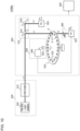
Fig. 2 is a diagram illustrating anoptical measurement apparatus 100A according toEmbodiment 1. Theoptical measurement apparatus 100A has alight source apparatus 200, aspectroscopic head 300, and anarithmetic processing unit 400. Theoptical measurement apparatus 100A is directed to inspection of a product (sample 2) that is industrially mass-produced. - The
light source apparatus 200 generates the wavelength swept light L1 whose wavelength changes with time. The wavelength swept light L1 is featured by one-to-one correspondence between time and wavelength. This is expressed as the wavelength swept light L1 has "uniqueness of wavelength". - The
light source apparatus 200 contains a pulsedlight source 202 and astretcher 210. The pulsedlight source 202 emits broadband pulsed light L1a having a broadband continuous spectrum. The spectrum of the broadband pulsed light L1a is continuous typically within a wavelength range from 900 nm to 1300 nm, at least over a 10 nm range, preferably over a 50 nm range, and more preferably over a 100 nm range. Width of the wavelength range of the broadband pulsed light L1a may only be wide enough to cover a wavelength range necessary for the spectroscopy. - The
stretcher 210 stretches the broadband pulsed light L1a emitted from the pulsedlight source 202 on the time axis, to generate the wavelength swept light L1. -
Fig. 3 is a drawing illustrating the wavelength swept light L1. The upper tier ofFig. 3 illustrates intensity (time-axis waveform) IWS(t) of the wavelength swept light L1, and the lower tier illustrates a temporal change in wavelength λ of the wavelength swept light L1. The wavelength swept light L1 in this example is given by a single pulse, having dominant wavelength λ1 at the leading edge, and dominant wavelength λn at the trailing edge, while demonstrating a temporal change in the wavelength between λ1 and λn within one pulse. The wavelength swept light L1 in this example is a positively chirped pulse (λ1 > λn) whose frequency increases with time, in other words, whose wavelength shortens with time. Note that the wavelength swept light L1 may alternatively be a negatively chirped pulse whose wavelength becomes longer with time (λ1 < λn). As described later, the wavelength swept light L1 may be given by a pulse train that contains temporally isolated pulses (wave fluxes) for each wavelength. - Referring now back to
Fig. 2 . Thespectroscopic head 300 contains an irradiationoptical system 310, alight receiver 320, aconveyor 330, an opticalpath switching element 340, anaperture 342, and acontroller 350. - The irradiation
optical system 310 receives the wavelength swept light L1 from thelight source apparatus 200, and irradiates a measurement position where thetarget sample 2 to be measured should pass. The opticalpath switching element 340 in this embodiment is constituted as a part of the irradiationoptical system 310, and the irradiationoptical system 310 contains abeam splitter 314, mirrors 316, 318, and the opticalpath switching element 340. The irradiationoptical system 310 may contain unillustrated mirror, lens, or the like. - The
beam splitter 314 splits the wavelength swept light L1 into two beams. One beam is a measurement light to be irradiated on thesample 2, and the other beam is the reference light L3. Themirror 318 directs the measurement light to the opticalpath switching element 340. - The optical
path switching element 340 can be switched between a first state ϕ1 and a second state ϕ2, and can direct in the first state ϕ1 the wavelength swept light L1 to a first optical path OP1 laid through themeasurement position 4, meanwhile can direct in the second state ϕ2 the light to a second optical path OP2 deviated from the first optical path OP1. For the opticalpath switching element 340, usable is a galvano mirror, a micro electro-mechanical systems (MEMS) mirror, a polygon mirror, a piezo-driven mirror or the like, but not limited thereto. - The
aperture 342 is interposed between the opticalpath switching element 340 and themeasurement position 4. Theaperture 342 is an iris, a pinhole, a slit, a knife edge (single-edged slit) or the like, with which the first optical path OP1 is opened, meanwhile the light on the second optical path OP2 is shielded. Provision of theaperture 342 can prevent the wavelength swept light L1 from becoming stray light in the second state ϕ2. - The irradiation
optical system 310 may further contain, in a preceding stage of thebeam splitter 314, a collimator that collimates the wavelength swept light L1 emitted from thelight source apparatus 200. - The
conveyor 330 conveys thetarget sample 2 to be measured so as to pass it through themeasurement position 4. Structure and shape of theconveyor 330 are not particularly limited. Theconveyor 330 in this embodiment is of a disc-rotating type, with a plurality ofsample holders 332 arranged in the periphery of the disc. An unillustrated mounter sequentially mounts thesample 2 before inspection on thesample holders 332, and sequentially takes out the inspectedsample 2. During a normal operation of theconveyor 330 and the mounter, thesample 2 is mounted on all thesample holders 332. - The
light receiver 320 contains afirst photodetector 322 and asecond photodetector 324. Thefirst photodetector 322 detects the object light L2 obtained by irradiating the wavelength swept light L1 onto thesample 2. The object light L2 in this embodiment is light ascribed to the wavelength swept light L1 transmitted through thesample 2. Thesecond photodetector 324 detects the reference light L3. Output signals from thefirst photodetector 322 and thesecond photodetector 324 are respectively converted to digital signals D1 and D2 by an unillustrated A/D converter. - A time-axis waveform IOBJ(t) of the object light L2 given by the digital signal D1, and a time-axis waveform IREF(t) of the reference light L3 given by the digital signal D2 are taken into an
arithmetic processing unit 400. - In the wavelength swept-type spectroscopy, the wavelength swept light L1 is featured by the one-to-one correspondence between time and wavelength. This correspondence is of course owned by the reference light L3, and also inherited by the object light L2. With use of such correspondence between time and wavelength, the
arithmetic processing unit 400 converts the time-axis waveform IOBJ(t) of the object light L2 into a spectrum IOBJ(λ) in terms of frequency domain. Thearithmetic processing unit 400 also converts the time-axis waveform IREF(t) of the reference light L3 into a spectrum, followed by appropriate scaling, to calculate a reference spectrum IREF(λ). - The processing by the
arithmetic processing unit 400 is not particularly limited. For example, thearithmetic processing unit 400 can calculate transmittance T(λ) of an object OBJ, from the reference spectrum IREF(A) and the spectrum IOBJ(λ) of the object light L2.
-
Fig. 4 is a drawing explaining spectroscopy with use of theoptical measurement apparatus 100A illustrated inFig. 2 . Since the wavelength swept light L1 is featured by the one-to-one correspondence between time t and wavelength λ as described previously, so that the time-axis waveform IREF(t) may be converted to the spectrum IREF(λ) in terms of frequency domain. - Also the time-axis waveform IOBJ(t) of the object light L2 will have the one-to-one correspondence between time t and wavelength A. The
arithmetic processing unit 400 can therefore convert the waveform IOBJ(t) of the object light L2 given by the output of thelight receiver 320, into the spectrum IOBJ(λ) of the object light L2. - The
arithmetic processing unit 400 can calculate transmission spectrum T(λ) of the object OBJ, from IOBJ(λ)/IREF(λ), which is a ratio of two spectra IOBJ(λ) and IREF(λ). - Given that a relation between time t and wavelength λ regarding the wavelength swept light L1 is expressed by a function λ = f(t). Most simply, the wavelength λ varies linearly with time t, according to a linear function. Lowering of the time-axis waveform IOBJ(t) of the object light L2 at a certain point in time tx means that the transmission spectrum T(λ) has an absorption spectrum at wavelength λx = f(tx).
- Note that the processing by the
arithmetic processing unit 400 is not limited thereto. The transmission spectrum T(λ) may alternatively be calculated by calculating T(t) = IOBJ(t)/IREF(t), which is a ratio of two time-axis waveforms IOBJ(t) and IREF(t), and then by converting the variable t of the time-axis waveform T(t) into A. - Referring now back to
Fig. 2 . Thecontroller 350 monitors theconveyor 330, and determines presence or absence of thesample 2 in eachsample holder 332. Thecontroller 350 controls the opticalpath switching element 340, depending on presence or absence of thesample 2. - For example, the
controller 350 contains aposition sensor 352 and anarithmetic unit 356. Theposition sensor 352 is typically a rotary encoder, which detects the position (angle of rotation) of theconveyor 330. - The
arithmetic unit 356 preliminarily stores position information (load information) of thesample holder 332 not occupied by thesample 2. The load information is obtainable typically from a mounter that mounts thesample 2 on thesample holder 332, or from a host controller that controls the mounter. Alternatively, the load information may be manually entered by an operator who operates the optical measurement apparatus 100. Alternatively, in a case there is a preset inspection sequence by which a plurality ofsample 2 are inspected in units (lots), wherein allsample holders 332 are occupied during the inspection for one lot, and will be vacant in an interval between the lots, absence of thesample 2 may be judged by the vacancy of thesample holders 332 in the interval between the lots. Thearithmetic unit 356 compares the measurement value of theposition sensor 352 with the load information that indicates the position of thesample holder 332 not occupied by thesample 2, and determines presence or absence of the sample at themeasurement position 4. - The
arithmetic unit 356 controls the opticalpath switching element 340, according to the result of determination regarding presence or absence of thesample 2 at themeasurement position 4. - The
arithmetic unit 356 keeps the opticalpath switching element 340 in the first state ϕ1, over a period thesample holder 332 occupied by thesample 2 passes through themeasurement position 4. On the contrary, thearithmetic unit 356 switches the opticalpath switching element 340 to the second state ϕ2, over a period thesample holder 332 not occupied by thesample 2 passes through themeasurement position 4. - The optical
path switching element 340 may be kept either in the first state ϕ1 or in the second state ϕ2, over a period the structure (disk) between thesample holders 332 passes through themeasurement position 4. Basically, thesample holders 332 are more probable to have thesample 2 mounted thereon, whereas less probable to have nosample 2. Considering the service life of the opticalpath switching element 340, the opticalpath switching element 340 is preferably used while reducing the number of times of switching. Thecontroller 350 therefore preferably keeps the opticalpath switching element 340 in the first state ϕ1, over a period the structure (disk) between thesample holders 332 passes through themeasurement position 4. - The basic structure and operations of the
optical measurement apparatus 100A have been described. - In the
optical measurement apparatus 100A, the opticalpath switching element 340 deviates the optical path of the wavelength swept light L1 from the normal optical path OP1, if thesample 2 is not present at themeasurement position 4. This successfully prevents the high-power wavelength swept light L1, not attenuated by thesample 2, from being directly incident on thefirst photodetector 322, thereby protecting thefirst photodetector 322. - Experiments were run to verify the effect of the
optical measurement apparatus 100A. The beam diameter of the wavelength swept light L1 in the wavelength swept light L1 was set to 0.8 mm (1/e2 diameter). A slit with a 2 mm wide opening was used as theaperture 342. Retraction distance, that is, the distance between the first optical path OP1 and the second optical path OP2 on theaperture 342 was set to 3 mm. - Intensity of light incident on the
first photodetector 322, through thesample holder 332 not occupied by thesample 2, was measured for each of the first state ϕ1 and the second state ϕ2. Intensity of incidence on thefirst photodetector 322 was found to be 58 mW in the first state ϕ1, whereas 12 µW in the second state ϕ2, proving reduction down to 0.021%. This level is sufficiently lower than an allowable input (damage threshold) of thefirst photodetector 322. - Distance of retraction may be experimentally determined, in consideration of the damage threshold of the
photodetector 322, the beam diameter, conveyance frequency, and performance (speed) of the opticalpath switching element 340. - Next, Modified Examples derived from
Embodiment 1 will be described. -
Fig. 5 is a diagram illustrating an optical measurement apparatus 100Aa according to Modified Example 1.1. In this Modified Example, theaperture 342 illustrated inFig. 2 is omitted. The second optical path OP2, over a period the opticalpath switching element 340 is kept in the second state ϕ2, is directed to a retreat position on the structure of theconveyor 330, while avoiding the areas of thesample holders 332. The other details are same as those illustrated inFig. 2 . -
Fig. 6 is a diagram illustrating an optical measurement apparatus 100Ab according to Modified Example 1.2. Although the opticalpath switching element 340 illustrated inFig. 2 was a part of the irradiationoptical system 310, the opticalpath switching element 340 in this Modified Example 1.2 is positioned differently from that inFig. 2 . More specifically, the opticalpath switching element 340 is arranged closer to thefirst photodetector 322 as viewed from themeasurement position 4. The other details are same as those illustrated inFig. 2 . -
Fig. 7 is a diagram illustrating an optical measurement apparatus 100Ac according to Modified Example 1.3. In this Modified Example 1.3, aconveyor 330c is structured differently from that inFig. 2 . Theconveyor 330c is similar to theconveyor 330 illustrated inFig. 2 in that it has the rotating disk, but has nosample holder 332, instead having a vacuum suction mechanism that supports thesample 2 at any desired position on the circumference. - The
controller 350 compares the measurement value of theposition sensor 352, with the position information of the sample holder not occupied by the sample, having been preliminarily stored in thearithmetic unit 356, and estimates whether thesample 2 is present or absent at themeasurement position 4. Thecontroller 350 switches the opticalpath switching element 340 to the first state ϕ1 over a period thesample 2 is present at themeasurement position 4, meanwhile switches the opticalpath switching element 340 to the second state ϕ2 over a period thesample 2 is absent at themeasurement position 4. - The
aperture 342 illustrated inFig. 7 is omissible. Although the wavelength swept light L1 guided through the second optical path OP2 in this case can propagate without being blocked by theaperture 342, the purpose of protection of thefirst photodetector 322 may be fulfilled since the light is not incident on thefirst photodetector 322. The stray light, if anticipated, may be appropriately dealt with. - Alternatively, in a case where the
aperture 342 illustrated inFig. 7 is omitted, the second optical path OP2 may be determined so as to be directed to the disk as illustrated inFig. 5 . -
Fig. 8 is a diagram illustrating an optical measurement apparatus 100Ad according to Modified Example 1.4. An opticalpath switching element 340d in this Modified Example 1.4 is arranged between thelight source apparatus 200 and thespectroscopic head 300. - For example, they are coupled by an optical fiber (output-side fiber) 258, and the optical
path switching element 340d is connected to the output-side fiber 258. The opticalpath switching element 340d is a fiber switch, whose one output is connected to thespectroscopic head 300 through the first optical path OP1, meanwhile the other output is directed to the second optical path OP2. -
Fig. 8 illustrates an exemplary specific structure of thelight source apparatus 200. Thelight source apparatus 200 has a pulsedlight source 202, awavelength selector 220, and astretcher 210. - The pulsed
light source 202 emits broadband pulsed light L1a having a broadband continuous spectrum. The spectrum of the broadband pulsed light L1a is continuous typically within a wavelength range from 900 nm to 1300 nm, at least over a 10 nm range, preferably over a 50 nm range, and more preferably over a 100 nm range. Width of the wavelength range of the broadband pulsed light L1a may only be wide enough to cover a wavelength range necessary for the spectroscopy. - For example, the pulsed
light source 202 may contain an ultrashort pulse laser and a nonlinear element. The ultrashort pulse laser is exemplified by gain-switched laser, microchip laser, and fiber laser. - The nonlinear element further widens the spectral width of the ultrashort pulse generated by the ultrashort pulse laser, with the aid of a nonlinear phenomenon. The nonlinear element is preferably a fiber, to which photonic crystal fiber or other nonlinear fiber is applicable. Mode of the fiber, although preferably single mode, may alternatively be multimode so long as a sufficient level of nonlinearity may be demonstrated.
- The pulsed
light source 202 usable herein may be other broadband pulsed light source, such as superluminescent diode (SLD). - The broadband pulsed light L1a output from the nonlinear element has a pulse width in the order of femtoseconds to nanoseconds.
- The broadband pulsed light L1a generated by the pulsed
light source 202 is once emitted to a free space. - The
wavelength selector 220 selects a wavelength band to be used for the measurement from the broadband pulsed light L1a, and cuts off any wavelength band not to be used. For example, thewavelength selector 220 contains alens 222, awavelength selection filter 224, and acondenser lens 226. - The
lens 222 collimates the broadband pulsed light L1a. Thewavelength selection filter 224 allows a wavelength band to be used for the measurement to transmit therethrough, and cuts off any wavelength band no to be used by reflection or absorption. Thecondenser lens 226 condenses the light transmitted through thewavelength selection filter 224 onto the input end of adivider 230. - The
stretcher 210 receives the broadband pulsed light L1a, and convert the light into the wavelength swept light L1. Thestretcher 210 contains thedivider 230, adelay line 240, and acoupler 250. - The
divider 230 contains an input-side fiber 238 and afirst AWG 232. Thefirst AWG 232 has aninput waveguide 234, and a plurality n (n ≥ 2) ofoutput waveguides 236. Thefirst AWG 232 receives the broadband pulsed light L1a through the input-side fiber 238. The light guided through theinput waveguide 234 is branched into n lines of theoutput waveguides 236, according to the wavelength. - The
delay line 240 contains a plurality n of fibers 242_1 to 242_n. The fibers 242_1 to 242_n have different lengths, and give different levels of delay to the multiple beams divided by thedivider 230. - Assuming now the broadband pulsed light L1a before being divided is given by a positive chirp pulse (up-chirp pulse) whose frequency increases (wavelength shortens) with time. The pulse in this case contains a component having the longest wavelength λ1 at the leading edge, and a component having the shortest wavelength λn at the trailing edge.
- The plurality of fibers 242_1 to 242_n have different lengths I1 to In. Let λ1 denote the longest wavelength, and let λn denote the shortest wavelength, it suffices to fulfill a relation of 11 < I2 <... < In, in order to give the wavelength swept light L1 as a positive chirp pulse like the broadband pulsed light L1a. In an exemplary case with n = 20, the lengths I1 to I20 of the twenty fibers 242 may increase from 1 m to 20 m in one-meter increments.
- The fibers 242_1 to 242_n do not necessarily have group delay characteristics which differ for each wavelength, and may use the same fiber (having the same core/clad material). In this context, the fiber 242 usable herein may be a multi-mode fiber, which is advantageous in that any unintended nonlinear optical effect is avoidable.
- The
coupler 250 recombines a plurality of beams having been differently delayed by thedelay line 240. Thecoupler 250 typically contains a second AWG 252 and the output-side fiber 258. The second AWG 252 has n lines ofinput waveguides 254, and an output waveguide 256. - The n lines of
input waveguides 254 have the n fibers 242_1 to 242_n connected thereto. The second AWG 252 multiplexes n beams guided through the n lines ofinput waveguides 254, and outputs the resultant beam to the output waveguide 256. The input end of the output-side fiber 258 is connected to the output waveguide 256. - The output-
side fiber 258 extends to thespectroscopic head 300, and the output end of the output-side fiber 258 is connected to thespectroscopic head 300. - With sufficiently large delays given by the fibers 242, the individual wave fluxes having the wavelengths λ1 to λn are temporally separated, thus converting the wavelength swept light L1 to a pulse train that contains n pulses corresponded to the wavelengths λ1 to λn.
- The
spectroscopic head 300 contains thecontroller 350. Thecontroller 350 compares the measurement value of theposition sensor 352, with the position information of the sample holder not occupied by the sample, having been preliminarily stored in thearithmetic unit 356, to determine whether thesample 2 is present or absent, and controls the opticalpath switching element 340d with reference to the result of determination. -
Fig. 9 is a drawing illustrating anoptical measurement apparatus 100B according toEmbodiment 2. Theoptical measurement apparatus 100B contains alight shielding element 360, in place of the opticalpath switching element 340 illustrated inFig. 2 . - The
light shielding element 360 is arranged on the optical path of the wavelength swept light L1, and is structured to be switchable between the first state ϕ1 and the second state ϕ2. Thelight shielding element 360 allows the wavelength swept light L1 to pass therethrough in the first state ϕ1 (transmission state), and shields the object light L2 in the second state ϕ2. Light shielding also includes dimming. - For the
light shielding element 360, either a movable shutter or a variable attenuator is applicable. The variable attenuator is exemplified by liquid crystal shutter, acousto-optical modulator (AOM), and electro-optical modulator (EOM). - The
controller 350 controls the state of thelight shielding element 360. The control by thecontroller 350 is similar to that inEmbodiment 1. - In the
optical measurement apparatus 100B according toEmbodiment 2, thelight shielding element 360 shields the optical path of the wavelength swept light L1, if thesample 2 is absent at themeasurement position 4. This successfully prevents the high-power wavelength swept light L1, not attenuated by thesample 2, from being directly incident on thefirst photodetector 322, thereby protecting thefirst photodetector 322. - Next, Modified Examples derived from
Embodiment 2 will be described. -
Fig. 10 is a diagram illustrating an optical measurement apparatus 100Ba according to Modified Example 2.1. In Modified Example 2.1, thelight shielding element 360 is arranged on the path of the wavelength swept light L1, closer to thefirst photodetector 322 as viewed from themeasurement position 4. - The
conveyor 330c illustrated inFig. 7 may be applied toEmbodiment 2. - In
Embodiment 2, thelight shielding element 360 may be arranged between thelight source apparatus 200 and thespectroscopic head 300, like in the case illustrated inFig. 8 . - Lastly, a modified example relevant to both the
Embodiment 1 andEmbodiment 2 will be explained. - The
conveyor 330 is not limited to a disk-shaped one. A roller conveyor may be used for example. - Having described the embodiments according to the present disclosure with use of specific terms, the description is merely illustrative for better understanding, and by no means limits the disclosure or the claims. The scope of the present invention is defined by the claims, and therefore encompasses any embodiment, Example, and Modified Example having not been described above.
- L1 wavelength swept light, L1a broadband pulsed light, L2 object light, 2 sample, 4 measurement position, L3 reference light, 100 optical measurement apparatus, 200 light source apparatus, 202 pulsed light source, 210 stretcher, 220 wavelength selector, 222 lens, 224 wavelength selection filter, 226 condenser lens, 230 divider, 232 first AWG, 234 input waveguide, 236 output waveguide, 238 input-side fiber, 240 delay line, 242 fiber, 250 coupler, 252 second AWG, 254 input waveguide, 256 output waveguide, 258 output-side fiber, 300 spectroscopic head, 310 irradiation optical system, 312 collimator, 314 beam splitter, 316 mirror, 320 light receiver, 322 first photodetector, 324 second photodetector, 330 conveyor, 332 sample holder, 340 optical path switching element, 342 aperture, 350 controller, 352 position sensor, 356 arithmetic unit, 360 light shielding element, 400 arithmetic processing unit
Claims (6)
- An optical measurement apparatus comprising:a light source apparatus structured to generate wavelength swept light;an irradiation optical system structured to irradiate a measurement position with the wavelength swept light;a conveyor structured to convey a target object to be measured so as to pass the object through the measurement position;a light receiver structured to measure an object light ascribed to the wavelength swept light transmitted through the target object to be measured;an optical path switching element provided to an optical path of the wavelength swept light, and is structured to switch the optical path of the wavelength swept light; anda controller structured to control the optical path switching element, depending on presence or absence of the target object to be measured.
- The optical measurement apparatus according to claim 1, wherein the optical path switching element contains any one of a galvano mirror, a micro electro-mechanical systems (MEMS) mirror, a piezo-driven mirror, a polygon mirror, or a fiber switch.
- The optical measurement apparatus according to claim 2, further comprising an aperture provided on an output end side of the optical path switching element.
- An optical measurement apparatus comprising:a light source apparatus structured to generate wavelength swept light;an irradiation optical system structured to irradiate a measurement position with the wavelength swept light;a conveyor structured to convey a target object to be measured so as to pass the object through the measurement position;a light receiver structured to measure an object light ascribed to the wavelength swept light transmitted through the target object to be measured;a light shielding element provided to an optical path of the wavelength swept light, and is structured to switch between transmission/non-transmission of the wavelength swept light; anda controller structured to control the light shielding element, depending on presence or absence of the target object to be measured.
- The optical measurement apparatus according to claim 4, wherein the light shielding element contains either a movable shutter or a variable attenuator.
- The optical measurement apparatus according to claim 5, wherein the variable attenuator contains any of a liquid crystal shutter, an acousto-optical modulator, or an electro-optical modulator.
Applications Claiming Priority (2)
| Application Number | Priority Date | Filing Date | Title |
|---|---|---|---|
| JP2022092376A JP2023179208A (en) | 2022-06-07 | 2022-06-07 | light measurement device |
| PCT/JP2023/019148 WO2023238654A1 (en) | 2022-06-07 | 2023-05-23 | Optical measurement device |
Publications (2)
| Publication Number | Publication Date |
|---|---|
| EP4521082A1 true EP4521082A1 (en) | 2025-03-12 |
| EP4521082A4 EP4521082A4 (en) | 2026-04-29 |
Family
ID=89118187
Family Applications (1)
| Application Number | Title | Priority Date | Filing Date |
|---|---|---|---|
| EP23819638.0A Pending EP4521082A4 (en) | 2022-06-07 | 2023-05-23 | OPTICAL MEASURING DEVICE |
Country Status (6)
| Country | Link |
|---|---|
| US (1) | US20250354916A1 (en) |
| EP (1) | EP4521082A4 (en) |
| JP (1) | JP2023179208A (en) |
| KR (1) | KR20240161191A (en) |
| CN (1) | CN119072614A (en) |
| WO (1) | WO2023238654A1 (en) |
Families Citing this family (1)
| Publication number | Priority date | Publication date | Assignee | Title |
|---|---|---|---|---|
| JP2025017664A (en) * | 2023-07-25 | 2025-02-06 | 第一実業ビスウィル株式会社 | Light Measuring Device |
Family Cites Families (19)
| Publication number | Priority date | Publication date | Assignee | Title |
|---|---|---|---|---|
| JPS6295448A (en) * | 1985-10-23 | 1987-05-01 | Kowa Co | Method and device for measuring particle |
| JPH0979978A (en) * | 1995-09-11 | 1997-03-28 | Ishikawajima Harima Heavy Ind Co Ltd | Non-destructive component measuring device for vegetables |
| JP2782331B2 (en) * | 1995-09-12 | 1998-07-30 | 東洋農機株式会社 | Root vegetable detection device |
| US5995867A (en) * | 1997-03-19 | 1999-11-30 | Lucid Inc | Cellular surgery utilizing confocal microscopy |
| JPH1151928A (en) * | 1997-08-06 | 1999-02-26 | Kubota Corp | Fruit and vegetable quality measuring device |
| US6876392B1 (en) * | 1998-12-22 | 2005-04-05 | Matsushita Electric Industrial Co., Ltd. | Rangefinder for obtaining information from a three-dimensional object |
| KR100691924B1 (en) * | 1999-04-27 | 2007-03-09 | 지에스아이 루모닉스 인코퍼레이티드 | Material processing apparatus and method |
| JP2002039940A (en) * | 2000-07-21 | 2002-02-06 | Techno Ishii:Kk | Method and apparatus for detecting hollowing of object to be detected |
| JP2004089397A (en) * | 2002-08-30 | 2004-03-25 | Nidek Co Ltd | Laser therapy equipment |
| JP3923011B2 (en) * | 2002-12-24 | 2007-05-30 | 株式会社クボタ | Fruit and vegetable quality evaluation equipment |
| US7409117B2 (en) * | 2004-02-11 | 2008-08-05 | American Air Liquide, Inc. | Dynamic laser power control for gas species monitoring |
| GB0415292D0 (en) * | 2004-07-08 | 2004-08-11 | Qinetiq Ltd | Optical fibre alignment apparatus and method |
| JP4677367B2 (en) * | 2006-06-05 | 2011-04-27 | オリンパス株式会社 | Illumination device and microscope system |
| JP2011147966A (en) * | 2010-01-21 | 2011-08-04 | Sumitomo Electric Ind Ltd | Laser beam machining apparatus and method |
| TWI576570B (en) * | 2012-06-22 | 2017-04-01 | 維克儀器公司 | Telecentric optical device for radiation thermometer, method using telecentric lens configuration to reduce stray radiation in radiation thermometer and temperature measurement system |
| CN108401442B (en) * | 2015-06-30 | 2021-01-15 | 伊利诺斯工具制品有限公司 | In-line x-ray measurement apparatus and method |
| US10048199B1 (en) * | 2017-03-20 | 2018-08-14 | Asml Netherlands B.V. | Metrology system for an extreme ultraviolet light source |
| JP7115387B2 (en) | 2019-03-27 | 2022-08-09 | ウシオ電機株式会社 | Light source device for light measurement, spectroscopic measurement device and spectroscopic measurement method |
| US11231316B2 (en) * | 2019-12-04 | 2022-01-25 | Lockheed Martin Corporation | Sectional optical block |
-
2022
- 2022-06-07 JP JP2022092376A patent/JP2023179208A/en active Pending
-
2023
- 2023-05-23 WO PCT/JP2023/019148 patent/WO2023238654A1/en not_active Ceased
- 2023-05-23 CN CN202380035265.2A patent/CN119072614A/en active Pending
- 2023-05-23 US US18/871,760 patent/US20250354916A1/en active Pending
- 2023-05-23 EP EP23819638.0A patent/EP4521082A4/en active Pending
- 2023-05-23 KR KR1020247035149A patent/KR20240161191A/en active Pending
Also Published As
| Publication number | Publication date |
|---|---|
| WO2023238654A1 (en) | 2023-12-14 |
| US20250354916A1 (en) | 2025-11-20 |
| JP2023179208A (en) | 2023-12-19 |
| KR20240161191A (en) | 2024-11-12 |
| EP4521082A4 (en) | 2026-04-29 |
| CN119072614A (en) | 2024-12-03 |
Similar Documents
| Publication | Publication Date | Title |
|---|---|---|
| US12359971B2 (en) | Spectral measurement method, spectral measurement system, and broadband pulsed light source unit | |
| EP2031374B1 (en) | Apparatus and method for obtaining information related to terahertz waves | |
| US9702975B2 (en) | Lidar measuring system and lidar measuring method | |
| US10866319B2 (en) | Stray-light tolerant lidar measurement system and stray-light tolerant lidar measurement method | |
| US6865014B2 (en) | Apparatus and method for investigating a sample | |
| US9170410B2 (en) | Apparatus for temporal displacement of white light laser pulses | |
| EP4001868A1 (en) | Apparatus and method for measuring the reflectivity or transmissivity of an optical surface | |
| EP2559992A1 (en) | Flash photolysis system | |
| US20080265165A1 (en) | Phase-matched terahertz emitter | |
| US20250354916A1 (en) | Light measurement apparatus | |
| WO2020196692A1 (en) | Broadband pulse light source device, spectrometry device, and spectrometry method | |
| US10018557B2 (en) | Terahertz wave measuring device | |
| EP0758082B1 (en) | Measurement apparatus for internal information in scattering medium | |
| KR960019498A (en) | In-process film thickness monitor device and method | |
| CN212844017U (en) | Novel laser pulse autocorrelator | |
| JP6549448B2 (en) | Auto correlation measurement device | |
| JP2008008842A (en) | Electromagnetic wave measuring device | |
| US12523596B2 (en) | Light source apparatus | |
| JP2020159978A (en) | Spectral measuring device and spectroscopic measuring method | |
| EP4414687A1 (en) | Optical measuring method, and optical measuring device | |
| JP2020159977A (en) | Wideband pulse light source device, spectroscopic measurement device and spectroscopic measurement method | |
| WO2025022803A1 (en) | Optical measurement device | |
| JP2005241284A (en) | Chromatic dispersion measuring apparatus and measuring method | |
| NL8401284A (en) | OPTICAL MOVEMENT SCAN. | |
| JP2012132706A (en) | Pulse light monitoring device and pulse light monitoring method |
Legal Events
| Date | Code | Title | Description |
|---|---|---|---|
| STAA | Information on the status of an ep patent application or granted ep patent |
Free format text: STATUS: THE INTERNATIONAL PUBLICATION HAS BEEN MADE |
|
| PUAI | Public reference made under article 153(3) epc to a published international application that has entered the european phase |
Free format text: ORIGINAL CODE: 0009012 |
|
| STAA | Information on the status of an ep patent application or granted ep patent |
Free format text: STATUS: REQUEST FOR EXAMINATION WAS MADE |
|
| 17P | Request for examination filed |
Effective date: 20241205 |
|
| AK | Designated contracting states |
Kind code of ref document: A1 Designated state(s): AL AT BE BG CH CY CZ DE DK EE ES FI FR GB GR HR HU IE IS IT LI LT LU LV MC ME MK MT NL NO PL PT RO RS SE SI SK SM TR |
|
| DAV | Request for validation of the european patent (deleted) | ||
| DAX | Request for extension of the european patent (deleted) | ||
| RAP3 | Party data changed (applicant data changed or rights of an application transferred) |
Owner name: USHIO DENKI KABUSHIKI KAISHA |
|
| A4 | Supplementary search report drawn up and despatched |
Effective date: 20260330 |
|
| RIC1 | Information provided on ipc code assigned before grant |
Ipc: G01J 3/08 20060101AFI20260324BHEP Ipc: G01N 21/59 20060101ALI20260324BHEP Ipc: G01J 3/02 20060101ALI20260324BHEP Ipc: G01N 21/39 20060101ALI20260324BHEP Ipc: G01N 21/89 20060101ALI20260324BHEP |