EP4521037A1 - A heat pump system for optimizing operational efficiency without charge imbalance and a method thereof - Google Patents
A heat pump system for optimizing operational efficiency without charge imbalance and a method thereof Download PDFInfo
- Publication number
- EP4521037A1 EP4521037A1 EP24194581.5A EP24194581A EP4521037A1 EP 4521037 A1 EP4521037 A1 EP 4521037A1 EP 24194581 A EP24194581 A EP 24194581A EP 4521037 A1 EP4521037 A1 EP 4521037A1
- Authority
- EP
- European Patent Office
- Prior art keywords
- hvac unit
- outdoor
- charge storage
- storage circuit
- indoor
- Prior art date
- Legal status (The legal status is an assumption and is not a legal conclusion. Google has not performed a legal analysis and makes no representation as to the accuracy of the status listed.)
- Pending
Links
Images


Classifications
-
- F—MECHANICAL ENGINEERING; LIGHTING; HEATING; WEAPONS; BLASTING
- F25—REFRIGERATION OR COOLING; COMBINED HEATING AND REFRIGERATION SYSTEMS; HEAT PUMP SYSTEMS; MANUFACTURE OR STORAGE OF ICE; LIQUEFACTION SOLIDIFICATION OF GASES
- F25B—REFRIGERATION MACHINES, PLANTS OR SYSTEMS; COMBINED HEATING AND REFRIGERATION SYSTEMS; HEAT PUMP SYSTEMS
- F25B13/00—Compression machines, plants or systems, with reversible cycle
-
- F—MECHANICAL ENGINEERING; LIGHTING; HEATING; WEAPONS; BLASTING
- F25—REFRIGERATION OR COOLING; COMBINED HEATING AND REFRIGERATION SYSTEMS; HEAT PUMP SYSTEMS; MANUFACTURE OR STORAGE OF ICE; LIQUEFACTION SOLIDIFICATION OF GASES
- F25B—REFRIGERATION MACHINES, PLANTS OR SYSTEMS; COMBINED HEATING AND REFRIGERATION SYSTEMS; HEAT PUMP SYSTEMS
- F25B30/00—Heat pumps
-
- F—MECHANICAL ENGINEERING; LIGHTING; HEATING; WEAPONS; BLASTING
- F24—HEATING; RANGES; VENTILATING
- F24F—AIR-CONDITIONING; AIR-HUMIDIFICATION; VENTILATION; USE OF AIR CURRENTS FOR SCREENING
- F24F5/00—Air-conditioning systems or apparatus not covered by F24F1/00 or F24F3/00, e.g. using solar heat or combined with household units such as an oven or water heater
- F24F5/0007—Air-conditioning systems or apparatus not covered by F24F1/00 or F24F3/00, e.g. using solar heat or combined with household units such as an oven or water heater cooling apparatus specially adapted for use in air-conditioning
- F24F5/001—Compression cycle type
-
- F—MECHANICAL ENGINEERING; LIGHTING; HEATING; WEAPONS; BLASTING
- F25—REFRIGERATION OR COOLING; COMBINED HEATING AND REFRIGERATION SYSTEMS; HEAT PUMP SYSTEMS; MANUFACTURE OR STORAGE OF ICE; LIQUEFACTION SOLIDIFICATION OF GASES
- F25B—REFRIGERATION MACHINES, PLANTS OR SYSTEMS; COMBINED HEATING AND REFRIGERATION SYSTEMS; HEAT PUMP SYSTEMS
- F25B40/00—Subcoolers, desuperheaters or superheaters
- F25B40/02—Subcoolers
-
- F—MECHANICAL ENGINEERING; LIGHTING; HEATING; WEAPONS; BLASTING
- F25—REFRIGERATION OR COOLING; COMBINED HEATING AND REFRIGERATION SYSTEMS; HEAT PUMP SYSTEMS; MANUFACTURE OR STORAGE OF ICE; LIQUEFACTION SOLIDIFICATION OF GASES
- F25B—REFRIGERATION MACHINES, PLANTS OR SYSTEMS; COMBINED HEATING AND REFRIGERATION SYSTEMS; HEAT PUMP SYSTEMS
- F25B41/00—Fluid-circulation arrangements
- F25B41/30—Expansion means; Dispositions thereof
- F25B41/31—Expansion valves
-
- F—MECHANICAL ENGINEERING; LIGHTING; HEATING; WEAPONS; BLASTING
- F25—REFRIGERATION OR COOLING; COMBINED HEATING AND REFRIGERATION SYSTEMS; HEAT PUMP SYSTEMS; MANUFACTURE OR STORAGE OF ICE; LIQUEFACTION SOLIDIFICATION OF GASES
- F25B—REFRIGERATION MACHINES, PLANTS OR SYSTEMS; COMBINED HEATING AND REFRIGERATION SYSTEMS; HEAT PUMP SYSTEMS
- F25B41/00—Fluid-circulation arrangements
- F25B41/40—Fluid line arrangements
-
- F—MECHANICAL ENGINEERING; LIGHTING; HEATING; WEAPONS; BLASTING
- F25—REFRIGERATION OR COOLING; COMBINED HEATING AND REFRIGERATION SYSTEMS; HEAT PUMP SYSTEMS; MANUFACTURE OR STORAGE OF ICE; LIQUEFACTION SOLIDIFICATION OF GASES
- F25B—REFRIGERATION MACHINES, PLANTS OR SYSTEMS; COMBINED HEATING AND REFRIGERATION SYSTEMS; HEAT PUMP SYSTEMS
- F25B2313/00—Compression machines, plants or systems with reversible cycle not otherwise provided for
- F25B2313/005—Outdoor unit expansion valves
-
- F—MECHANICAL ENGINEERING; LIGHTING; HEATING; WEAPONS; BLASTING
- F25—REFRIGERATION OR COOLING; COMBINED HEATING AND REFRIGERATION SYSTEMS; HEAT PUMP SYSTEMS; MANUFACTURE OR STORAGE OF ICE; LIQUEFACTION SOLIDIFICATION OF GASES
- F25B—REFRIGERATION MACHINES, PLANTS OR SYSTEMS; COMBINED HEATING AND REFRIGERATION SYSTEMS; HEAT PUMP SYSTEMS
- F25B2313/00—Compression machines, plants or systems with reversible cycle not otherwise provided for
- F25B2313/027—Compression machines, plants or systems with reversible cycle not otherwise provided for characterised by the reversing means
- F25B2313/02741—Compression machines, plants or systems with reversible cycle not otherwise provided for characterised by the reversing means using one four-way valve
Definitions
- the number of plurality of fluid circuits are greater than the number of the at least one charge storage circuit.
- the indoor HVAC unit when operating in the cooling mode, is adapted to receive liquid refrigerant from the outdoor coil and supply vapor refrigerant to the compressor before returning to the outdoor coil.
- an outdoor HVAC unit including an outdoor coil in communication with an indoor HVAC unit and a compressor.
- the outdoor coil includes a plurality of fluid circuits and at least one charge storage circuit.
- An expansion valve is located between the at least one charge storage circuit and the plurality of fluid circuits.
- the liquid refrigerant flows into the indoor HVAC unit and the at least one charge storage circuit functions as a subcooling circuit.
- the at least one charge storage circuit contains liquid refrigerant.
- the method includes operating the heat pump system in at least one of a heating mode and a cooling mode.
- the heat pump system includes an indoor HVAC unit having an indoor coil and an outdoor HVAC unit in communication with the indoor HVAC unit.
- the outdoor HVAC unit includes an outdoor coil, a compressor in communication with a reversing valve, a vapor line in communication with the indoor HVAC unit and the compressor, such that the outdoor coil includes at least one charge storage circuit.
- the liquid refrigerant is supplied into the indoor HVAC unit during the cooling mode.
- the at least one charge storage circuit is configured to function as a subcooling circuit during the cooling mode.
- the at least one charge storage circuit is configured to contain liquid refrigerant during the heating mode.
- the outdoor coil includes a plurality of fluid circuits and the at least one charge storage circuit.
- the method includes spacing the plurality of fluid circuits apart from each other in a linear direction.
- the number of plurality of fluid circuits are greater than the number of the at least one charge storage circuit.
- the method when operating in the cooling mode, includes configuring the indoor HVAC unit to receive liquid refrigerant from the outdoor coil and supply vapor refrigerant to the compressor before returning to the outdoor coil.
- the method when operating in the heating mode, includes configuring the indoor HVAC unit to receive vapor refrigerant exiting the compressor and return liquid refrigerant to the outdoor HVAC unit.
- Heat pump systems are a type of refrigeration system that offers a versatile solution for both heating and cooling environments. They operate by utilizing the principles of thermodynamics and the properties of refrigerants to transfer heat energy from one place to another.
- the heat pump system may extract heat from the outdoor air, ground, or water sources and deliver the extracted heat indoors to provide warmth during colder seasons. Conversely, they can also absorb heat from indoor spaces and release the heat outside to cool the air during warmer periods. This dual functionality makes the heat pump systems highly efficient and environmentally friendly, as they can provide both heating and cooling without using separate systems.
- outdoor coils of the heat pump system may be limited in size when compared to indoor coils to prevent charge imbalance in a heating mode.
- refrigerant flow in both directions is desirable in existing heat pump systems which typically prevents the use of a subcooler in a cooling mode.
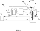
- FIG. 1A exemplarily illustrates a schematic view of a heat pump system 100 for optimizing operational efficiency without charge imbalance during a heating mode according to one or more embodiments of the invention.
- the heat pump system 100 for optimizing operational efficiency without charge imbalance includes an indoor HVAC unit 101 having an indoor coil and an outdoor HVAC unit 102 in communication with the indoor HVAC unit 101.
- the outdoor HVAC unit 102 includes a vapor header 103, a compressor 104 in communication with a reversing valve 105, and an outdoor coil 106 in communication with the indoor HVAC unit 101 and the compressor 104.
- the outdoor coil 106 includes at least one charge storage circuit 107. During the heating mode, the at least one charge storage circuit 107 stores refrigerant charge.
- the outdoor coil 106 may also include a plurality of fluid circuits 106a instead of a single fluid circuit in addition to the at least one charge storage circuit 107.
- the plurality of fluid circuits 106a may be spaced apart from each other in a linear direction.
- the number of plurality of fluid circuits 106a are kept greater than the number of the at least one charge storage circuit 107.
- the heating efficiency of the heat pump system 100 is improved.
- the number of fluid circuits may not be greater than the number of charge storage circuits to be an effective method for reducing charge imbalance.
- the function of the at least one charge storage circuit 107 in the heating mode is to contain liquid refrigerant in the outdoor coil 106 before the liquid refrigerant gets to an expansion valve 108.
- the expansion valve 108 is located between the at least one charge storage circuit 107 and the plurality of fluid circuits 106a. Since liquid has a higher density than vapor, this allows the outdoor coil 106 to hold more refrigerant charge than if all the plurality of fluid circuits 106a and the at least one charge storage circuit 107 were being used for evaporation and thus helps reduce charge imbalance.
- the outdoor HVAC unit 102 When the indoor HVAC unit 101 functions as the condenser (the heat pump system 100 is in the heating mode of operation), the outdoor HVAC unit 102 operates as an evaporator.
- the indoor HVAC unit 101 When the indoor HVAC unit 101 operates as the condenser, the high pressure refrigerant vapor condenses to a refrigerant liquid in the indoor HVAC unit 101.
- the compressed refrigerant vapor flows from the compressor 104 and then into the indoor HVAC unit 101.
- the indoor HVAC unit 101 is adapted to receive vapor refrigerant exiting the outdoor coil 106 via the compressor 104.
- the indoor HVAC unit 101 is adapted to return liquid refrigerant to the outdoor HVAC unit 102.
- the refrigerant from the outdoor HVAC unit 102 After passing through the indoor HVAC unit 101 and the outdoor HVAC unit 102, the refrigerant from the outdoor HVAC unit 102 returns to the suction line of the compressor 104 via the reversing valve 105.
- the reversing valve 105 may be provided to reverse refrigerant flow when the heat pump system 100 alternates between the heating mode and the cooling mode. In the heat pump system 100, most of the charge ends up being contained in whichever coil is acting as the condenser. When the outdoor coil 106 contains a significant amount more volume than the indoor coil, this can lead to a charge imbalance.
- the heat pump system 100 When the heat pump system 100 operates with a charge imbalance, the heat pump system 100 causes the indoor coil to contain more refrigerant than is optimal which causes the heat pump system 100 to operate at higher pressure to contain the refrigerant. This higher pressure can lead to less efficient heating operation or even cause the heat pump system 100 to shut down from high discharge pressure protection.
- the outdoor coil 106 of the outdoor HVAC unit 102 includes the plurality of fluid circuits 106a and the at least one charge storage circuit 107.
- the expansion valve 108 is located between the at least one charge storage circuit 107 and the plurality of fluid circuits 106a.
- the at least one charge storage circuit 107 contains liquid refrigerant.
- FIG. 1B exemplarily illustrates a schematic view of the heat pump system 100 for optimizing operational efficiency during a cooling mode according to one or more embodiments of the invention.
- the liquid refrigerant flows into the indoor HVAC unit 101 and the at least one charge storage circuit 107 functions as a subcooling circuit.
- the indoor HVAC unit 101 is adapted to receive liquid refrigerant from the outdoor coil 106.
- the indoor HVAC unit 101 is adapted to supply vapor refrigerant to the compressor 104 that will compress the refrigerant and then condense the vapor in the outdoor coil 106.
- the indoor HVAC unit 101 When the outdoor HVAC unit 102 is operating as the condenser, (the heat pump system 100 is in the cooling mode of operation), the indoor HVAC unit 101 operates as the evaporator.
- the liquid refrigerant goes through the expansion valve 108 and then is changed to a vaporous gas in the indoor HVAC unit 101.
- the compressed refrigerant is passed from the compressor 104 into the outdoor coil 106 where the refrigerant condenses.
- the liquid refrigerant then flows to the indoor HVAC unit 101, which functions as the evaporator.
- the gaseous refrigerant passes from the indoor HVAC unit 101 into the suction line of the compressor 104 via the reversing valve 105.
- the outdoor coil 106 of the outdoor HVAC unit 102 includes the plurality of fluid circuits 106a and the at least one charge storage circuit 107.
- the expansion valve 108 is located between the at least one charge storage circuit 107 and the plurality of fluid circuits 106a. During the cooling mode, the expansion device is bypassed and not used for expansion.
- the plurality of fluid circuits 106a apart from the at least one charge storage circuit 107 have refrigerant with the highest vapor content that causes a higher pressure drop.
- the pressure drop may be reduced significantly. After most of the refrigerant vapor has condensed into liquid, the pressure drop is reduced significantly. This means the refrigerant can be passed through fewer circuits to finish condensing and then be subcooled.
- the refrigerant vapor exchanges maximum heat.
- the refrigerant vapor reaches the at least one charge storage circuit 107, the refrigerant vapor is mostly condensed to refrigerant liquid. Therefore, the provision of the at least one charge storage circuit 107 that is less in number than the plurality of fluid circuits, the at least one charge storage circuit 107 functions as a subcooling circuit thereby improving the cooling efficiency of the heat pump system 100.
- the heat pump system 100 may include four charge storage circuits 107 and eight fluid circuits 106a.
- Each of the four charge storage circuits 107 and each of the eight fluid circuits include eight tubes. Therefore, the total number of tubes of the heat pump system 100 equals 96 in number. So, of the 96 tubes in the coil of the outdoor HVAC unit 102, 32 of them function as charge storage circuits 107 in heating and the remaining 64 tubes of the eight fluid circuits 106a are used to evaporate refrigerant after expansion. When the entire coil is used as an evaporator, the coil holds somewhere around 1.5 to 2.0 lbs. (0.7 to 0.9 kg) of refrigerant. With 32 of the 96 tubes holding liquid, the coil of the outdoor HVAC unit may hold about 8 lbs.
- FIG. 3 exemplarily illustrates a flowchart indicating a method 200 for optimizing operational efficiency without charge imbalance in the heat pump system 100 operating in at least one of the heating mode and the cooling mode.
- the method 200 for optimizing operational efficiency of the heat pump system 100 without charge imbalance is disclosed.
- the heat pump system 100 is operated in at least one of the heating mode and the cooling mode.
- the heat pump system 100 includes the indoor HVAC unit 101 having the indoor coil and the outdoor HVAC unit 102 in communication with the indoor HVAC unit 101.
- the outdoor HVAC unit 102 includes the outdoor coil 106, the compressor 104 in communication with the reversing valve 105, and the outdoor coil 106 in communication with the indoor HVAC unit 101 and the compressor 104.
- the outdoor coil 106 includes at least one charge storage circuit 107.
- the outdoor coil 106 includes a plurality of fluid circuits 106a and the at least one charge storage circuit 107.
- the plurality of fluid circuits 106a may be spaced apart from each other in a linear direction.
- the liquid refrigerant is supplied into the indoor HVAC unit 101 during the cooling mode.
- the indoor HVAC unit 101 when operating in the cooling mode, is configured to receive liquid refrigerant from the outdoor coil 106 and supply vapor refrigerant to the compressor 104 before returning to the outdoor coil 106.
- the at least one charge storage circuit 107 is configured to function as the subcooling circuit during the cooling mode.
- the at least one charge storage circuit 107 is configured to contain refrigerant charge during the heating mode.
- the indoor HVAC unit 101 when operating in the heating mode, is configured to receive vapor refrigerant exiting the compressor 104 and return liquid refrigerant to the outdoor HVAC unit 102.
Landscapes
- Engineering & Computer Science (AREA)
- Mechanical Engineering (AREA)
- General Engineering & Computer Science (AREA)
- Physics & Mathematics (AREA)
- Thermal Sciences (AREA)
- Life Sciences & Earth Sciences (AREA)
- Sustainable Development (AREA)
- Chemical & Material Sciences (AREA)
- Combustion & Propulsion (AREA)
- Compression-Type Refrigeration Machines With Reversible Cycles (AREA)
- Air Conditioning Control Device (AREA)
Abstract
Description
- The invention generally relates to heat pumps. More particularly, the invention relates to a system and method for optimizing operational efficiency without charge imbalance in a heat pump.
- Heat pumps are a type of refrigeration system that offers a versatile solution for both heating and cooling environments. They operate by utilizing the principles of thermodynamics and the properties of refrigerants to transfer heat energy from one place to another. Heat pumps can extract heat from the outdoor air, ground, or water sources and deliver it indoors to provide warmth during colder seasons. Conversely, they can also absorb heat from indoor spaces and release the heat outside to cool the air during warmer periods. This dual functionality makes heat pumps highly efficient and environmentally friendly, as they can provide both heating and cooling without using separate systems.
- In a basic heat pump system, a crucial component is the compressor, which plays a vital role in the heat transfer process. The compressor compresses the refrigerant, increasing the temperature and pressure of the refrigerant. The heated refrigerant is then directed through a refrigerant flow reversing device, typically a four-way reversing valve, which determines whether the heat pump operates in heating or cooling mode.
- When the heat pump is in cooling mode, the refrigerant flows to the outdoor heat exchanger, also known as the outdoor coil. Here, the refrigerant releases heat to the outdoor air, causing the refrigerant to cool down. The cooled refrigerant then passes through an expansion device, which reduces the pressure of the refrigerant, and continues to the indoor heat exchanger, or indoor coil. In the indoor coil, the refrigerant absorbs heat from the indoor air, cooling the indoor air. The heated refrigerant flows back to the compressor to start the cycle anew.
- On the other hand, in heating mode, the refrigerant follows a reverse path. The refrigerant moves from the indoor coil to the expansion device, where the refrigerant pressure drops, and then proceeds to the outdoor coil. In the outdoor coil, the refrigerant absorbs heat from the outdoor air, even in low temperatures. The heated refrigerant returns to the compressor, and the cycle continues.
- Efficiency plays a critical role in the design and operation of heat pump systems. Maximizing the effectiveness of the heat exchangers, both the indoor and outdoor coils, directly contributes to enhanced system efficiency and reduced overall costs. However, achieving a higher efficiency has become increasingly challenging. For instance, while increasing the size of the outdoor coil can improve efficiency, the size of the indoor coil is limited by standardized dimensions for indoor units. This discrepancy in coil sizes can lead to charge imbalances, negatively impacting heating performance.
- In recent years, manufacturers and designers are focusing on optimizing heat exchanger designs, improving refrigerant flow distribution, and employing advanced control algorithms. These efforts aim to strike a better balance between coil sizes and refrigerant charge resulting in improved heating performance and overall system efficiency for heat pump systems. By continually pushing the boundaries of heat exchanger design, the industry is striving to unlock greater efficiency potential and advance the capabilities of heat pump technology.
- This summary is provided to introduce a selection of concepts in a simplified format that are further described in the detailed description of the invention. This summary is not intended to identify key or essential inventive concepts of the specification, nor is it intended for determining the scope of the invention, which is as set out in the appended claims.
- According to a first aspect of the invention there is provided a heat pump system for optimizing operational efficiency without charge imbalance. The heat pump system includes an indoor HVAC unit having an indoor coil and an outdoor HVAC unit in communication with the indoor HVAC unit. The outdoor HVAC unit includes a compressor in communication with a reversing valve, and an outdoor coil in communication with the indoor HVAC unit and the compressor. The outdoor coil includes at least one charge storage circuit. During a cooling mode, the liquid refrigerant flows into the indoor HVAC unit and the at least one charge storage circuit functions as a subcooling circuit. During a heating mode, the at least one charge storage circuit contains liquid refrigerant.
- Optionally, the outdoor coil includes a plurality of fluid circuits and the at least one charge storage circuit.
- Optionally, the outdoor HVAC unit also includes an expansion valve located between the at least one charge storage circuit and the plurality of fluid circuits.
- Optionally, the plurality of fluid circuits are spaced apart from each other in a linear direction.
- Optionally, the number of plurality of fluid circuits are greater than the number of the at least one charge storage circuit.
- Optionally, when operating in the cooling mode, the indoor HVAC unit is adapted to receive liquid refrigerant from the outdoor coil and supply vapor refrigerant to the compressor before returning to the outdoor coil.
- Optionally, when operating in the heating mode, the indoor HVAC unit is adapted to receive vapor refrigerant exiting the compressor and return liquid refrigerant to the outdoor HVAC unit.
- According to a second aspect of the invention there is provided an outdoor HVAC unit including an outdoor coil in communication with an indoor HVAC unit and a compressor. The outdoor coil includes a plurality of fluid circuits and at least one charge storage circuit. An expansion valve is located between the at least one charge storage circuit and the plurality of fluid circuits. During a cooling mode, the liquid refrigerant flows into the indoor HVAC unit and the at least one charge storage circuit functions as a subcooling circuit. During a heating mode, the at least one charge storage circuit contains liquid refrigerant.
- According to a third aspect of the invention there is provided a method for optimizing operational efficiency of a heat pump system without charge imbalance. The method includes operating the heat pump system in at least one of a heating mode and a cooling mode. The heat pump system includes an indoor HVAC unit having an indoor coil and an outdoor HVAC unit in communication with the indoor HVAC unit. The outdoor HVAC unit includes an outdoor coil, a compressor in communication with a reversing valve, a vapor line in communication with the indoor HVAC unit and the compressor, such that the outdoor coil includes at least one charge storage circuit. The liquid refrigerant is supplied into the indoor HVAC unit during the cooling mode. The at least one charge storage circuit is configured to function as a subcooling circuit during the cooling mode. The at least one charge storage circuit is configured to contain liquid refrigerant during the heating mode.
- Optionally, the outdoor coil includes a plurality of fluid circuits and the at least one charge storage circuit.
- Optionally, the method includes spacing the plurality of fluid circuits apart from each other in a linear direction.
- Optionally, the number of plurality of fluid circuits are greater than the number of the at least one charge storage circuit.
- Optionally, when operating in the cooling mode, the method includes configuring the indoor HVAC unit to receive liquid refrigerant from the outdoor coil and supply vapor refrigerant to the compressor before returning to the outdoor coil.
- Optionally, when operating in the heating mode, the method includes configuring the indoor HVAC unit to receive vapor refrigerant exiting the compressor and return liquid refrigerant to the outdoor HVAC unit.
- To further clarify the advantages and features of the methods, systems, and apparatuses, a more particular description of the methods, systems, and apparatuses will be rendered by reference to specific embodiments thereof, which are illustrated in the appended drawings. It is appreciated that these drawings depict only typical embodiments of the invention and are therefore not to be considered limiting of its scope, which is as set out in the appended claims. The invention will be described and explained with additional specificity and detail with the accompanying drawings.
- These and other features, aspects, and advantages of the invention will become better understood when the following detailed description is read with reference to the accompanying drawings in which like characters represent like parts throughout the drawings. Certain exemplary embodiments will now be described in greater detail by way of example only and with reference to the accompanying drawings in which:
-
FIG. 1A exemplarily illustrates a schematic view of a heat pump system for optimizing operational efficiency without charge imbalance during a heating mode; -
FIG. 1B exemplarily illustrates a schematic view of the heat pump system for optimizing operational efficiency without charge imbalance during a cooling mode; and -
FIG. 2 exemplarily illustrates a flowchart indicating a method for optimizing operational efficiency without charge imbalance in the heat pump system operating in at least one of the heating mode and the cooling mode. - Further, skilled artisans will appreciate that elements in the drawings are illustrated for simplicity and may not have necessarily been drawn to scale. For example, the flow charts illustrate the method in terms of the most prominent steps involved to help to improve understanding of aspects of the invention. Furthermore, in terms of the construction of the device, one or more components of the device may have been represented in the drawings by conventional symbols, and the drawings may show only those specific details that are pertinent to understanding the embodiments of the invention so as not to obscure the drawings with details that will be readily apparent to those of ordinary skill in the art having the benefit of the description herein.
- For the purpose of promoting an understanding of the principles of the specification, reference will now be made to the various embodiments and specific language will be used to describe the same. It will nevertheless be understood that no limitation of the scope of the invention is thereby intended, such alterations and further modifications in the illustrated system, and such further applications of the principles of the specification as illustrated therein being contemplated as would normally occur to one skilled in the art to which the invention relates.
- It will be understood by those skilled in the art that the foregoing general description and the following detailed description are explanatory of the invention and are not intended to be restrictive thereof.
- Reference throughout this specification to "an aspect", "another aspect" or similar language means that a particular feature, structure, or characteristic described in connection with the embodiment is included in at least one embodiment of the invention. Thus, appearances of the phrase "in an embodiment", "in another embodiment", "some embodiments", "one or more embodiments" and similar language throughout this specification may, but do not necessarily, all refer to the same embodiment.
- The terms "comprises", "comprising", or any other variations thereof, are intended to cover a non-exclusive inclusion, such that a process or method that comprises a list of steps does not include only those steps but may include other steps not expressly listed or inherent to such process or method. Similarly, one or more devices or sub-systems or elements or structures or components proceeded by "comprises... a" does not, without more constraints, preclude the existence of other devices or other sub-systems or other elements or other structures or other components or additional devices or additional sub-systems or additional elements or additional structures or additional components.
- Embodiments of the invention will be described below in detail with reference to the accompanying drawings.
- Heat pump systems are a type of refrigeration system that offers a versatile solution for both heating and cooling environments. They operate by utilizing the principles of thermodynamics and the properties of refrigerants to transfer heat energy from one place to another. The heat pump system may extract heat from the outdoor air, ground, or water sources and deliver the extracted heat indoors to provide warmth during colder seasons. Conversely, they can also absorb heat from indoor spaces and release the heat outside to cool the air during warmer periods. This dual functionality makes the heat pump systems highly efficient and environmentally friendly, as they can provide both heating and cooling without using separate systems.
- When trying to achieve higher efficiency in the heat pump systems, there are a couple of factors that limit improvements in efficiency. Firstly, outdoor coils of the heat pump system may be limited in size when compared to indoor coils to prevent charge imbalance in a heating mode. Secondly, refrigerant flow in both directions is desirable in existing heat pump systems which typically prevents the use of a subcooler in a cooling mode.
-
FIG. 1A exemplarily illustrates a schematic view of aheat pump system 100 for optimizing operational efficiency without charge imbalance during a heating mode according to one or more embodiments of the invention. Theheat pump system 100 for optimizing operational efficiency without charge imbalance includes anindoor HVAC unit 101 having an indoor coil and anoutdoor HVAC unit 102 in communication with theindoor HVAC unit 101. Theoutdoor HVAC unit 102 includes avapor header 103, acompressor 104 in communication with a reversingvalve 105, and anoutdoor coil 106 in communication with theindoor HVAC unit 101 and thecompressor 104. - The
outdoor coil 106 includes at least onecharge storage circuit 107. During the heating mode, the at least onecharge storage circuit 107 stores refrigerant charge. In an embodiment, theoutdoor coil 106 may also include a plurality offluid circuits 106a instead of a single fluid circuit in addition to the at least onecharge storage circuit 107. The plurality offluid circuits 106a may be spaced apart from each other in a linear direction. The number of plurality offluid circuits 106a are kept greater than the number of the at least onecharge storage circuit 107. By optionally increasing the number of the plurality offluid circuits 106a in comparison to the number of the at least one storage circuit, the heating efficiency of theheat pump system 100 is improved. However, it may be appreciated that the number of fluid circuits may not be greater than the number of charge storage circuits to be an effective method for reducing charge imbalance. - The function of the at least one
charge storage circuit 107 in the heating mode is to contain liquid refrigerant in theoutdoor coil 106 before the liquid refrigerant gets to anexpansion valve 108. In an embodiment, theexpansion valve 108 is located between the at least onecharge storage circuit 107 and the plurality offluid circuits 106a. Since liquid has a higher density than vapor, this allows theoutdoor coil 106 to hold more refrigerant charge than if all the plurality offluid circuits 106a and the at least onecharge storage circuit 107 were being used for evaporation and thus helps reduce charge imbalance. As such, the orientation of thecharge storage circuits 107 with regards to thefluid evaporating circuits 106a contributes to the heat being recaptured from the warmer liquid refrigerant in thecharge storage circuits 107. As shown inFIG. 1A , air blows across theoutdoor coil 106 from left to right. The warmer refrigerant in the at least onecharge storage circuit 107 will add heat to the air that gets blown onto the inner row of the plurality offluid circuits 106a. - When the
indoor HVAC unit 101 functions as the condenser (theheat pump system 100 is in the heating mode of operation), theoutdoor HVAC unit 102 operates as an evaporator. When theindoor HVAC unit 101 operates as the condenser, the high pressure refrigerant vapor condenses to a refrigerant liquid in theindoor HVAC unit 101. During the heating cycle, the compressed refrigerant vapor flows from thecompressor 104 and then into theindoor HVAC unit 101. This means when operating in the heating mode, theindoor HVAC unit 101 is adapted to receive vapor refrigerant exiting theoutdoor coil 106 via thecompressor 104. Moreover, theindoor HVAC unit 101 is adapted to return liquid refrigerant to theoutdoor HVAC unit 102. After passing through theindoor HVAC unit 101 and theoutdoor HVAC unit 102, the refrigerant from theoutdoor HVAC unit 102 returns to the suction line of thecompressor 104 via the reversingvalve 105. In an embodiment, the reversingvalve 105 may be provided to reverse refrigerant flow when theheat pump system 100 alternates between the heating mode and the cooling mode. In theheat pump system 100, most of the charge ends up being contained in whichever coil is acting as the condenser. When theoutdoor coil 106 contains a significant amount more volume than the indoor coil, this can lead to a charge imbalance. When theheat pump system 100 operates with a charge imbalance, theheat pump system 100 causes the indoor coil to contain more refrigerant than is optimal which causes theheat pump system 100 to operate at higher pressure to contain the refrigerant. This higher pressure can lead to less efficient heating operation or even cause theheat pump system 100 to shut down from high discharge pressure protection. - In an embodiment, the
outdoor coil 106 of theoutdoor HVAC unit 102 includes the plurality offluid circuits 106a and the at least onecharge storage circuit 107. Theexpansion valve 108 is located between the at least onecharge storage circuit 107 and the plurality offluid circuits 106a. During the heating mode, the at least onecharge storage circuit 107 contains liquid refrigerant. -
FIG. 1B exemplarily illustrates a schematic view of theheat pump system 100 for optimizing operational efficiency during a cooling mode according to one or more embodiments of the invention. During the cooling mode, the liquid refrigerant flows into theindoor HVAC unit 101 and the at least onecharge storage circuit 107 functions as a subcooling circuit. This means when operating in the cooling mode, theindoor HVAC unit 101 is adapted to receive liquid refrigerant from theoutdoor coil 106. Moreover, theindoor HVAC unit 101 is adapted to supply vapor refrigerant to thecompressor 104 that will compress the refrigerant and then condense the vapor in theoutdoor coil 106. - When the
outdoor HVAC unit 102 is operating as the condenser, (theheat pump system 100 is in the cooling mode of operation), theindoor HVAC unit 101 operates as the evaporator. When operating as the evaporator, the liquid refrigerant goes through theexpansion valve 108 and then is changed to a vaporous gas in theindoor HVAC unit 101. The compressed refrigerant is passed from thecompressor 104 into theoutdoor coil 106 where the refrigerant condenses. The liquid refrigerant then flows to theindoor HVAC unit 101, which functions as the evaporator. The gaseous refrigerant passes from theindoor HVAC unit 101 into the suction line of thecompressor 104 via the reversingvalve 105. - In an embodiment, the
outdoor coil 106 of theoutdoor HVAC unit 102 includes the plurality offluid circuits 106a and the at least onecharge storage circuit 107. Theexpansion valve 108 is located between the at least onecharge storage circuit 107 and the plurality offluid circuits 106a. During the cooling mode, the expansion device is bypassed and not used for expansion. - The plurality of
fluid circuits 106a apart from the at least onecharge storage circuit 107 have refrigerant with the highest vapor content that causes a higher pressure drop. By increasing the number offluid circuits 106a, the pressure drop may be reduced significantly. After most of the refrigerant vapor has condensed into liquid, the pressure drop is reduced significantly. This means the refrigerant can be passed through fewer circuits to finish condensing and then be subcooled. By using the plurality offluid circuits 106a when the refrigerant is mostly vapor, the refrigerant vapor exchanges maximum heat. Moreover, when the refrigerant vapor reaches the at least onecharge storage circuit 107, the refrigerant vapor is mostly condensed to refrigerant liquid. Therefore, the provision of the at least onecharge storage circuit 107 that is less in number than the plurality of fluid circuits, the at least onecharge storage circuit 107 functions as a subcooling circuit thereby improving the cooling efficiency of theheat pump system 100. - In an embodiment, the
heat pump system 100 may include fourcharge storage circuits 107 and eightfluid circuits 106a. Each of the fourcharge storage circuits 107 and each of the eight fluid circuits include eight tubes. Therefore, the total number of tubes of theheat pump system 100 equals 96 in number. So, of the 96 tubes in the coil of theoutdoor HVAC unit 102, 32 of them function ascharge storage circuits 107 in heating and the remaining 64 tubes of the eightfluid circuits 106a are used to evaporate refrigerant after expansion. When the entire coil is used as an evaporator, the coil holds somewhere around 1.5 to 2.0 lbs. (0.7 to 0.9 kg) of refrigerant. With 32 of the 96 tubes holding liquid, the coil of the outdoor HVAC unit may hold about 8 lbs. (4 kg) of refrigerant. Furthermore, with the configuration of the subcooling circuits in the outer row of the coil, the heat that is lost while the liquid is in the subcooling circuits can be recaptured by the tubes in the inner row. Advantageously, this design ensures lower implementation cost than incorporating a traditional charge compensator in theoutdoor HVAC unit 102. - FIG. 3 exemplarily illustrates a flowchart indicating a
method 200 for optimizing operational efficiency without charge imbalance in theheat pump system 100 operating in at least one of the heating mode and the cooling mode. Themethod 200 for optimizing operational efficiency of theheat pump system 100 without charge imbalance, is disclosed. - At
Step 201, theheat pump system 100 is operated in at least one of the heating mode and the cooling mode. Theheat pump system 100 includes theindoor HVAC unit 101 having the indoor coil and theoutdoor HVAC unit 102 in communication with theindoor HVAC unit 101. Theoutdoor HVAC unit 102 includes theoutdoor coil 106, thecompressor 104 in communication with the reversingvalve 105, and theoutdoor coil 106 in communication with theindoor HVAC unit 101 and thecompressor 104. Theoutdoor coil 106 includes at least onecharge storage circuit 107. In an embodiment, theoutdoor coil 106 includes a plurality offluid circuits 106a and the at least onecharge storage circuit 107. In an embodiment, the plurality offluid circuits 106a may be spaced apart from each other in a linear direction. - At
Step 202, the liquid refrigerant is supplied into theindoor HVAC unit 101 during the cooling mode. In an embodiment, theindoor HVAC unit 101, when operating in the cooling mode, is configured to receive liquid refrigerant from theoutdoor coil 106 and supply vapor refrigerant to thecompressor 104 before returning to theoutdoor coil 106. - At
Step 203, the at least onecharge storage circuit 107 is configured to function as the subcooling circuit during the cooling mode. - At
Step 204, the at least onecharge storage circuit 107 is configured to contain refrigerant charge during the heating mode. In an embodiment, theindoor HVAC unit 101, when operating in the heating mode, is configured to receive vapor refrigerant exiting thecompressor 104 and return liquid refrigerant to theoutdoor HVAC unit 102. - While specific language has been used to describe the subject matter, any limitations arising on account thereto, are not intended. As would be apparent to a person in the art, various working modifications may be made to the method in order to implement the inventive concept as taught herein. The drawings and the foregoing description give examples of embodiments. Those skilled in the art will appreciate that one or more of the described elements may well be combined into a single functional element. Alternatively, certain elements may be split into multiple functional elements. Elements from one embodiment may be added to another embodiment.
Claims (14)
- A heat pump system (100) for optimizing operational efficiency without charge imbalance, the heat pump system comprising:an indoor HVAC unit (101) comprising an indoor coil; andan outdoor HVAC unit (102) in communication with the indoor HVAC unit, the outdoor HVAC unit comprising:a compressor (104) in communication with a reversing valve (105); andan outdoor coil (106) in communication with the indoor HVAC unit and the compressor, the outdoor coil comprising at least one charge storage circuit (107),wherein, during a cooling mode, the liquid refrigerant flows into the indoor HVAC unit and the at least one charge storage circuit functions as a subcooling circuit, andwherein, during a heating mode, the at least one charge storage circuit contains liquid refrigerant.
- The heat pump system of claim 1, wherein the outdoor coil (106) comprises:a plurality of fluid circuits (1 06a); andthe at least one charge storage circuit (107).
- The heat pump system according to claim 2, wherein the outdoor HVAC unit (102) further comprises an expansion valve (108) located between the at least one charge storage circuit (107) and the plurality of fluid circuits (106a).
- The heat pump system of claim 2 or 3, wherein the plurality of fluid circuits (106a) are spaced apart from each other in a linear direction.
- The heat pump system of any of claims 2 to 4, wherein the number of plurality of fluid circuits (106a) are greater than the number of the at least one charge storage circuit (107).
- The heat pump system of any preceding claim, wherein, when operating in the cooling mode, the indoor HVAC unit (101) is adapted to:receive liquid refrigerant from the outdoor coil (106); andsupply vapor refrigerant to the compressor (104) before returning to the outdoor coil.
- The heat pump system of any preceding claim, wherein, when operating in the heating mode, the indoor HVAC unit (101) is adapted to:receive vapor refrigerant exiting the compressor (104); andreturn liquid refrigerant to the outdoor HVAC unit (102).
- An outdoor HVAC unit (102) comprising:a compressor (104);an outdoor coil (106) in communication with an indoor HVAC unit (101) and the compressor, the outdoor coil comprising:a plurality of fluid circuits (106a);at least one charge storage circuit (107); andan expansion valve (108) located between the at least one charge storage circuit and the plurality of fluid circuits,wherein, during a cooling mode, the liquid refrigerant flows into the indoor HVAC unit and the at least one charge storage circuit functions as a subcooling circuit, andwherein, during a heating mode, the at least one charge storage circuit contains liquid refrigerant.
- A method for optimizing operational efficiency of a heat pump system (100) without charge imbalance, the method comprising:
operating (201) the heat pump system, in at least one of a heating mode and a cooling mode, the heat pump system comprising:an indoor HVAC unit (101) comprising an indoor coil; andan outdoor HVAC unit (102) in communication with the indoor HVAC unit, the outdoor HVAC unit comprising:a compressor (104) in communication with a reversing valve (105); andan outdoor coil (106) in communication with the indoor HVAC unit and the compressor, the outdoor coil comprising at least one charge storage circuit (107);supplying (202) liquid refrigerant into the indoor HVAC unit during the cooling mode;configuring (203) the at least one charge storage circuit to function as a subcooling circuit during the cooling mode; andconfiguring (204) the at least one charge storage circuit to contain liquid refrigerant during the heating mode. - The method of claim 9, wherein the outdoor coil (106) comprises:a plurality of fluid circuits (106a); andthe at least one charge storage circuit (107).
- The method of claim 10, including spacing the plurality of fluid circuits (106a) apart from each other in a linear direction.
- The method of claim 10 or 11, wherein the number of plurality of fluid circuits (106a) are greater than the number of the at least one charge storage circuit (107).
- The method of any of claims 9 to 12, further comprising when operating in the cooling mode, configuring the indoor HVAC unit (101) to:receive liquid refrigerant from the outdoor coil (106); andsupply vapor refrigerant to the compressor (104) before returning to the outdoor coil.
- The method of any of claims 9 to 13, further comprising when operating in the heating mode, configuring the indoor HVAC unit (101) to:receive vapor refrigerant exiting the outdoor coil (106) via the compressor (104); andreturn liquid refrigerant to the outdoor coil.
Applications Claiming Priority (1)
| Application Number | Priority Date | Filing Date | Title |
|---|---|---|---|
| US202363580807P | 2023-09-06 | 2023-09-06 |
Publications (1)
| Publication Number | Publication Date |
|---|---|
| EP4521037A1 true EP4521037A1 (en) | 2025-03-12 |
Family
ID=92424168
Family Applications (1)
| Application Number | Title | Priority Date | Filing Date |
|---|---|---|---|
| EP24194581.5A Pending EP4521037A1 (en) | 2023-09-06 | 2024-08-14 | A heat pump system for optimizing operational efficiency without charge imbalance and a method thereof |
Country Status (3)
| Country | Link |
|---|---|
| US (1) | US20250075949A1 (en) |
| EP (1) | EP4521037A1 (en) |
| CN (1) | CN119573275A (en) |
Citations (4)
| Publication number | Priority date | Publication date | Assignee | Title |
|---|---|---|---|---|
| US4045977A (en) * | 1976-09-09 | 1977-09-06 | Dunham-Bush, Inc. | Self operating excess refrigerant storage system for a heat pump |
| WO2008059737A1 (en) * | 2006-11-13 | 2008-05-22 | Daikin Industries, Ltd. | Air conditioning apparatus |
| CN104350338B (en) * | 2012-04-27 | 2016-04-20 | 三菱电机株式会社 | air conditioner |
| US11137156B2 (en) * | 2019-05-31 | 2021-10-05 | Trane International Inc | Refrigerant charge management with subcooling control |
Family Cites Families (4)
| Publication number | Priority date | Publication date | Assignee | Title |
|---|---|---|---|---|
| US5509272A (en) * | 1991-03-08 | 1996-04-23 | Hyde; Robert E. | Apparatus for dehumidifying air in an air-conditioned environment with climate control system |
| EP3264010B1 (en) * | 2015-02-27 | 2022-04-13 | Hitachi-Johnson Controls Air Conditioning, Inc. | Heat exchange apparatus and air conditioner using same |
| US11215388B2 (en) * | 2019-01-21 | 2022-01-04 | Carrier Corporation | Refrigerant charge management |
| US20240191917A1 (en) * | 2022-12-09 | 2024-06-13 | Allied Air Enterprises Llc | Heat pump charge compensation for cooling mode operation |
-
2024
- 2024-08-14 EP EP24194581.5A patent/EP4521037A1/en active Pending
- 2024-08-29 US US18/818,911 patent/US20250075949A1/en active Pending
- 2024-09-05 CN CN202411238168.6A patent/CN119573275A/en active Pending
Patent Citations (4)
| Publication number | Priority date | Publication date | Assignee | Title |
|---|---|---|---|---|
| US4045977A (en) * | 1976-09-09 | 1977-09-06 | Dunham-Bush, Inc. | Self operating excess refrigerant storage system for a heat pump |
| WO2008059737A1 (en) * | 2006-11-13 | 2008-05-22 | Daikin Industries, Ltd. | Air conditioning apparatus |
| CN104350338B (en) * | 2012-04-27 | 2016-04-20 | 三菱电机株式会社 | air conditioner |
| US11137156B2 (en) * | 2019-05-31 | 2021-10-05 | Trane International Inc | Refrigerant charge management with subcooling control |
Also Published As
| Publication number | Publication date |
|---|---|
| US20250075949A1 (en) | 2025-03-06 |
| CN119573275A (en) | 2025-03-07 |
Similar Documents
| Publication | Publication Date | Title |
|---|---|---|
| US7908881B2 (en) | HVAC system with powered subcooler | |
| US8713963B2 (en) | Economized vapor compression circuit | |
| JP5551882B2 (en) | Heat pump system | |
| US8146373B2 (en) | Accessory sub-cooling unit and method of use | |
| WO2007052898A1 (en) | Air conditioning system for communication equipment and controlling method thereof | |
| KR20100046365A (en) | Heat pump system | |
| US11092369B2 (en) | Integrated suction header assembly | |
| US8726684B2 (en) | Reversible system for recovering of heat energy by sampling and transfer of calories from one or more media into one or more other such media | |
| EP1186839A2 (en) | Refrigeration cycle | |
| US20250075949A1 (en) | Heat pump system for optimizing operational efficiencywithout charge imbalance and a method thereof | |
| KR100883600B1 (en) | Air conditioner | |
| EP2431685B1 (en) | Air conditioner | |
| KR20100005736U (en) | Heat pump system | |
| CN114502887A (en) | Refrigerating device | |
| KR101560825B1 (en) | Air conditioning system | |
| KR20050043089A (en) | Heat pump | |
| JP2004116930A (en) | Gas heat pump type air conditioner | |
| CN216203920U (en) | Air conditioner | |
| WO2007040031A1 (en) | Liquid gas heat exchanger for air conditioner | |
| US20240384552A1 (en) | Swimming Pool or Spa Heat Pump With Refrigerant Charge Compensator and Method of Operating Same | |
| KR20100005738U (en) | Hot water heat pump system | |
| EP4675202A1 (en) | Heat pump with integrated heat exchanger and method of heating a heat sink fluid | |
| JP2008145002A (en) | Air conditioning device | |
| KR980009958A (en) | Heat pump air conditioner | |
| KR20020090952A (en) | Heat pump cycle |
Legal Events
| Date | Code | Title | Description |
|---|---|---|---|
| PUAI | Public reference made under article 153(3) epc to a published international application that has entered the european phase |
Free format text: ORIGINAL CODE: 0009012 |
|
| STAA | Information on the status of an ep patent application or granted ep patent |
Free format text: STATUS: THE APPLICATION HAS BEEN PUBLISHED |
|
| AK | Designated contracting states |
Kind code of ref document: A1 Designated state(s): AL AT BE BG CH CY CZ DE DK EE ES FI FR GB GR HR HU IE IS IT LI LT LU LV MC ME MK MT NL NO PL PT RO RS SE SI SK SM TR |
|
| STAA | Information on the status of an ep patent application or granted ep patent |
Free format text: STATUS: REQUEST FOR EXAMINATION WAS MADE |
|
| 17P | Request for examination filed |
Effective date: 20250910 |
|
| STAA | Information on the status of an ep patent application or granted ep patent |
Free format text: STATUS: EXAMINATION IS IN PROGRESS |
|
| 17Q | First examination report despatched |
Effective date: 20260209 |