EP4520988A1 - Disconnection module, power transmission system for vehicle, and vehicle - Google Patents
Disconnection module, power transmission system for vehicle, and vehicle Download PDFInfo
- Publication number
- EP4520988A1 EP4520988A1 EP24197316.3A EP24197316A EP4520988A1 EP 4520988 A1 EP4520988 A1 EP 4520988A1 EP 24197316 A EP24197316 A EP 24197316A EP 4520988 A1 EP4520988 A1 EP 4520988A1
- Authority
- EP
- European Patent Office
- Prior art keywords
- sliding grooves
- axially
- clutch member
- disconnection module
- protrusions
- Prior art date
- Legal status (The legal status is an assumption and is not a legal conclusion. Google has not performed a legal analysis and makes no representation as to the accuracy of the status listed.)
- Pending
Links
Images




Classifications
-
- F—MECHANICAL ENGINEERING; LIGHTING; HEATING; WEAPONS; BLASTING
- F16—ENGINEERING ELEMENTS AND UNITS; GENERAL MEASURES FOR PRODUCING AND MAINTAINING EFFECTIVE FUNCTIONING OF MACHINES OR INSTALLATIONS; THERMAL INSULATION IN GENERAL
- F16D—COUPLINGS FOR TRANSMITTING ROTATION; CLUTCHES; BRAKES
- F16D11/00—Clutches in which the members have interengaging parts
- F16D11/14—Clutches in which the members have interengaging parts with clutching members movable only axially
-
- F—MECHANICAL ENGINEERING; LIGHTING; HEATING; WEAPONS; BLASTING
- F16—ENGINEERING ELEMENTS AND UNITS; GENERAL MEASURES FOR PRODUCING AND MAINTAINING EFFECTIVE FUNCTIONING OF MACHINES OR INSTALLATIONS; THERMAL INSULATION IN GENERAL
- F16D—COUPLINGS FOR TRANSMITTING ROTATION; CLUTCHES; BRAKES
- F16D11/00—Clutches in which the members have interengaging parts
- F16D11/08—Clutches in which the members have interengaging parts actuated by moving a non-rotating part axially
- F16D11/10—Clutches in which the members have interengaging parts actuated by moving a non-rotating part axially with clutching members movable only axially
-
- F—MECHANICAL ENGINEERING; LIGHTING; HEATING; WEAPONS; BLASTING
- F16—ENGINEERING ELEMENTS AND UNITS; GENERAL MEASURES FOR PRODUCING AND MAINTAINING EFFECTIVE FUNCTIONING OF MACHINES OR INSTALLATIONS; THERMAL INSULATION IN GENERAL
- F16D—COUPLINGS FOR TRANSMITTING ROTATION; CLUTCHES; BRAKES
- F16D27/00—Magnetically- or electrically- actuated clutches; Control or electric circuits therefor
- F16D27/14—Details
-
- F—MECHANICAL ENGINEERING; LIGHTING; HEATING; WEAPONS; BLASTING
- F16—ENGINEERING ELEMENTS AND UNITS; GENERAL MEASURES FOR PRODUCING AND MAINTAINING EFFECTIVE FUNCTIONING OF MACHINES OR INSTALLATIONS; THERMAL INSULATION IN GENERAL
- F16D—COUPLINGS FOR TRANSMITTING ROTATION; CLUTCHES; BRAKES
- F16D11/00—Clutches in which the members have interengaging parts
-
- F—MECHANICAL ENGINEERING; LIGHTING; HEATING; WEAPONS; BLASTING
- F16—ENGINEERING ELEMENTS AND UNITS; GENERAL MEASURES FOR PRODUCING AND MAINTAINING EFFECTIVE FUNCTIONING OF MACHINES OR INSTALLATIONS; THERMAL INSULATION IN GENERAL
- F16D—COUPLINGS FOR TRANSMITTING ROTATION; CLUTCHES; BRAKES
- F16D23/00—Details of mechanically-actuated clutches not specific for one distinct type
- F16D23/12—Mechanical clutch-actuating mechanisms arranged outside the clutch as such
-
- F—MECHANICAL ENGINEERING; LIGHTING; HEATING; WEAPONS; BLASTING
- F16—ENGINEERING ELEMENTS AND UNITS; GENERAL MEASURES FOR PRODUCING AND MAINTAINING EFFECTIVE FUNCTIONING OF MACHINES OR INSTALLATIONS; THERMAL INSULATION IN GENERAL
- F16D—COUPLINGS FOR TRANSMITTING ROTATION; CLUTCHES; BRAKES
- F16D27/00—Magnetically- or electrically- actuated clutches; Control or electric circuits therefor
- F16D27/10—Magnetically- or electrically- actuated clutches; Control or electric circuits therefor with an electromagnet not rotating with a clutching member, i.e. without collecting rings
- F16D27/118—Magnetically- or electrically- actuated clutches; Control or electric circuits therefor with an electromagnet not rotating with a clutching member, i.e. without collecting rings with interengaging jaws or gear teeth
-
- F—MECHANICAL ENGINEERING; LIGHTING; HEATING; WEAPONS; BLASTING
- F16—ENGINEERING ELEMENTS AND UNITS; GENERAL MEASURES FOR PRODUCING AND MAINTAINING EFFECTIVE FUNCTIONING OF MACHINES OR INSTALLATIONS; THERMAL INSULATION IN GENERAL
- F16D—COUPLINGS FOR TRANSMITTING ROTATION; CLUTCHES; BRAKES
- F16D23/00—Details of mechanically-actuated clutches not specific for one distinct type
- F16D23/12—Mechanical clutch-actuating mechanisms arranged outside the clutch as such
- F16D2023/123—Clutch actuation by cams, ramps or ball-screw mechanisms
Definitions
- the present invention relates to a disconnection module for engaging or disengaging a first component rotatable about a first shaft with or from the first shaft.
- the present invention further relates to a power transmission system for a vehicle, which comprises the disconnection module.
- the present invention also relates to a vehicle, which comprises the power transmission system.
- auxiliary drive motors are used only during acceleration or special working conditions, or when a driver needs to obtain some high-performance modes.
- the wheel will still drive the auxiliary drive differential to operate, and the differential will drive all transmission mechanisms and motors connected thereto to rotate together, thereby generating drag losses.
- a disconnection module is added to the power transmission system of the electric vehicle, thereby reducing drag losses.
- a conventional disconnection module usually adopts a monostable mode. That is, to realize that the auxiliary drive motors are in a working state, the actuator of the disconnection module needs to remain energized so that the disconnection module is in an engaged state. Therefore, the engaged state is an unstable state, and once the actuator is powered off, the disconnection module cannot maintain the engaged state. This means that the electric vehicle must continue to supply power for the actuator while the auxiliary drive motors are in the working state. Such energy consumption is a waste.
- the technical problem to be solved by the present invention is to overcome the above defects or shortcomings of the prior art, and the present invention provides a disconnection module, which can provide two stable states, namely a stable engaged state and a stable disengaged state, without consuming additional energy to maintain any state.
- a disconnection module for engaging or disengaging a first component rotatable about a first shaft with or from a first shaft, wherein the disconnection module comprises:
- the traditional clutch is split into two components, namely, the drive member and the clutch member, wherein the drive member is fixedly connected to the first component, the reset assembly is arranged on the side of the clutch member facing the drive member, and the actuator is arranged on the side of the clutch member away from the drive member.
- the reset assembly and the actuator cooperate with each other on two sides of the clutch member to provide the clutch member with a force to approach or move away from the drive member.
- the pressing assembly is arranged between the clutch member and the actuator, so that the clutch member can be in a stable engaged state and a stable disengaged state. That is, it is not necessary to continuously energize the actuator to maintain any of the two states, thereby greatly reducing energy consumption and realizing a bistable disconnection module.
- the pressing assembly comprises:
- the first protrusions have first inclined surfaces inclined in the same direction relative to a radial plane, respectively, and the second protrusions have abutting ends for abutting against the first inclined surfaces, respectively; wherein in each reciprocating movement of the action end, when the first protrusions are pushed to the outside of the sliding grooves by the second protrusions, the first protrusions can drive the pressure plate to rotate relative to the driven plate by a certain angle each time under the action force of the action end and the pressure applied by the reset assembly; wherein the guide member is further provided with end inclined surfaces cooperating with the first inclined surfaces of the pressure plate, so that the first protrusions of the pressure plate can move towards the disengagement direction during each rotation, thereby alternately entering the first sliding grooves and being stopped on the outside of the second sliding grooves.
- the guide member is provided with partition portions located between the first sliding grooves and the second sliding grooves, and the end inclined surfaces comprise second inclined surfaces assigned to the partition portions and third inclined surfaces assigned to the second sliding grooves, wherein the third inclined surfaces are adjacent to the second inclined surfaces, for example with a smooth transition.
- the partition portions comprise first partition portions located upstream of the second sliding grooves along a rotation direction of the pressure plate and second partition portions located downstream of the second sliding groove, and the second partition portions protrude axially from the third inclined surfaces of the second sliding grooves.
- the driven plate and/or the pressure plate are/is provided with a snap mechanism for preventing the driven plate from being axially separated from the pressure plate.
- the snap mechanism comprises a plurality of claws protruding from one of the driven plate and the pressure plate and capable of being snapped onto an edge of the other of the driven plate and the pressure plate.
- the edge is provided with an inclined groove extending obliquely to an axial direction, which is used to mount the claws and prevent the claws from being disengaged axially.
- the guide member is sleeved on the first shaft, and the driven plate and the pressure plate are separately sleeved on the guide member.
- the partition portions are protrusions.
- the guide member further has a second support section for rotationally and fixedly supporting the clutch member, and the second support section is axially spaced apart from the first support section.
- the guide member further has a third support section adjacent to the second support section
- the disconnection module comprises a retaining ring provided on the third support section
- the retaining ring is arranged on a side of the drive member close to the first component and has an axial gap with the drive member.
- the reset assembly comprises:
- the reset assembly further comprises:
- the second support gasket is provided with a protrusion stamped from one side, and the protrusion is used to support one end of the spring.
- the end surface bearing comprises a first support ring fixedly connected to the second support gasket and a second support ring fixedly connected to the clutch member.
- the first component is an idler gear in a speed reducer
- the drive member is fixedly connected to an end surface of the idler gear
- a power transmission system for a vehicle comprising: a motor having a drive shaft; a speed reducer having at least one transmission shaft; and the disconnection module described previously, wherein the first shaft comprises the drive shaft or the at least one transmission shaft.
- connection refers to a relationship in which the structures are fixed or attached to each other directly or indirectly through an intermediate structures.
- FIG. 1A schematically shows an exemplary embodiment of a disconnection module 10 according to the present invention
- FIG. 1B schematically shows a partial cross-sectional view of the disconnection module 10 of FIG. 1A .
- the disconnection module 10 is in an engaged state.
- the disconnection module 10 of the present invention may be roughly understood with reference to FIGS. 1A and 1B , wherein the disconnection module 10 includes:
- the traditional clutch is split into two components, namely, the drive member 1 and the clutch member 2, wherein the drive member 1 is fixedly connected to the first component 20, the reset assembly 3 is arranged on the side of the clutch member 2 facing the drive member 1, and the actuator 5 is arranged on the side of the clutch member 2 away from the drive member 1.
- the reset assembly 3 and the actuator 5 cooperate with each other on two sides of the clutch member to provide the clutch member 2 with a force to approach or move away from the drive member 1.
- the pressing assembly 3 is arranged between the clutch member and the actuator 5, so that the clutch member can be in a stable engaged state and a stable disengaged state. That is, it is not necessary to continuously energize the actuator to maintain any of the two states, thereby greatly reducing energy consumption and realizing a bistable disconnection module.
- rotating fixed means that two components can be connected to rotate together, and their mutual movement in a rotation direction (such as a circumferential direction) is restricted so that they can rotate together.
- the “rotatably fixed” does not restrict the displacement in a rotation axis direction, so the two rotatably fixed components may have relative displacement in the rotation axis direction. If the displacement in the rotation axis direction is also fixed, it can be considered that the two components are completely fixedly connected.
- first shaft 30 being independent of the first component 20 in the disengaged state means that the motion state of the first shaft 30 is independent of the motion state of the first component 20 at this time. That is, the first shaft 30 and the first component 20 can rotate independently of each other, but it does not mean that there is no connection between them.
- the clutch member 2 and the first shaft 30 are rotationally fixed by means of a spline connection, and the drive member 1 and the first component 20 are fixedly connected.
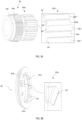
- FIG. 2 shows a perspective view of the drive member 1 and the clutch member 2 in FIG. 1A .
- the first component 20 is also shown.
- the first component 20 is an idler gear in a speed reducer here and has an end surface 21 facing the drive member 1.
- the drive member 1 is provided with a plurality of transmission pins 1a evenly distributed along a circumferential direction on the side facing the first component 20, a plurality of openings 21a evenly distributed along the circumferential direction are provided on the end surface of the first component 20 facing the drive member 1, and the transmission pins 1a can mesh with the openings 21a so that the drive member 1 is fixedly connected to the first component 20.
- Other connection manners may also be used within the scope of the present invention to achieve a fixed connection between the drive member 1 and the clutch member 2.
- the drive member 1 has a first engagement portion 1b
- the clutch member 2 has a second engagement portion 2b
- the first engagement portion can mesh with the second engagement portion.
- the first engagement portion 1b and the second engagement portion 2b are both configured as end surface teeth.
- the pressing assembly 4 includes a guide member 43, a pressure plate 41 and a driven plate 42.
- the pressure plate 41 and the driven plate 42 are both annular and concentrically mounted on the guide member 43, and the guide member 43 is sleeved on the first shaft 30.
- the pressure plate 41 abuts against the clutch member 2 on the left side, and the driven plate 42 is used to receive an action force from the action end 5a of the actuator 5 on the right side and transmit the action force to the pressure plate 41.
- FIGS. 3A to 3C schematically show the guide member 43, the pressure plate 41 and the driven plate 42 of the pressing assembly 4 in FIG. 1A , respectively.
- FIG. 3D schematically shows an assembly diagram of the pressure plate 41 and the driven plate 42.
- the guide member 43 has a first support section 43d for radially supporting the driven plate 42, a second support section 43e for rotatably and fixedly supporting the clutch member 2, and a third support section 43f adjacent to the second support section 43e, wherein the second support section 43e is axially spaced from the first support section 43d, thereby allowing the pressure plate 41 to move and rotate axially.
- the guide member 43 provides support for both the driven plate 42 and the clutch member 2, and simple assembly can be achieved by providing the integral guide member 43.
- the guide member 43 may also not include the second support section 43e and the third support section 43f, so that the support of the driven plate 42 is achieved by a separate member, and the object of the present invention can also be achieved.
- a retaining ring 6 (as shown in FIG. 1B ) may be provided on the third support section 43f, and the retaining ring 6 is arranged on the side of the drive member 1 close to the first component 20, and has an axial gap with the drive member 1.
- the drive member 1 and the guide member 43 are prevented from being axially disengaged during delivery, so that the disconnection module can be provided as an integral assembly, and the retaining ring 6 will not hinder the rotation of the drive member 1 during the operation of the disconnection module 10.
- the partial area marked by a dotted frame in the left figure of FIG. 3A is enlarged in the right figure, and the enlarged figure shows that the first support section 43d is provided with a plurality of partition portions 43c', 43c" extending axially and sliding grooves 43a, 43b located between the partition portions.
- the sliding grooves include first sliding grooves 43a and second sliding grooves 43b having a smaller radial depth than that of the first sliding grooves, and the first sliding grooves 43a are alternately arranged with the second sliding grooves 43b along a circumferential direction.
- the first sliding grooves 43a are set to have the same angular width as the second sliding grooves 43b, and may also be set to have a different angular width from the second sliding grooves 43b, both of which can achieve the object of the present invention.
- the guide member 43 is further provided with an end inclined surface, including second inclined surfaces A2 assigned to the partition portion 43c', 43c" and third inclined surfaces A3 assigned to the second sliding grooves 43b, wherein the third inclined surfaces A3 are adjacent to the second inclined surfaces A2 with a smooth transition.
- these first protrusions 41a have the same angular width as the sliding grooves 43a, 43b.
- the portion marked with a dotted line frame in the left view is enlarged in the right view.
- the first inclined surface A1 is more clearly shown in the enlarged view.
- the driven plate 42 is provided with 2 x N second protrusions 42a on a radial inner side, and these second protrusions 42a are evenly distributed in a circumferential direction and have the same angular width as the sliding grooves 43a, 43b.
- the second protrusions 42a are provided with abutting ends B for abutting against the first inclined surfaces A1, respectively.
- the portion marked with a dotted line frame in the left view is enlarged in the right view. It can be seen from the enlarged view that the abutting end B is set to a tip, so as to form a line contact with the first inclined surface A1 to reduce the friction with the first inclined surface A1.
- the abutting end B may also be designed into other shapes, and the object of the present invention may also be achieved.
- the number of sliding grooves 43a, 43b in FIG. 3A is 2 x N in total, which is consistent with the number of second protrusions 42a shown in FIG. 3C .
- the sliding grooves 43a, 43b are configured to guide the second protrusions 42a to slide axially. In the disengaged state, the first protrusions 41a can enter the first sliding grooves 43a to slide axially, and in the engaged state, the first protrusions 41a can be stopped on the outside of the second sliding grooves 43b.
- the first protrusions 41a In each reciprocating motion of the action end 5a, when the first protrusions 41a are pushed to the outside of the sliding grooves 43a, 43 by the second protrusions 42a, the first protrusions 41a can drive the pressure plate 41 to rotate at certain angles relative to the driven plate 42 under the action force of the action end 5a and the pressure applied by the reset assembly 3.
- the angles may be the same or different depending on whether the angular widths of the first sliding grooves 43a and the second sliding grooves 43b are the same.
- the rotation angles of the pressure plate are the same in two switching processes from the engaged state to the disengaged state and from the disengaged state to the engaged state, with each rotation by 360/(2 x N) degrees.
- the rotation angles of the pressure plate are different in the two switching processes.
- the end inclined surfaces A2, A3 of the guide member 43 cooperate with the first inclined surfaces A1 of the pressure plate, so that the first protrusions 41a of the pressure plate can move towards the disengagement direction during each rotation, thereby alternately entering the first sliding grooves 43a and being stopped on the outside of the second sliding grooves 43b.
- the partition portion 43c', 43c" of the guide member 43 include first partition portions 43c' located upstream of the second sliding grooves 43b along the rotation direction of the pressure plate 41 and second partition portions 43c" located downstream of the second sliding grooves 43b, and the second partition portions 43c" protrudes axially from the third inclined surfaces A3 of the second sliding grooves 43b.
- the first protrusions of the pressure plate can be stopped on the outside of the second sliding grooves 43b when rotating from the first partition portions 43c' toward the second partition portions 43c".
- the driven plate 42 is provided with a snap mechanism for preventing the driven plate 42 from being axially separated from the pressure plate 41.
- the snap mechanism may also be provided on the pressure plate 41. The object of the present invention can also be achieved.
- the snap mechanism includes a plurality of claws 42b protruding from the driven plate 42 and capable of being snapped on an edge of the pressure plate 41.
- An inclined groove 41b extending obliquely to an axial direction is provided on an edge of the pressure plate 41 for mounting the claws 42b and preventing the claws from being disengaged axially.
- the first inclined surfaces A1 (see FIG. 3B ) of the first protrusions 41a of the pressure plate 41 abut against the abutting ends B (see FIG. 3C ) of the second protrusions 42a of the driven plate 42.
- the claws 42b are snapped on the edge of the pressure plate 41 to prevent the driven plate 42 from being axially separated from the pressure plate 41.
- the claws 42b may be rotated obliquely into the inclined grooves 41b when mounting and snapped outside the inclined grooves. Due to the design of the inclined grooves, the claws 42b can be prevented from being axially disengaged during use.
- circumferential ridges may be provided on the edge of the pressure plate 41, so that the claws 42b can be mounted on the circumferential ridges by radial elastic deformation, but are not easily disengaged axially after mounting.
- the object of the present invention can also be achieved.
- the guide member 43 is sleeved on the first shaft 30, the driven plate 42 and the pressure plate 41 are separately sleeved on the guide member 43, and the partition portions 43c', 43c" are protrusions, exactly, protrusions protruding radially outwards.
- the first protrusions 41a of the pressure plate 41 and the second protrusions 42a of the driven plate 42 are all protrusions protruding radially inwards.
- the guide member may also be sleeved on the driven plate.
- 2 x N sliding grooves may be provided in a circumferential wall of the guide member, wherein deeper first sliding grooves may pass through the circumferential wall of the guide member so that they can be seen from the outside of the guide member, whereas shallower second sliding grooves cannot be seen from the outside of the guide member.
- the first protrusions of the pressure plate and the second protrusions of the driven plate should be protrusions protruding radially outwards.
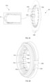
- FIG. 4A schematically shows an assembly diagram of the reset assembly 3 in FIG. 1B , wherein it can be seen that the reset assembly 3 includes: a spring 31 acting axially; a first support gasket 32 for abutting against the end of the spring facing away from the clutch member 2; a second support gasket 33 for abutting against the end of the spring facing the clutch member 2; an end surface bearing 34 for axially supporting the spring so that the spring can also maintain acting axially in the disengaged state of the clutch member.
- the spring 31 is set as a plurality of spiral springs.
- a Belleville spring may also be used instead of a plurality of spiral springs.
- the first support gasket 32 and the second support gasket 33 may be omitted.
- the end surface bearing 34 is axially supported between the second support gasket 33 and the clutch member 2.
- the first support gasket 32 is axially supported on the drive member 1.
- first support gasket 32 is axially supported on the first component 20.
- end surface bearing 34 may also be axially supported between the first support gasket 32 and the drive member 1 or the first component 20.
- the second support gasket 33 is provided with a protrusion 33a stamped from one side, and the protrusion is used to support one end of the spring 31.
- the first support gasket 32 also has the same design here. The support of both ends of the spring 31 is thus achieved effectively at a low cost.
- FIG. 4B schematically shows the end surface bearing 34 in FIG. 4A .
- the end surface bearing 34 includes a first support ring 34b fixedly connected to the second support gasket 33 and a second support ring 34c fixedly connected to the clutch member 2.
- the first support ring 34b is removed from the right figure, and a plurality of cylindrical rollers 34a distributed along a circumferential direction are shown.
- FIGS. 5A to 5C schematically show positional relationships of the pressing assembly 4 when the disconnection module 10 according to the present invention is in the disengaged state, when the disconnection module is switched from the disengaged state to the engaged state, and when the disconnection module is in the engaged state, respectively.
- FIGS. 5A to 5C schematically show positional relationships of the pressing assembly 4 when the disconnection module 10 according to the present invention is in the disengaged state, when the disconnection module is switched from the disengaged state to the engaged state, and when the disconnection module is in the engaged state, respectively.
- the first protrusion 41a marked with a dotted line frame is used as an example to illustrate the working process of the pressing assembly 4.
- the actuator 5 When the disconnection module 10 needs to switch from the disengaged state to the engaged state, referring to FIG. 5B , the actuator 5 is powered on, and the action end 5a is pushed to the left, prompting the second protrusions 42a of the driven plate 42 to push the first protrusions 41a of the pressure plate 41 to move leftwards.
- the second protrusions 42a push the first protrusions 41a out of the first sliding grooves 43a
- the first protrusions 41a are no longer constrained by the first sliding grooves 43a, and the pressure plate 41 can rotate upwards relative to the driven plate 42, and the first inclined surfaces A1 of the first protrusions 41a overlap the inclined surfaces A2 of the first partition portions 43c' above the first sliding grooves 43a.
- the first protrusions 41a rotate upwards and slide rightwards under the pressure applied by the reset assembly 3.
- the actuator 5 is powered off, and the action end 5a retracts rightwards. Since the pressure plate 41 and the driven plate 42 are connected together by a snap mechanism, the rightward sliding of the first protrusions 41a is transmitted to the second protrusions 42a.
- the first protrusions 41a slide through the inclined surfaces A2 of the first partition portions 43c' and continue to slide to the third inclined surfaces A3 assigned to the second sliding grooves 43b.
- the second partition portions 43c" downstream of the second sliding grooves 43b protrude axially from the third inclined surfaces A3 of the second sliding grooves 43b, the first protrusions 41a are stopped on the outside of the second sliding grooves 43b. At this time, the drive member 1 and the clutch member 2 are engaged. Therefore, the disconnection module 10 is in a stable engaged state without additional energy consumption.
- the marked first protrusion 41a moves from the first sliding groove 43a of FIG. 5A (stable disengaged state) to the outside of the second sliding groove 43b of FIG. 5C (stable engaged state).
- the pressure plate 41 rotates at an angle of 360°/ (2 x N) relative to the driven plate 42.
- the marked first protrusion 41a will move from the outside of the second sliding groove 43b of FIG. 5C (stable engaged state) to the first sliding groove 43a downstream (i.e., above the plane of the figure) of the second partition portion 43c" (stable disengaged state), and the pressure plate 41 also rotates at an angle of 360°/ (2 x N) relative to the driven plate 42.
- the disconnection module 10 of the present invention can provide two stable states without consuming additional energy to maintain the current state, thereby reducing energy consumption.
- the power transmission system includes: a motor (not shown) having a drive shaft; a speed reducer (not shown) having at least one transmission shaft; and a disconnection module 10, wherein the first shaft 30 shown includes the drive shaft and the at least one transmission shaft.
- the first component 20 is a gear supported on the first shaft.
- the actuator 5 may be fixed to the housing of the speed reducer.
- the power transmission system refers to a device that is driven by electric power.
- the motor as a drive mechanism, may convert input electrical energy into rotational mechanical energy, and the speed reducer is mechanically connected to the motor, so that the torque and rotational speed generated by the motor are adjusted and further transmitted to the wheels of the vehicle.
- At least one transmission shaft of the speed reducer may include a speed reducer input shaft and an intermediate shaft arranged parallel to each other.
- the speed reducer input shaft may be provided with an input gear.
- the input gear may be integrally formed on the speed reducer input shaft and coaxially arranged with the speed reducer input shaft.
- the intermediate shaft may be provided with an intermediate first gear and an intermediate second gear.
- the intermediate first gear is drivingly meshed with the input gear.
- the intermediate second gear may be drivingly meshed with the driven gear connected to the differential.
- the operation mode of the disconnection module 10 of the present invention in the power transmission system is as follows: One reciprocating movement of the action end 5a brings the disconnection module 10 into a stable engaged state. In the engaged state, the driving force/torque from the motor can be transmitted to the differential and the wheels connected thereto via the first shaft 30, until the next reciprocating movement of the action end 5a switches the disconnection module 10 from the engaged state to a stable disengaged state. In the disengaged state, the transmission of driving force/torque is disconnected, and even if the wheel still drives the auxiliary drive differential to operate, the rotation of the wheel drives as few transmission mechanisms as possible, thereby reducing drag losses.
- a vehicle provided by the present invention includes the power transmission system as described previously.
- the vehicle may be an electrified vehicle, such as a battery electric vehicle (BEV), a hybrid electric vehicle (HEV), a plug-in hybrid electric vehicle (PHEV) or a range-extended electrified vehicle (REEV).
- BEV battery electric vehicle
- HEV hybrid electric vehicle
- PHEV plug-in hybrid electric vehicle
- REEV range-extended electrified vehicle
- the vehicle may also be a hydrogen-powered vehicle. It should be understood that the vehicle of the present invention also has the advantages described above with respect to the disconnection module and the power transmission system.
Landscapes
- Engineering & Computer Science (AREA)
- General Engineering & Computer Science (AREA)
- Mechanical Engineering (AREA)
- Physics & Mathematics (AREA)
- Electromagnetism (AREA)
- Mechanical Operated Clutches (AREA)
Abstract
Description
- The present invention relates to a disconnection module for engaging or disengaging a first component rotatable about a first shaft with or from the first shaft. The present invention further relates to a power transmission system for a vehicle, which comprises the disconnection module. In addition, the present invention also relates to a vehicle, which comprises the power transmission system.
- The trend of designing and manufacturing fuel-efficient and low-emission vehicles has greatly increased, which is inevitably caused by environmental concerns and increased fuel costs. The forefront of this trend is the development of electric vehicles, such as pure electric vehicles, hybrid vehicles, plug-in hybrid vehicles, extended-range electric vehicles, fuel cell vehicles, etc.
- Four-wheel drive electric vehicles are equipped with motors at the front and rear, which are usually divided into main drive motors and auxiliary drive motors, wherein, in some cases, the auxiliary drive motors may be in a non-working state. For example, the auxiliary drive motors are used only during acceleration or special working conditions, or when a driver needs to obtain some high-performance modes. However, when an auxiliary drive motor stops running, the wheel will still drive the auxiliary drive differential to operate, and the differential will drive all transmission mechanisms and motors connected thereto to rotate together, thereby generating drag losses. To improve efficiency, a disconnection module is added to the power transmission system of the electric vehicle, thereby reducing drag losses.
- A conventional disconnection module usually adopts a monostable mode. That is, to realize that the auxiliary drive motors are in a working state, the actuator of the disconnection module needs to remain energized so that the disconnection module is in an engaged state. Therefore, the engaged state is an unstable state, and once the actuator is powered off, the disconnection module cannot maintain the engaged state. This means that the electric vehicle must continue to supply power for the actuator while the auxiliary drive motors are in the working state. Such energy consumption is a waste.
- The technical problem to be solved by the present invention is to overcome the above defects or shortcomings of the prior art, and the present invention provides a disconnection module, which can provide two stable states, namely a stable engaged state and a stable disengaged state, without consuming additional energy to maintain any state.
- According to an aspect of the present invention, provision is made for a disconnection module for engaging or disengaging a first component rotatable about a first shaft with or from a first shaft, wherein the disconnection module comprises:
- a clutch member mounted fixed in rotation on the first shaft;
- a drive member axially arranged between the first component and the clutch member and fixedly connected to the first component, wherein the clutch member can reciprocate axially to engage with and disengage from the drive member, the first shaft rotates together with the first component in an engaged state, and the first shaft is independent of the first component in a disengaged state;
- a reset assembly for applying pressure to the clutch member towards a disengagement direction for disengaging from the drive member;
- an actuator comprising an action end that can reciprocate axially; and
- a pressing assembly configured to connect the action end with the clutch member, so that under the pressure applied by the reset assembly, one reciprocating movement of the action end can bring the clutch member from the disengaged state to the engaged state and maintain the engaged state until a next reciprocating movement of the action end brings the clutch member from the engaged state to the disengaged state.
- In the present invention, the traditional clutch is split into two components, namely, the drive member and the clutch member, wherein the drive member is fixedly connected to the first component, the reset assembly is arranged on the side of the clutch member facing the drive member, and the actuator is arranged on the side of the clutch member away from the drive member. The reset assembly and the actuator cooperate with each other on two sides of the clutch member to provide the clutch member with a force to approach or move away from the drive member. Also, the pressing assembly is arranged between the clutch member and the actuator, so that the clutch member can be in a stable engaged state and a stable disengaged state. That is, it is not necessary to continuously energize the actuator to maintain any of the two states, thereby greatly reducing energy consumption and realizing a bistable disconnection module.
- In an exemplary embodiment, the pressing assembly comprises:
- a pressure plate axially abutting against the clutch member and provided with N first protrusions;
- a driven plate for receiving an action force from the action end and provided with 2 x N second protrusions; and
- a guide member having a first support section radially supporting the driven plate, wherein 2 x N sliding grooves extending axially are provided in the first support section, the sliding grooves are configured to guide the second protrusions to slide axially, and comprise first sliding grooves and second slide grooves having a radial depth smaller than that of the first sliding grooves, and the first sliding grooves are arranged alternately with the second sliding grooves along a circumferential direction,
- wherein in the disengaged state, the first protrusions can enter the first sliding grooves to slide axially, and in the engaged state, the first protrusions can be stopped on the outside of the second sliding grooves.
- In an exemplary embodiment, the first protrusions have first inclined surfaces inclined in the same direction relative to a radial plane, respectively, and the second protrusions have abutting ends for abutting against the first inclined surfaces, respectively; wherein in each reciprocating movement of the action end, when the first protrusions are pushed to the outside of the sliding grooves by the second protrusions, the first protrusions can drive the pressure plate to rotate relative to the driven plate by a certain angle each time under the action force of the action end and the pressure applied by the reset assembly; wherein the guide member is further provided with end inclined surfaces cooperating with the first inclined surfaces of the pressure plate, so that the first protrusions of the pressure plate can move towards the disengagement direction during each rotation, thereby alternately entering the first sliding grooves and being stopped on the outside of the second sliding grooves.
- In an exemplary embodiment, the guide member is provided with partition portions located between the first sliding grooves and the second sliding grooves, and the end inclined surfaces comprise second inclined surfaces assigned to the partition portions and third inclined surfaces assigned to the second sliding grooves, wherein the third inclined surfaces are adjacent to the second inclined surfaces, for example with a smooth transition.
- In an exemplary embodiment, the partition portions comprise first partition portions located upstream of the second sliding grooves along a rotation direction of the pressure plate and second partition portions located downstream of the second sliding groove, and the second partition portions protrude axially from the third inclined surfaces of the second sliding grooves.
- In an exemplary embodiment, the driven plate and/or the pressure plate are/is provided with a snap mechanism for preventing the driven plate from being axially separated from the pressure plate.
- In an exemplary embodiment, the snap mechanism comprises a plurality of claws protruding from one of the driven plate and the pressure plate and capable of being snapped onto an edge of the other of the driven plate and the pressure plate.
- In an exemplary embodiment, the edge is provided with an inclined groove extending obliquely to an axial direction, which is used to mount the claws and prevent the claws from being disengaged axially.
- In an exemplary embodiment, the guide member is sleeved on the first shaft, and the driven plate and the pressure plate are separately sleeved on the guide member.
- In an exemplary embodiment, the partition portions are protrusions.
- In an exemplary embodiment, the guide member further has a second support section for rotationally and fixedly supporting the clutch member, and the second support section is axially spaced apart from the first support section.
- In an exemplary embodiment, the guide member further has a third support section adjacent to the second support section, the disconnection module comprises a retaining ring provided on the third support section, and the retaining ring is arranged on a side of the drive member close to the first component and has an axial gap with the drive member.
- In an exemplary embodiment, the reset assembly comprises:
- a spring acting axially; and
- an end surface bearing for axially supporting the spring so that the spring can also maintain acting axially when the clutch member is in the disengaged state.
- In an exemplary embodiment, the reset assembly further comprises:
- a first support gasket for abutting against an end of the spring facing away from the clutch member; and
- a second support gasket for abutting against an end of the spring facing the clutch member,
- wherein the end surface bearing is axially supported between the second support gasket and the clutch member or axially supported between the first support gasket and the drive member or the first component.
- In an exemplary embodiment, the second support gasket is provided with a protrusion stamped from one side, and the protrusion is used to support one end of the spring.
- In an exemplary embodiment, the end surface bearing comprises a first support ring fixedly connected to the second support gasket and a second support ring fixedly connected to the clutch member.
- In an exemplary embodiment, the first component is an idler gear in a speed reducer, and the drive member is fixedly connected to an end surface of the idler gear.
- According to another aspect of the present invention, provision is made for a power transmission system for a vehicle, comprising: a motor having a drive shaft; a speed reducer having at least one transmission shaft; and the disconnection module described previously, wherein the first shaft comprises the drive shaft or the at least one transmission shaft.
- According to another aspect of the present invention, provision is made for a vehicle, comprising the transmission system described previously.
- With reference to the following description, these and other features, aspects and advantages of the present disclosure will become easier to understand. The accompanying drawings incorporated in this specification and constituting a part thereof illustrate embodiments of the present application, and are used to explain the principles of the present application together with the described description.
- The accompanying drawings are incorporated into and constitute a part of the specification. The accompanying drawings, together with the general description above and the detailed description of exemplary embodiments and methods given below, are used to explain the principles of the present invention. The objects and advantages of the present invention will become apparent when studying the following description according to the accompanying drawings, in which identical elements are given identical or similar reference signs, and in which:
-
FIG. 1A schematically shows an exemplary embodiment of a disconnection module according to the present invention; -
FIG. 1B schematically shows a partial cross-sectional view of the disconnection module ofFIG. 1A ; -
FIG. 2 schematically shows a perspective view of a drive member and a clutch member inFIG. 1A ; -
FIG. 3A schematically shows a guide member of a pressing assembly inFIG. 1A ; -
FIG. 3B schematically shows a pressure plate of the pressing assembly inFIG. 1A ; -
FIG. 3C schematically shows a driven plate of the pressing assembly inFIG. 1A ; -
FIG. 3D schematically shows an assembly diagram of the pressure plate inFIG. 3B and the driven plate inFIG. 3C ; -
FIG. 4A schematically shows an assembly diagram of a reset assembly inFIG. 1B ; -
FIG. 4B schematically shows an end surface bearing inFIG. 3A ; -
FIG. 5A schematically shows a positional relationship of the pressing assembly when the disconnection module according to the present invention is in a disengaged state; -
FIG. 5B schematically shows a positional relationship of the pressing assembly when the disconnection module according to the present invention switches from the disengaged state to an engaged state; and -
FIG. 5C schematically shows a positional relationship of the pressing assembly when the disconnection module according to the present invention is in the engaged state. - Reference will now be made in detail to exemplary embodiments and methods of the present invention shown in the accompanying drawings, in which identical reference signs designate identical or corresponding components. However, it should be noted that the present invention in its broader aspects is not limited to specific details, representative devices and methods, and illustrative examples shown and described in connection with the exemplary embodiments and methods.
- Unless otherwise defined, the technical or scientific terms used herein shall have the common meanings understood by those of ordinary skill in the field to which the present disclosure pertains. The words "first", "second", and the like used in the description and claims of the patent application disclosed herein do not indicate any order, quantity or importance, being merely used to distinguish different component parts. When the number of components is not specified, the number of components may be one or multiple. Similarly, the words "one", "the", "said" and the like do not necessarily indicate a quantity limitation. The words "comprise", "include" and the like mean that an element or object appearing before the word encompasses elements or objects listed after the word and their equivalents, without excluding other elements or objects. "Upper", "lower", "left", "right", etc. are only intended to indicate the relative orientation relationship when a device is used or the orientation relationship shown in the accompanying drawings. When the absolute position of the described object changes, the relative positional relationship may also change accordingly. Unless otherwise explicitly described, the terms "connecting", "connected" and the like refer to a relationship in which the structures are fixed or attached to each other directly or indirectly through an intermediate structures.
- Now refer to the accompanying drawings, in which the same numerals in all of the accompanying drawings represent the same elements.
-
FIG. 1A schematically shows an exemplary embodiment of adisconnection module 10 according to the present invention, andFIG. 1B schematically shows a partial cross-sectional view of thedisconnection module 10 ofFIG. 1A . Here, thedisconnection module 10 is in an engaged state. - The
disconnection module 10 of the present invention may be roughly understood with reference toFIGS. 1A and 1B , wherein thedisconnection module 10 includes: - a
clutch member 2 mounted fixed in rotation on afirst shaft 30; - a
drive member 1 axially arranged between afirst component 20 and theclutch member 2 and fixedly connected to thefirst component 20, wherein theclutch member 2 can reciprocate axially to engage with and disengage from thedrive member 1, thefirst shaft 30 rotates together with thefirst component 20 in an engaged state, and thefirst shaft 30 is independent of thefirst component 20 in a disengaged state; - a
reset assembly 3 for applying pressure to theclutch member 2 towards a disengagement direction for disengaging from thedrive member 1; - an
actuator 5 including anaction end 5a that can reciprocate axially; and - a
pressing assembly 4 configured to connect theaction end 5a with theclutch member 2, so that under the pressure applied by thereset assembly 3, one reciprocating movement of theaction end 5a can bring theclutch member 2 from the disengaged state to the engaged state and maintain the engaged state until a next reciprocating movement of theaction end 5a brings theclutch member 2 from the engaged state to the disengaged state. - In the present invention, the traditional clutch is split into two components, namely, the
drive member 1 and theclutch member 2, wherein thedrive member 1 is fixedly connected to thefirst component 20, thereset assembly 3 is arranged on the side of theclutch member 2 facing thedrive member 1, and theactuator 5 is arranged on the side of theclutch member 2 away from thedrive member 1. Thereset assembly 3 and theactuator 5 cooperate with each other on two sides of the clutch member to provide theclutch member 2 with a force to approach or move away from thedrive member 1. Also, thepressing assembly 3 is arranged between the clutch member and theactuator 5, so that the clutch member can be in a stable engaged state and a stable disengaged state. That is, it is not necessary to continuously energize the actuator to maintain any of the two states, thereby greatly reducing energy consumption and realizing a bistable disconnection module. - It should be noted that "rotatably fixed" described herein means that two components can be connected to rotate together, and their mutual movement in a rotation direction (such as a circumferential direction) is restricted so that they can rotate together. The "rotatably fixed" does not restrict the displacement in a rotation axis direction, so the two rotatably fixed components may have relative displacement in the rotation axis direction. If the displacement in the rotation axis direction is also fixed, it can be considered that the two components are completely fixedly connected.
- It should be noted here that the
first shaft 30 being independent of thefirst component 20 in the disengaged state means that the motion state of thefirst shaft 30 is independent of the motion state of thefirst component 20 at this time. That is, thefirst shaft 30 and thefirst component 20 can rotate independently of each other, but it does not mean that there is no connection between them. - In this exemplary embodiment, the
clutch member 2 and thefirst shaft 30 are rotationally fixed by means of a spline connection, and thedrive member 1 and thefirst component 20 are fixedly connected. -
FIG. 2 shows a perspective view of thedrive member 1 and theclutch member 2 inFIG. 1A . To illustrate the fixed connection manner of thedrive member 1, thefirst component 20 is also shown. Thefirst component 20 is an idler gear in a speed reducer here and has anend surface 21 facing thedrive member 1. Thedrive member 1 is provided with a plurality of transmission pins 1a evenly distributed along a circumferential direction on the side facing thefirst component 20, a plurality ofopenings 21a evenly distributed along the circumferential direction are provided on the end surface of thefirst component 20 facing thedrive member 1, and the transmission pins 1a can mesh with theopenings 21a so that thedrive member 1 is fixedly connected to thefirst component 20. Other connection manners may also be used within the scope of the present invention to achieve a fixed connection between thedrive member 1 and theclutch member 2. - As can be seen from
FIG. 2 , thedrive member 1 has afirst engagement portion 1b, theclutch member 2 has asecond engagement portion 2b, and the first engagement portion can mesh with the second engagement portion. In this exemplary embodiment, thefirst engagement portion 1b and thesecond engagement portion 2b are both configured as end surface teeth. - Referring again to
FIG. 1B , in this exemplary embodiment, thepressing assembly 4 includes aguide member 43, apressure plate 41 and a drivenplate 42. As can be seen, thepressure plate 41 and the drivenplate 42 are both annular and concentrically mounted on theguide member 43, and theguide member 43 is sleeved on thefirst shaft 30. Thepressure plate 41 abuts against theclutch member 2 on the left side, and the drivenplate 42 is used to receive an action force from theaction end 5a of theactuator 5 on the right side and transmit the action force to thepressure plate 41. -
FIGS. 3A to 3C schematically show theguide member 43, thepressure plate 41 and the drivenplate 42 of thepressing assembly 4 inFIG. 1A , respectively.FIG. 3D schematically shows an assembly diagram of thepressure plate 41 and the drivenplate 42. - As can be seen from the left figure in
FIG. 3A , theguide member 43 has afirst support section 43d for radially supporting the drivenplate 42, asecond support section 43e for rotatably and fixedly supporting theclutch member 2, and athird support section 43f adjacent to thesecond support section 43e, wherein thesecond support section 43e is axially spaced from thefirst support section 43d, thereby allowing thepressure plate 41 to move and rotate axially. With this arrangement, theguide member 43 provides support for both the drivenplate 42 and theclutch member 2, and simple assembly can be achieved by providing theintegral guide member 43. - It should be noted that the
guide member 43 may also not include thesecond support section 43e and thethird support section 43f, so that the support of the drivenplate 42 is achieved by a separate member, and the object of the present invention can also be achieved. - A retaining ring 6 (as shown in
FIG. 1B ) may be provided on thethird support section 43f, and the retainingring 6 is arranged on the side of thedrive member 1 close to thefirst component 20, and has an axial gap with thedrive member 1. Thus, thedrive member 1 and theguide member 43 are prevented from being axially disengaged during delivery, so that the disconnection module can be provided as an integral assembly, and the retainingring 6 will not hinder the rotation of thedrive member 1 during the operation of thedisconnection module 10. - The partial area marked by a dotted frame in the left figure of
FIG. 3A is enlarged in the right figure, and the enlarged figure shows that thefirst support section 43d is provided with a plurality ofpartition portions 43c', 43c" extending axially and slidinggrooves grooves 43a and second slidinggrooves 43b having a smaller radial depth than that of the first sliding grooves, and the first slidinggrooves 43a are alternately arranged with the second slidinggrooves 43b along a circumferential direction. In an exemplary embodiment, the first slidinggrooves 43a are set to have the same angular width as the second slidinggrooves 43b, and may also be set to have a different angular width from the second slidinggrooves 43b, both of which can achieve the object of the present invention. - The
guide member 43 is further provided with an end inclined surface, including second inclined surfaces A2 assigned to thepartition portion 43c', 43c" and third inclined surfaces A3 assigned to the second slidinggrooves 43b, wherein the third inclined surfaces A3 are adjacent to the second inclined surfaces A2 with a smooth transition. - As can be seen from
FIG. 3B , thepressure plate 41 is provided with N (here N=9)first protrusions 41a on a radial inner side, thefirst protrusions 41a are evenly distributed along a circumferential direction, and have first inclined surfaces A1 inclined in the same direction relative to a radial plane, respectively, and the slope of the first inclined surfaces A1 is the same as the slope of the second inclined surfaces A2 of thepartition portions 43c', 43c". In addition, thesefirst protrusions 41a have the same angular width as the slidinggrooves - As can be seen from
FIG. 3C , the drivenplate 42 is provided with 2 x Nsecond protrusions 42a on a radial inner side, and thesesecond protrusions 42a are evenly distributed in a circumferential direction and have the same angular width as the slidinggrooves second protrusions 42a are provided with abutting ends B for abutting against the first inclined surfaces A1, respectively. The portion marked with a dotted line frame in the left view is enlarged in the right view. It can be seen from the enlarged view that the abutting end B is set to a tip, so as to form a line contact with the first inclined surface A1 to reduce the friction with the first inclined surface A1. However, the abutting end B may also be designed into other shapes, and the object of the present invention may also be achieved. - The number of sliding
grooves FIG. 3A is 2 x N in total, which is consistent with the number ofsecond protrusions 42a shown inFIG. 3C . The slidinggrooves second protrusions 42a to slide axially. In the disengaged state, thefirst protrusions 41a can enter the first slidinggrooves 43a to slide axially, and in the engaged state, thefirst protrusions 41a can be stopped on the outside of the second slidinggrooves 43b. - In each reciprocating motion of the
action end 5a, when thefirst protrusions 41a are pushed to the outside of the slidinggrooves second protrusions 42a, thefirst protrusions 41a can drive thepressure plate 41 to rotate at certain angles relative to the drivenplate 42 under the action force of theaction end 5a and the pressure applied by thereset assembly 3. The angles may be the same or different depending on whether the angular widths of the first slidinggrooves 43a and the second slidinggrooves 43b are the same. When the angular widths of the first slidinggrooves 43a and the second slidinggrooves 43b are the same, the rotation angles of the pressure plate are the same in two switching processes from the engaged state to the disengaged state and from the disengaged state to the engaged state, with each rotation by 360/(2 x N) degrees. When the angular widths of the first slidinggrooves 43a and the second slidinggrooves 43b are different, the rotation angles of the pressure plate are different in the two switching processes. - Here, the end inclined surfaces A2, A3 of the
guide member 43 cooperate with the first inclined surfaces A1 of the pressure plate, so that thefirst protrusions 41a of the pressure plate can move towards the disengagement direction during each rotation, thereby alternately entering the first slidinggrooves 43a and being stopped on the outside of the second slidinggrooves 43b. - The
partition portion 43c', 43c" of theguide member 43 includefirst partition portions 43c' located upstream of the second slidinggrooves 43b along the rotation direction of thepressure plate 41 andsecond partition portions 43c" located downstream of the second slidinggrooves 43b, and thesecond partition portions 43c" protrudes axially from the third inclined surfaces A3 of the second slidinggrooves 43b. Thus, the first protrusions of the pressure plate can be stopped on the outside of the second slidinggrooves 43b when rotating from thefirst partition portions 43c' toward thesecond partition portions 43c". - In this exemplary embodiment, the driven
plate 42 is provided with a snap mechanism for preventing the drivenplate 42 from being axially separated from thepressure plate 41. In another exemplary embodiment, the snap mechanism may also be provided on thepressure plate 41. The object of the present invention can also be achieved. - As can be seen from
FIG. 3C , the snap mechanism includes a plurality ofclaws 42b protruding from the drivenplate 42 and capable of being snapped on an edge of thepressure plate 41. Aninclined groove 41b extending obliquely to an axial direction is provided on an edge of thepressure plate 41 for mounting theclaws 42b and preventing the claws from being disengaged axially. - As can be seen from
FIG. 3D , the first inclined surfaces A1 (seeFIG. 3B ) of thefirst protrusions 41a of thepressure plate 41 abut against the abutting ends B (seeFIG. 3C ) of thesecond protrusions 42a of the drivenplate 42. In addition, it can be seen that theclaws 42b are snapped on the edge of thepressure plate 41 to prevent the drivenplate 42 from being axially separated from thepressure plate 41. Theclaws 42b may be rotated obliquely into theinclined grooves 41b when mounting and snapped outside the inclined grooves. Due to the design of the inclined grooves, theclaws 42b can be prevented from being axially disengaged during use. - In another exemplary embodiment, as an alternative to the
inclined grooves 41b, circumferential ridges may be provided on the edge of thepressure plate 41, so that theclaws 42b can be mounted on the circumferential ridges by radial elastic deformation, but are not easily disengaged axially after mounting. The object of the present invention can also be achieved. - In this exemplary embodiment, for example, with reference to
FIGS. 1B and3A-3D , it can be seen that theguide member 43 is sleeved on thefirst shaft 30, the drivenplate 42 and thepressure plate 41 are separately sleeved on theguide member 43, and thepartition portions 43c', 43c" are protrusions, exactly, protrusions protruding radially outwards. Correspondingly, thefirst protrusions 41a of thepressure plate 41 and thesecond protrusions 42a of the drivenplate 42 are all protrusions protruding radially inwards. - In another exemplary embodiment, the guide member may also be sleeved on the driven plate. In this case, 2 x N sliding grooves may be provided in a circumferential wall of the guide member, wherein deeper first sliding grooves may pass through the circumferential wall of the guide member so that they can be seen from the outside of the guide member, whereas shallower second sliding grooves cannot be seen from the outside of the guide member. Correspondingly, the first protrusions of the pressure plate and the second protrusions of the driven plate should be protrusions protruding radially outwards.
-
FIG. 4A schematically shows an assembly diagram of thereset assembly 3 inFIG. 1B , wherein it can be seen that thereset assembly 3 includes: aspring 31 acting axially; afirst support gasket 32 for abutting against the end of the spring facing away from theclutch member 2; asecond support gasket 33 for abutting against the end of the spring facing theclutch member 2; an end surface bearing 34 for axially supporting the spring so that the spring can also maintain acting axially in the disengaged state of the clutch member. - Here, the
spring 31 is set as a plurality of spiral springs. In another exemplary embodiment, for example, a Belleville spring may also be used instead of a plurality of spiral springs. In this case, thefirst support gasket 32 and thesecond support gasket 33 may be omitted. - In
FIG. 4A , the end surface bearing 34 is axially supported between thesecond support gasket 33 and theclutch member 2. Thefirst support gasket 32 is axially supported on thedrive member 1. - In another exemplary embodiment, it can also be contemplated that the
first support gasket 32 is axially supported on thefirst component 20. In another exemplary embodiment, the end surface bearing 34 may also be axially supported between thefirst support gasket 32 and thedrive member 1 or thefirst component 20. - It can also be seen from
FIG. 4A that thesecond support gasket 33 is provided with aprotrusion 33a stamped from one side, and the protrusion is used to support one end of thespring 31. Thefirst support gasket 32 also has the same design here. The support of both ends of thespring 31 is thus achieved effectively at a low cost. -
FIG. 4B schematically shows the end surface bearing 34 inFIG. 4A . As can be seen from the left figure, the end surface bearing 34 includes afirst support ring 34b fixedly connected to thesecond support gasket 33 and asecond support ring 34c fixedly connected to theclutch member 2. Thefirst support ring 34b is removed from the right figure, and a plurality ofcylindrical rollers 34a distributed along a circumferential direction are shown. -
FIGS. 5A to 5C schematically show positional relationships of thepressing assembly 4 when thedisconnection module 10 according to the present invention is in the disengaged state, when the disconnection module is switched from the disengaged state to the engaged state, and when the disconnection module is in the engaged state, respectively. For clarity, only the positions of thefirst protrusions 41a of thepressure plate 41 and thesecond protrusions 42a of the drivenplate 42 on theguide member 43 are shown. Here, thefirst protrusion 41a marked with a dotted line frame is used as an example to illustrate the working process of thepressing assembly 4. - In the disengaged state shown in
FIG. 5A , thefirst protrusions 41a of thepressure plate 41 and thesecond protrusions 42a of the drivenplate 42 all enter the deeper first slidinggrooves 43a (see the left figure). At this time, theactuator 5 is powered off, and theaction end 5a (which cannot be seen here) is retracted, so it does not abut against the drivenplate 42. The drivenplate 42 is prevented from being separated from thepressure plate 41 by theclaws 42b being snapped on the edge of the pressure plate 41 (see the right figure). At this time, thedrive member 1 and theclutch member 2 are disengaged. Therefore, thedisconnection module 10 is in a stable disengaged state without additional energy consumption. - When the
disconnection module 10 needs to switch from the disengaged state to the engaged state, referring toFIG. 5B , theactuator 5 is powered on, and theaction end 5a is pushed to the left, prompting thesecond protrusions 42a of the drivenplate 42 to push thefirst protrusions 41a of thepressure plate 41 to move leftwards. When thesecond protrusions 42a push thefirst protrusions 41a out of the first slidinggrooves 43a, thefirst protrusions 41a are no longer constrained by the first slidinggrooves 43a, and thepressure plate 41 can rotate upwards relative to the drivenplate 42, and the first inclined surfaces A1 of thefirst protrusions 41a overlap the inclined surfaces A2 of thefirst partition portions 43c' above the first slidinggrooves 43a. At this time, thefirst protrusions 41a rotate upwards and slide rightwards under the pressure applied by thereset assembly 3. - During this period, the
actuator 5 is powered off, and theaction end 5a retracts rightwards. Since thepressure plate 41 and the drivenplate 42 are connected together by a snap mechanism, the rightward sliding of thefirst protrusions 41a is transmitted to thesecond protrusions 42a. Thefirst protrusions 41a slide through the inclined surfaces A2 of thefirst partition portions 43c' and continue to slide to the third inclined surfaces A3 assigned to the second slidinggrooves 43b. As shown inFIG. 5C , since thesecond partition portions 43c" downstream of the second slidinggrooves 43b protrude axially from the third inclined surfaces A3 of the second slidinggrooves 43b, thefirst protrusions 41a are stopped on the outside of the second slidinggrooves 43b. At this time, thedrive member 1 and theclutch member 2 are engaged. Therefore, thedisconnection module 10 is in a stable engaged state without additional energy consumption. - Therefore, in one reciprocating motion of the
action end 5a, the markedfirst protrusion 41a moves from the first slidinggroove 43a ofFIG. 5A (stable disengaged state) to the outside of the second slidinggroove 43b ofFIG. 5C (stable engaged state). Thepressure plate 41 rotates at an angle of 360°/ (2 x N) relative to the drivenplate 42. - Accordingly, in the next reciprocating motion of the
action end 5a, the markedfirst protrusion 41a will move from the outside of the second slidinggroove 43b ofFIG. 5C (stable engaged state) to the first slidinggroove 43a downstream (i.e., above the plane of the figure) of thesecond partition portion 43c" (stable disengaged state), and thepressure plate 41 also rotates at an angle of 360°/ (2 x N) relative to the drivenplate 42. - It can thus be seen that the
disconnection module 10 of the present invention can provide two stable states without consuming additional energy to maintain the current state, thereby reducing energy consumption. - The power transmission system provided by the present invention includes: a motor (not shown) having a drive shaft; a speed reducer (not shown) having at least one transmission shaft; and a
disconnection module 10, wherein thefirst shaft 30 shown includes the drive shaft and the at least one transmission shaft. Thefirst component 20 is a gear supported on the first shaft. Theactuator 5 may be fixed to the housing of the speed reducer. - It should be understood that the power transmission system refers to a device that is driven by electric power. Illustratively, the motor, as a drive mechanism, may convert input electrical energy into rotational mechanical energy, and the speed reducer is mechanically connected to the motor, so that the torque and rotational speed generated by the motor are adjusted and further transmitted to the wheels of the vehicle.
- At least one transmission shaft of the speed reducer may include a speed reducer input shaft and an intermediate shaft arranged parallel to each other. The speed reducer input shaft may be provided with an input gear. The input gear may be integrally formed on the speed reducer input shaft and coaxially arranged with the speed reducer input shaft. The intermediate shaft may be provided with an intermediate first gear and an intermediate second gear. The intermediate first gear is drivingly meshed with the input gear. The intermediate second gear may be drivingly meshed with the driven gear connected to the differential. Thus, a two-stage helical gear parallel shaft speed reducer arrangement from the speed reducer input shaft to the differential is realized.
- The operation mode of the
disconnection module 10 of the present invention in the power transmission system is as follows: One reciprocating movement of theaction end 5a brings thedisconnection module 10 into a stable engaged state. In the engaged state, the driving force/torque from the motor can be transmitted to the differential and the wheels connected thereto via thefirst shaft 30, until the next reciprocating movement of theaction end 5a switches thedisconnection module 10 from the engaged state to a stable disengaged state. In the disengaged state, the transmission of driving force/torque is disconnected, and even if the wheel still drives the auxiliary drive differential to operate, the rotation of the wheel drives as few transmission mechanisms as possible, thereby reducing drag losses. - A vehicle provided by the present invention includes the power transmission system as described previously. The vehicle may be an electrified vehicle, such as a battery electric vehicle (BEV), a hybrid electric vehicle (HEV), a plug-in hybrid electric vehicle (PHEV) or a range-extended electrified vehicle (REEV). The vehicle may also be a hydrogen-powered vehicle. It should be understood that the vehicle of the present invention also has the advantages described above with respect to the disconnection module and the power transmission system.
- Although exemplary embodiments are described in the foregoing description, it should be noted that a large number of variants are possible. In addition, it should be noted that the exemplary embodiments are merely examples and should not be considered as any form of limitation on the scope of protection, applicability, and device construction according to the exemplary embodiments. More precisely, the summary and the description of embodiments are to provide professionals with guidance for implementing at least one exemplary embodiment, wherein various modifications can be made in terms of the function and layout of the assembly, as long as they do not deviate from the scope of protection determined by the claims and equivalent feature combinations.
Claims (15)
- Disconnection module (10) for engaging or disengaging a first component (20) rotatable about a first shaft (30) with or from a first shaft (30), wherein the disconnection module (10) comprises:a clutch member (2) mounted fixed in rotation on the first shaft (30);a drive member (1) axially arranged between the first component (20) and the clutch member (2) and fixedly connected to the first component (20), wherein the clutch member (2) can reciprocate axially to engage with and disengage from the drive member (1), the first shaft (30) rotates together with the first component (20) in an engaged state, and the first shaft (30) is independent of the first component (20) in a disengaged state;a reset assembly (3) for applying pressure to the clutch member (2) towards a disengagement direction for disengaging from the drive member (1);an actuator (5) comprising an action end (5a) that can reciprocate axially; anda pressing assembly (4) configured to connect the action end (5a) with the clutch member (2), so that under the pressure applied by the reset assembly (3), one reciprocating movement of the action end (5a) can bring the clutch member (2) from the disengaged state to the engaged state and maintain the engaged state until a next reciprocating movement of the action end (5a) brings the clutch member (2) from the engaged state to the disengaged state.
- Disconnection module (10) according to Claim 1, wherein the pressing assembly (4) comprises:a pressure plate (41) axially abutting against the clutch member (2) and provided with N first protrusions (41a);a driven plate (42) for receiving an action force from the action end (5a) and provided with 2 x N second protrusions (42a); anda guide member (43) having a first support section (43d) radially supporting the driven plate (42), wherein 2 x N sliding grooves (43a, 43b) extending axially are provided in the first support section, the sliding grooves are configured to guide the second protrusions (42a) to slide axially, and comprise first sliding grooves (43a) and second slide grooves (43b) having a radial depth smaller than that of the first sliding grooves, and the first sliding grooves are arranged alternately with the second sliding grooves along a circumferential direction,wherein in the disengaged state, the first protrusions (41a) can enter the first sliding grooves (43a) to slide axially, and in the engaged state, the first protrusions (41a) can be stopped on the outside of the second sliding grooves (43b).
- Disconnection module (10) according to Claim 2, wherein the first protrusions (41a) have first inclined surfaces (A1) inclined in the same direction relative to a radial plane, respectively, and the second protrusions (42a) have abutting ends (B) for abutting against the first inclined surfaces, respectively; wherein in each reciprocating movement of the action end, when the first protrusions (41a) are pushed to the outside of the sliding grooves by the second protrusions (42a), the first protrusions (41a) can drive the pressure plate (41) to rotate relative to the driven plate (42) by a certain angle each time under the action force of the action end (5a) and the pressure applied by the reset assembly (3);
wherein the guide member (43) is further provided with end inclined surfaces (A2, A3) cooperating with the first inclined surfaces (A1) of the pressure plate, so that the first protrusions (41a) of the pressure plate (41) can move towards the disengagement direction during each rotation, thereby alternately entering the first sliding grooves (43a) and being stopped on the outside of the second sliding grooves (43b). - Disconnection module (10) according to Claim 3, wherein the guide member (43) is provided with partition portions (43c', 43c") located between the first sliding grooves (43a) and the second sliding grooves (43b), and the end inclined surfaces comprise second inclined surfaces (A2) assigned to the partition portions and third inclined surfaces (A3) assigned to the second sliding grooves (43b), wherein the third inclined surfaces are adjacent to the second inclined surfaces.
- Disconnection module (10) according to Claim 4, wherein the partition portions comprise first partition portions (43c') located upstream of the second sliding grooves (43b) along a rotation direction of the pressure plate (41) and second partition portions (43c") located downstream of the second sliding groove (43b), and the second partition portions protrude axially from the third inclined surfaces (A3) of the second sliding grooves (43b).
- Disconnection module (10) according to Claim 2, wherein the driven plate (42) and/or the pressure plate (41) are/is provided with a snap mechanism for preventing the driven plate (42) from being axially separated from the pressure plate (41).
- Disconnection module (10) according to Claim 6, wherein the snap mechanism comprises a plurality of claws (42b) protruding from one of the driven plate (42) and the pressure plate (41) and capable of being snapped onto an edge of the other of the driven plate (42) and the pressure plate (41).
- Disconnection module (10) according to Claim 7, wherein the edge is provided with an inclined groove (41b) extending obliquely to an axial direction, which is used to mount the claws (42b) and prevent the claws from being disengaged axially.
- Disconnection module (10) according to any one of Claims 2 to 8, wherein the guide member (43) is sleeved on the first shaft (30), and the driven plate (42) and the pressure plate (41) are separately sleeved on the guide member.
- Disconnection module (10) according to any one of Claims 2 to 8, wherein the guide member (43) further has a second support section (43e) for rotationally and fixedly supporting the clutch member (2), and the second support section is axially spaced apart from the first support section (43d).
- Disconnection module (10) according to Claim 10, wherein the guide member (43) further has a third support section (43f) adjacent to the second support section (43e), the disconnection module (10) comprises a retaining ring (6) provided on the third support section, and the retaining ring is arranged on a side of the drive member (1) close to the first component (20) and has an axial gap with the drive member (1).
- Disconnection module (10) according to Claim 1, wherein the reset assembly (3) comprises:a spring (31) acting axially; andan end surface bearing (34) for axially supporting the spring (31), so that the spring can also maintain acting axially when the clutch member (2) is in the disengaged state.
- Disconnection module (10) according to Claim 12, wherein the reset assembly (3) further comprises:a first support gasket (32) for abutting against an end of the spring (31) facing away from the clutch member (2); anda second support gasket (33) for abutting against an end of the spring (31) facing the clutch member (2),wherein the end surface bearing (34) is axially supported between the second support gasket (33) and the clutch member (2) or axially supported between the first support gasket (32) and the drive member (1) or the first component (20).
- Disconnection module (10) according to Claim 1, wherein the first component (20) is an idler gear in a speed reducer, and the drive member (1) is fixedly connected to an end surface of the idler gear.
- Power transmission system for a vehicle, comprising:a motor having a drive shaft;a speed reducer having at least one transmission shaft; andthe disconnection module (10) according to any one of Claims 1 to 14, wherein the first shaft (30) comprises the drive shaft or the at least one transmission shaft.
Applications Claiming Priority (1)
| Application Number | Priority Date | Filing Date | Title |
|---|---|---|---|
| CN202311125341.7A CN119554339A (en) | 2023-09-01 | 2023-09-01 | Disconnect the module, the vehicle's powertrain, and the vehicle |
Publications (1)
| Publication Number | Publication Date |
|---|---|
| EP4520988A1 true EP4520988A1 (en) | 2025-03-12 |
Family
ID=92626454
Family Applications (1)
| Application Number | Title | Priority Date | Filing Date |
|---|---|---|---|
| EP24197316.3A Pending EP4520988A1 (en) | 2023-09-01 | 2024-08-29 | Disconnection module, power transmission system for vehicle, and vehicle |
Country Status (3)
| Country | Link |
|---|---|
| US (1) | US12523261B2 (en) |
| EP (1) | EP4520988A1 (en) |
| CN (1) | CN119554339A (en) |
Citations (3)
| Publication number | Priority date | Publication date | Assignee | Title |
|---|---|---|---|---|
| CN212803996U (en) * | 2020-05-21 | 2021-03-26 | 威睿电动汽车技术(宁波)有限公司 | An electric reducer disconnecting mechanism and a transmission using the same |
| EP3538784B1 (en) * | 2016-11-14 | 2021-04-07 | GKN Driveline Bruneck AG | Clutch assembly and drive assembly |
| CN220816339U (en) * | 2023-09-01 | 2024-04-19 | 法雷奥离合器公司 | Disconnect module, power transmission system of vehicle and vehicle |
Family Cites Families (8)
| Publication number | Priority date | Publication date | Assignee | Title |
|---|---|---|---|---|
| CN209324887U (en) * | 2015-08-10 | 2019-08-30 | Gkn 动力传动系统北美有限公司 | Automotive powertrain components and all-wheel drive automotive powertrains |
| WO2017075180A1 (en) * | 2015-10-27 | 2017-05-04 | Dana Automotive Systems Group, Llc | Driveline rapid disconnect apparatus |
| JP6502443B2 (en) | 2017-09-01 | 2019-04-17 | 株式会社エフ・シー・シー | Power transmission |
| JP7149827B2 (en) | 2018-12-05 | 2022-10-07 | 株式会社エフ・シー・シー | power transmission device |
| DE102019133670B3 (en) * | 2019-12-10 | 2021-05-12 | Audi Ag | Drive device |
| CN112503108B (en) | 2020-12-31 | 2025-10-31 | 温岭市华鑫机械制造有限公司 | Intermediate shaft clutch mechanism |
| US11739838B2 (en) * | 2021-06-02 | 2023-08-29 | Dana Graziano S.R.L. | Park lock with dog clutch and ball ramp |
| CN115853921A (en) | 2022-12-08 | 2023-03-28 | 中国第一汽车股份有限公司 | Power system and vehicle with same |
-
2023
- 2023-09-01 CN CN202311125341.7A patent/CN119554339A/en active Pending
-
2024
- 2024-08-29 EP EP24197316.3A patent/EP4520988A1/en active Pending
- 2024-08-29 US US18/818,699 patent/US12523261B2/en active Active
Patent Citations (3)
| Publication number | Priority date | Publication date | Assignee | Title |
|---|---|---|---|---|
| EP3538784B1 (en) * | 2016-11-14 | 2021-04-07 | GKN Driveline Bruneck AG | Clutch assembly and drive assembly |
| CN212803996U (en) * | 2020-05-21 | 2021-03-26 | 威睿电动汽车技术(宁波)有限公司 | An electric reducer disconnecting mechanism and a transmission using the same |
| CN220816339U (en) * | 2023-09-01 | 2024-04-19 | 法雷奥离合器公司 | Disconnect module, power transmission system of vehicle and vehicle |
Also Published As
| Publication number | Publication date |
|---|---|
| US12523261B2 (en) | 2026-01-13 |
| CN119554339A (en) | 2025-03-04 |
| US20250075747A1 (en) | 2025-03-06 |
Similar Documents
| Publication | Publication Date | Title |
|---|---|---|
| US12092172B2 (en) | Controllable clutch assembly | |
| US9328782B2 (en) | Two-way clutch | |
| CN112503157B (en) | Differential with electromagnetic thrust clutch function | |
| CN221033704U (en) | Electromagnetic tooth clutch device of electric vehicle, transmission connection device and electric vehicle | |
| EP4520988A1 (en) | Disconnection module, power transmission system for vehicle, and vehicle | |
| EP1350657B1 (en) | Power switching apparatus for switching between two-wheel and four-wheel drive states | |
| CN214305134U (en) | Differential mechanism with electromagnetic thrust clutch function | |
| CN113383176B (en) | Friction engagement device | |
| CN220816339U (en) | Disconnect module, power transmission system of vehicle and vehicle | |
| EP4215774A1 (en) | Drive transmission device for vehicle | |
| CN114857233A (en) | Locking differential mechanism | |
| EP1350660B1 (en) | Power switching apparatus | |
| CN217705485U (en) | Power system and vehicle | |
| CN218326150U (en) | Electromagnetic control reverse gear shift speed reducer power assembly | |
| CN219706670U (en) | P2 hybrid electric vehicle driving system adopting multimode clutch | |
| EP4520989A1 (en) | Disconnect module, power transmission system for vehicle, and vehicle | |
| WO2015071736A2 (en) | Engagement apparatus and hybrid vehicle drive system | |
| CN217029728U (en) | Clutch mechanism and vehicle | |
| EP4520990A1 (en) | Disconnect module, power transmission system for a vehicle, synchronization mechanism for a vehicle and vehicle technical field | |
| JP2000346103A (en) | Rotation transmission device | |
| KR101284253B1 (en) | Double clutch actuator | |
| CN113108052A (en) | Actuator of transfer case | |
| CN223578750U (en) | Differential mechanism and vehicle | |
| WO2025163193A1 (en) | Disconnection module, power transmission system for vehicle, and vehicle | |
| CN223725221U (en) | Clutch and working machine |
Legal Events
| Date | Code | Title | Description |
|---|---|---|---|
| PUAI | Public reference made under article 153(3) epc to a published international application that has entered the european phase |
Free format text: ORIGINAL CODE: 0009012 |
|
| STAA | Information on the status of an ep patent application or granted ep patent |
Free format text: STATUS: REQUEST FOR EXAMINATION WAS MADE |
|
| 17P | Request for examination filed |
Effective date: 20240829 |
|
| AK | Designated contracting states |
Kind code of ref document: A1 Designated state(s): AL AT BE BG CH CY CZ DE DK EE ES FI FR GB GR HR HU IE IS IT LI LT LU LV MC ME MK MT NL NO PL PT RO RS SE SI SK SM TR |
|
| GRAP | Despatch of communication of intention to grant a patent |
Free format text: ORIGINAL CODE: EPIDOSNIGR1 |
|
| STAA | Information on the status of an ep patent application or granted ep patent |
Free format text: STATUS: GRANT OF PATENT IS INTENDED |
|
| RIC1 | Information provided on ipc code assigned before grant |
Ipc: F16D 11/14 20060101AFI20251222BHEP Ipc: F16D 27/118 20060101ALI20251222BHEP Ipc: F16D 23/12 20060101ALI20251222BHEP |
|
| INTG | Intention to grant announced |
Effective date: 20260122 |
|
| RIN1 | Information on inventor provided before grant (corrected) |
Inventor name: HU, XUN Inventor name: HE, FEI Inventor name: LI, LU Inventor name: LI, CHUN Inventor name: SHI, LEI Inventor name: HAN, YEFEI |