EP4520902A1 - Vehicle door opening and closing device and vehicle - Google Patents
Vehicle door opening and closing device and vehicle Download PDFInfo
- Publication number
- EP4520902A1 EP4520902A1 EP23819019.3A EP23819019A EP4520902A1 EP 4520902 A1 EP4520902 A1 EP 4520902A1 EP 23819019 A EP23819019 A EP 23819019A EP 4520902 A1 EP4520902 A1 EP 4520902A1
- Authority
- EP
- European Patent Office
- Prior art keywords
- vehicle door
- guide rail
- driven
- arm
- vehicle
- Prior art date
- Legal status (The legal status is an assumption and is not a legal conclusion. Google has not performed a legal analysis and makes no representation as to the accuracy of the status listed.)
- Pending
Links
Images

Classifications
-
- E—FIXED CONSTRUCTIONS
- E05—LOCKS; KEYS; WINDOW OR DOOR FITTINGS; SAFES
- E05D—HINGES OR SUSPENSION DEVICES FOR DOORS, WINDOWS OR WINGS
- E05D15/00—Suspension arrangements for wings
- E05D15/56—Suspension arrangements for wings with successive different movements
- E05D15/58—Suspension arrangements for wings with successive different movements with both swinging and sliding movements
-
- E—FIXED CONSTRUCTIONS
- E05—LOCKS; KEYS; WINDOW OR DOOR FITTINGS; SAFES
- E05D—HINGES OR SUSPENSION DEVICES FOR DOORS, WINDOWS OR WINGS
- E05D15/00—Suspension arrangements for wings
- E05D15/06—Suspension arrangements for wings for wings sliding horizontally more or less in their own plane
- E05D15/10—Suspension arrangements for wings for wings sliding horizontally more or less in their own plane movable out of one plane into a second parallel plane
- E05D15/1005—Suspension arrangements for wings for wings sliding horizontally more or less in their own plane movable out of one plane into a second parallel plane the wing being supported on arms movable in horizontal planes
- E05D15/101—Suspension arrangements for wings for wings sliding horizontally more or less in their own plane movable out of one plane into a second parallel plane the wing being supported on arms movable in horizontal planes specially adapted for vehicles
-
- E—FIXED CONSTRUCTIONS
- E05—LOCKS; KEYS; WINDOW OR DOOR FITTINGS; SAFES
- E05D—HINGES OR SUSPENSION DEVICES FOR DOORS, WINDOWS OR WINGS
- E05D15/00—Suspension arrangements for wings
- E05D15/28—Suspension arrangements for wings supported on arms movable in horizontal plane
-
- E—FIXED CONSTRUCTIONS
- E05—LOCKS; KEYS; WINDOW OR DOOR FITTINGS; SAFES
- E05D—HINGES OR SUSPENSION DEVICES FOR DOORS, WINDOWS OR WINGS
- E05D15/00—Suspension arrangements for wings
- E05D15/28—Suspension arrangements for wings supported on arms movable in horizontal plane
- E05D15/30—Suspension arrangements for wings supported on arms movable in horizontal plane with pivoted arms and sliding guides
-
- E—FIXED CONSTRUCTIONS
- E05—LOCKS; KEYS; WINDOW OR DOOR FITTINGS; SAFES
- E05F—DEVICES FOR MOVING WINGS INTO OPEN OR CLOSED POSITION; CHECKS FOR WINGS; WING FITTINGS NOT OTHERWISE PROVIDED FOR, CONCERNED WITH THE FUNCTIONING OF THE WING
- E05F15/00—Power-operated mechanisms for wings
- E05F15/60—Power-operated mechanisms for wings using electrical actuators
- E05F15/603—Power-operated mechanisms for wings using electrical actuators using rotary electromotors
- E05F15/611—Power-operated mechanisms for wings using electrical actuators using rotary electromotors for swinging wings
- E05F15/63—Power-operated mechanisms for wings using electrical actuators using rotary electromotors for swinging wings operated by swinging arms
-
- E—FIXED CONSTRUCTIONS
- E05—LOCKS; KEYS; WINDOW OR DOOR FITTINGS; SAFES
- E05F—DEVICES FOR MOVING WINGS INTO OPEN OR CLOSED POSITION; CHECKS FOR WINGS; WING FITTINGS NOT OTHERWISE PROVIDED FOR, CONCERNED WITH THE FUNCTIONING OF THE WING
- E05F15/00—Power-operated mechanisms for wings
- E05F15/60—Power-operated mechanisms for wings using electrical actuators
- E05F15/603—Power-operated mechanisms for wings using electrical actuators using rotary electromotors
- E05F15/611—Power-operated mechanisms for wings using electrical actuators using rotary electromotors for swinging wings
- E05F15/63—Power-operated mechanisms for wings using electrical actuators using rotary electromotors for swinging wings operated by swinging arms
- E05F2015/631—Power-operated mechanisms for wings using electrical actuators using rotary electromotors for swinging wings operated by swinging arms the end of the arm sliding in a track; Slider arms therefor
-
- E—FIXED CONSTRUCTIONS
- E05—LOCKS; KEYS; WINDOW OR DOOR FITTINGS; SAFES
- E05Y—INDEXING SCHEME ASSOCIATED WITH SUBCLASSES E05D AND E05F, RELATING TO CONSTRUCTION ELEMENTS, ELECTRIC CONTROL, POWER SUPPLY, POWER SIGNAL OR TRANSMISSION, USER INTERFACES, MOUNTING OR COUPLING, DETAILS, ACCESSORIES, AUXILIARY OPERATIONS NOT OTHERWISE PROVIDED FOR, APPLICATION THEREOF
- E05Y2201/00—Constructional elements; Accessories therefor
- E05Y2201/40—Motors; Magnets; Springs; Weights; Accessories therefor
- E05Y2201/43—Motors
- E05Y2201/434—Electromotors; Details thereof
-
- E—FIXED CONSTRUCTIONS
- E05—LOCKS; KEYS; WINDOW OR DOOR FITTINGS; SAFES
- E05Y—INDEXING SCHEME ASSOCIATED WITH SUBCLASSES E05D AND E05F, RELATING TO CONSTRUCTION ELEMENTS, ELECTRIC CONTROL, POWER SUPPLY, POWER SIGNAL OR TRANSMISSION, USER INTERFACES, MOUNTING OR COUPLING, DETAILS, ACCESSORIES, AUXILIARY OPERATIONS NOT OTHERWISE PROVIDED FOR, APPLICATION THEREOF
- E05Y2201/00—Constructional elements; Accessories therefor
- E05Y2201/60—Suspension or transmission members; Accessories therefor
- E05Y2201/622—Suspension or transmission members elements
- E05Y2201/624—Arms
-
- E—FIXED CONSTRUCTIONS
- E05—LOCKS; KEYS; WINDOW OR DOOR FITTINGS; SAFES
- E05Y—INDEXING SCHEME ASSOCIATED WITH SUBCLASSES E05D AND E05F, RELATING TO CONSTRUCTION ELEMENTS, ELECTRIC CONTROL, POWER SUPPLY, POWER SIGNAL OR TRANSMISSION, USER INTERFACES, MOUNTING OR COUPLING, DETAILS, ACCESSORIES, AUXILIARY OPERATIONS NOT OTHERWISE PROVIDED FOR, APPLICATION THEREOF
- E05Y2201/00—Constructional elements; Accessories therefor
- E05Y2201/60—Suspension or transmission members; Accessories therefor
- E05Y2201/622—Suspension or transmission members elements
- E05Y2201/624—Arms
- E05Y2201/626—Levers
-
- E—FIXED CONSTRUCTIONS
- E05—LOCKS; KEYS; WINDOW OR DOOR FITTINGS; SAFES
- E05Y—INDEXING SCHEME ASSOCIATED WITH SUBCLASSES E05D AND E05F, RELATING TO CONSTRUCTION ELEMENTS, ELECTRIC CONTROL, POWER SUPPLY, POWER SIGNAL OR TRANSMISSION, USER INTERFACES, MOUNTING OR COUPLING, DETAILS, ACCESSORIES, AUXILIARY OPERATIONS NOT OTHERWISE PROVIDED FOR, APPLICATION THEREOF
- E05Y2201/00—Constructional elements; Accessories therefor
- E05Y2201/60—Suspension or transmission members; Accessories therefor
- E05Y2201/622—Suspension or transmission members elements
- E05Y2201/638—Cams; Ramps
-
- E—FIXED CONSTRUCTIONS
- E05—LOCKS; KEYS; WINDOW OR DOOR FITTINGS; SAFES
- E05Y—INDEXING SCHEME ASSOCIATED WITH SUBCLASSES E05D AND E05F, RELATING TO CONSTRUCTION ELEMENTS, ELECTRIC CONTROL, POWER SUPPLY, POWER SIGNAL OR TRANSMISSION, USER INTERFACES, MOUNTING OR COUPLING, DETAILS, ACCESSORIES, AUXILIARY OPERATIONS NOT OTHERWISE PROVIDED FOR, APPLICATION THEREOF
- E05Y2201/00—Constructional elements; Accessories therefor
- E05Y2201/60—Suspension or transmission members; Accessories therefor
- E05Y2201/622—Suspension or transmission members elements
- E05Y2201/682—Pins
-
- E—FIXED CONSTRUCTIONS
- E05—LOCKS; KEYS; WINDOW OR DOOR FITTINGS; SAFES
- E05Y—INDEXING SCHEME ASSOCIATED WITH SUBCLASSES E05D AND E05F, RELATING TO CONSTRUCTION ELEMENTS, ELECTRIC CONTROL, POWER SUPPLY, POWER SIGNAL OR TRANSMISSION, USER INTERFACES, MOUNTING OR COUPLING, DETAILS, ACCESSORIES, AUXILIARY OPERATIONS NOT OTHERWISE PROVIDED FOR, APPLICATION THEREOF
- E05Y2201/00—Constructional elements; Accessories therefor
- E05Y2201/60—Suspension or transmission members; Accessories therefor
- E05Y2201/622—Suspension or transmission members elements
- E05Y2201/686—Rods, links
-
- E—FIXED CONSTRUCTIONS
- E05—LOCKS; KEYS; WINDOW OR DOOR FITTINGS; SAFES
- E05Y—INDEXING SCHEME ASSOCIATED WITH SUBCLASSES E05D AND E05F, RELATING TO CONSTRUCTION ELEMENTS, ELECTRIC CONTROL, POWER SUPPLY, POWER SIGNAL OR TRANSMISSION, USER INTERFACES, MOUNTING OR COUPLING, DETAILS, ACCESSORIES, AUXILIARY OPERATIONS NOT OTHERWISE PROVIDED FOR, APPLICATION THEREOF
- E05Y2800/00—Details, accessories and auxiliary operations not otherwise provided for
- E05Y2800/26—Form or shape
- E05Y2800/266—Form or shape curved
-
- E—FIXED CONSTRUCTIONS
- E05—LOCKS; KEYS; WINDOW OR DOOR FITTINGS; SAFES
- E05Y—INDEXING SCHEME ASSOCIATED WITH SUBCLASSES E05D AND E05F, RELATING TO CONSTRUCTION ELEMENTS, ELECTRIC CONTROL, POWER SUPPLY, POWER SIGNAL OR TRANSMISSION, USER INTERFACES, MOUNTING OR COUPLING, DETAILS, ACCESSORIES, AUXILIARY OPERATIONS NOT OTHERWISE PROVIDED FOR, APPLICATION THEREOF
- E05Y2800/00—Details, accessories and auxiliary operations not otherwise provided for
- E05Y2800/26—Form or shape
- E05Y2800/292—Form or shape having apertures
- E05Y2800/296—Slots
-
- E—FIXED CONSTRUCTIONS
- E05—LOCKS; KEYS; WINDOW OR DOOR FITTINGS; SAFES
- E05Y—INDEXING SCHEME ASSOCIATED WITH SUBCLASSES E05D AND E05F, RELATING TO CONSTRUCTION ELEMENTS, ELECTRIC CONTROL, POWER SUPPLY, POWER SIGNAL OR TRANSMISSION, USER INTERFACES, MOUNTING OR COUPLING, DETAILS, ACCESSORIES, AUXILIARY OPERATIONS NOT OTHERWISE PROVIDED FOR, APPLICATION THEREOF
- E05Y2900/00—Application of doors, windows, wings or fittings thereof
- E05Y2900/50—Application of doors, windows, wings or fittings thereof for vehicles
- E05Y2900/53—Type of wing
- E05Y2900/531—Doors
Definitions
- the present disclosure relates to the field of automotive technology, and in particular to a vehicle door opening and closing device and a vehicle.
- the front swing door has a position limiting effect on the rear swing door.
- the opening of the rear swing door of the B-pillar free vehicle model adopts a four-bar linkage mechanism, which causes the rear swing door to rotate outward when the rear swing door starts swinging. Due to the limit of the front swing door on the rear swing door, it is generally necessary to open the front swing door first before the rear swing door can be opened, and the rear swing door cannot be opened separately, resulting in a poor driving experience for users.
- a vehicle door opening and closing device and a vehicle are provided.
- the vehicle door opening and closing device is provided with a guide rail that matches a predefined opening and closing trajectory of the vehicle door on a guide rail seat, and a first sliding part that slides along the guide rail on a driven mechanism, such that the vehicle door can be opened and closed separately along the predefined opening and closing trajectory of the vehicle door under the drive of an active arm, without being limited to another vehicle door, thereby improving the experience of passengers.
- the present disclosure provides a vehicle door opening and closing device, including an active arm, a guide rail seat, and a driven mechanism;
- the driven mechanism includes a first driven arm and a second driven arm that are rotatably connected;
- a second sliding part is provided at an end of the first driven arm close to the second driven arm, and a position limiting groove that matches with the second sliding part is provided at an end of the second driven arm close to the first driven arm; where the second sliding part is rotatably connected to the position limiting groove, and a size of the position limiting groove in a length direction is greater than an outer diameter of the second sliding part.
- the first sliding part is provided between the end of the first driven arm away from the second driven arm and the second sliding part.
- the first sliding part includes a first sliding shaft and a first position limiting end that are fixedly connected, the first sliding shaft is fixedly connected to the first driven arm, and the first position limiting end has a larger diameter than the first sliding shaft.
- the second sliding part includes a second sliding shaft and a second position limiting end that are fixedly connected, the second sliding shaft is fixedly connected to the first driven arm, and the second position limiting end has a larger diameter than the second sliding shaft.
- the vehicle door opening and closing device includes at least two of the guide rail seats and at least two of the driven mechanisms, and the at least two of the guide rail seats are provided respectively corresponding to the at least two of the driven mechanisms.
- the vehicle door opening and closing device further includes a driving mechanism, where the driving mechanism is electrically connected to vehicle controller; and the driving mechanism is in transmission connection with the active arm.
- the guide rail is S-shaped, and the position limiting groove is strip-shaped.
- the present disclosure provides a vehicle including the vehicle door opening and closing device as described in any one of the above embodiments.
- the vehicle door opening and closing device and the vehicle in the present disclosure have the following beneficial effects.
- the vehicle door opening and closing device is provided with a guide rail that matches a predefined opening and closing trajectory of the vehicle door on a guide rail seat, and a first sliding part that slides along the guide rail on a driven mechanism, such that the vehicle door can be opened and closed separately along the predefined opening and closing trajectory of the vehicle door under the drive of an active arm, without being limited to another vehicle door, thereby improving the experience of passengers.
- an embodiment refers to a feature, a structure, or a characteristic that may be included in at least one embodiment of the present disclosure.
- the terms “up”, “down”, “top”, and “bottom”, etc. indicate orientation or positional relationships based on the orientation or positional relationships shown in the accompanying drawings, which is only for the convenience of describing the present disclosure and simplifying the description, instead of indicating or implying that the device or component referred to must have a specific orientation, be constructed and operated in a specific orientation, and therefore cannot be understood as a limitation of the present disclosure.
- first and second are only for descriptive purposes, and cannot be understood as indicating or implying relative importance or implying the quantity of the technical feature indicated. Therefore, features limited by “first” and “second” can explicitly or implicitly include one or more of these features. Moreover, the terms “first”, and “second”, etc. are used to distinguish similar objects and are not necessarily used to describe a particular order or sequence. It should be understood that the objects defined by “first” and “second” may be interchangeable in appropriate circumstances, such that the embodiments described herein can be implemented in order other than those illustrated or described herein.
- the front swing door has a position limiting effect on the rear swing door.
- the opening of the rear swing door of the B-pillar free vehicle model adopts a four-bar linkage mechanism, which causes the rear swing door to rotate outward when the rear swing door starts swinging. Due to the limit of the front swing door on the rear swing door, it is generally necessary to open the front swing door first before the rear swing door can be opened, and the rear swing door cannot be opened separately, resulting in a poor driving experience for users.
- the vehicle door opening and closing device is provided with a guide rail that matches a predefined opening and closing trajectory of the vehicle door on a guide rail seat, and a first sliding part that slides along the guide rail on a driven mechanism, such that the vehicle door can be opened and closed separately along the predefined opening and closing trajectory of the vehicle door under the drive of an active arm, without being limited to another vehicle door, thereby improving the experience of passengers.
- the vehicle door opening and closing device is applied to the opening and closing of the rear vehicle door of a B-pillar free vehicle model.
- the vehicle door opening and closing device includes an active arm 10, a guide rail seat 20, and a driven mechanism 30.
- the active arm vehicle body end 11 of the active arm 10 is rotatably connected to the vehicle body, and the active arm vehicle door end 12 of the active arm 10 is rotatably connected to the vehicle door.
- the guide rail seat 20 is fixed on the vehicle door, and the guide rail seat 20 is provided with a guide rail 21 that matches the predefined opening and closing trajectory of the vehicle door.
- the driven mechanism 30 is rotatably connected to the guide rail seat 20, and the other end of the driven mechanism 30 is rotatably connected to the vehicle body.
- the driven mechanism 30 is provided with a first sliding part, where the first sliding part is slidably connected to the guide rail 21.
- the vehicle door is provided with a mounting seat for the guide rail seat, and the guide rail seat 20 is fixedly mounted on the mounting seat for the guide rail seat.
- the mounting seat for the guide rail seat is provided on a side of the vehicle door facing the interior space of the vehicle.
- the guide rail seat 20 is provided with a guide rail 21, where the guide rail 21 is used to constrain the moving trajectory of the vehicle door.
- the driven mechanism 30 is connected to the guide rail seat 20 and the vehicle body.
- an end of the driven mechanism 30 close to the vehicle door is rotatably connected to the guide rail seat 20, and an end of the driven mechanism 30 close to the vehicle body is rotatably connected to the vehicle body.
- an end of the driven mechanism 30 close to the vehicle door is movably riveted to the guide rail seat 20, and an end of the driven mechanism 30 close to the vehicle body is connected to the vehicle body through a pin (also referred to as a pin roll) for rotation.
- a pin also referred to as a pin roll
- the driven mechanism 30 is protrudingly provided with a first sliding part, where the first sliding part slides in conjunction with the guide rail 21.
- an end of the front vehicle door close to the rear vehicle door and an end of the rear vehicle door close to the front vehicle door overlap along the width direction of the vehicle body, and the end of the rear vehicle door close to the front vehicle door is located on the inner side of the end of the front vehicle door close to the rear vehicle door, that is, the end of the front vehicle door close to the rear vehicle door is an interference area of the front vehicle door with respect to the opening and closing of the rear vehicle door.
- the vehicle door opening and closing device is provided with a guide rail that matches a predefined opening and closing trajectory of the vehicle door on a guide rail seat, and a first sliding part that slides along the guide rail on a driven mechanism, such that the vehicle door can be opened and closed separately along the predefined opening and closing trajectory of the vehicle door under the drive of an active arm, without being limited to another vehicle door, thereby improving the experience of passengers.
- the driven mechanism 30 includes a first driven arm 31 and a second driven arm 32 that are rotatably connected. An end of the first driven arm 31 away from the second driven arm 32 is rotatably connected to the vehicle body, and an end of the second driven arm 32 away from the first driven arm 31 is rotatably connected to the guide rail seat 20.
- the first sliding part is provided on the first driven arm 31.
- the end of the first driven arm 31 away from the second driven arm 32 is rotatably connected to the vehicle body through a pin, and the end of the second driven arm 32 away from the first driven arm 31 is movably riveted to the guide rail seat 20.
- a second sliding part is provided at the end of the first driven arm 31 close to the second driven arm 32, and a position limiting groove 321 matching the second sliding part is provided at the end of the second driven arm 32 close to the first driven arm 31.
- the second sliding part is rotatably connected to the position limiting groove 321, and the size of the position limiting groove 321 in the length direction is greater than the outer diameter of the second sliding part.
- a second sliding part is protruding from the end of the first driven arm 31 close to the second driven arm 32.
- the second sliding part rotates in the position limiting groove 321 and slides in the position limiting groove 321 to move the vehicle door along the predefined opening and closing trajectory of the vehicle door.
- the size of the limiting groove 321 in the length direction is greater than the outer diameter of the second sliding part, such that the second sliding part can slide along the length direction of the limiting groove 321 in the limiting groove 321.
- the first sliding part is provided between the end of the first driven arm 31 away from the second driven arm 32 and the second sliding part, to achieve the movement of the vehicle door along the predefined opening and closing trajectory of the vehicle door.
- the first sliding part includes a first sliding shaft and a first position limiting end that are fixedly connected, the first sliding shaft is fixedly connected to the first driven arm 31, and the first position limiting end has a larger diameter than the first sliding shaft.
- the first sliding part is the first ball-head pin
- the first sliding shaft is a first smooth shaft sliding along the guide rail 21
- the first position limiting end is a first spherical end
- the diameter of the first spherical end is greater than the outer diameter of the first smooth shaft, so as to prevent the first ball-head pin from slipping out of the guide rail 21.
- the guide rail 21 is a first conical guide rail, and the opening of the guide rail 21 towards the first driven arm 31 is smaller than the opening of the guide rail 21 towards the vehicle door.
- first ball-head pin and the first conical guide rail are slidably snapped together.
- the second sliding part includes a second sliding shaft and a second position limiting end that are fixedly connected.
- the second sliding shaft is fixedly connected to the first driven arm 31, and the second position limiting end has a larger diameter than the second sliding shaft.
- the second sliding part is a second ball-head pin roll
- the second sliding shaft is a second smooth shaft that slides along the position limiting groove 321
- the second position limiting end is a second spherical end
- the diameter of the second spherical end is greater than the outer diameter of the second smooth shaft, so as to prevent the second ball-head pin from slipping out of the position limiting groove 321.
- the position limiting groove 321 is a second conical guide rail, and the opening of the position limiting groove 321 close to the first driven arm 31 is smaller than the opening of the position limiting groove 321 close to the guide rail seat 20.
- the second ball-head pin and the second conical guide rail are slidably snapped together.
- the vehicle door opening and closing device includes at least two guide rail seats 20 and at least two driven mechanisms 30, and the at least two the guide rail seats 20 are provided respectively corresponding to the at least two the driven mechanisms 30.
- a guide rail seat 20, a driven mechanism 30, and an active arm 10 are provided between a lower end side of the vehicle door and the vehicle body, and a guide rail seat 20 and a driven mechanism 30 are provided between an upper end side of the vehicle door and the vehicle body, thereby increasing the stability of the vehicle door opening and closing device connecting the vehicle door and the vehicle body.
- a guide rail seat 20 and a driven mechanism 30 are provided between the lower end side of the vehicle door and the vehicle body, and a guide rail seat 20, a driven mechanism 30, and an active arm 10 are provided between the upper end side of the vehicle door and the vehicle body, thereby increasing the stability of the vehicle door opening and closing device connecting the vehicle door and the vehicle body.
- the vehicle door opening and closing device further includes a driving mechanism, where the driving mechanism is electrically connected to a vehicle controller, and the driving mechanism is in transmission connection with the active arm 10.
- control system of the vehicle controls the driving mechanism to operate in response to a vehicle door opening or closing signal, and the driving mechanism drives the active arm 10 to rotate through the transmission mechanism.
- the guide rail 21 is S-shaped, and the position limiting groove 321 is strip-shaped.
- the position limiting groove 321 is a waist shaped hole groove to allow the vehicle door to move along the predefined opening and closing trajectory of the vehicle door under the drive of the active arm 10.
- the control system of the vehicle controls the driving mechanism to operate in response to the vehicle door opening signal.
- the driving mechanism drives the active arm 10 to rotate through the transmission mechanism.
- the end of the rear vehicle door that is far away from the front vehicle door moves around the active arm vehicle body end 11 under the driving of the active arm 10, and the first sliding part on the first driven arm 31 slides in the guide rail 21, the second sliding part on the first driven arm 31 rotates in the position limiting groove 321 and slides along the position limiting groove, and the second driven arm 32 rotates around the guide rail seat 20.
- the constraint on the movement of the rear vehicle door by the guide rail 21, the first driven arm 31, and the second driven arm 32 is achieved, such that when the rear vehicle door starts to open, the end of the rear vehicle door close to the front vehicle door first performs translational motion to a place where the end of the rear vehicle door close to the front vehicle door leaves the interference area of the front vehicle door for the opening and closing of the rear vehicle door, and then continues to swing, so as to fully open the rear vehicle door according to the predefined opening and closing trajectory of the vehicle door.
- the movement trajectory of the rear vehicle door when the rear vehicle door is closed is consistent with that when the rear vehicle door is opened.
- the control system of the vehicle controls the driving mechanism to operate in response to the vehicle door closing signal.
- the driving mechanism drives the active arm 10 to rotate in an opposite direction through the transmission mechanism, and the rear vehicle door swings under the driving of the active arm 10.
- the first sliding part on the first driven arm 31 slides in the guide rail 21, the second sliding part on the first driven arm 31 rotates in the position limiting groove 321 and slides along the position limiting groove, and the second driven arm 32 rotates with the guide rail seat 20.
- the constraint on the movement of the rear vehicle door by the guide rail 21, the first driven arm 31, and the second driven arm 32 is achieved, such that before the rear vehicle door closes, the end of the rear vehicle door close to the front vehicle door performs translational motion to avoid the interference area of the front vehicle door on the opening and closing of the rear vehicle door, such that the rear vehicle door can be completely closed according to the predefined opening and closing trajectory of the vehicle door.
- embodiments of the present disclosure further provide a vehicle including the vehicle door opening and closing device as described above.
- the vehicle door opening and closing device is provided with a guide rail that matches a predefined opening and closing trajectory of the vehicle door on a guide rail seat, and a first sliding part that slides along the guide rail on a driven mechanism, such that the vehicle door can be opened and closed separately along the predefined opening and closing trajectory of the vehicle door under the drive of an active arm, without being limited to another vehicle door, thereby improving the experience of passengers.
Landscapes
- Engineering & Computer Science (AREA)
- Mechanical Engineering (AREA)
- Power-Operated Mechanisms For Wings (AREA)
Abstract
Description
- The present disclosure relates to the field of automotive technology, and in particular to a vehicle door opening and closing device and a vehicle.
- With the development of the automotive industry, people's requirements for vehicle comfort are becoming increasingly high. The size of the interior space after opening the vehicle door, the convenience of carrying large items onto and off the vehicle, and the convenience of opening and closing the vehicle door are important indicators for users to measure vehicle comfort. Therefore, B-pillar free vehicle models have emerged. At present, there are more and more vehicle models without B-pillars, and the doors of these vehicle models are becoming more diverse, such as swing doors and opposite doors.
- In related arts, in the width direction of the vehicle body, there is partial structural overlap between the front swing door and the rear swing door on the same side of a B-pillar free vehicle model, and therefore the front swing door has a position limiting effect on the rear swing door. The opening of the rear swing door of the B-pillar free vehicle model adopts a four-bar linkage mechanism, which causes the rear swing door to rotate outward when the rear swing door starts swinging. Due to the limit of the front swing door on the rear swing door, it is generally necessary to open the front swing door first before the rear swing door can be opened, and the rear swing door cannot be opened separately, resulting in a poor driving experience for users.
- In the present disclosure, a vehicle door opening and closing device and a vehicle are provided. The vehicle door opening and closing device is provided with a guide rail that matches a predefined opening and closing trajectory of the vehicle door on a guide rail seat, and a first sliding part that slides along the guide rail on a driven mechanism, such that the vehicle door can be opened and closed separately along the predefined opening and closing trajectory of the vehicle door under the drive of an active arm, without being limited to another vehicle door, thereby improving the experience of passengers.
- On the one hand, the present disclosure provides a vehicle door opening and closing device, including an active arm, a guide rail seat, and a driven mechanism; where
- an active arm vehicle body end of the active arm is rotatably connected to a vehicle body, and an active arm vehicle door end of the active arm is rotatably connected to a vehicle door;
- the guide rail seat is fixedly mounted on the vehicle door, and the guide rail seat is provided with a guide rail that matches a predefined opening and closing trajectory of the vehicle door;
- one end of the driven mechanism is rotatably connected to the guide rail seat, and the other end of the driven mechanism is rotatably connected to the vehicle body; and
- the driven mechanism is provided with a first sliding part, where the first sliding part is slidably connected to the guide rail.
- In some embodiments, the driven mechanism includes a first driven arm and a second driven arm that are rotatably connected;
- an end of the first driven arm away from the second driven arm is rotatably connected to the vehicle body, and an end of the second driven arm away from the first driven arm is rotatably connected to the guide rail seat; and
- the first sliding part is provided on the first driven arm.
- In some embodiments, a second sliding part is provided at an end of the first driven arm close to the second driven arm, and a position limiting groove that matches with the second sliding part is provided at an end of the second driven arm close to the first driven arm; where
the second sliding part is rotatably connected to the position limiting groove, and a size of the position limiting groove in a length direction is greater than an outer diameter of the second sliding part. - In some embodiments, the first sliding part is provided between the end of the first driven arm away from the second driven arm and the second sliding part.
- In some embodiments, the first sliding part includes a first sliding shaft and a first position limiting end that are fixedly connected, the first sliding shaft is fixedly connected to the first driven arm, and the first position limiting end has a larger diameter than the first sliding shaft.
- In some embodiments, the second sliding part includes a second sliding shaft and a second position limiting end that are fixedly connected, the second sliding shaft is fixedly connected to the first driven arm, and the second position limiting end has a larger diameter than the second sliding shaft.
- In some embodiments, the vehicle door opening and closing device includes at least two of the guide rail seats and at least two of the driven mechanisms, and the at least two of the guide rail seats are provided respectively corresponding to the at least two of the driven mechanisms.
- In some embodiments, the vehicle door opening and closing device further includes a driving mechanism, where the driving mechanism is electrically connected to vehicle controller; and
the driving mechanism is in transmission connection with the active arm. - In some embodiments, the guide rail is S-shaped, and the position limiting groove is strip-shaped.
- On the other hand, the present disclosure provides a vehicle including the vehicle door opening and closing device as described in any one of the above embodiments.
- The vehicle door opening and closing device and the vehicle in the present disclosure have the following beneficial effects.
- In the present disclosure, the vehicle door opening and closing device is provided with a guide rail that matches a predefined opening and closing trajectory of the vehicle door on a guide rail seat, and a first sliding part that slides along the guide rail on a driven mechanism, such that the vehicle door can be opened and closed separately along the predefined opening and closing trajectory of the vehicle door under the drive of an active arm, without being limited to another vehicle door, thereby improving the experience of passengers.
- In order to provide a clearer explanation of the technical solutions in the embodiments of the present disclosure, a brief introduction will be given to the accompanying drawings required for the description of the embodiments. The drawings in the following description only relate to some embodiments of the present disclosure. For those skilled in the art, other drawings can also be obtained according to these drawings without creative effort.
-
FIG. 1 is a schematic structural diagram of a first state of a vehicle door opening and closing device provided in embodiments of the present disclosure. -
FIG. 2 is a schematic structural diagram of a second state of a vehicle door opening and closing device provided in embodiments of the present disclosure. -
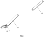
FIG. 3 is a schematic structural diagram of a first angle of a vehicle door opening and closing device provided in embodiments of the present disclosure. - The following is a supplementary explanation for the accompanying drawings:
- 10-active arm; 11-active arm vehicle body end; 12-active arm vehicle door end;
- 20-guide rail seat; 21-guide rail;
- 30-driven mechanism; 31-first driven arm; 32-second driven arm; 321-limiting groove.
- In order to enable those skilled in the art to better understand the solution of the present disclosure, a clear and complete description of the technical solution in the embodiments of the present disclosure will be provided below in conjunction with the accompanying drawings. The described embodiments are only a part of the embodiments of the present disclosure, and not all of the embodiments. Other embodiments achieved by those skilled in the art according to the embodiments in the present disclosure without paying creative work shall all fall within the scope of protection of the present disclosure.
- The term "an embodiment" or "embodiments" herein refers to a feature, a structure, or a characteristic that may be included in at least one embodiment of the present disclosure. In the description of the present disclosure, it should be understood that the terms "up", "down", "top", and "bottom", etc. indicate orientation or positional relationships based on the orientation or positional relationships shown in the accompanying drawings, which is only for the convenience of describing the present disclosure and simplifying the description, instead of indicating or implying that the device or component referred to must have a specific orientation, be constructed and operated in a specific orientation, and therefore cannot be understood as a limitation of the present disclosure. In addition, the terms "first" and "second" are only for descriptive purposes, and cannot be understood as indicating or implying relative importance or implying the quantity of the technical feature indicated. Therefore, features limited by "first" and "second" can explicitly or implicitly include one or more of these features. Moreover, the terms "first", and "second", etc. are used to distinguish similar objects and are not necessarily used to describe a particular order or sequence. It should be understood that the objects defined by "first" and "second" may be interchangeable in appropriate circumstances, such that the embodiments described herein can be implemented in order other than those illustrated or described herein.
- In order to facilitate the explanation of the advantages of the vehicle door opening and closing device in the embodiments of the present disclosure, at the beginning of the description of the technical solution of the embodiments of the present disclosure, the relevant content is first summarized.
- In related arts, in the width direction of the vehicle body, there is partial structural overlap between the front swing door and the rear swing door on the same side of a B-pillar free vehicle model, and therefore the front swing door has a position limiting effect on the rear swing door. The opening of the rear swing door of the B-pillar free vehicle model adopts a four-bar linkage mechanism, which causes the rear swing door to rotate outward when the rear swing door starts swinging. Due to the limit of the front swing door on the rear swing door, it is generally necessary to open the front swing door first before the rear swing door can be opened, and the rear swing door cannot be opened separately, resulting in a poor driving experience for users.
- In view of the shortcomings in the related arts, in the present disclosure, the vehicle door opening and closing device is provided with a guide rail that matches a predefined opening and closing trajectory of the vehicle door on a guide rail seat, and a first sliding part that slides along the guide rail on a driven mechanism, such that the vehicle door can be opened and closed separately along the predefined opening and closing trajectory of the vehicle door under the drive of an active arm, without being limited to another vehicle door, thereby improving the experience of passengers.
- Referring to
FIG.s 1 to 3 . In the embodiments of the present disclosure, the vehicle door opening and closing device is applied to the opening and closing of the rear vehicle door of a B-pillar free vehicle model. The vehicle door opening and closing device includes anactive arm 10, aguide rail seat 20, and a drivenmechanism 30. The active armvehicle body end 11 of theactive arm 10 is rotatably connected to the vehicle body, and the active armvehicle door end 12 of theactive arm 10 is rotatably connected to the vehicle door. Theguide rail seat 20 is fixed on the vehicle door, and theguide rail seat 20 is provided with aguide rail 21 that matches the predefined opening and closing trajectory of the vehicle door. One end of the drivenmechanism 30 is rotatably connected to theguide rail seat 20, and the other end of the drivenmechanism 30 is rotatably connected to the vehicle body. The drivenmechanism 30 is provided with a first sliding part, where the first sliding part is slidably connected to theguide rail 21. - In an embodiment, the vehicle door is provided with a mounting seat for the guide rail seat, and the
guide rail seat 20 is fixedly mounted on the mounting seat for the guide rail seat. For example, the mounting seat for the guide rail seat is provided on a side of the vehicle door facing the interior space of the vehicle. - In an embodiment, the
guide rail seat 20 is provided with aguide rail 21, where theguide rail 21 is used to constrain the moving trajectory of the vehicle door. - In an embodiment, the driven
mechanism 30 is connected to theguide rail seat 20 and the vehicle body. For example, an end of the drivenmechanism 30 close to the vehicle door is rotatably connected to theguide rail seat 20, and an end of the drivenmechanism 30 close to the vehicle body is rotatably connected to the vehicle body. - For example, an end of the driven
mechanism 30 close to the vehicle door is movably riveted to theguide rail seat 20, and an end of the drivenmechanism 30 close to the vehicle body is connected to the vehicle body through a pin (also referred to as a pin roll) for rotation. - In an embodiment, the driven
mechanism 30 is protrudingly provided with a first sliding part, where the first sliding part slides in conjunction with theguide rail 21. - In an embodiment, for a B-pillar free vehicle model, when both the front and rear vehicle doors are closed, an end of the front vehicle door close to the rear vehicle door and an end of the rear vehicle door close to the front vehicle door overlap along the width direction of the vehicle body, and the end of the rear vehicle door close to the front vehicle door is located on the inner side of the end of the front vehicle door close to the rear vehicle door, that is, the end of the front vehicle door close to the rear vehicle door is an interference area of the front vehicle door with respect to the opening and closing of the rear vehicle door.
- In the embodiments of the present disclosure, the vehicle door opening and closing device is provided with a guide rail that matches a predefined opening and closing trajectory of the vehicle door on a guide rail seat, and a first sliding part that slides along the guide rail on a driven mechanism, such that the vehicle door can be opened and closed separately along the predefined opening and closing trajectory of the vehicle door under the drive of an active arm, without being limited to another vehicle door, thereby improving the experience of passengers.
- In the embodiments of the present disclosure, the driven
mechanism 30 includes a first drivenarm 31 and a second drivenarm 32 that are rotatably connected. An end of the first drivenarm 31 away from the second drivenarm 32 is rotatably connected to the vehicle body, and an end of the second drivenarm 32 away from the first drivenarm 31 is rotatably connected to theguide rail seat 20. The first sliding part is provided on the first drivenarm 31. - In an embodiment, the end of the first driven
arm 31 away from the second drivenarm 32 is rotatably connected to the vehicle body through a pin, and the end of the second drivenarm 32 away from the first drivenarm 31 is movably riveted to theguide rail seat 20. - In an embodiment, during the relative movement of the vehicle door to the vehicle body, there is both relative rotation and relative sliding between the first driven
arm 31 and the second drivenarm 32. - In the embodiments of the present disclosure, a second sliding part is provided at the end of the first driven
arm 31 close to the second drivenarm 32, and aposition limiting groove 321 matching the second sliding part is provided at the end of the second drivenarm 32 close to the first drivenarm 31. The second sliding part is rotatably connected to theposition limiting groove 321, and the size of theposition limiting groove 321 in the length direction is greater than the outer diameter of the second sliding part. - In an embodiment, a second sliding part is protruding from the end of the first driven
arm 31 close to the second drivenarm 32. The second sliding part rotates in theposition limiting groove 321 and slides in theposition limiting groove 321 to move the vehicle door along the predefined opening and closing trajectory of the vehicle door. - In an embodiment, the size of the limiting
groove 321 in the length direction is greater than the outer diameter of the second sliding part, such that the second sliding part can slide along the length direction of the limitinggroove 321 in the limitinggroove 321. - In the embodiments of the present disclosure, the first sliding part is provided between the end of the first driven
arm 31 away from the second drivenarm 32 and the second sliding part, to achieve the movement of the vehicle door along the predefined opening and closing trajectory of the vehicle door. - In the embodiments of the present disclosure, the first sliding part includes a first sliding shaft and a first position limiting end that are fixedly connected, the first sliding shaft is fixedly connected to the first driven
arm 31, and the first position limiting end has a larger diameter than the first sliding shaft. - In an embodiment, the first sliding part is the first ball-head pin, where the first sliding shaft is a first smooth shaft sliding along the
guide rail 21, the first position limiting end is a first spherical end, and the diameter of the first spherical end is greater than the outer diameter of the first smooth shaft, so as to prevent the first ball-head pin from slipping out of theguide rail 21. - For example, the
guide rail 21 is a first conical guide rail, and the opening of theguide rail 21 towards the first drivenarm 31 is smaller than the opening of theguide rail 21 towards the vehicle door. - For example, the first ball-head pin and the first conical guide rail are slidably snapped together.
- In the embodiments of the present disclosure, the second sliding part includes a second sliding shaft and a second position limiting end that are fixedly connected. The second sliding shaft is fixedly connected to the first driven
arm 31, and the second position limiting end has a larger diameter than the second sliding shaft. - In an embodiment, the second sliding part is a second ball-head pin roll, where the second sliding shaft is a second smooth shaft that slides along the
position limiting groove 321, and the second position limiting end is a second spherical end, the diameter of the second spherical end is greater than the outer diameter of the second smooth shaft, so as to prevent the second ball-head pin from slipping out of theposition limiting groove 321. - For example, the
position limiting groove 321 is a second conical guide rail, and the opening of theposition limiting groove 321 close to the first drivenarm 31 is smaller than the opening of theposition limiting groove 321 close to theguide rail seat 20. - For example, the second ball-head pin and the second conical guide rail are slidably snapped together.
- In the embodiments of the present disclosure, the vehicle door opening and closing device includes at least two
guide rail seats 20 and at least two drivenmechanisms 30, and the at least two theguide rail seats 20 are provided respectively corresponding to the at least two the drivenmechanisms 30. - In an embodiment, a
guide rail seat 20, a drivenmechanism 30, and anactive arm 10 are provided between a lower end side of the vehicle door and the vehicle body, and aguide rail seat 20 and a drivenmechanism 30 are provided between an upper end side of the vehicle door and the vehicle body, thereby increasing the stability of the vehicle door opening and closing device connecting the vehicle door and the vehicle body. - In another embodiment, a
guide rail seat 20 and a drivenmechanism 30 are provided between the lower end side of the vehicle door and the vehicle body, and aguide rail seat 20, a drivenmechanism 30, and anactive arm 10 are provided between the upper end side of the vehicle door and the vehicle body, thereby increasing the stability of the vehicle door opening and closing device connecting the vehicle door and the vehicle body. - In the embodiments of the present disclosure, the vehicle door opening and closing device further includes a driving mechanism, where the driving mechanism is electrically connected to a vehicle controller, and the driving mechanism is in transmission connection with the
active arm 10. - In an embodiment, the control system of the vehicle controls the driving mechanism to operate in response to a vehicle door opening or closing signal, and the driving mechanism drives the
active arm 10 to rotate through the transmission mechanism. - In the embodiments of the present disclosure, the
guide rail 21 is S-shaped, and theposition limiting groove 321 is strip-shaped. - In an embodiment, the
position limiting groove 321 is a waist shaped hole groove to allow the vehicle door to move along the predefined opening and closing trajectory of the vehicle door under the drive of theactive arm 10. - For example, when the front vehicle door is closed and the rear vehicle door needs to be opened, the control system of the vehicle controls the driving mechanism to operate in response to the vehicle door opening signal. The driving mechanism drives the
active arm 10 to rotate through the transmission mechanism. The end of the rear vehicle door that is far away from the front vehicle door moves around the active armvehicle body end 11 under the driving of theactive arm 10, and the first sliding part on the first drivenarm 31 slides in theguide rail 21, the second sliding part on the first drivenarm 31 rotates in theposition limiting groove 321 and slides along the position limiting groove, and the second drivenarm 32 rotates around theguide rail seat 20. Through the coordinated movement of the first slidingpart 21, the second sliding part, the second drivenarm 32, and theguide rail seat 20, the constraint on the movement of the rear vehicle door by theguide rail 21, the first drivenarm 31, and the second drivenarm 32 is achieved, such that when the rear vehicle door starts to open, the end of the rear vehicle door close to the front vehicle door first performs translational motion to a place where the end of the rear vehicle door close to the front vehicle door leaves the interference area of the front vehicle door for the opening and closing of the rear vehicle door, and then continues to swing, so as to fully open the rear vehicle door according to the predefined opening and closing trajectory of the vehicle door. - The movement trajectory of the rear vehicle door when the rear vehicle door is closed is consistent with that when the rear vehicle door is opened. For example, when the rear vehicle door needs to be closed, the control system of the vehicle controls the driving mechanism to operate in response to the vehicle door closing signal. The driving mechanism drives the
active arm 10 to rotate in an opposite direction through the transmission mechanism, and the rear vehicle door swings under the driving of theactive arm 10. The first sliding part on the first drivenarm 31 slides in theguide rail 21, the second sliding part on the first drivenarm 31 rotates in theposition limiting groove 321 and slides along the position limiting groove, and the second drivenarm 32 rotates with theguide rail seat 20. Through the coordinated movement of the first slidingpart 21, the second sliding part, the second drivenarm 32, and theguide rail seat 20, the constraint on the movement of the rear vehicle door by theguide rail 21, the first drivenarm 31, and the second drivenarm 32 is achieved, such that before the rear vehicle door closes, the end of the rear vehicle door close to the front vehicle door performs translational motion to avoid the interference area of the front vehicle door on the opening and closing of the rear vehicle door, such that the rear vehicle door can be completely closed according to the predefined opening and closing trajectory of the vehicle door. - In addition, the embodiments of the present disclosure further provide a vehicle including the vehicle door opening and closing device as described above.
- In the present disclosure, the vehicle door opening and closing device is provided with a guide rail that matches a predefined opening and closing trajectory of the vehicle door on a guide rail seat, and a first sliding part that slides along the guide rail on a driven mechanism, such that the vehicle door can be opened and closed separately along the predefined opening and closing trajectory of the vehicle door under the drive of an active arm, without being limited to another vehicle door, thereby improving the experience of passengers.
- The foregoing disclosure is merely illustrative of preferred examples of the present disclosure but not intended to limit the present disclosure, and any modifications, equivalent substitutions, adaptations thereof made within the spirit and principles of the disclosure shall be encompassed in the scope of protection of the present disclosure.
Claims (10)
- A vehicle door opening and closing device, comprising an active arm (10), a guide rail seat (20), and a driven mechanism (30); whereinan active arm vehicle body end (11) of the active arm (10) is rotatably connected to a vehicle body, and an active arm vehicle door end (12) of the active arm (10) is rotatably connected to a vehicle door;the guide rail seat (20) is fixedly mounted on the vehicle door, and the guide rail seat (20) is provided with a guide rail (21) that matches a predefined opening and closing trajectory of the vehicle door;one end of the driven mechanism (30) is rotatably connected to the guide rail seat (20), and the other end of the driven mechanism (30) is rotatably connected to the vehicle body; andthe driven mechanism (30) is provided with a first sliding part, wherein the first sliding part is slidably connected to the guide rail (21).
- The vehicle door opening and closing device according to claim 1, wherein the driven mechanism (30) comprises a first driven arm (31) and a second driven arm (32) that are rotatably connected; whereinan end of the first driven arm (31) away from the second driven arm (32) is rotatably connected to the vehicle body, and an end of the second driven arm (32) away from the first driven arm (31) is rotatably connected to the guide rail seat (20); andthe first sliding part is provided on the first driven arm (31).
- The vehicle door opening and closing device according to claim 2, wherein a second sliding part is provided at an end of the first driven arm (31) close to the second driven arm (32), and a position limiting groove (321) that matches with the second sliding part is provided at an end of the second driven arm (32) close to the first driven arm (31); wherein
the second sliding part is rotatably connected to the position limiting groove (321), and a size of the position limiting groove (321) in a length direction is greater than an outer diameter of the second sliding part. - The vehicle door opening and closing device according to claim 3, wherein the first sliding part is provided between the end of the first driven arm (31) away from the second driven arm (32) and the second sliding part.
- The vehicle door opening and closing device according to claim 1, wherein the first sliding part comprises a first sliding shaft and a first position limiting end that are fixedly connected, the first sliding shaft is fixedly connected to the first driven arm (31), and the first position limiting end has a larger diameter than the first sliding shaft.
- The vehicle door opening and closing device according to claim 3, wherein the second sliding part comprises a second sliding shaft and a second position limiting end that are fixedly connected, the second sliding shaft is fixedly connected to the first driven arm (31), and the second position limiting end has a larger diameter than the second sliding shaft.
- The vehicle door opening and closing device according to claim 1, comprising at least two of the guide rail seats (20) and at least two of the driven mechanisms (30), and the at least two of the guide rail seats (20) are provided respectively corresponding to the at least two of the driven mechanisms (30).
- The vehicle door opening and closing device according to claim 1, further comprising: a driving mechanism, wherein the driving mechanism is electrically connected to a vehicle controller; and
the driving mechanism is in transmission connection with the active arm (10). - The vehicle door opening and closing device according to claim 3, wherein the guide rail (21) is S-shaped, and the position limiting groove (321) is strip-shaped.
- A vehicle, comprising the vehicle door opening and closing device according to any one of claims 1-9.
Applications Claiming Priority (2)
| Application Number | Priority Date | Filing Date | Title |
|---|---|---|---|
| CN202210639343.7A CN114961489B (en) | 2022-06-07 | 2022-06-07 | Door opening and closing device and car |
| PCT/CN2023/097932 WO2023236854A1 (en) | 2022-06-07 | 2023-06-02 | Vehicle door opening and closing device and vehicle |
Publications (2)
| Publication Number | Publication Date |
|---|---|
| EP4520902A1 true EP4520902A1 (en) | 2025-03-12 |
| EP4520902A4 EP4520902A4 (en) | 2025-08-06 |
Family
ID=82972166
Family Applications (1)
| Application Number | Title | Priority Date | Filing Date |
|---|---|---|---|
| EP23819019.3A Pending EP4520902A4 (en) | 2022-06-07 | 2023-06-02 | VEHICLE DOOR OPENING AND CLOSING DEVICE AND VEHICLE |
Country Status (5)
| Country | Link |
|---|---|
| US (1) | US20250092730A1 (en) |
| EP (1) | EP4520902A4 (en) |
| CN (1) | CN114961489B (en) |
| AU (1) | AU2023283511B2 (en) |
| WO (1) | WO2023236854A1 (en) |
Families Citing this family (6)
| Publication number | Priority date | Publication date | Assignee | Title |
|---|---|---|---|---|
| WO2023079984A1 (en) * | 2021-11-02 | 2023-05-11 | 株式会社アイシン | Vehicle door device |
| CN114961489B (en) * | 2022-06-07 | 2024-05-17 | 浙江极氪智能科技有限公司 | Door opening and closing device and car |
| CN115450521B (en) * | 2022-09-27 | 2025-06-06 | 广东东箭汽车智能系统有限公司 | Cam sliding door device and vehicle thereof |
| CN115450522B (en) * | 2022-09-28 | 2025-04-15 | 广东东箭汽车智能系统有限公司 | Double-cam trackless side sliding door and vehicle thereof |
| CN118855336B (en) * | 2024-07-03 | 2025-11-07 | 宁波华楷电子科技有限公司 | Vehicle side swing door and opening method thereof |
| CN121756861A (en) * | 2024-09-30 | 2026-03-31 | 比亚迪股份有限公司 | Vehicle side sliding door assembly and driving mechanism thereof, and vehicle |
Family Cites Families (20)
| Publication number | Priority date | Publication date | Assignee | Title |
|---|---|---|---|---|
| GB8628384D0 (en) * | 1986-11-27 | 1986-12-31 | Westinghouse Brake & Signal | Plug door arrangement |
| FR2727460A1 (en) * | 1994-11-24 | 1996-05-31 | Peugeot | Hinge mechanism for car doors with two track rods forming quadrilateral |
| DE19634369C1 (en) * | 1996-08-26 | 1997-09-18 | Daimler Benz Ag | Guide for parallel-sliding door on vehicle bodywork with support element |
| DE19704811C1 (en) * | 1997-02-08 | 1998-10-01 | Webasto Tuersysteme Gmbh | Door hinge mechanism for e.g. motor vehicles |
| DE102004016091B4 (en) * | 2003-07-24 | 2016-02-18 | Volkswagen Ag | Device for guiding a sliding door |
| JP2006257678A (en) * | 2005-03-15 | 2006-09-28 | Toyota Motor Corp | Vehicle door structure |
| JP4658694B2 (en) * | 2005-05-31 | 2011-03-23 | 株式会社ミツバ | Vehicle door opening and closing structure |
| US7488029B2 (en) * | 2005-12-16 | 2009-02-10 | Ford Global Technologies, Llc | Independently opening doors for an automotive door opening |
| DE102009057309A1 (en) * | 2009-12-07 | 2011-06-09 | Dura Automotive Body & Glass Systems Gmbh | Vehicle with a sliding door |
| KR101338781B1 (en) * | 2011-12-14 | 2014-01-03 | 현대자동차주식회사 | Sliding door without rail |
| JP6583685B2 (en) * | 2016-01-21 | 2019-10-02 | 三井金属アクト株式会社 | Door opener |
| DE102017008872A1 (en) * | 2017-09-21 | 2019-03-21 | Audi Ag | Motor vehicle with a door device and door device for a motor vehicle |
| US10876341B2 (en) * | 2018-07-24 | 2020-12-29 | Brose Fahrzeugteile Gmbh & Co. Kommanditgesellschaft, Bamberg | Door drive system |
| JP7600803B2 (en) * | 2021-03-19 | 2024-12-17 | 株式会社アイシン | Vehicle door device |
| WO2023079984A1 (en) * | 2021-11-02 | 2023-05-11 | 株式会社アイシン | Vehicle door device |
| JP7767901B2 (en) * | 2021-12-21 | 2025-11-12 | 株式会社アイシン | Vehicle door device |
| US20230382203A1 (en) * | 2022-05-24 | 2023-11-30 | Aisin Corporation | Vehicle door device |
| CN114961489B (en) * | 2022-06-07 | 2024-05-17 | 浙江极氪智能科技有限公司 | Door opening and closing device and car |
| CN217778315U (en) * | 2022-07-26 | 2022-11-11 | 比亚迪股份有限公司 | Vehicle with a steering wheel |
| JP2025152638A (en) * | 2024-03-28 | 2025-10-10 | 株式会社アイシン | Vehicle door device |
-
2022
- 2022-06-07 CN CN202210639343.7A patent/CN114961489B/en active Active
-
2023
- 2023-06-02 AU AU2023283511A patent/AU2023283511B2/en active Active
- 2023-06-02 WO PCT/CN2023/097932 patent/WO2023236854A1/en not_active Ceased
- 2023-06-02 EP EP23819019.3A patent/EP4520902A4/en active Pending
-
2024
- 2024-12-03 US US18/966,930 patent/US20250092730A1/en active Pending
Also Published As
| Publication number | Publication date |
|---|---|
| AU2023283511B2 (en) | 2026-03-05 |
| CN114961489B (en) | 2024-05-17 |
| AU2023283511A1 (en) | 2024-12-19 |
| WO2023236854A1 (en) | 2023-12-14 |
| US20250092730A1 (en) | 2025-03-20 |
| EP4520902A4 (en) | 2025-08-06 |
| CN114961489A (en) | 2022-08-30 |
Similar Documents
| Publication | Publication Date | Title |
|---|---|---|
| US20250092730A1 (en) | Vehicle door opening and closing device and vehicle | |
| CN113668967B (en) | Door hinge structure and vehicle | |
| CN113266223B (en) | A scissor door hinge and vehicle | |
| CN118881268B (en) | Dual-mode vehicle door electric system and vehicle with same | |
| US5850711A (en) | Vehicle window opening/closing device | |
| CN118953433A (en) | Movable pedal linkage mechanism for escape door and working method thereof | |
| CN220909446U (en) | Hinge assembly and vehicle of door | |
| CN108301726A (en) | A kind of four link type automatically-controlled door open and close mechanism, automatically-controlled door and automobile | |
| CN210289456U (en) | Hidden automobile outward opening door handle | |
| CN116122689A (en) | Double-door linkage mechanism of mobile vending service robot | |
| CN220247869U (en) | Double-rotation-shaft hinge assembly and automobile body assembly adopting same | |
| CN217652552U (en) | Hinge for automobile scissor door | |
| CN215332234U (en) | Scissors door structure that can initiatively open and shut | |
| CN202990569U (en) | Handle outside car door and car | |
| CN217106623U (en) | Opening and closing mechanism for vehicle tail gate | |
| CN216116698U (en) | Mechanical arm, testing device and start-stop testing system | |
| CN115230444A (en) | Door module and vehicle | |
| CN212376474U (en) | Door handle overload protection structure | |
| CN217778315U (en) | Vehicle with a steering wheel | |
| CN222823080U (en) | A track guide device for vehicle side swing door | |
| CN219654527U (en) | Sliding plug door | |
| CN223880963U (en) | Hing structure for vehicle trunk lid | |
| CN218085037U (en) | Bus door and bus with same | |
| CN224149386U (en) | A novel pneumatic chamber drive mechanism | |
| CN114056441B (en) | A railway carriage subassembly and vehicle for vehicle |
Legal Events
| Date | Code | Title | Description |
|---|---|---|---|
| STAA | Information on the status of an ep patent application or granted ep patent |
Free format text: STATUS: THE INTERNATIONAL PUBLICATION HAS BEEN MADE |
|
| PUAI | Public reference made under article 153(3) epc to a published international application that has entered the european phase |
Free format text: ORIGINAL CODE: 0009012 |
|
| STAA | Information on the status of an ep patent application or granted ep patent |
Free format text: STATUS: REQUEST FOR EXAMINATION WAS MADE |
|
| 17P | Request for examination filed |
Effective date: 20241203 |
|
| AK | Designated contracting states |
Kind code of ref document: A1 Designated state(s): AL AT BE BG CH CY CZ DE DK EE ES FI FR GB GR HR HU IE IS IT LI LT LU LV MC ME MK MT NL NO PL PT RO RS SE SI SK SM TR |
|
| A4 | Supplementary search report drawn up and despatched |
Effective date: 20250708 |
|
| RIC1 | Information provided on ipc code assigned before grant |
Ipc: E05D 15/58 20060101AFI20250702BHEP Ipc: E05D 15/28 20060101ALI20250702BHEP Ipc: E05D 15/30 20060101ALI20250702BHEP Ipc: E05D 15/10 20060101ALI20250702BHEP Ipc: E05F 15/63 20150101ALI20250702BHEP |
|
| DAV | Request for validation of the european patent (deleted) | ||
| DAX | Request for extension of the european patent (deleted) | ||
| STAA | Information on the status of an ep patent application or granted ep patent |
Free format text: STATUS: EXAMINATION IS IN PROGRESS |
|
| 17Q | First examination report despatched |
Effective date: 20260129 |