EP4520901A1 - Magnetischer riegelbetätigungsmechanismus, schlosssatz und tür - Google Patents
Magnetischer riegelbetätigungsmechanismus, schlosssatz und tür Download PDFInfo
- Publication number
- EP4520901A1 EP4520901A1 EP23306488.0A EP23306488A EP4520901A1 EP 4520901 A1 EP4520901 A1 EP 4520901A1 EP 23306488 A EP23306488 A EP 23306488A EP 4520901 A1 EP4520901 A1 EP 4520901A1
- Authority
- EP
- European Patent Office
- Prior art keywords
- operation mechanism
- slider
- lockset
- lock
- latch body
- Prior art date
- Legal status (The legal status is an assumption and is not a legal conclusion. Google has not performed a legal analysis and makes no representation as to the accuracy of the status listed.)
- Pending
Links
Images


Classifications
-
- E—FIXED CONSTRUCTIONS
- E05—LOCKS; KEYS; WINDOW OR DOOR FITTINGS; SAFES
- E05C—BOLTS OR FASTENING DEVICES FOR WINGS, SPECIALLY FOR DOORS OR WINDOWS
- E05C19/00—Other devices specially designed for securing wings, e.g. with suction cups
- E05C19/16—Devices holding the wing by magnetic or electromagnetic attraction
- E05C19/163—Devices holding the wing by magnetic or electromagnetic attraction a movable bolt being held in the striker by a permanent magnet
-
- E—FIXED CONSTRUCTIONS
- E05—LOCKS; KEYS; WINDOW OR DOOR FITTINGS; SAFES
- E05B—LOCKS; ACCESSORIES THEREFOR; HANDCUFFS
- E05B63/00—Locks or fastenings with special structural characteristics
- E05B63/0056—Locks with adjustable or exchangeable lock parts
-
- E—FIXED CONSTRUCTIONS
- E05—LOCKS; KEYS; WINDOW OR DOOR FITTINGS; SAFES
- E05B—LOCKS; ACCESSORIES THEREFOR; HANDCUFFS
- E05B47/00—Operating or controlling locks or other fastening devices by electric or magnetic means
- E05B47/0038—Operating or controlling locks or other fastening devices by electric or magnetic means using permanent magnets
-
- E—FIXED CONSTRUCTIONS
- E05—LOCKS; KEYS; WINDOW OR DOOR FITTINGS; SAFES
- E05B—LOCKS; ACCESSORIES THEREFOR; HANDCUFFS
- E05B9/00—Lock casings or latch-mechanism casings ; Fastening locks or fasteners or parts thereof to the wing
- E05B9/002—Faceplates or front plates
Definitions
- the disclosure relates to a magnetic latch operation mechanism, as well as to a lockset and door incorporating such a magnetic latch operation mechanism.
- latch operation mechanisms In order to improve the reliability and reduce the cost of locksets, it has been generally sought to simplify latch operation mechanisms and reduce their number of parts while maintaining or even increasing their functionalities.
- magnetically actuated latch operation mechanisms have been proposed, for instance in Italian patent application publication ITMI20011504A1 , which also has the advantage of being more silent than a conventional latch operation mechanism, since the latch remains in a retracted position until it is aligned with the striker cavity, and thus does not hit the door jamb or a striker plate as the door leaf closes.
- the operative linkage between the operating spindle and the latch for retracting the latch, once extended, back into the retracted position remains complex.
- the relative vertical distance between the latch and the operating spindle is fixed, and cannot be easily adapted for different requirements in this respect.
- a first object of the disclosure is that of providing a magnetic latch operation mechanism with a simpler, cheaper and more reliable structure, involving a minimum number of moving parts with simple movements.
- a magnetic latch operation mechanism comprises a latch body, configured to be guided in a first direction between a retracted position and an extended position and to be magnetically attracted towards the extended position when aligned with a magnetic striker, wherein the latch body has an opening partially delimited by an inclined actuation surface, which is inclined with respect to the first direction, and a slider, configured to be guided in a second direction substantially perpendicular to the first direction and comprising a first pin configured to be received, substantially perpendicularly to said first and second directions, in said opening, and to operatively engage the inclined actuation surface to move the latch body towards the retracted position along a first axis in the first direction.
- the first direction may be a substantially horizontal direction and the second direction a substantially vertical direction, wherein “horizontal” and “vertical” should be understood as referring to directions when the magnetic latch operation mechanism is mounted within a lockset in a functional door assembly.
- the slider may comprise a second pin, offset from the first pin in the second direction, and configured to be received in said opening, substantially perpendicularly to said first and second directions, alternatively from the first pin.
- This second pin may then be received in the opening, instead of the first pin and operatively engage the inclined actuation surface, to move the latch body along the second axis in the first direction towards a retracted position.
- the slider may have at least one actuation surface configured to be engaged by a rotary pawl to push the slider in the second direction to move the latch body towards the retracted position.
- the latch operation mechanism may comprise the rotary pawl and a spindle operatively coupled to the rotary pawl and configured to be operatively coupled to at least one handle or knob. The retraction of the latch body may thus be actuated by the rotary pawl and spindle through the slider.
- the slider may have not just one, but at least two actuation surfaces, offset from each other in the second direction, and each configured to be selectively engaged by the rotary pawl to push the slider to move the latch body towards the retracted position, so as to provide at least two alternative positions for a rotation axis of the rotary pawl with respect to the slider, and thus offer even greater versatility for the installation of the latch mechanism.
- the slider may have a holding surface, configured to be engaged by a lock cam to lock the slider in a locking position in which the first pin is held in a pocket extending from an end of the inclined actuation surface of the latch body to retain the latch body in the extended position.
- a perimeter of said opening in the latch body may include an inwardly protruding detent portion between the inclined actuation surface and a bottom of the pocket, so as to secure the first pin in the pocket and provide a haptic feedback when unlocking the latch body.
- a second aspect of the present disclosure relates to a lockset comprising the latch operation mechanism according to the first aspect and a housing receiving the latch operation mechanism.
- the housing may comprise a front plate and a front plate cover magnetically attached to the front plate.
- the front plate may be ferromagnetic and the front plate cover comprise one or more permanent magnets.
- the permanent magnet may be incorporated in a back surface of the front plate cover. It may for instance be cut from ferrite magnet sheeting, incorporating ferrite powder into an organic polymer matrix.
- Other types of magnets for instance alnico magnets or rare earth magnets, in particular neodymium magnets, may however be considered instead.
- the lockset may further comprising a lock adaptor received into the housing and configured to receive a lock, which may in particular be a key lock, a cylinder lock, or a thumb turn lock.
- a lock which may in particular be a key lock, a cylinder lock, or a thumb turn lock.
- the lockset may also comprise the magnetic striker.
- a third aspect of the present disclosure relates to a door assembly comprising a frame and a leaf connected by one or more hinges, and the lockset according to the second aspect.
- substantially perpendicular In the present context, “substantially perpendicular”, “substantially parallel”, “substantially horizontal” or “substantially vertical” should be understood as meaning perpendicular, parallel, horizontal or vertical within a reasonable margin, such as, for example, ⁇ 10° or ⁇ 5°.
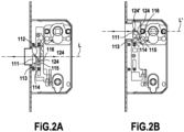
- a lockset 10 may comprise a magnetic latch operation mechanism 100, a housing 200, a lock module 300, and a counterplate 400.
- the magnetic latch operation mechanism 100 may comprise a latch body 110, a slider 120, a rotary pawl 130, and a spindle 140.
- the latch body 110 may be configured to be guided along a first translation axis L in a first direction X, which may in particular be a substantially horizontal direction, between an extended position, in which the latch body 110 may partially protrude out of the housing 200, and a retracted position, in which the latch body 110 may be substantially contained within the housing 200.
- the latch body 110 may alternatively be guided between corresponding extended and retracted positions along a second translation axis L', substantially parallel to the first translation axis L, but relatively offset in a second direction Z, substantially perpendicular to the first direction, as respectively shown on Figs. 2A and 2B .
- This second direction Z may in particular be a substantially vertical direction.
- the rotary pawl 130 may be operatively connected to the spindle 140, which may in turn be configured to be operatively coupled to a handle 700 or knob, for instance through a non-rotationally symmetric bore, such as the illustrated square cross-section bore 141.
- the spindle 140 and rotary pawl 130 may be configured to turn around first or second rotation axes R, R' oriented in a third direction Y, substantially perpendicular to both the first and second directions X,Z, between a rest position and an operation position.
- the spindle 140 and rotary pawl 130 may be spring-loaded towards the rest position, so as to automatically return to this rest position after their operation.
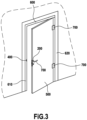
- the housing 200 may be configured to receive the magnetic latch operation mechanism 100 and be installed within a hinged door leaf 500, as shown in Fig. 3 .
- the counterplate 400 may be installed in a door frame 600, in particular within a door jamb 610 opposite to the door jamb 620 on which the one or more hinges 700 linking the door frame 600 to the door leaf 400 may be installed.
- the counterplate 400 may comprise a magnetic striker 410.
- the housing 200 may comprise a casing 210, a front plate 220, a front plate cover 230, and a side cover 240. Transverse columns 260 may extend, within the housing 200, between the side cover 240 and an opposite face of the casing 210, connecting them.
- the front plate 220 may have two latch openings 221, 222, respectively located so as to allow passage of the latch body 110 from the retracted to the extended position on the first or second translation axes L, L'.
- the front plate 220 may also have fastening orifices 223 for fastening elements such as, in particular, countersunk screws.
- the front plate cover 230 may be magnetically attached to the front plate 220.
- the front plate 220 may be ferromagnetic and the front plate cover 230 comprise one or more permanent magnets, although other arrangements, for instance with a ferromagnetic front plate cover 230 and one or more permanent magnets integrated in the front plate 220, may alternatively be considered.
- the front plate cover 230 may comprise a single latch opening 231, aligned with one of the latch openings 221, 222 in the front plate 220, to allow passage of the latch body 110 from the retracted to the extended position on the corresponding translation axis L, L', while substantially covering the remaining surface of the front plate 220, including the other latch opening 222, 221 and the fastening orifices 221.
- the front plate cover 230 may be easily replaced with an alternative front plate cover having its single latch opening aligned with said other latch opening 222, 221 in the front plate 220, if the latch body 110 is to be installed on the corresponding other translation axis L', L.
- the front plate cover 230 may comprise a decorative outer surface 231, for instance to emulate the appearance of the surrounding area on the door leaf edge.
- Both the casing 210 and side cover 240 may have respective first openings 211,241, opposite to each other, for receiving the spindle 140, as well as respective second openings 212,242, also opposite to each other, for receiving the lock module 300.
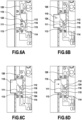
- the openings 211, 241 may be shaped so as to alternatively accommodate the spindle 140 in two alternative positions, respectively illustrated in Figs. 4A and 4B , and offset from each other in the second direction Z, so that the spindle 140 is rotationally supported around either the first rotation axis R or the second rotation axis R'.
- the housing 200 may additionally comprise a reversible insert 250, with separate first and second parts 251,252, to support the spindle 140 within the housing 200 and close up the openings 211, 241.
- the openings 211, 241 may be substantially symmetrical with respect to a symmetry plane S perpendicular to the second direction Z, so that the reversible insert 250 may be vertically flipped with respect to this symmetry plane S to alternatively support the spindle 140 in the position of Fig. 4A or in the position of Fig. 4B .
- the lock module 300 may comprise a lock adaptor 310 and a lock 320.
- the lock adaptor 310 may comprise two parts 311, 312, configured to be fastened to each other with the lock 320 held between them.
- the lock 320 is a simple, keyless thumb turn lock, wherein a lock cam 321 is directly operated through a lock spindle 322 in rotation around a lock cam rotation axis C, which may in particular be oriented in the third direction Y.
- the lock adaptor 310 may shaped complementarily to the lock 320.
- the housing 200 may be configured to receive multiple alternative lock modules including, alternatively to the thumb turn lock 320, a key lock, including a cylinder lock, with an appropriately shaped lock adaptor.
- the lockset 10 may thus be easily adapted to various types of locks by exchanging the lock adaptor 310.
- the slider 120 may in particular comprise one or more oblong holes 121, elongated in the second direction Z, wherein one or more of the transverse columns 260 may be press-fit, in order to guide the slider 120 in the second direction Z.
- the slider 120 may further comprise two actuation surfaces 122,122' configured to be engaged by the rotary pawl 130 when rotating around, respectively, the first rotation axis R or the second rotation axis R', from the rest position to the operation position, to push the slider 120 in the second direction Z.
- the slider 120 may also comprise a holding surface 123 configured to be engaged by the lock cam 321 when the latter is rotated towards a locking position.
- the slider 120 may further comprise two transverse pins 124,124', protruding in the third direction Y and respectively configured to engage the latch body 110 when the latter is located on the first or second translation axes L, L'.
- the latch body 110 may comprise an opening 111 configured to receive either transverse pin 123, 123' in the third direction Y.
- This opening 111 may be delimited by a perimeter comprising an inclined actuation surface 112, which may be inclined with respect to the first and second directions X, Z, a lower edge 113 with a pocket 114 extending from a lower end 116 of the inclined actuation surface 112, and an inwardly protruding detent portion 115 between said lower end 116 of the inclined actuation surface 112 and a bottom of the pocket 114.
- the magnetic striker 410 may be formed by a cavity in the counterplate 400 configured to receive a protruding end of the latch body 110 in the extended position and a permanent magnet at the bottom of this cavity.
- the latch body 110 may be configured to be attracted towards the extended position when aligned with the magnetic striker 410.
- the latch body 110 may be ferromagnetic and/or comprise one or more permanent magnets oriented so as to be attracted towards the permanent magnet of the magnetic striker 410.
- the latch body 110 may be attracted towards the extended position, with its protruding end extending into the cavity of the magnetic striker 141 to hold the door closed.
- the transverse pin 124, 124' may rest between the lower end 116 of the inclined actuation surface 112 and the detent portion 115, as shown in Fig. 6B .
- the transverse pin 124, 124' When the lock cam 321 is turned back into its unlocking position the transverse pin 124, 124' may be brought back out of the pocket 114, over the detent portion 115 and into engagement with the inclined actuation surface 112, as shown in Fig. 6D , to move the latch body 110 back towards its retracted position, by rotation of the spindle 130 and the rotary pawl 140 from their rest position to their operation position and engagement of the rotary pawl 140 with one of the actuation surfaces 122,122' of the slider 120. As the transverse pin 124, 124' moves over the detent portion 115, it may also provide a haptic feedback to the operator of the spindle 130.
- the door may be opened. With the latch body 110 again out of alignment from the magnetic striker 141, the latch body 110 may remain in its retracted position even when the spindle 130 and rotary pawl 140 rotate back to their rest position.
Landscapes
- Engineering & Computer Science (AREA)
- Structural Engineering (AREA)
- Physics & Mathematics (AREA)
- Electromagnetism (AREA)
- Mechanical Engineering (AREA)
- Lock And Its Accessories (AREA)
Priority Applications (2)
| Application Number | Priority Date | Filing Date | Title |
|---|---|---|---|
| EP23306488.0A EP4520901A1 (de) | 2023-09-07 | 2023-09-07 | Magnetischer riegelbetätigungsmechanismus, schlosssatz und tür |
| PCT/EP2024/074940 WO2025051922A1 (en) | 2023-09-07 | 2024-09-06 | Magnetic latch operation mechanism, lockset and door |
Applications Claiming Priority (1)
| Application Number | Priority Date | Filing Date | Title |
|---|---|---|---|
| EP23306488.0A EP4520901A1 (de) | 2023-09-07 | 2023-09-07 | Magnetischer riegelbetätigungsmechanismus, schlosssatz und tür |
Publications (1)
| Publication Number | Publication Date |
|---|---|
| EP4520901A1 true EP4520901A1 (de) | 2025-03-12 |
Family
ID=88315719
Family Applications (1)
| Application Number | Title | Priority Date | Filing Date |
|---|---|---|---|
| EP23306488.0A Pending EP4520901A1 (de) | 2023-09-07 | 2023-09-07 | Magnetischer riegelbetätigungsmechanismus, schlosssatz und tür |
Country Status (2)
| Country | Link |
|---|---|
| EP (1) | EP4520901A1 (de) |
| WO (1) | WO2025051922A1 (de) |
Citations (6)
| Publication number | Priority date | Publication date | Assignee | Title |
|---|---|---|---|---|
| ITMI20011504A1 (it) | 2001-07-13 | 2003-01-13 | Bonaiti Serrature Spa | Serratura ad azionamento magnetico per porta da interni |
| DE202006011379U1 (de) * | 2006-07-25 | 2006-10-26 | Aug. Winkhaus Gmbh & Co. Kg | Treibstangenschloss zur Verriegelung eines Flügels in einem Rahmen |
| EP1288404B1 (de) * | 2001-08-22 | 2007-02-28 | Roto Frank Eisenwarenfabrik Aktiengesellschaft | Mehrriegelschloss |
| WO2017149023A1 (en) * | 2016-03-02 | 2017-09-08 | Bonaiti Serrature S.P.A. | Lock for a rebated door |
| WO2019171290A1 (en) * | 2018-03-07 | 2019-09-12 | Bonaiti Serrature S.P.A. | Antipanic lock |
| WO2020157624A1 (en) * | 2019-02-01 | 2020-08-06 | Alban Giacomo S.P.A. | Closing device for windows and doors |
-
2023
- 2023-09-07 EP EP23306488.0A patent/EP4520901A1/de active Pending
-
2024
- 2024-09-06 WO PCT/EP2024/074940 patent/WO2025051922A1/en active Pending
Patent Citations (6)
| Publication number | Priority date | Publication date | Assignee | Title |
|---|---|---|---|---|
| ITMI20011504A1 (it) | 2001-07-13 | 2003-01-13 | Bonaiti Serrature Spa | Serratura ad azionamento magnetico per porta da interni |
| EP1288404B1 (de) * | 2001-08-22 | 2007-02-28 | Roto Frank Eisenwarenfabrik Aktiengesellschaft | Mehrriegelschloss |
| DE202006011379U1 (de) * | 2006-07-25 | 2006-10-26 | Aug. Winkhaus Gmbh & Co. Kg | Treibstangenschloss zur Verriegelung eines Flügels in einem Rahmen |
| WO2017149023A1 (en) * | 2016-03-02 | 2017-09-08 | Bonaiti Serrature S.P.A. | Lock for a rebated door |
| WO2019171290A1 (en) * | 2018-03-07 | 2019-09-12 | Bonaiti Serrature S.P.A. | Antipanic lock |
| WO2020157624A1 (en) * | 2019-02-01 | 2020-08-06 | Alban Giacomo S.P.A. | Closing device for windows and doors |
Also Published As
| Publication number | Publication date |
|---|---|
| WO2025051922A1 (en) | 2025-03-13 |
Similar Documents
| Publication | Publication Date | Title |
|---|---|---|
| US7634928B2 (en) | Door locking system | |
| US8234892B2 (en) | Mortise lock | |
| US7025394B1 (en) | Lock system for integrating into an entry door having a vertical expanse and providing simultaneous multi-point locking along the vertical expanse of the entry door | |
| US20010009105A1 (en) | Gate latch | |
| US11346130B1 (en) | Double lock dual action gravity latch | |
| AU705146B2 (en) | Bolt unit and frame arrangement | |
| CN111255293B (zh) | 锁组件 | |
| US12258782B2 (en) | Magnetic lockset | |
| US20080211239A1 (en) | Security improvement to solenoid-releasable mortise lockset having thumb-lever actuators | |
| US10519692B1 (en) | Door latch | |
| GB2316440A (en) | Key override monitoring facility for a lock assembly | |
| EP1335085A1 (de) | Verschluss für Schiebetür oder -tor | |
| GB2364545A (en) | Lock operable by separate mechanism from either side of casing | |
| CN1145734C (zh) | 锁 | |
| AU2008344984B2 (en) | Mortice lock with adjustable handing | |
| US20030033839A1 (en) | Mortise latch apparatus | |
| US3884514A (en) | Door latch mechanism | |
| WO2012100107A2 (en) | Mortise lock with deadbolt and magnetic latch | |
| EP4520901A1 (de) | Magnetischer riegelbetätigungsmechanismus, schlosssatz und tür | |
| US4682482A (en) | Deadbolt lock | |
| US11781341B1 (en) | Double latch dual action gravity latch | |
| AU2020268687B2 (en) | Lock assembly | |
| CN105658888B (zh) | 能在滞留模式和防锁定模式下操作的榫眼锁组件 | |
| US20150337574A1 (en) | Deadlock for a door leaf of a door as well as mounting method | |
| CN113463976A (zh) | 内门用紧凑型锁及锁组件 |
Legal Events
| Date | Code | Title | Description |
|---|---|---|---|
| PUAI | Public reference made under article 153(3) epc to a published international application that has entered the european phase |
Free format text: ORIGINAL CODE: 0009012 |
|
| STAA | Information on the status of an ep patent application or granted ep patent |
Free format text: STATUS: THE APPLICATION HAS BEEN PUBLISHED |
|
| AK | Designated contracting states |
Kind code of ref document: A1 Designated state(s): AL AT BE BG CH CY CZ DE DK EE ES FI FR GB GR HR HU IE IS IT LI LT LU LV MC ME MK MT NL NO PL PT RO RS SE SI SK SM TR |
|
| STAA | Information on the status of an ep patent application or granted ep patent |
Free format text: STATUS: REQUEST FOR EXAMINATION WAS MADE |
|
| 17P | Request for examination filed |
Effective date: 20250910 |