EP4520888A1 - Noise reducer - Google Patents
Noise reducer Download PDFInfo
- Publication number
- EP4520888A1 EP4520888A1 EP23195830.7A EP23195830A EP4520888A1 EP 4520888 A1 EP4520888 A1 EP 4520888A1 EP 23195830 A EP23195830 A EP 23195830A EP 4520888 A1 EP4520888 A1 EP 4520888A1
- Authority
- EP
- European Patent Office
- Prior art keywords
- axis
- plastic
- noise
- wall
- extending along
- Prior art date
- Legal status (The legal status is an assumption and is not a legal conclusion. Google has not performed a legal analysis and makes no representation as to the accuracy of the status listed.)
- Withdrawn
Links
Images









Classifications
-
- E—FIXED CONSTRUCTIONS
- E04—BUILDING
- E04D—ROOF COVERINGS; SKY-LIGHTS; GUTTERS; ROOF-WORKING TOOLS
- E04D13/00—Special arrangements or devices in connection with roof coverings; Protection against birds; Roof drainage ; Sky-lights
- E04D13/008—Provisions for reducing rain noise
-
- E—FIXED CONSTRUCTIONS
- E04—BUILDING
- E04C—STRUCTURAL ELEMENTS; BUILDING MATERIALS
- E04C2/00—Building elements of relatively thin form for the construction of parts of buildings, e.g. sheet materials, slabs, or panels
- E04C2/54—Slab-like translucent elements
- E04C2/543—Hollow multi-walled panels with integrated webs
-
- E—FIXED CONSTRUCTIONS
- E04—BUILDING
- E04D—ROOF COVERINGS; SKY-LIGHTS; GUTTERS; ROOF-WORKING TOOLS
- E04D3/00—Roof covering by making use of flat or curved slabs or stiff sheets
- E04D3/02—Roof covering by making use of flat or curved slabs or stiff sheets of plane slabs, slates, or sheets, or in which the cross-section is unimportant
- E04D3/06—Roof covering by making use of flat or curved slabs or stiff sheets of plane slabs, slates, or sheets, or in which the cross-section is unimportant of glass or other translucent material; Fixing means therefor
-
- G—PHYSICS
- G10—MUSICAL INSTRUMENTS; ACOUSTICS
- G10K—SOUND-PRODUCING DEVICES; METHODS OR DEVICES FOR PROTECTING AGAINST, OR FOR DAMPING, NOISE OR OTHER ACOUSTIC WAVES IN GENERAL; ACOUSTICS NOT OTHERWISE PROVIDED FOR
- G10K11/00—Methods or devices for transmitting, conducting or directing sound in general; Methods or devices for protecting against, or for damping, noise or other acoustic waves in general
- G10K11/16—Methods or devices for protecting against, or for damping, noise or other acoustic waves in general
Definitions
- rain noise reducers and more particularly multiwall sheets including rain noise reducers, e.g., for use in industrial applications.
- polymer sheeting exhibits excellent impact resistance compared to glass. This in turn reduces breakage and hence, maintenance costs in applications wherein vandalism, hail, contraction/expansion, and so forth, is encountered.
- Another benefit of polymer sheeting is a significant reduction in weight compared to glass. This makes polymer sheeting easier to install than glass and reduces the load-bearing requirements of the structure on which they are installed.
- polymer sheeting provides improved insulative properties compared to glass. This characteristic significantly affects the overall market acceptance of polymer sheeting as consumers desire structural elements with improved efficiency to reduce heating and/or cooling costs. Although the insulative properties of polymer sheeting are greater than that of glass, it is challenging to have a low thermal insulation value, high stiffness (i.e., rigidity), and light transmission in polymer sheeting. Thus, there is a continuous demand for further improvement.
- Multiwall sheets can be designed for structural and thermal insulation applications. As mentioned, higher thermal insulation values are continually sought in the industry for multiwall sheet applications. Sound pollution, for example, from rain, is a concern; for example, rain drops impacting an exposed surface of a multiwall sheet can cause a drum effect, which can be loud.
- multiwall sheets that provide decreased rain noise.
- multiwall sheets that provide decreased rain noise without minimal or no impact on the overall transparency of the multiwall sheet.
- multiwall sheets that provide decreased rain noise and that can be produced without an increase in manufacturing steps and thus cost, are also desired.
- a noise reducing structure comprises a plastic sheet (10) comprising a first surface (11) extending along a z-axis and extending along an x-axis, the x axis being orthogonal to the z-axis; and a second surface (12) extending along the z-axis and extending along the x-axis, the second surface (12) being opposite the first surface; and a plastic noise reducer (100) extending along the z-axis, wherein the plastic noise reducer (100) comprises a first portion (110) extending from the first surface (11) forming an angle ⁇ with the first surface, and a second portion (120) extending from a first end the first portion (110) forming an angle ⁇ with the first portion (110).
- a multiwall sheet comprises a first plastic wall (2) extending along a z-axis and extending along an x-axis, the x-axis being orthogonal to the z-axis; a second plastic wall (4) extending along the z-axis and extending along the x-axis, the second plastic wall (4) being spaced apart from the first wall (2) along a y-axis, the y-axis being orthogonal to the z-axis and the x-axis; a first plastic rib (6) extending along the z-axis and extending along the y-axis between the first wall (2) and the second wall (4); a second plastic rib (8) extending along the z-axis and extending along the y-axis between the first wall (2) and the second wall (4), the second rib (8) being spaced apart from the first rib (6) along the x-axis; and a plastic noise reducer (100) extending along the z-axis, where
- FIG. are merely schematic representations based on convenience and the ease of demonstrating the present disclosure, and are, therefore, not intended to indicate relative size and dimensions of the devices or components thereof and/or to define or limit the scope of the exemplary embodiments.
- FIG. refers only to the particular structure of the embodiments selected for illustration in the drawings, and are not intended to define or limit the scope of the disclosure.
- Multiwall sheets including the disclosed acoustic rain noise reducers exhibit decreased rain noise as compared to multiwall sheets not including the disclosed rain noise reducers. Sound pollution is a key concern in certain applications and thus, multiwall sheets with decreased rain noise are desired. A one or two decibel (dB) decreased in rain noise loss can be considered a significant improvement.
- the rain noise reducers, noise reducing structures, and multiwall sheets disclosed herein can exhibit a sound intensity of less than or equal to 60 dBA, or less than 60 dBA, or less than or equal to 55 dBA, or less than 55 dBA, or less than 45 dBA, as measured by ISO 10140 5:2021.
- A-weighting is a sound pressure level measurement, defined in the International standard IEC 61672-1:2013 and various national standards. A-weighting is applied to measured sound levels in an effort to account for the relative loudness perceived by the human ear. A-weighting is employed by arithmetically adding a table of values, listed by octave or third-octave bands, to the measured sound pressure levels in decibels (dB). The resulting octave band measurements are added logarithmically to provide a single A weighted value, in dB(A) or dBA units.
- Hearing sound levels above 70 dB for prolonged time can cause several physiological and psychological health issues such as anxiety, hypertension and delayed cognitive development in children, pain and injury to ear or even complete hearing loss. Even at low levels, noise produced inside buildings by rainfall impacting a roof of the building can interfere with normal activities by disturbing the speech intelligibility.
- the World Health Organization (WHO) recommends noises below 70 dB over 24 hours to prevent noise induced hearing losses and the Environmental Protection Agency (EPA) specifies limits for 55 dB for outdoors and 45 dB for indoors. Allowable or recommended decibel limits include 55 dBA during daytime and 45 dBA during nighttime in residential and commercial areas and 75 dBA during daytime and 70 dBA during nighttime in industrial areas.
- the forces produced when rain drops impact on a roof can be a significant source of noise.
- the forces produced by the rain drop impacts induce vibration in the roof structure producing sound, which can be very disruptive to the occupants below.
- Due to the difficulty and uncertainty in experimental rainfall noise measurement computational multiphysics predictive tools are often used.
- the accurate prediction of rainfall noise, to mitigate noise issue requires several phenomena to be accurately addressed, such us noise source and radiation.
- the mechanical excitation by rainfall depends on numerous parameters, such as rainfall rate, drop size, rain drop velocity, and acoustic radiation from the impact surface.
- Rain noise reduction can be achieved by dissipating energy resulting from rain drops impacting an exposed surface of a multiwall sheet, without out amplifying.
- Noise reducers as herein described can dissipate such energy, diminishing or eliminating a drum effect resulting from rain drops impacting an exposed surface of a multiwall sheet, and achieve rain noise reduction.
- the dimensions of the noise reducers and distances between the noise reducers can be adjusted to capture all rain drops (e.g., from intense to heavy) and prevent such rain drops from directly contacting the exposed surface of the multiwall sheet during rainfall.
- thermoplastic resins include, but are not limited to, polycarbonates (e.g., blends of polycarbonate (such as, polycarbonate-polybutadiene blends, copolyester polycarbonates)), polystyrenes (e.g., copolymers of polycarbonate and styrene, polyphenylene ether-polystyrene blends), polyimides (e.g., polyetherimides), acrylonitrile-styrene-butadiene (ABS), polyalkylmethacrylates (e.g., polymethylmethacrylates), polyesters (e.g., copolyesters, polythioesters), polyolefins (e.g., polypropylenes and polyethylenes, high density polyethylenes, low density polyethylenes, linear low density polyethylenes), polyamides (e.g., polyamideimides), polyarylates, polysulfones (e.g., polyarylsulf
- the plastic used in the multiwall sheet can include, but is not limited to, polycarbonate resins (e.g., Lexan* resins, commercially available from SABIC Innovative Plastics), polyphenylene ether-polystyrene resins (e.g., Noryl* resins, commercially available from SABIC Innovative Plastics), polyetherimide resins (e.g., Ultem* resins, commercially available from SABIC Innovative Plastics), polybutylene terephthalate-polycarbonate resins (e.g., Xenoy* resins, commercially available from SABIC Innovative Plastics), copolyestercarbonate resins (e.g.
- polycarbonate resins e.g., Lexan* resins, commercially available from SABIC Innovative Plastics
- polyphenylene ether-polystyrene resins e.g., Noryl* resins, commercially available from SABIC Innovative Plastics
- polyetherimide resins e.g., Ultem
- the thermoplastic resins can include, but are not limited to, homopolymers and copolymers of a polycarbonate, a polyester, a polyacrylate, a polyamide, a polyetherimide, a polyphenylene ether, or a combination thereof.
- the polycarbonate can include copolymers of polycarbonate (e.g., polycarbonate-polysiloxane, such as polycarbonate-polysiloxane block copolymer), linear polycarbonate, branched polycarbonate, end-capped polycarbonate (e.g., nitrile end-capped polycarbonate), or a combination thereof, for example, a combination of branched and linear polycarbonate.
- polycarbonate e.g., polycarbonate-polysiloxane, such as polycarbonate-polysiloxane block copolymer
- linear polycarbonate e.g., polycarbonate-polysiloxane, such as polycarbonate-polysiloxane block copolymer
- linear polycarbonate e.g., polycarbonate-polysiloxane, such as polycarbonate-polysiloxane block copolymer
- branched polycarbonate branched polycarbonate
- the multiwall sheet can include various additives ordinarily incorporated into polymer compositions of this type, with the proviso that the additive(s) are selected so as to not significantly adversely affect the desired properties of the multiwall sheet, in particular, sound transmission loss and desired degree of transparency.
- additives can be mixed at a suitable time during the mixing of the components for forming the multiwall sheet.
- Exemplary additives include impact modifiers, fillers, reinforcing agents, antioxidants, heat stabilizers, light stabilizers, ultraviolet (UV) light stabilizers, plasticizers, lubricants, mold release agents, antistatic agents, colorants (such as carbon black and organic dyes), surface effect additives, radiation stabilizers (e.g., infrared absorbing), flame retardants, diffusion barriers (e.g., gas and/or liquid barriers), and anti-drip agents.
- a combination of additives can be used, for example a combination of a heat stabilizer, mold release agent, and ultraviolet light stabilizer.
- the additives can be used in the amounts effective for providing the desired property (e.g., UV light stabilizers are effective for filtering UV and protecting the multi wall sheet from UV light).
- the total amount of additives (other than any impact modifier, filler, or reinforcing agents) can be 0.001 wt% to 5 wt%, based on the total weight of the composition of the multi wall sheet.
- the plastic material can be chosen to exhibit sufficient impact resistance such that the multiwall sheet is capable of resisting breakage (e.g., cracking, fracture, and the like) caused by impact (e.g., hail, birds, stones and so forth). Therefore, plastics exhibiting an impact strength greater than or equal to about 7.5 foot-pounds per square inch (ft-lb/in 2 ) (4.00 Joules per square centimeter (J/cm 2 )), for example, greater than about 10.0 ft-lb/in 2 (5.34 J/cm 2 ) or greater than or equal to about 12.5 ft-lb/in 2 (6.67 J/cm 2 ) are desirable, as tested per ASTM D-256-93 (Izod Notched Impact Test).
- breakage e.g., cracking, fracture, and the like
- impact e.g., hail, birds, stones and so forth. Therefore, plastics exhibiting an impact strength greater than or equal to about 7.5 foot-pounds per square inch (ft-
- the plastic has ample stiffness to allow for the production of a multiwall sheet that can be employed in applications wherein the multiwall sheet can be supported and/or clamped on two or more sides of the multiwall sheet (e.g., clamped on all four sides), such as in greenhouse applications including tubular steel frame construction.
- Sufficient stiffness herein is defined as polymers having a Young's modulus (e.g., modulus of elasticity) that is greater than or equal to about 1 x 10 9 Newtons per square meter (N/m 2 ), for example 1 x 10 9 to 100 x 10 9 N/m 2 or 2 x 10 9 to 20 x 10 9 N/m 2 .
- the noise reducers can include any suitable material that will provide the desired decrease in rain noise, e.g., the noise reducers can include a material as described herein for the multiwall sheet.
- a material of the noise reducers is the same as a material of the multiwall sheet.
- a material of the noise reducers is different than a material of the multi wall sheet.
- a material of each of the noise reducers can independently be the same as a material of the multiwall sheet, different than a material of the multiwall sheet, the same as a material of other noise reducers, different than a material of other noise reducers, or a combination thereof.
- Polycarbonate a material that can be used to make the multiwall sheet (e.g., the walls, ribs, or a combination thereof of the multiwall sheet), the noise reducer, or a combination thereof, can have a longitudinal velocity of sound of 2,300 meters per second (m/s), a shear wave sound velocity value of 1,250 m/s, and an acoustic impedance value of 2.75 megaRayleighs (MRayl), where one Rayleigh is equivalent to 1 kilogram per square meter second (kg/m 2 s). Air has a longitudinal velocity of sound of 334 m/s.
- Thermoplastic resins can have a longitudinal velocity of sound of 1,600 m/s to 2,800 m/s; a shear wave sound velocity of 500 m/s to 1,600 m/s; and an acoustic impedance value of 1.5 MRayl to 3 MRayl.
- Liquids can have a longitudinal velocity of sound of 750 m/s to 1,500 m/s and an acoustic impedance of 0.8 MRayl to 1.5 MRayl.
- a multiwall sheet that does not include the noise reducers can be transparent (e.g., the multiwall sheet can have greater than or equal to 25% light transmission). Transparency of a multiwall sheet including noise reducers can be less than the transparency of a multiwall sheet that does not include the noise reducers.
- a multiwall sheet that does not include the noise reducers can have a transparency of greater than or equal to 85%, for example, greater than or equal to 90%, greater than or equal to 95%, greater than or equal to 96%, or greater than or equal to 99%, and transparency of a multiwall sheet including noise reducers can be greater than or equal to 1%, for example, greater than or equal to 5%.
- Percent transmission for laboratory scale samples can be determined using ASTM D1003-00, procedure B using CIE standard illuminant C.
- a multiwall sheet can be formed from various polymer processing methods, such as extrusion or injection molding, if produced as a unitary structure. Continuous production methods, such as extrusion, can offer improved operating efficiencies and greater production rates than non-continuous operations, such as injection molding.
- a single screw extruder can be employed to extrude a polymer melt (e.g., polycarbonate, such as Lexan*, commercially available from SABIC Innovative Plastics).
- the polymer melt is fed to a profile die capable of forming an extrudate having a cross-section of the multiwall sheet as disclosed and illustrated herein.
- the multiwall sheet travels through a sizing apparatus (e.g., vacuum bath including sizing dies) and is then cooled below its glass transition temperature (e.g., for polycarbonate, about 297°F (147°C)).
- the panel After the panel has cooled, it can be cut to the desired length utilizing an extrusion cutter, such as an indexing in-line saw.
- an extrusion cutter such as an indexing in-line saw.
- the multiwall sheet can be subjected to secondary operations before packaging. Exemplary secondary operations can include annealing, printing, attachment of fastening members, trimming, further assembly operations, and/or other desirable processes.
- the size of the extruder as measured by the diameter of the screw of the extruder, is based upon the production rate desired and calculated from the volumetric production rate of the extruder and the cross-sectional area of the panel.
- the cooling apparatus can be sized (e.g., length) to remove heat from the extrudate in an expeditious manner without imparting haze.
- Haze can be imparted when a polymer (e.g., polycarbonate) is cooled rapidly. Therefore, the cooling apparatus can operate at warmer temperatures (e.g., greater than or equal to about 100°F (39°C), for example, greater than or equal to 125°F (52°C), rather than colder temperatures (e.g., less than 100°F (39°C), for example, less than or equal to about 75°F (24°C)) to reduce hazing. If warmer temperatures are employed, the bath length can be increased to allow ample time to reduce the temperature of the extrudate below its glass transition temperature.
- warmer temperatures e.g., greater than or equal to about 100°F (39°C), for example, greater than or equal to 125°F (52°C)
- colder temperatures e.g., less than 100°F (39°C), for example, less than or equal to about 75°F (24°C)
- the bath length can be increased to allow ample time to reduce the temperature of the extrudate below its glass transition
- the size of the extruder, cooling capacity of the cooling apparatus, and cutting operation can be capable of producing the multiwall sheet at a rate of greater than or equal to 5 feet per minute (ft/min) (1.5 meters per minute (m/min)). However, production rates of greater than 10 ft/min (3 m/min), or greater than 15 ft/min (4.6 m/min) can be achieved if such rates are capable of producing surface features that include the desired attributes.
- Co-extrusion methods can also be employed for the production of the multiwall sheet. Co-extrusion can be employed to supply different polymers to a portion of the geometry of the multi wall sheet to improve and/or alter the performance of the multi wall sheet and/or to reduce raw material costs.
- Co-extrusion can be employed to supply different polymers to a portion of the geometry of the multi wall sheet to improve and/or alter the performance of the multi wall sheet and/or to reduce raw material costs.
- One skilled in the art would readily understand the versatility of the process and the myriad of applications in which co-extrusion can be employed in the production of multiwall sheets.
- a method of reducing raise noise that can otherwise result from rain drops impacting a multiwall sheet can include forming a multiwall sheet including a noise reducers. In an embodiment, a method of reducing raise noise that can otherwise result from rain drops impacting a multiwall sheet can include forming a noise reducing structure including noise reducers and attaching the noise reducing structure including noise reducers to a multiwall sheet.
- FIG. 1A illustrates a noise reducing structure (1000) including a plastic sheet (10) including a first surface (11) extending along a z-axis and extending along an x-axis, the x-axis being orthogonal to the z-axis; and a second surface (12) extending along the z-axis and extending along the x-axis, the second surface (12) being opposite the first surface.
- the noise reducing structure (1000) further includes a plastic noise reducer (100) extending along the z-axis.
- the plastic noise reducer (100) includes a first portion (110) extending from the first surface (11) forming an angle ⁇ with the first surface (11), and a second portion (120) extending from a first end (110a) the first portion (110) forming an angle ⁇ with the first portion (110).
- the plastic noise reducer (100) can include a third portion (130) extending from an intersection of the first portion (110) and the second portion (12).
- the second portion (120) can be parallel to the first surface (11).
- the angle ⁇ formed between the first portion (110) and the first surface (11) can be 15 to 165° or 45 to 135° or 80 to 100°, for example, 90°.
- the angle ⁇ formed between the second portion (120) and the first portion (110) can be 15 to 165° or 45 to 135° or 80 to 100°, for example, 90°.
- FIG. 1B is an enlarged view of the noise reducing structure shown in FIG. 1A .
- a thickness of the plastic sheet (10) e.g., a distance between the first surface (11) and the second surface (12)
- a distance between first portions (110) of a first plastic noise reducer (100a) and an adjacent second plastic noise reducer (100b) can be 2 mm to 5 mm, for example, 5 mm.
- a length of the first portion (110) e.g., a distance from the first surface (11) to the second portion (120)
- a thickness of the second portion (120), the third portion (130), or each of the second portion (120) and the third portion (130) can be less than the thickness of the plastic sheet (10), for example, 0.25 mm.
- a closest distance between an end of a first plastic noise reducer (100a) and an end of a second plastic noise reducer (100b) can be 1 to 2 mm, for example, 2 mm (e.g., less than a radius of a large rain drop).
- a combined length of the second portion (120) and the third portion (130) can be 3 mm (e.g., a sum of the closest distance between an end of a first plastic noise reducer (100a) and an end of a second plastic noise reducer (100b) and the combined length of the second portion (120) and the third portion (130) can catch rain drops of all sizes).
- the second portion (120) and the third portion (130) can be equal in length or can be different lengths.
- the second portion (120) and the third portion (130) are parallel to the first surface (11).
- FIG. 2 illustrates a noise reducing structure (2000) similar to the noise reducing structure shown in FIG. 1A and FIG. 1B , but without the third portion (130).
- the angle ⁇ formed between the first portion (110) and the first surface (11) can be 15 to 165° or 45 to 135° or 80 to 100°, for example, 90°.
- the angle ⁇ formed between the second portion (120) and the first portion (110) can be 15 to 165° or 45 to 135° or 80 to 100°, for example, 90°.
- a thickness of the plastic sheet (10) (e.g., a distance between the first surface (11) and the second surface (12)) can be 1 mm.
- a distance between first portions (110) of a first plastic noise reducer (200a) and an adjacent second plastic noise reducer (200b) can be 5 mm.
- a length of the first portion (110) (e.g., a distance from the first surface (11) to the second portion (120)) can be 2.5 mm.
- a thickness of the second portion (120) can be less than the thickness of the plastic sheet (10), for example, 0.25 mm.
- a closest distance between an end of a first plastic noise reducer (200a) and an end of a second plastic noise reducer (200b) can be 1 to 2 mm.
- a length of the second portion (120) can be 1.5 mm.
- FIG. 3A illustrates a noise reducing structure (3000) similar to the noise reducing structure shown in FIG. 2 , but with an angle ⁇ between 35 to 55° of about 45°, and an angle ⁇ between 35 to 55° of about 45°.
- a thickness of the plastic sheet (10) e.g., a distance between the first surface (11) and the second surface (12)
- a distance between first portions (110) of a first plastic noise reducer (300a) and an adjacent second plastic noise reducer (300b) can be 5 mm.
- a length of the first portion (110) e.g., a distance from the first surface (11) to the second portion (120)
- a thickness of the second portion (120) can be less than the thickness of the plastic sheet (10), for example, 0.25 mm.
- a closest distance between an end of a first plastic noise reducer (300a) and an end of a second plastic noise reducer (300b) can be 1 to 2 mm.
- a length of the second portion (120) can be 1.5 mm.
- FIG. 3B illustrates a noise reducing structure (3100) and FIG. 3C illustrates a noise reducing structure (3200).
- FIG. 4A illustrates a noise reducing structure (4000) including a plastic sheet (10) including a first surface (11) extending along a z-axis and extending along an x-axis, the x-axis being orthogonal to the z-axis; and a second surface (12) extending along the z-axis and extending along the x-axis, the second surface (12) being opposite the first surface.
- the noise reducing structure (4000) further includes a plastic noise reducer (400) extending along the z-axis.
- the plastic noise reducer (400) includes a first portion (110) extending from the first surface (11) forming an angle ⁇ with the first surface (11), and a second portion (120) extending from a first end (110a) the first portion (110) forming an angle ⁇ with the first portion (110).
- the plastic noise reducer (400) can include a return portion (140) extending from the first surface (11) and connected to a second end (120b) of the second portion (120) not connected to the first portion (110).
- the angle ⁇ formed between the first portion (110) and the first surface (11) can be 15 to 165° or 45 to 135° and the angle ⁇ formed between the second portion (120) and the first portion (110) can be 15 to 165° or 45 to 135°.
- FIG. 4B is an enlarged view of the noise reducing structure shown in FIG. 4A .
- a thickness of the plastic sheet (10) e.g., a distance between the first surface (11) and the second surface (12)
- a shortest distance from the first surface (11) to the second portion (120) can be 2.5 mm (e.g., less than a radius of heavy rain drops).
- a thickness of the second portion (120) can be less than the thickness of the plastic sheet (10), for example, 0.25 mm.
- the dimensions of the plastic noise reducers (400) and distances between the plastic noise reducers (400) can be adjusted to capture all rain drops (e.g., from intense to heavy) and prevent such rain drops from directly contacting the first surface (11) during rainfall.
- the first portion (110), the second portion (120), and the return portion (140) can form a symmetric shape.
- a distance between the first portion (110) and the return portion (140) along the first surface can be greater than a length of the second portion (120).
- FIG. 5A illustrates a noise reducing structure (5000) similar to the noise reducing structure shown in FIG. 4A and FIG. 4B , but a distance between the first portion (110) and the return portion (140) along the first surface being less than a length of the second portion (120).
- FIG. 5B is an enlarged view of the noise reducing structure shown in FIG. 5A .
- a thickness of the plastic sheet (10) e.g., a distance between the first surface (11) and the second surface (12)
- a shortest distance from the first surface (11) to the second portion (120) can be 2.5 mm.
- a thickness of the second portion (120) can be less than the thickness of the plastic sheet (10), for example, 0.25 mm.
- the plastic noise reducers shown in FIGS. 4, 4A , 5, and 5A are hollow.
- Such a hollow shape can be formed by extrusion, as disclosed herein, and differentiates over a solid projection protruding from a surface of a plastic sheet or on a surface of a plastic sheet.
- Plastic noise reducers as disclosed herein can extend along an entire length of plastic sheet, e.g., in a direction along a z-axis. Plastic noise reducers extending along an entire length of plastic sheet in a direction along a z-axis can be formed by extrusion, as disclosed herein.
- FIG. 6A and FIG. 6B is a partial, cross-sectional view of an embodiment of a multiwall sheet including a noise reducing structure.
- the multiwall sheet of each of FIG. 6A and FIG. 6B includes a transverse wall within the multiwall sheet and a rib within the multiwall sheet.
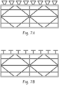
- FIG. 7A and FIG. 7B is a partial, cross-sectional view of an embodiment of a multiwall sheet including a noise reducing structure.
- the multiwall sheet of each of FIG. 7A and FIG. 7B includes three transverse walls within the multiwall sheet, a rib within the multiwall sheet, and dividers within the multiwall sheet, which are non-parallel and non-perpendicular to the walls and the ribs.
- FIG. 8A and FIG. 8B is a partial, cross-sectional view of an embodiment of a multiwall sheet including a noise reducing structure.
- the multiwall sheet of each of FIG. 8A and FIG. 8B includes three transverse walls within the multiwall sheet, a rib within the multiwall sheet, and dividers within the multiwall sheet, which are non-parallel and non-perpendicular to the walls and the ribs.
- the transverse walls can extend longitudinally the length of an upper wall and a lower wall of the multiwall sheet (e.g., extend between the upper wall and the lower wall, but not contact).
- the transverse walls can be parallel to the upper wall and the lower wall, or the transverse wall can be substantially parallel to the upper wall and the lower wall (e.g., not completely parallel across the entire length of the upper wall and the lower wall, but also not intersecting the upper wall or the lower wall, accommodating for slight variations in the orientation during processing).
- the multiwall sheet can have sinusoidal shaped dividers. It is contemplated that any suitable shape dividers could be used.
- the dividers can include a shape such as lamellar-shaped elements, triangular-shaped elements, pyramidal-shaped elements, cylindrical-shaped elements, conical-shaped elements, cubical-shaped elements, trapezoidal-shaped elements, sinusoidal-shaped elements, saw tooth-shaped elements, abs(sin)-shaped elements, cycloid-shaped elements, fiber shaped elements, or a combination thereof.
- a method of forming a noise reducing structure can include extruding a unitary structure including a plastic sheet (10) and a plastic noise reducer (100), e.g., in a direction along a z-axis, as disclosed herein.
- a method of forming a multiwall sheet including a noise reducer (100) can include extruding a multi wall sheet unitary structure including a first plastic wall (2), a second plastic wall (4), a first plastic rib (6), and a second plastic rib (8), e.g., in a direction along a z-axis, as disclosed herein; extruding a noise reducing unitary structure including a plastic sheet (10) and the plastic noise reducer (100), e.g., in a direction along the z-axis; applying the plastic (10) sheet of the noise reducing unitary structure to the first plastic wall (2) of the multiwall sheet unitary structure.
- a method of forming a multiwall sheet including a noise reducer (100) can include extruding a unitary structure including a first plastic wall (2), a second plastic wall (4), a first plastic rib (6), a second plastic rib (8), and the plastic noise reducer (100), e.g., in a direction along a z-axis, as disclosed herein.
- the noise reducer can extend linearly in the (positive or negative) z-axis direction (e.g., the noise reducer can be linear in the (positive or negative) z-axis direction) or the noise reducer can extend non-linearly in the (positive or negative) z-axis direction (e.g., the noise reducer can be non-linear in the (positive or negative) z-axis direction).
- a noise reducer extending linearly in the (positive or negative) z-axis direction e.g., the noise reducer being linear in the (positive or negative) z-axis direction
- the multiwall sheet can additionally include a clip located at an end of the multiwall sheet to facilitate attachment to a structure, frame enclosure for the multiwall sheet, or to another multiwall sheet.
- the multiwall sheet can, optionally, include a receiving end for a clip to attach thereto.
- the multiwall sheet When assembled, the multiwall sheet can be exposed to a variety of forces caused by snow, wind, rain, hail, and the like.
- the multiwall sheet is desirably capable of withstanding these forces without failing (e.g., buckling, cracking, bowing, and so forth).
- the specific dimensions of the multiwall sheet can be chosen so that the multiwall sheet can withstand these forces.
- Such a multiwall sheet as disclosed herein can provide desirable performance and be a low cost product.
- the multiwall sheet can be relatively lightweight and easy to install.
- the multiwall sheets disclosed herein can be used in a variety of applications, including, but not limited to, industrial roof and sidewalls, commercial greenhouses, sunroom, swimming pool, and conservatory roofing, shopping center roofing, railway/metro stations, football stadium roofing, and roof lights.
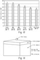
- FIG. 9 illustrates sound intensity levels of typical sounds. Sound intensity ranges from 0 to 140 decibels (dB). Excessive noise can negatively impact human health and behavior. Rain noise can be less than a normal conversation threshold (60 dB) on glass roof products and greater than a normal conversation threshold on multiwall sheet products, which can include a drum effect.
- "16 mm MWS” or “MWS 16 mm” in FIG. 11 is a 16 mm thick polycarbonate multiwall sheet with three layered/skins and tunnel structures.
- Glass DG” or “DG 6 /12/6" in FIG. 11 is a double-glazed glass with 6 mm thick outer glass sheets and a 12 mm airgap therebetween.
- Rain noise evaluation for a roof was normalized by ISO 140-18:2006, which was replaced by ISO 10140-5:2010/AMD1:2014, which was revised by ISO 10140-5:2021.
- the sound level is greater for "heavy” as compared to "intense rain.”
- Heavy rain parameters include rain drop diameters of 5 millimeters (mm), rainfall velocity of 7 meters per second (m/s), and rainfall rate of 40 millimeters per hour (mm/hr) and intense rain parameters include rain drop diameters of 2 mm, rainfall velocity of 4 m/s, and rainfall rate of 15 mm/hr.
- rain drop shapes can include paraboloid, cylindrical-hemispherical, ellipsoidal, and spherical; spherical is ideal for noise evaluation.
- Average sound intensity for various roof materials include 71 dBA for "Steel 0.5 mm" (0.5 mm thick corrugated steel roof sheet, 68 dBA for "MWS 16 mm", 65 dBA for "MWS 25 mm” (25 mm thick polycarbonate multiwall sheet with five layered/skins and a rectangular structure), 59 dBA for "Glass 6 mm” (6 mm thick single glass roof sheet), 56 dBA for "ETFE pillow” (Texlon ® ethylene tetrafluoroethylene (ETFE) rain suppresser available from Vector Foiltec GmbH), and 52 dBA "DG 6 /12/6.”
- Rain noise on multiwall sheets e.g., "MWS 16 mm” or “MWS 25 mm
- a recommended level e.g., 55 dBA.
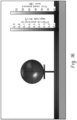
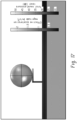
- a computational multiphysics predictive tool as shown in FIG. 13 is used characterize the operation and or quantify the performance.
- Acoustic Drum effect simulation involves, structural dynamics, Time domain to Frequency domain conversion, FFT, Acoustics and A-weighted prediction of sound level.
- Impact of a single rain drop on a solid sheet structure involves all three phases of liquid water drop, the solid sheet structure, and air acoustics. Interaction and coupling of all three physics are involved, computational fluid dynamics (CFD), computational structural mechanics (CSM), and acoustic modelling. In a virtual acoustic setup model, impact force, interaction with solid structure, and acoustics is modelled.
- CFD computational fluid dynamics
- CSM computational structural mechanics
- acoustic modelling In a virtual acoustic setup model, impact force, interaction with solid structure, and acoustics is modelled.
- rain impact force of spherical rain drops are modelled in time domain and converted to frequency domain.
- the frequency ranges from 100 hertz (Hz) to 3,150 Hz, at 100, 125, 160, 200, 250, 315, 400, 500, 630, 800, 1,000, 1,250, 1,600, 2,000, 2,500, and 3,150 Hz.
- Acoustic analysis is performed on a unit cell for sound intensity measurements due to rain drop impact.
- a periodic boundary condition represents full domain and heavy rainfall rate. Sound intensity is determined at the air domain. Sound intensity A-weighted levels are calculated for single point data.
- FIG. 15 is a simulation result showing contour plots that corresponds to a multiwall sheet without a noise reducing structure: ("Comparative Example 1").
- FIG. 16 is a simulation result showing contour plots that corresponds to a multiwall sheet including a noise reducing structure as shown in FIG. 1A and FIG. 1B ("Example 1") (with a closest distance between an end of the first plastic noise reducer (100a) and an end of the second plastic noise reducer (100b) of 2 mm).
- FIG 17 is a simulation result showing contour plots that corresponds to a multiwall sheet including a noise reducing structure as shown in FIG. 2 ("Example 2").
- FIG. 18 is a simulation result showing contour plots that corresponds to a multiwall sheet including a noise reducing structure as shown in FIG. 3A ("Example 3").
- FIG. 19 is a simulation result showing contour plots that corresponds to a multiwall sheet including a noise reducing structure as shown in FIG. 4A and FIG. 4B ("Example 4").
- FIG. 20 is a simulation result showing contour plots that corresponds to a multiwall sheet including a noise reducing structure as shown in FIG. 5A and FIG. 5B ("Example 5").
- the contour plots show rain drop acceleration magnitude in meters per square seconds (m/s 2 ) and acoustic sound pressure in the multiwall sheets in decibels (dB) at 500 Hz frequency.
- the sound level transmitted are lower for all multiwall sheets including a noise reducing structure.
- the frequency range is from 100 to 3,150 Hz.
- FIGS. 15-20 show intermediate results leading to the calculation of dBA in FIG. 21 .
- FIG. 21 is a graph of sound intensity (decibels (dB) versus frequency (hertz (Hz)) showing results for Comparative Example 1-3 and Examples 1-5.
- Comparative Example 1 exhibited an average sound intensity of 77 dB.
- Comparative Example 2-3 exhibited an average sound intensity of 87.1 and 79.1 dB, respectively.
- Example 2 and 3 are examples of rain noise amplifier.
- Examples 1-5 exhibited average sound intensities of 53.3 dB, 49.7 dB, 43.5 dB, 43.3 dB, and 29.3 dB, respectively.
- Comparative Example 2 is similar to Example 1, but with each of the first portion (110) and the second portion (120) having a thickness of 2 mm, which was greater than the thickness of the plastic sheet (10), which was 1 mm.
- Comparative Example 1 is similar to Example 1, but with the first portion (110) having a thickness of 2 mm, which was greater than a thickness of the plastic sheet (10) and without the second portion (120).
- a noise reducing structure comprises a plastic sheet (10) comprising a first surface (11) extending along a z-axis and extending along an x-axis, the x axis being orthogonal to the z-axis; and a second surface (12) extending along the z-axis and extending along the x-axis, the second surface (12) being opposite the first surface; and a plastic noise reducer (100) extending along the z-axis, wherein the plastic noise reducer (100) comprises a first portion (110) extending from the first surface (11) forming an angle ⁇ with the first surface, and a second portion (120) extending from a first end the first portion (110) forming an angle ⁇ with the first portion (110).
- a method of forming the noise reducing structure comprises extruding a unitary structure comprising the plastic sheet (10) and the plastic noise reducer (100) in a direction along the z-axis.
- a multiwall sheet comprises a first plastic wall (2) extending along a z-axis and extending along an x-axis, the x-axis being orthogonal to the z-axis; a second plastic wall (4) extending along the z-axis and extending along the x-axis, the second plastic wall (4) being spaced apart from the first wall (2) along a y-axis, the y-axis being orthogonal to the z-axis and the x-axis; a first plastic rib (6) extending along the z-axis and extending along the y-axis between the first wall (2) and the second wall (4); a second plastic rib (8) extending along the z-axis and extending along the y-axis between the first wall (2) and the second wall (4), the second rib (8) being spaced apart from the first rib (6) along the x-axis; and the noise reducing structure, wherein the plastic sheet (10) is on a surface of the plastic sheet (
- a method of forming the multiwall sheet comprises extruding a multiwall sheet unitary structure comprising the first plastic wall (2), the second plastic wall (4), the first plastic rib (6), and the second plastic rib (8) in a direction along the z-axis; extruding a noise reducing unitary structure comprising the plastic sheet (10) and the plastic noise reducer (100) in a direction along the z-axis; and applying the plastic sheet (10) of the noise reducing unitary structure to the first plastic wall (2) of the multiwall sheet unitary structure.
- a multiwall sheet comprises a first plastic wall (2) extending along a z-axis and extending along an x-axis, the x-axis being orthogonal to the z-axis; a second plastic wall (4) extending along the z-axis and extending along the x-axis, the second plastic wall (4) being spaced apart from the first wall (2) along a y-axis, the y-axis being orthogonal to the z-axis and the x-axis; a first plastic rib (6) extending along the z-axis and extending along the y-axis between the first wall (2) and the second wall (4); a second plastic rib (8) extending along the z-axis and extending along the y-axis between the first wall (2) and the second wall (4), the second rib (8) being spaced apart from the first rib (6) along the x-axis; and a plastic noise reducer (100) extending along the z-axis, where
- a method of forming the multi wall sheet comprises extruding a unitary structure comprising the first plastic wall (2), the second plastic wall (4), the first plastic rib (6), the second plastic rib (8), and the plastic noise reducer (100) in a direction along the z-axis.
- the term "unitary,” “monolith,” or “monolithic,” for example, a unitary component or a monolith or monolithic structure, refers to a three-dimensional construction, e.g., one body, that can be formed from portions that can have substantially identical or identical compositions.
- a monolith can be made of a single, continuous material, e.g., thermoplastic material, and can be manufactured using various techniques, including injection molding, compression molding, and extrusion. Accordingly, a unitary component differs from a laminate or assembly of differing constituents, which includes an interface between differing constituents thereof.
- a unitary component can be integrally formed, for example, integrally molded in a single mold.
- portions can be “integrally formed,” or one portion can be “integrally formed” with a different portion, resulting in a unitary component differing from a laminate or assembly of differing constituents, which includes an interface between differing constituents thereof.
- Exemplary embodiments are described herein with reference to cross section illustrations that are schematic illustrations of idealized embodiments. As such, variations from the shapes of the illustrations as a result, for example, of manufacturing techniques and/or tolerances, are to be expected. Thus, embodiments described herein should not be construed as limited to the particular shapes of regions as illustrated herein but are to include deviations in shapes that result, for example, from manufacturing. For example, a region illustrated or described as flat may, typically, have rough and/or nonlinear features. Moreover, sharp angles that are illustrated may be rounded. Thus, the regions illustrated in the figures are schematic in nature and their shapes are not intended to illustrate the precise shape of a region and are not intended to limit the scope of the present claims.
- test standards are the most recent standard in effect as of the filing date of this application, or, if priority is claimed, the filing date of the earliest priority application in which the test standard appears.
Landscapes
- Engineering & Computer Science (AREA)
- Architecture (AREA)
- Civil Engineering (AREA)
- Structural Engineering (AREA)
- Physics & Mathematics (AREA)
- Acoustics & Sound (AREA)
- Multimedia (AREA)
- Soundproofing, Sound Blocking, And Sound Damping (AREA)
Abstract
A noise reducing structure includes a plastic sheet (10) including a first surface (11) extending along a z-axis and extending along an x-axis, the x-axis being orthogonal to the z-axis; and a second surface (12) extending along the z-axis and extending along the x-axis, the second surface (12) being opposite the first surface; and a plastic noise reducer (100) extending along the z-axis, wherein the plastic noise reducer (100) includes a first portion (110) extending from the first surface (11) forming an angle α with the first surface, and a second portion (120) extending from a first end the first portion (110) forming an angle β with the first portion (110).
Description
- Disclosed herein are rain noise reducers, and more particularly multiwall sheets including rain noise reducers, e.g., for use in industrial applications.
- In the construction of naturally lit structures (e.g., greenhouses, pool enclosures, conservatories, stadiums, sunrooms, and so forth), glass has been employed in many applications as transparent structural elements, such as, windows, facings, and roofs. However, polymer sheeting is replacing glass in many applications due to several notable benefits.
- One benefit of polymer sheeting is that it exhibits excellent impact resistance compared to glass. This in turn reduces breakage and hence, maintenance costs in applications wherein vandalism, hail, contraction/expansion, and so forth, is encountered. Another benefit of polymer sheeting is a significant reduction in weight compared to glass. This makes polymer sheeting easier to install than glass and reduces the load-bearing requirements of the structure on which they are installed.
- In addition to these benefits, one of the most significant advantages of polymer sheeting is that it provides improved insulative properties compared to glass. This characteristic significantly affects the overall market acceptance of polymer sheeting as consumers desire structural elements with improved efficiency to reduce heating and/or cooling costs. Although the insulative properties of polymer sheeting are greater than that of glass, it is challenging to have a low thermal insulation value, high stiffness (i.e., rigidity), and light transmission in polymer sheeting. Thus, there is a continuous demand for further improvement.
- Multiwall sheets can be designed for structural and thermal insulation applications. As mentioned, higher thermal insulation values are continually sought in the industry for multiwall sheet applications. Sound pollution, for example, from rain, is a concern; for example, rain drops impacting an exposed surface of a multiwall sheet can cause a drum effect, which can be loud.
- Thus, there is a need for multiwall sheets that provide decreased rain noise. There is also a need for multiwall sheets that provide decreased rain noise without minimal or no impact on the overall transparency of the multiwall sheet. Additionally, multiwall sheets that provide decreased rain noise and that can be produced without an increase in manufacturing steps and thus cost, are also desired.
- Disclosed, in various embodiments, are rain noise reducers, noise reducing structures, and multiwall sheets and methods for making and using the same.
- In an embodiment, a noise reducing structure comprises a plastic sheet (10) comprising a first surface (11) extending along a z-axis and extending along an x-axis, the x axis being orthogonal to the z-axis; and a second surface (12) extending along the z-axis and extending along the x-axis, the second surface (12) being opposite the first surface; and a plastic noise reducer (100) extending along the z-axis, wherein the plastic noise reducer (100) comprises a first portion (110) extending from the first surface (11) forming an angle α with the first surface, and a second portion (120) extending from a first end the first portion (110) forming an angle β with the first portion (110).
- In an embodiment, a multiwall sheet comprises a first plastic wall (2) extending along a z-axis and extending along an x-axis, the x-axis being orthogonal to the z-axis; a second plastic wall (4) extending along the z-axis and extending along the x-axis, the second plastic wall (4) being spaced apart from the first wall (2) along a y-axis, the y-axis being orthogonal to the z-axis and the x-axis; a first plastic rib (6) extending along the z-axis and extending along the y-axis between the first wall (2) and the second wall (4); a second plastic rib (8) extending along the z-axis and extending along the y-axis between the first wall (2) and the second wall (4), the second rib (8) being spaced apart from the first rib (6) along the x-axis; and a plastic noise reducer (100) extending along the z-axis, wherein the plastic noise reducer (100) comprises a first portion (110) extending from the first plastic wall (2) in a direction away from the second plastic wall (4) forming an angle α with the first plastic wall (2), and a second portion (120) extending from a first end the first portion (110) forming an angle β with the first portion (110).
- These and other features and characteristics are more particularly described below.
- The following is a brief description of the drawings wherein like elements are numbered alike and which are presented for the purposes of illustrating the exemplary embodiments disclosed herein and not for the purposes of limiting the same.
- A more complete understanding of the components, processes, and apparatuses disclosed herein can be obtained by reference to the accompanying drawings. These figures (also referred to herein as "FIG.") are merely schematic representations based on convenience and the ease of demonstrating the present disclosure, and are, therefore, not intended to indicate relative size and dimensions of the devices or components thereof and/or to define or limit the scope of the exemplary embodiments. Although specific terms are used in the following description for the sake of clarity, these terms are intended to refer only to the particular structure of the embodiments selected for illustration in the drawings, and are not intended to define or limit the scope of the disclosure.
-
FIG. 1A is a partial, cross-sectional view of an embodiment of a noise reducing structure; -
FIG. 1B is an enlarged view of the noise reducing structure shown inFIG. 1A ; -
FIG. 2 is a partial, cross-sectional view of an embodiment of a noise reducing structure; -
FIG. 3A is a partial, cross-sectional view of an embodiment of a noise reducing structure; -
FIG. 3B is a partial, cross-sectional view of an embodiment of a noise reducing structure; -
FIG. 3C is a partial, cross-sectional view of an embodiment of a noise reducing structure; -
FIG. 4A is a partial, cross-sectional view of an embodiment of a noise reducing structure; -
FIG. 4B is an enlarged view of the noise reducing structure shown inFIG. 4A ; -
FIG. 5A is a partial, cross-sectional view of an embodiment of a noise reducing structure; -
FIG. 5B is an enlarged view of the noise reducing structure shown inFIG. 5A ; -
FIG. 6A is a partial, cross-sectional view of an embodiment of a multiwall sheet including multiple noise reducers; -
FIG. 6B is a partial, cross-sectional view of an embodiment of a multiwall sheet including multiple noise reducers; -
FIG. 7A is a partial, cross-sectional view of an embodiment of a multiwall sheet including multiple noise reducers; -
FIG. 7B is a partial, cross-sectional view of an embodiment of a multiwall sheet including multiple noise reducers; -
FIG. 8A is a partial, cross-sectional view of an embodiment of a multiwall sheet including multiple noise reducers; -
FIG. 8B is a partial, cross-sectional view of an embodiment of a multiwall sheet including multiple noise reducers; -
FIG. 9 is a graph of sound intensity level of typical sounds; -
FIG. 10 shows different rain drop shapes; -
FIG. 11 is a graph of sound intensity (decibels (dB)) versus frequency (hertz (Hz)) for different products; -
FIG. 12 is a graph of average sound intensity (dB) for the different products ofFIG. 3A ; -
FIG. 13 shows a virtual acoustic set-up for rain noise measurement; -
FIG. 14 is a graph of sound intensity (dB) versus frequency (Hz), comparing experimental data and simulation results; -
FIG. 15 shows simulation results for Comparative Example 1 with no noise reducer; -
FIG. 16 shows simulation results for the noise reducer shown inFIG. 1A and FIG. 1B ; -
FIG. 17 shows simulation results for the noise reducer shown inFIG. 2 ; -
FIG. 18 shows simulation results for the noise reducer shown inFIG. 3A ; -
FIG. 19 shows simulation results for the noise reducer shown inFIG. 4A and FIG. 4B ; -
FIG. 20 shows simulation results for the noise reducer shown inFIG. 5A and FIG. 5B ; and -
FIG. 21 is a graph of sound intensity (dB) versus frequency (Hz) for Comparative Example 1 and Examples 1-5. - Disclosed herein are rain noise reducers, noise reducing structures, and multiwall sheets and methods of making the same. Multiwall sheets including the disclosed acoustic rain noise reducers exhibit decreased rain noise as compared to multiwall sheets not including the disclosed rain noise reducers. Sound pollution is a key concern in certain applications and thus, multiwall sheets with decreased rain noise are desired. A one or two decibel (dB) decreased in rain noise loss can be considered a significant improvement. The rain noise reducers, noise reducing structures, and multiwall sheets disclosed herein can exhibit a sound intensity of less than or equal to 60 dBA, or less than 60 dBA, or less than or equal to 55 dBA, or less than 55 dBA, or less than 45 dBA, as measured by ISO 10140 5:2021.
- A-weighting is a sound pressure level measurement, defined in the International standard IEC 61672-1:2013 and various national standards. A-weighting is applied to measured sound levels in an effort to account for the relative loudness perceived by the human ear. A-weighting is employed by arithmetically adding a table of values, listed by octave or third-octave bands, to the measured sound pressure levels in decibels (dB). The resulting octave band measurements are added logarithmically to provide a single A weighted value, in dB(A) or dBA units.
- Hearing sound levels above 70 dB for prolonged time can cause several physiological and psychological health issues such as anxiety, hypertension and delayed cognitive development in children, pain and injury to ear or even complete hearing loss. Even at low levels, noise produced inside buildings by rainfall impacting a roof of the building can interfere with normal activities by disturbing the speech intelligibility. The World Health Organization (WHO) recommends noises below 70 dB over 24 hours to prevent noise induced hearing losses and the Environmental Protection Agency (EPA) specifies limits for 55 dB for outdoors and 45 dB for indoors. Allowable or recommended decibel limits include 55 dBA during daytime and 45 dBA during nighttime in residential and commercial areas and 75 dBA during daytime and 70 dBA during nighttime in industrial areas.
- Rainfall noise is considered a significant problem, and ISO 140-18 published in 2006, provides guidelines for rain noise prediction and is updated by ISO 10140-5:2021. Natural rainfall is random. For measurement, ISO 140-18 specifies the following type of artificial rain.
Table 1 Rainfall type Rain drop diameter (millimeters (mm)) Rainfall velocity (meters per second (m/s)) Rainfall rate (millimeters per hour (mm/hr)) Intense 2 4 15 Heavy 5 7 40 - The forces produced when rain drops impact on a roof can be a significant source of noise. The forces produced by the rain drop impacts induce vibration in the roof structure producing sound, which can be very disruptive to the occupants below. Due to the difficulty and uncertainty in experimental rainfall noise measurement, computational multiphysics predictive tools are often used. The accurate prediction of rainfall noise, to mitigate noise issue, requires several phenomena to be accurately addressed, such us noise source and radiation. The mechanical excitation by rainfall depends on numerous parameters, such as rainfall rate, drop size, rain drop velocity, and acoustic radiation from the impact surface.
- Rain noise reduction can be achieved by dissipating energy resulting from rain drops impacting an exposed surface of a multiwall sheet, without out amplifying. Noise reducers as herein described can dissipate such energy, diminishing or eliminating a drum effect resulting from rain drops impacting an exposed surface of a multiwall sheet, and achieve rain noise reduction. The dimensions of the noise reducers and distances between the noise reducers can be adjusted to capture all rain drops (e.g., from intense to heavy) and prevent such rain drops from directly contacting the exposed surface of the multiwall sheet during rainfall.
- The multiwall sheet can be formed from a plastic material, such as thermoplastic resins, thermosets, or a combination thereof. Possible thermoplastic resins that can be employed to form the multiwall sheet include, but are not limited to, oligomers, polymers, ionomers, dendrimers, copolymers such as graft copolymers, block copolymers (e.g., star block copolymers, random copolymers, etc.), or a combination thereof. Examples of such thermoplastic resins include, but are not limited to, polycarbonates (e.g., blends of polycarbonate (such as, polycarbonate-polybutadiene blends, copolyester polycarbonates)), polystyrenes (e.g., copolymers of polycarbonate and styrene, polyphenylene ether-polystyrene blends), polyimides (e.g., polyetherimides), acrylonitrile-styrene-butadiene (ABS), polyalkylmethacrylates (e.g., polymethylmethacrylates), polyesters (e.g., copolyesters, polythioesters), polyolefins (e.g., polypropylenes and polyethylenes, high density polyethylenes, low density polyethylenes, linear low density polyethylenes), polyamides (e.g., polyamideimides), polyarylates, polysulfones (e.g., polyarylsulfones, polysulfonamides), polyphenylene sulfides, polytetrafluoroethylenes, polyethers (e.g., polyether ketones, polyether etherketones, polyethersulfones), polyacrylics, polyacetals, polybenzoxazoles (e.g., polybenzothiazinophenothiazines, polybenzothiazoles), polyoxadiazoles, polypyrazinoquinoxalines, polypyromellitimides, polyquinoxalines, polybenzimidazoles, polyoxindoles, polyoxoisoindolines (e.g., polydioxoisoindolines), polytriazines, polypyridazines, polypiperazines, polypyridines, polypiperidines, polytriazoles, polypyrazoles, polypyrrolidines, polycarboranes, polyoxabicyclononanes, polydibenzofurans, polyphthalides, polyacetals, polyanhydrides, polyvinyls (e.g., polyvinyl ethers, polyvinyl thioethers, polyvinyl alcohols, polyvinyl ketones, polyvinyl halides, polyvinyl nitriles, polyvinyl esters, polyvinylchlorides), polysulfonates, polysulfides, polyureas, polyphosphazenes, polysilazzanes, polysiloxanes, or a combination thereof.
- In an embodiment, the plastic used in the multiwall sheet can include, but is not limited to, polycarbonate resins (e.g., Lexan* resins, commercially available from SABIC Innovative Plastics), polyphenylene ether-polystyrene resins (e.g., Noryl* resins, commercially available from SABIC Innovative Plastics), polyetherimide resins (e.g., Ultem* resins, commercially available from SABIC Innovative Plastics), polybutylene terephthalate-polycarbonate resins (e.g., Xenoy* resins, commercially available from SABIC Innovative Plastics), copolyestercarbonate resins (e.g. Lexan* SLX resins, commercially available from SABIC Innovative Plastics), or a combination thereof. In an embodiment, the thermoplastic resins can include, but are not limited to, homopolymers and copolymers of a polycarbonate, a polyester, a polyacrylate, a polyamide, a polyetherimide, a polyphenylene ether, or a combination thereof. The polycarbonate can include copolymers of polycarbonate (e.g., polycarbonate-polysiloxane, such as polycarbonate-polysiloxane block copolymer), linear polycarbonate, branched polycarbonate, end-capped polycarbonate (e.g., nitrile end-capped polycarbonate), or a combination thereof, for example, a combination of branched and linear polycarbonate.
- The multiwall sheet can include various additives ordinarily incorporated into polymer compositions of this type, with the proviso that the additive(s) are selected so as to not significantly adversely affect the desired properties of the multiwall sheet, in particular, sound transmission loss and desired degree of transparency. Such additives can be mixed at a suitable time during the mixing of the components for forming the multiwall sheet. Exemplary additives include impact modifiers, fillers, reinforcing agents, antioxidants, heat stabilizers, light stabilizers, ultraviolet (UV) light stabilizers, plasticizers, lubricants, mold release agents, antistatic agents, colorants (such as carbon black and organic dyes), surface effect additives, radiation stabilizers (e.g., infrared absorbing), flame retardants, diffusion barriers (e.g., gas and/or liquid barriers), and anti-drip agents. A combination of additives can be used, for example a combination of a heat stabilizer, mold release agent, and ultraviolet light stabilizer. The additives can be used in the amounts effective for providing the desired property (e.g., UV light stabilizers are effective for filtering UV and protecting the multi wall sheet from UV light). The total amount of additives (other than any impact modifier, filler, or reinforcing agents) can be 0.001 wt% to 5 wt%, based on the total weight of the composition of the multi wall sheet.
- In addition to sound transmission, the plastic material can be chosen to exhibit sufficient impact resistance such that the multiwall sheet is capable of resisting breakage (e.g., cracking, fracture, and the like) caused by impact (e.g., hail, birds, stones and so forth). Therefore, plastics exhibiting an impact strength greater than or equal to about 7.5 foot-pounds per square inch (ft-lb/in2) (4.00 Joules per square centimeter (J/cm2)), for example, greater than about 10.0 ft-lb/in2 (5.34 J/cm2) or greater than or equal to about 12.5 ft-lb/in2 (6.67 J/cm2) are desirable, as tested per ASTM D-256-93 (Izod Notched Impact Test). Further, desirably, the plastic has ample stiffness to allow for the production of a multiwall sheet that can be employed in applications wherein the multiwall sheet can be supported and/or clamped on two or more sides of the multiwall sheet (e.g., clamped on all four sides), such as in greenhouse applications including tubular steel frame construction. Sufficient stiffness herein is defined as polymers having a Young's modulus (e.g., modulus of elasticity) that is greater than or equal to about 1 x 10⁹ Newtons per square meter (N/m2), for example 1 x 10⁹ to 100 x 109 N/m2 or 2 x 10⁹ to 20 x 109 N/m2.
- The noise reducers can include any suitable material that will provide the desired decrease in rain noise, e.g., the noise reducers can include a material as described herein for the multiwall sheet. In an embodiment, a material of the noise reducers is the same as a material of the multiwall sheet. In an embodiment, a material of the noise reducers is different than a material of the multi wall sheet. A material of each of the noise reducers can independently be the same as a material of the multiwall sheet, different than a material of the multiwall sheet, the same as a material of other noise reducers, different than a material of other noise reducers, or a combination thereof.
- Polycarbonate, a material that can be used to make the multiwall sheet (e.g., the walls, ribs, or a combination thereof of the multiwall sheet), the noise reducer, or a combination thereof, can have a longitudinal velocity of sound of 2,300 meters per second (m/s), a shear wave sound velocity value of 1,250 m/s, and an acoustic impedance value of 2.75 megaRayleighs (MRayl), where one Rayleigh is equivalent to 1 kilogram per square meter second (kg/m2s). Air has a longitudinal velocity of sound of 334 m/s. Thermoplastic resins can have a longitudinal velocity of sound of 1,600 m/s to 2,800 m/s; a shear wave sound velocity of 500 m/s to 1,600 m/s; and an acoustic impedance value of 1.5 MRayl to 3 MRayl. Liquids can have a longitudinal velocity of sound of 750 m/s to 1,500 m/s and an acoustic impedance of 0.8 MRayl to 1.5 MRayl.
- A multiwall sheet that does not include the noise reducers can be transparent (e.g., the multiwall sheet can have greater than or equal to 25% light transmission). Transparency of a multiwall sheet including noise reducers can be less than the transparency of a multiwall sheet that does not include the noise reducers. For example, a multiwall sheet that does not include the noise reducers can have a transparency of greater than or equal to 85%, for example, greater than or equal to 90%, greater than or equal to 95%, greater than or equal to 96%, or greater than or equal to 99%, and transparency of a multiwall sheet including noise reducers can be greater than or equal to 1%, for example, greater than or equal to 5%.
- Percent transmission for laboratory scale samples can be determined using ASTM D1003-00, procedure B using CIE standard illuminant C. ASTM D-1003-00 (Procedure B, Spectrophotometer, using illuminant C with diffuse illumination with unidirectional viewing) defines transmittance as:

- wherein: I = intensity of the light passing through the test sample
- Io= Intensity of incident light.
- A multiwall sheet can be formed from various polymer processing methods, such as extrusion or injection molding, if produced as a unitary structure. Continuous production methods, such as extrusion, can offer improved operating efficiencies and greater production rates than non-continuous operations, such as injection molding. A single screw extruder can be employed to extrude a polymer melt (e.g., polycarbonate, such as Lexan*, commercially available from SABIC Innovative Plastics). The polymer melt is fed to a profile die capable of forming an extrudate having a cross-section of the multiwall sheet as disclosed and illustrated herein. The multiwall sheet travels through a sizing apparatus (e.g., vacuum bath including sizing dies) and is then cooled below its glass transition temperature (e.g., for polycarbonate, about 297°F (147°C)).
- After the panel has cooled, it can be cut to the desired length utilizing an extrusion cutter, such as an indexing in-line saw. Once cut, the multiwall sheet can be subjected to secondary operations before packaging. Exemplary secondary operations can include annealing, printing, attachment of fastening members, trimming, further assembly operations, and/or other desirable processes. The size of the extruder, as measured by the diameter of the screw of the extruder, is based upon the production rate desired and calculated from the volumetric production rate of the extruder and the cross-sectional area of the panel. The cooling apparatus can be sized (e.g., length) to remove heat from the extrudate in an expeditious manner without imparting haze.
- Haze can be imparted when a polymer (e.g., polycarbonate) is cooled rapidly. Therefore, the cooling apparatus can operate at warmer temperatures (e.g., greater than or equal to about 100°F (39°C), for example, greater than or equal to 125°F (52°C), rather than colder temperatures (e.g., less than 100°F (39°C), for example, less than or equal to about 75°F (24°C)) to reduce hazing. If warmer temperatures are employed, the bath length can be increased to allow ample time to reduce the temperature of the extrudate below its glass transition temperature. The size of the extruder, cooling capacity of the cooling apparatus, and cutting operation can be capable of producing the multiwall sheet at a rate of greater than or equal to 5 feet per minute (ft/min) (1.5 meters per minute (m/min)). However, production rates of greater than 10 ft/min (3 m/min), or greater than 15 ft/min (4.6 m/min) can be achieved if such rates are capable of producing surface features that include the desired attributes.
- Co-extrusion methods can also be employed for the production of the multiwall sheet. Co-extrusion can be employed to supply different polymers to a portion of the geometry of the multi wall sheet to improve and/or alter the performance of the multi wall sheet and/or to reduce raw material costs. One skilled in the art would readily understand the versatility of the process and the myriad of applications in which co-extrusion can be employed in the production of multiwall sheets.
- In an embodiment, a method of reducing raise noise that can otherwise result from rain drops impacting a multiwall sheet can include forming a multiwall sheet including a noise reducers. In an embodiment, a method of reducing raise noise that can otherwise result from rain drops impacting a multiwall sheet can include forming a noise reducing structure including noise reducers and attaching the noise reducing structure including noise reducers to a multiwall sheet.
-
FIG. 1A illustrates a noise reducing structure (1000) including a plastic sheet (10) including a first surface (11) extending along a z-axis and extending along an x-axis, the x-axis being orthogonal to the z-axis; and a second surface (12) extending along the z-axis and extending along the x-axis, the second surface (12) being opposite the first surface. The noise reducing structure (1000) further includes a plastic noise reducer (100) extending along the z-axis. The plastic noise reducer (100) includes a first portion (110) extending from the first surface (11) forming an angle α with the first surface (11), and a second portion (120) extending from a first end (110a) the first portion (110) forming an angle β with the first portion (110). The plastic noise reducer (100) can include a third portion (130) extending from an intersection of the first portion (110) and the second portion (12). The second portion (120) can be parallel to the first surface (11). - The angle α formed between the first portion (110) and the first surface (11) can be 15 to 165° or 45 to 135° or 80 to 100°, for example, 90°. The angle β formed between the second portion (120) and the first portion (110) can be 15 to 165° or 45 to 135° or 80 to 100°, for example, 90°.
-
FIG. 1B is an enlarged view of the noise reducing structure shown inFIG. 1A . As shown inFIG. 1B , a thickness of the plastic sheet (10) (e.g., a distance between the first surface (11) and the second surface (12)) can be 0.1 mm to 5 mm, for example, 1 mm. A distance between first portions (110) of a first plastic noise reducer (100a) and an adjacent second plastic noise reducer (100b) can be 2 mm to 5 mm, for example, 5 mm. A length of the first portion (110) (e.g., a distance from the first surface (11) to the second portion (120)) can be 1 mm to 2.5 mm, for example, 2.5 mm. A thickness of the second portion (120), the third portion (130), or each of the second portion (120) and the third portion (130) can be less than the thickness of the plastic sheet (10), for example, 0.25 mm. - A closest distance between an end of a first plastic noise reducer (100a) and an end of a second plastic noise reducer (100b) (e.g., a distance between an end of a second portion (120) of a first plastic noise reducer (100a) and an end of a third portion (130) of a second plastic noise reducer (100b)) can be 1 to 2 mm, for example, 2 mm (e.g., less than a radius of a large rain drop). A combined length of the second portion (120) and the third portion (130) can be 3 mm (e.g., a sum of the closest distance between an end of a first plastic noise reducer (100a) and an end of a second plastic noise reducer (100b) and the combined length of the second portion (120) and the third portion (130) can catch rain drops of all sizes). The second portion (120) and the third portion (130) can be equal in length or can be different lengths. In an embodiment, the second portion (120) and the third portion (130) are parallel to the first surface (11).
-
FIG. 2 illustrates a noise reducing structure (2000) similar to the noise reducing structure shown inFIG. 1A and FIG. 1B , but without the third portion (130). The angle α formed between the first portion (110) and the first surface (11) can be 15 to 165° or 45 to 135° or 80 to 100°, for example, 90°. The angle β formed between the second portion (120) and the first portion (110) can be 15 to 165° or 45 to 135° or 80 to 100°, for example, 90°. - Similar to the noise reducing structure shown in
FIG. 1A and FIG. 1B , a thickness of the plastic sheet (10) (e.g., a distance between the first surface (11) and the second surface (12)) can be 1 mm. A distance between first portions (110) of a first plastic noise reducer (200a) and an adjacent second plastic noise reducer (200b) can be 5 mm. A length of the first portion (110) (e.g., a distance from the first surface (11) to the second portion (120)) can be 2.5 mm. A thickness of the second portion (120) can be less than the thickness of the plastic sheet (10), for example, 0.25 mm. A closest distance between an end of a first plastic noise reducer (200a) and an end of a second plastic noise reducer (200b) can be 1 to 2 mm. A length of the second portion (120) can be 1.5 mm. -
FIG. 3A illustrates a noise reducing structure (3000) similar to the noise reducing structure shown inFIG. 2 , but with an angle α between 35 to 55° of about 45°, and an angle β between 35 to 55° of about 45°. Similar to the noise reducing structure shown inFIG. 2 , a thickness of the plastic sheet (10) (e.g., a distance between the first surface (11) and the second surface (12)) can be 1 mm. A distance between first portions (110) of a first plastic noise reducer (300a) and an adjacent second plastic noise reducer (300b) can be 5 mm. A length of the first portion (110) (e.g., a distance from the first surface (11) to the second portion (120)) can be 2.5 mm. A thickness of the second portion (120) can be less than the thickness of the plastic sheet (10), for example, 0.25 mm. A closest distance between an end of a first plastic noise reducer (300a) and an end of a second plastic noise reducer (300b) can be 1 to 2 mm. A length of the second portion (120) can be 1.5 mm.FIG. 3B illustrates a noise reducing structure (3100) andFIG. 3C illustrates a noise reducing structure (3200). -
FIG. 4A illustrates a noise reducing structure (4000) including a plastic sheet (10) including a first surface (11) extending along a z-axis and extending along an x-axis, the x-axis being orthogonal to the z-axis; and a second surface (12) extending along the z-axis and extending along the x-axis, the second surface (12) being opposite the first surface. The noise reducing structure (4000) further includes a plastic noise reducer (400) extending along the z-axis. The plastic noise reducer (400) includes a first portion (110) extending from the first surface (11) forming an angle α with the first surface (11), and a second portion (120) extending from a first end (110a) the first portion (110) forming an angle β with the first portion (110). The plastic noise reducer (400) can include a return portion (140) extending from the first surface (11) and connected to a second end (120b) of the second portion (120) not connected to the first portion (110). The angle α formed between the first portion (110) and the first surface (11) can be 15 to 165° or 45 to 135° and the angle β formed between the second portion (120) and the first portion (110) can be 15 to 165° or 45 to 135°. -
FIG. 4B is an enlarged view of the noise reducing structure shown inFIG. 4A . As shown inFIG. 4B , a thickness of the plastic sheet (10) (e.g., a distance between the first surface (11) and the second surface (12)) can be 1 mm. A shortest distance from the first surface (11) to the second portion (120) can be 2.5 mm (e.g., less than a radius of heavy rain drops). A thickness of the second portion (120) can be less than the thickness of the plastic sheet (10), for example, 0.25 mm. The dimensions of the plastic noise reducers (400) and distances between the plastic noise reducers (400) can be adjusted to capture all rain drops (e.g., from intense to heavy) and prevent such rain drops from directly contacting the first surface (11) during rainfall. - The first portion (110), the second portion (120), and the return portion (140) can form a symmetric shape. A distance between the first portion (110) and the return portion (140) along the first surface can be greater than a length of the second portion (120).
-
FIG. 5A illustrates a noise reducing structure (5000) similar to the noise reducing structure shown inFIG. 4A and FIG. 4B , but a distance between the first portion (110) and the return portion (140) along the first surface being less than a length of the second portion (120).FIG. 5B is an enlarged view of the noise reducing structure shown inFIG. 5A . As shown inFIG. 5B , a thickness of the plastic sheet (10) (e.g., a distance between the first surface (11) and the second surface (12)) can be 1 mm. A shortest distance from the first surface (11) to the second portion (120) can be 2.5 mm. A thickness of the second portion (120) can be less than the thickness of the plastic sheet (10), for example, 0.25 mm. - The plastic noise reducers shown in
FIGS. 4, 4A ,5, and 5A are hollow. Such a hollow shape can be formed by extrusion, as disclosed herein, and differentiates over a solid projection protruding from a surface of a plastic sheet or on a surface of a plastic sheet. - Plastic noise reducers as disclosed herein can extend along an entire length of plastic sheet, e.g., in a direction along a z-axis. Plastic noise reducers extending along an entire length of plastic sheet in a direction along a z-axis can be formed by extrusion, as disclosed herein.
- Each of
FIG. 6A and FIG. 6B is a partial, cross-sectional view of an embodiment of a multiwall sheet including a noise reducing structure. The multiwall sheet of each ofFIG. 6A and FIG. 6B includes a transverse wall within the multiwall sheet and a rib within the multiwall sheet. - Each of
FIG. 7A and FIG. 7B is a partial, cross-sectional view of an embodiment of a multiwall sheet including a noise reducing structure. The multiwall sheet of each ofFIG. 7A and FIG. 7B includes three transverse walls within the multiwall sheet, a rib within the multiwall sheet, and dividers within the multiwall sheet, which are non-parallel and non-perpendicular to the walls and the ribs. - Each of
FIG. 8A and FIG. 8B is a partial, cross-sectional view of an embodiment of a multiwall sheet including a noise reducing structure. The multiwall sheet of each ofFIG. 8A and FIG. 8B includes three transverse walls within the multiwall sheet, a rib within the multiwall sheet, and dividers within the multiwall sheet, which are non-parallel and non-perpendicular to the walls and the ribs. - With reference to
FIG. 6A, FIG. 6B ,FIG. 7A, FIG. 7B ,FIG. 8A, and FIG. 8B , in an embodiment, the transverse walls can extend longitudinally the length of an upper wall and a lower wall of the multiwall sheet (e.g., extend between the upper wall and the lower wall, but not contact). In an embodiment, the transverse walls can be parallel to the upper wall and the lower wall, or the transverse wall can be substantially parallel to the upper wall and the lower wall (e.g., not completely parallel across the entire length of the upper wall and the lower wall, but also not intersecting the upper wall or the lower wall, accommodating for slight variations in the orientation during processing). - The multiwall sheet can have sinusoidal shaped dividers. It is contemplated that any suitable shape dividers could be used. For example, the dividers can include a shape such as lamellar-shaped elements, triangular-shaped elements, pyramidal-shaped elements, cylindrical-shaped elements, conical-shaped elements, cubical-shaped elements, trapezoidal-shaped elements, sinusoidal-shaped elements, saw tooth-shaped elements, abs(sin)-shaped elements, cycloid-shaped elements, fiber shaped elements, or a combination thereof.
- A method of forming a noise reducing structure can include extruding a unitary structure including a plastic sheet (10) and a plastic noise reducer (100), e.g., in a direction along a z-axis, as disclosed herein. A method of forming a multiwall sheet including a noise reducer (100) can include extruding a multi wall sheet unitary structure including a first plastic wall (2), a second plastic wall (4), a first plastic rib (6), and a second plastic rib (8), e.g., in a direction along a z-axis, as disclosed herein; extruding a noise reducing unitary structure including a plastic sheet (10) and the plastic noise reducer (100), e.g., in a direction along the z-axis; applying the plastic (10) sheet of the noise reducing unitary structure to the first plastic wall (2) of the multiwall sheet unitary structure. A method of forming a multiwall sheet including a noise reducer (100) can include extruding a unitary structure including a first plastic wall (2), a second plastic wall (4), a first plastic rib (6), a second plastic rib (8), and the plastic noise reducer (100), e.g., in a direction along a z-axis, as disclosed herein.
- With regard to the noise reducer extending along the z-axis, the noise reducer can extend linearly in the (positive or negative) z-axis direction (e.g., the noise reducer can be linear in the (positive or negative) z-axis direction) or the noise reducer can extend non-linearly in the (positive or negative) z-axis direction (e.g., the noise reducer can be non-linear in the (positive or negative) z-axis direction). A noise reducer extending linearly in the (positive or negative) z-axis direction (e.g., the noise reducer being linear in the (positive or negative) z-axis direction) can ease or improve manufacturability thereof, for example, by extrusion.
- Optionally, the multiwall sheet can additionally include a clip located at an end of the multiwall sheet to facilitate attachment to a structure, frame enclosure for the multiwall sheet, or to another multiwall sheet. The multiwall sheet can, optionally, include a receiving end for a clip to attach thereto.
- When assembled, the multiwall sheet can be exposed to a variety of forces caused by snow, wind, rain, hail, and the like. The multiwall sheet is desirably capable of withstanding these forces without failing (e.g., buckling, cracking, bowing, and so forth). The specific dimensions of the multiwall sheet can be chosen so that the multiwall sheet can withstand these forces.
- Such a multiwall sheet as disclosed herein can provide desirable performance and be a low cost product. The multiwall sheet can be relatively lightweight and easy to install. The multiwall sheets disclosed herein can be used in a variety of applications, including, but not limited to, industrial roof and sidewalls, commercial greenhouses, sunroom, swimming pool, and conservatory roofing, shopping center roofing, railway/metro stations, football stadium roofing, and roof lights.
- The following examples are merely illustrative of the device disclosed herein and are not intended to limit the scope hereof. All of the following examples were based upon simulations unless specifically stated otherwise.
-
FIG. 9 illustrates sound intensity levels of typical sounds. Sound intensity ranges from 0 to 140 decibels (dB). Excessive noise can negatively impact human health and behavior. Rain noise can be less than a normal conversation threshold (60 dB) on glass roof products and greater than a normal conversation threshold on multiwall sheet products, which can include a drum effect. "16 mm MWS" or "MWS 16 mm" inFIG. 11 is a 16 mm thick polycarbonate multiwall sheet with three layered/skins and tunnel structures. "Glass DG" or "DG 6 /12/6" inFIG. 11 is a double-glazed glass with 6 mm thick outer glass sheets and a 12 mm airgap therebetween. - Rain noise evaluation for a roof was normalized by ISO 140-18:2006, which was replaced by ISO 10140-5:2010/AMD1:2014, which was revised by ISO 10140-5:2021. The sound level is greater for "heavy" as compared to "intense rain." Heavy rain parameters include rain drop diameters of 5 millimeters (mm), rainfall velocity of 7 meters per second (m/s), and rainfall rate of 40 millimeters per hour (mm/hr) and intense rain parameters include rain drop diameters of 2 mm, rainfall velocity of 4 m/s, and rainfall rate of 15 mm/hr. As shown in
FIG. 10 , rain drop shapes can include paraboloid, cylindrical-hemispherical, ellipsoidal, and spherical; spherical is ideal for noise evaluation. - With reference to
FIG. 11 andFIG. 12 , rain noise on various products was measured. Average sound intensity for various roof materials include 71 dBA for "Steel 0.5 mm" (0.5 mm thick corrugated steel roof sheet, 68 dBA for "MWS 16 mm", 65 dBA for "MWS 25 mm" (25 mm thick polycarbonate multiwall sheet with five layered/skins and a rectangular structure), 59 dBA for "Glass 6 mm" (6 mm thick single glass roof sheet), 56 dBA for "ETFE pillow" (Texlon® ethylene tetrafluoroethylene (ETFE) rain suppresser available from Vector Foiltec GmbH), and 52 dBA "DG 6 /12/6." Rain noise on multiwall sheets (e.g., "MWS 16 mm" or "MWS 25 mm") can be greater than rain noise on glass products, and can be greater than a recommended level (e.g., 55 dBA). - A computational multiphysics predictive tool, as shown in
FIG. 13 is used characterize the operation and or quantify the performance. Acoustic Drum effect simulation, involves, structural dynamics, Time domain to Frequency domain conversion, FFT, Acoustics and A-weighted prediction of sound level. - A simulation was conducted based on heavy rainfall of 40 millimeters per hour (mm/hr), 200 rain drops per square meter (m2), each rain drop having a diameter of 5 millimeters (mm) and a velocity of 7 meters per second (m/s) (kinetic energy of 0.001571451 newton-meter (N-m) and providing a force of 0.94 newtons (N)). Impact of a single rain drop on a solid sheet structure involves all three phases of liquid water drop, the solid sheet structure, and air acoustics. Interaction and coupling of all three physics are involved, computational fluid dynamics (CFD), computational structural mechanics (CSM), and acoustic modelling. In a virtual acoustic setup model, impact force, interaction with solid structure, and acoustics is modelled.
- With reference to
FIG. 13 , rain impact force of spherical rain drops are modelled in time domain and converted to frequency domain. The frequency ranges from 100 hertz (Hz) to 3,150 Hz, at 100, 125, 160, 200, 250, 315, 400, 500, 630, 800, 1,000, 1,250, 1,600, 2,000, 2,500, and 3,150 Hz. Acoustic analysis is performed on a unit cell for sound intensity measurements due to rain drop impact. A periodic boundary condition represents full domain and heavy rainfall rate. Sound intensity is determined at the air domain. Sound intensity A-weighted levels are calculated for single point data. - With reference to
FIG. 14 , measured and simulation results from 6 mm thick glass were compared. The measured/experimental average sound intensity was 59 dB and the simulated average sound intensity was 58.6 dB, indicating good correlation between the simulation results and experimental data. - Computational experiments were performed per ISO 10140-5:2021.
FIG. 15 is a simulation result showing contour plots that corresponds to a multiwall sheet without a noise reducing structure: ("Comparative Example 1").FIG. 16 is a simulation result showing contour plots that corresponds to a multiwall sheet including a noise reducing structure as shown inFIG. 1A and FIG. 1B ("Example 1") (with a closest distance between an end of the first plastic noise reducer (100a) and an end of the second plastic noise reducer (100b) of 2 mm).FIG 17 . is a simulation result showing contour plots that corresponds to a multiwall sheet including a noise reducing structure as shown inFIG. 2 ("Example 2").FIG. 18 is a simulation result showing contour plots that corresponds to a multiwall sheet including a noise reducing structure as shown inFIG. 3A ("Example 3").FIG. 19 is a simulation result showing contour plots that corresponds to a multiwall sheet including a noise reducing structure as shown inFIG. 4A and FIG. 4B ("Example 4").FIG. 20 is a simulation result showing contour plots that corresponds to a multiwall sheet including a noise reducing structure as shown inFIG. 5A and FIG. 5B ("Example 5"). - The contour plots show rain drop acceleration magnitude in meters per square seconds (m/s2) and acoustic sound pressure in the multiwall sheets in decibels (dB) at 500 Hz frequency. The sound level transmitted are lower for all multiwall sheets including a noise reducing structure. The frequency range is from 100 to 3,150 Hz.
FIGS. 15-20 show intermediate results leading to the calculation of dBA inFIG. 21 . -
FIG. 21 is a graph of sound intensity (decibels (dB) versus frequency (hertz (Hz)) showing results for Comparative Example 1-3 and Examples 1-5. Comparative Example 1 exhibited an average sound intensity of 77 dB. Comparative Example 2-3 exhibited an average sound intensity of 87.1 and 79.1 dB, respectively. Example 2 and 3 are examples of rain noise amplifier. Examples 1-5 exhibited average sound intensities of 53.3 dB, 49.7 dB, 43.5 dB, 43.3 dB, and 29.3 dB, respectively. Comparative Example 2 is similar to Example 1, but with each of the first portion (110) and the second portion (120) having a thickness of 2 mm, which was greater than the thickness of the plastic sheet (10), which was 1 mm. Comparative Example 1 is similar to Example 1, but with the first portion (110) having a thickness of 2 mm, which was greater than a thickness of the plastic sheet (10) and without the second portion (120). - In an embodiment, a noise reducing structure comprises a plastic sheet (10) comprising a first surface (11) extending along a z-axis and extending along an x-axis, the x axis being orthogonal to the z-axis; and a second surface (12) extending along the z-axis and extending along the x-axis, the second surface (12) being opposite the first surface; and a plastic noise reducer (100) extending along the z-axis, wherein the plastic noise reducer (100) comprises a first portion (110) extending from the first surface (11) forming an angle α with the first surface, and a second portion (120) extending from a first end the first portion (110) forming an angle β with the first portion (110).
- In an embodiment:
- (i) the angle α is 15 to 165° or 45 to 135°;
- (ii) the angle β is 15 to 165° or 45 to 135°;
- (iii) the plastic noise reducer (100) further comprises a third portion (130) extending from an intersection of the first portion (110) and the second portion (12);
- (iv) the angle α is 15 to 165° or 45 to 135°; and the plastic noise reducer (100) further comprises a return portion (140) extending from the first surface (11) and connected to a second end of the second portion (120) not connected to the first portion (110);
- (v) the first portion (110), the second portion (120), and the return portion (140) form a symmetric shape;
- (vi) a distance between the first portion (110) and the return portion (140) along the first surface (11) is greater than a length of the second portion (120);
- (vii) a distance between the first portion (110) and the return portion (140) along the first surface (11) is less than a length of the second portion (120);
- (viii) a thickness of the second portion (120) is less than a thickness of the plastic sheet (10); and/or
- (ix) the noise reducing structure comprises more than one plastic noise reducer, and a closest distance between closest portions of adjacent plastic noise reducers is 1 to 2 millimeters.
- In an embodiment, a method of forming the noise reducing structure comprises extruding a unitary structure comprising the plastic sheet (10) and the plastic noise reducer (100) in a direction along the z-axis.
- In an embodiment, a multiwall sheet comprises a first plastic wall (2) extending along a z-axis and extending along an x-axis, the x-axis being orthogonal to the z-axis; a second plastic wall (4) extending along the z-axis and extending along the x-axis, the second plastic wall (4) being spaced apart from the first wall (2) along a y-axis, the y-axis being orthogonal to the z-axis and the x-axis; a first plastic rib (6) extending along the z-axis and extending along the y-axis between the first wall (2) and the second wall (4); a second plastic rib (8) extending along the z-axis and extending along the y-axis between the first wall (2) and the second wall (4), the second rib (8) being spaced apart from the first rib (6) along the x-axis; and the noise reducing structure, wherein the plastic sheet (10) is on a surface of the first plastic wall (2) opposite the second plastic wall (4).
- In an embodiment, a method of forming the multiwall sheet comprises extruding a multiwall sheet unitary structure comprising the first plastic wall (2), the second plastic wall (4), the first plastic rib (6), and the second plastic rib (8) in a direction along the z-axis; extruding a noise reducing unitary structure comprising the plastic sheet (10) and the plastic noise reducer (100) in a direction along the z-axis; and applying the plastic sheet (10) of the noise reducing unitary structure to the first plastic wall (2) of the multiwall sheet unitary structure.
- In an embodiment, a multiwall sheet comprises a first plastic wall (2) extending along a z-axis and extending along an x-axis, the x-axis being orthogonal to the z-axis; a second plastic wall (4) extending along the z-axis and extending along the x-axis, the second plastic wall (4) being spaced apart from the first wall (2) along a y-axis, the y-axis being orthogonal to the z-axis and the x-axis; a first plastic rib (6) extending along the z-axis and extending along the y-axis between the first wall (2) and the second wall (4); a second plastic rib (8) extending along the z-axis and extending along the y-axis between the first wall (2) and the second wall (4), the second rib (8) being spaced apart from the first rib (6) along the x-axis; and a plastic noise reducer (100) extending along the z-axis, wherein the plastic noise reducer (100) comprises a first portion (110) extending from the first plastic wall (2) in a direction away from the second plastic wall (4) forming an angle α with the first plastic wall (2), and a second portion (120) extending from a first end the first portion (110) forming an angle β with the first portion (110).
- In an embodiment, a method of forming the multi wall sheet comprises extruding a unitary structure comprising the first plastic wall (2), the second plastic wall (4), the first plastic rib (6), the second plastic rib (8), and the plastic noise reducer (100) in a direction along the z-axis.
- As used herein, the term "unitary," "monolith," or "monolithic," for example, a unitary component or a monolith or monolithic structure, refers to a three-dimensional construction, e.g., one body, that can be formed from portions that can have substantially identical or identical compositions. A monolith can be made of a single, continuous material, e.g., thermoplastic material, and can be manufactured using various techniques, including injection molding, compression molding, and extrusion. Accordingly, a unitary component differs from a laminate or assembly of differing constituents, which includes an interface between differing constituents thereof. A unitary component can be integrally formed, for example, integrally molded in a single mold. Similarly, as used herein, portions can be "integrally formed," or one portion can be "integrally formed" with a different portion, resulting in a unitary component differing from a laminate or assembly of differing constituents, which includes an interface between differing constituents thereof.
- All ranges disclosed herein are inclusive of the endpoints, and the endpoints are independently combinable with each other (e.g., ranges of "up to 25 wt.%, or, for example, 5 wt.% to 20 wt.%", is inclusive of the endpoints and all intermediate values of the ranges of "5 wt.% to 25 wt.%," etc.). "Combination" is inclusive of blends, mixtures, alloys, reaction products, and the like. Furthermore, the terms "first," "second," and the like, herein do not denote any order, quantity, or importance, but rather are used to determine one element from another. The terms "a" and "an" and "the" herein do not denote a limitation of quantity, and are to be construed to cover both the singular and the plural, unless otherwise indicated herein or clearly contradicted by context. The suffix "(s)" as used herein is intended to include both the singular and the plural of the term that it modifies, thereby including one or more of that term (e.g., the film(s) includes one or more films). Reference throughout the specification to "an embodiment" means that a particular element (e.g., feature, structure, and/or characteristic) described in connection with the embodiment is included in at least one embodiment described herein, and may or may not be present in other embodiments. In addition, it is to be understood that the described elements may be combined in any suitable manner in the various embodiments.
- The terms "lower", "upper", etc. are used herein, unless otherwise noted, merely for convenience of description, and are not limited to any one position or spatial orientation. It will be understood that relative terms are intended to encompass different orientations of the device in addition to the orientation described. For example, if a device is turned over, elements described as being on the "lower" side of other elements would then be oriented on "upper" sides of the other elements. The exemplary term "lower," can therefore, encompasses both an orientation of "lower" and "upper," depending on the particular orientation of the figure.
- Exemplary embodiments are described herein with reference to cross section illustrations that are schematic illustrations of idealized embodiments. As such, variations from the shapes of the illustrations as a result, for example, of manufacturing techniques and/or tolerances, are to be expected. Thus, embodiments described herein should not be construed as limited to the particular shapes of regions as illustrated herein but are to include deviations in shapes that result, for example, from manufacturing. For example, a region illustrated or described as flat may, typically, have rough and/or nonlinear features. Moreover, sharp angles that are illustrated may be rounded. Thus, the regions illustrated in the figures are schematic in nature and their shapes are not intended to illustrate the precise shape of a region and are not intended to limit the scope of the present claims.
- Unless specified to the contrary herein, all test standards are the most recent standard in effect as of the filing date of this application, or, if priority is claimed, the filing date of the earliest priority application in which the test standard appears.
Claims (15)
- A noise reducing structure comprising:a plastic sheet (10) comprisinga first surface (11) extending along a z-axis and extending along an x-axis, the x-axis being orthogonal to the z-axis; anda second surface (12) extending along the z-axis and extending along the x-axis, the second surface (12) being opposite the first surface; anda plastic noise reducer (100) extending along the z-axis,wherein the plastic noise reducer (100) comprisesa first portion (110) extending from the first surface (11) forming an angle α with the first surface, anda second portion (120) extending from a first end the first portion (110) forming an angle β with the first portion (110).
- The noise reducing structure of Claim 1, wherein the angle α is 15 to 165° or 45 to 135°.
- The noise reducing structure of Claim 1, wherein the angle β is 15 to 165° or 45 to 135°.
- The noise reducing structure of Claim 3, wherein the plastic noise reducer (100) further comprises a third portion (130) extending from an intersection of the first portion (110) and the second portion (12).
- The noise reducing structure of Claim 1, wherein:the angle α is 15 to 165° or 45 to 135°; andthe plastic noise reducer (100) further comprises a return portion (140) extending from the first surface (11) and connected to a second end of the second portion (120) not connected to the first portion (110).
- The noise reducing structure of Claim 5, wherein the first portion (110), the second portion (120), and the return portion (140) form a symmetric shape.
- The noise reducing structure of Claim 5, wherein a distance between the first portion (110) and the return portion (140) along the first surface (11) is greater than a length of the second portion (120).
- The noise reducing structure of Claim 5, wherein a distance between the first portion (110) and the return portion (140) along the first surface (11) is less than a length of the second portion (120).
- The noise reducing structure of Claim 1, wherein a thickness of the second portion (120) is less than a thickness of the plastic sheet (10).
- The noise reducing structure of Claim 1, comprising more than one plastic noise reducer, wherein a closest distance between closest portions of adjacent plastic noise reducers is 1 to 2 millimeters.
- A method of forming the noise reducing structure of Claim 1, comprising extruding a unitary structure comprising the plastic sheet (10) and the plastic noise reducer (100) in a direction along the z-axis.
- A multiwall sheet comprising:a first plastic wall (2) extending along a z-axis and extending along an x-axis, the x-axis being orthogonal to the z-axis;a second plastic wall (4) extending along the z-axis and extending along the x-axis, the second plastic wall (4) being spaced apart from the first wall (2) along a y-axis, the y-axis being orthogonal to the z-axis and the x-axis;a first plastic rib (6) extending along the z-axis and extending along the y-axis between the first wall (2) and the second wall (4);a second plastic rib (8) extending along the z-axis and extending along the y-axis between the first wall (2) and the second wall (4), the second rib (8) being spaced apart from the first rib (6) along the x-axis; andthe noise reducing structure of Claim 1,wherein the plastic sheet (10) is on a surface of the first plastic wall (2) opposite the second plastic wall (4).
- A method of forming the multiwall sheet of Claim 12, comprising:extruding a multiwall sheet unitary structure comprising the first plastic wall (2), the second plastic wall (4), the first plastic rib (6), and the second plastic rib (8) in a direction along the z-axis;extruding a noise reducing unitary structure comprising the plastic sheet (10) and the plastic noise reducer (100) in a direction along the z-axis; andapplying the plastic sheet (10) of the noise reducing unitary structure to the first plastic wall (2) of the multiwall sheet unitary structure.
- A multiwall sheet comprising:a first plastic wall (2) extending along a z-axis and extending along an x-axis, the x-axis being orthogonal to the z-axis;a second plastic wall (4) extending along the z-axis and extending along the x-axis, the second plastic wall (4) being spaced apart from the first wall (2) along a y-axis, the y-axis being orthogonal to the z-axis and the x-axis;a first plastic rib (6) extending along the z-axis and extending along the y-axis between the first wall (2) and the second wall (4);a second plastic rib (8) extending along the z-axis and extending along the y-axis between the first wall (2) and the second wall (4), the second rib (8) being spaced apart from the first rib (6) along the x-axis; anda plastic noise reducer (100) extending along the z-axis,wherein the plastic noise reducer (100) comprisesa first portion (110) extending from the first plastic wall (2) in a direction away from the second plastic wall (4) forming an angle α with the first plastic wall (2), anda second portion (120) extending from a first end the first portion (110) forming an angle β with the first portion (110).
- A method of forming the multi wall sheet of Claim 14, comprising extruding a unitary structure comprising the first plastic wall (2), the second plastic wall (4), the first plastic rib (6), the second plastic rib (8), and the plastic noise reducer (100) in a direction along the z-axis.
Priority Applications (2)
| Application Number | Priority Date | Filing Date | Title |
|---|---|---|---|
| EP23195830.7A EP4520888A1 (en) | 2023-09-06 | 2023-09-06 | Noise reducer |
| PCT/IB2024/058666 WO2025052304A1 (en) | 2023-09-06 | 2024-09-05 | Noise reducer |
Applications Claiming Priority (1)
| Application Number | Priority Date | Filing Date | Title |
|---|---|---|---|
| EP23195830.7A EP4520888A1 (en) | 2023-09-06 | 2023-09-06 | Noise reducer |
Publications (1)
| Publication Number | Publication Date |
|---|---|
| EP4520888A1 true EP4520888A1 (en) | 2025-03-12 |
Family
ID=87933711
Family Applications (1)
| Application Number | Title | Priority Date | Filing Date |
|---|---|---|---|
| EP23195830.7A Withdrawn EP4520888A1 (en) | 2023-09-06 | 2023-09-06 | Noise reducer |
Country Status (2)
| Country | Link |
|---|---|
| EP (1) | EP4520888A1 (en) |
| WO (1) | WO2025052304A1 (en) |
Citations (8)
| Publication number | Priority date | Publication date | Assignee | Title |
|---|---|---|---|---|
| GB542085A (en) * | 1940-06-22 | 1941-12-24 | George Fejer | Improvements in and relating to transparent or translucent screens made from plastics |
| US4035539A (en) * | 1976-05-12 | 1977-07-12 | Luboshez Sergius N Ferris | Structural panel |
| WO2004106662A1 (en) * | 2003-06-02 | 2004-12-09 | Quietguard Limited | Means for suppression of rainfall noise |
| FR2891289A1 (en) * | 2005-08-23 | 2007-03-30 | Cotiere Grand Large | Composite panel for roof of veranda, has multi-layer panel fabricated using rigid plastic material, and covering fabricated using flexible plastic material, where covering has membrane which absorbs contact noise on surface of covering |
| EP1743077B1 (en) * | 2004-05-07 | 2009-11-25 | Kingspan Research and Developments Limited | A transulent roof panel |
| GB2471706A (en) * | 2009-07-09 | 2011-01-12 | David John Anderson | Multilayer plastic glazing panel |
| US20210025169A1 (en) * | 2018-09-17 | 2021-01-28 | Velcro BVBA | Construction underlayment |
| WO2022211037A1 (en) * | 2021-03-31 | 2022-10-06 | 三菱ケミカル株式会社 | Sound-insulating sheet member and sound-insulating structure provided with same |
Family Cites Families (2)
| Publication number | Priority date | Publication date | Assignee | Title |
|---|---|---|---|---|
| KR20000070504A (en) * | 1997-01-27 | 2000-11-25 | 버젤 케이스 지. | Stretched fasteners |
| US7162780B2 (en) * | 2001-02-26 | 2007-01-16 | Velcro Industries B.V. | Skin-friendly hook fastening component |
-
2023
- 2023-09-06 EP EP23195830.7A patent/EP4520888A1/en not_active Withdrawn
-
2024
- 2024-09-05 WO PCT/IB2024/058666 patent/WO2025052304A1/en active Pending
Patent Citations (8)
| Publication number | Priority date | Publication date | Assignee | Title |
|---|---|---|---|---|
| GB542085A (en) * | 1940-06-22 | 1941-12-24 | George Fejer | Improvements in and relating to transparent or translucent screens made from plastics |
| US4035539A (en) * | 1976-05-12 | 1977-07-12 | Luboshez Sergius N Ferris | Structural panel |
| WO2004106662A1 (en) * | 2003-06-02 | 2004-12-09 | Quietguard Limited | Means for suppression of rainfall noise |
| EP1743077B1 (en) * | 2004-05-07 | 2009-11-25 | Kingspan Research and Developments Limited | A transulent roof panel |
| FR2891289A1 (en) * | 2005-08-23 | 2007-03-30 | Cotiere Grand Large | Composite panel for roof of veranda, has multi-layer panel fabricated using rigid plastic material, and covering fabricated using flexible plastic material, where covering has membrane which absorbs contact noise on surface of covering |
| GB2471706A (en) * | 2009-07-09 | 2011-01-12 | David John Anderson | Multilayer plastic glazing panel |
| US20210025169A1 (en) * | 2018-09-17 | 2021-01-28 | Velcro BVBA | Construction underlayment |
| WO2022211037A1 (en) * | 2021-03-31 | 2022-10-06 | 三菱ケミカル株式会社 | Sound-insulating sheet member and sound-insulating structure provided with same |
Also Published As
| Publication number | Publication date |
|---|---|
| WO2025052304A1 (en) | 2025-03-13 |
Similar Documents
| Publication | Publication Date | Title |
|---|---|---|
| EP2748384B1 (en) | A multiwall sheet and methods for applying said sheet | |
| AU658054B2 (en) | Membranous-vibration sound absorbing materials | |
| US9284728B2 (en) | Honeycomb panel stacked body manufacturing method and honeycomb panel stacked body | |
| WO2002095135A1 (en) | Sound-proof wall made of frp, and method of producing the same | |
| KR20100068419A (en) | Panel structure | |
| EP2089590A1 (en) | Multi-wall structural components having enhanced radiation transmission capability | |
| US20090000864A1 (en) | Architectural acoustic device | |
| WO2025052304A1 (en) | Noise reducer | |
| US20250067045A1 (en) | Multiwall sheet including an acoustic resonator | |
| US10011991B2 (en) | Multiwall sheet, methods of making, and articles comprising the multiwall sheet | |
| JP6798490B2 (en) | Film and sound absorbing structure | |
| US20250065603A1 (en) | Multimaterial sheet | |
| JP2001051683A (en) | Soundproof panel utilizing vacuum | |
| US20180355613A1 (en) | Lightweight multiwall sheet with high stiffness and method of making it | |
| JP7591363B2 (en) | Building Materials | |
| RU21206U1 (en) | SOUND PANEL | |
| CN201738759U (en) | Beam-cavity resonance sound attenuation window | |
| JP3392070B2 (en) | Soundproof wall and silencer on top of soundproof wall | |
| RU221838U1 (en) | SOUND ABSORBING PANEL | |
| US11788279B1 (en) | Composite insulation batt | |
| Kurra | Significance of the physical parameters on sound transmission loss of double façade walls | |
| JP7306757B2 (en) | Sound absorbing plate unit and sound absorbing device using the same | |
| JP3232310U (en) | Heat shield | |
| WO2001034379A1 (en) | A profiled cladding sheet | |
| JP5888496B2 (en) | Double glazing |
Legal Events
| Date | Code | Title | Description |
|---|---|---|---|
| PUAI | Public reference made under article 153(3) epc to a published international application that has entered the european phase |
Free format text: ORIGINAL CODE: 0009012 |
|
| STAA | Information on the status of an ep patent application or granted ep patent |
Free format text: STATUS: THE APPLICATION HAS BEEN PUBLISHED |
|
| AK | Designated contracting states |
Kind code of ref document: A1 Designated state(s): AL AT BE BG CH CY CZ DE DK EE ES FI FR GB GR HR HU IE IS IT LI LT LU LV MC ME MK MT NL NO PL PT RO RS SE SI SK SM TR |
|
| STAA | Information on the status of an ep patent application or granted ep patent |
Free format text: STATUS: THE APPLICATION IS DEEMED TO BE WITHDRAWN |
|
| 18D | Application deemed to be withdrawn |
Effective date: 20250913 |