EP4520866A1 - Process of making a support and support thereof - Google Patents
Process of making a support and support thereof Download PDFInfo
- Publication number
- EP4520866A1 EP4520866A1 EP24191829.1A EP24191829A EP4520866A1 EP 4520866 A1 EP4520866 A1 EP 4520866A1 EP 24191829 A EP24191829 A EP 24191829A EP 4520866 A1 EP4520866 A1 EP 4520866A1
- Authority
- EP
- European Patent Office
- Prior art keywords
- fabric
- support
- metalized
- weave
- printing
- Prior art date
- Legal status (The legal status is an assumption and is not a legal conclusion. Google has not performed a legal analysis and makes no representation as to the accuracy of the status listed.)
- Pending
Links
Images




Classifications
-
- D—TEXTILES; PAPER
- D06—TREATMENT OF TEXTILES OR THE LIKE; LAUNDERING; FLEXIBLE MATERIALS NOT OTHERWISE PROVIDED FOR
- D06Q—DECORATING TEXTILES
- D06Q1/00—Decorating textiles
- D06Q1/04—Decorating textiles by metallising
-
- D—TEXTILES; PAPER
- D06—TREATMENT OF TEXTILES OR THE LIKE; LAUNDERING; FLEXIBLE MATERIALS NOT OTHERWISE PROVIDED FOR
- D06P—DYEING OR PRINTING TEXTILES; DYEING LEATHER, FURS OR SOLID MACROMOLECULAR SUBSTANCES IN ANY FORM
- D06P5/00—Other features in dyeing or printing textiles, or dyeing leather, furs, or solid macromolecular substances in any form
- D06P5/20—Physical treatments affecting dyeing, e.g. ultrasonic or electric
- D06P5/2005—Treatments with alpha, beta, gamma or other rays, e.g. stimulated rays
-
- D—TEXTILES; PAPER
- D06—TREATMENT OF TEXTILES OR THE LIKE; LAUNDERING; FLEXIBLE MATERIALS NOT OTHERWISE PROVIDED FOR
- D06Q—DECORATING TEXTILES
- D06Q1/00—Decorating textiles
- D06Q1/08—Decorating textiles by fixation of mechanical effects, e.g. calendering, embossing or Chintz effects, using chemical means
-
- D—TEXTILES; PAPER
- D06—TREATMENT OF TEXTILES OR THE LIKE; LAUNDERING; FLEXIBLE MATERIALS NOT OTHERWISE PROVIDED FOR
- D06Q—DECORATING TEXTILES
- D06Q1/00—Decorating textiles
- D06Q1/10—Decorating textiles by treatment with, or fixation of, a particulate material, e.g. mica, glass beads
-
- D—TEXTILES; PAPER
- D06—TREATMENT OF TEXTILES OR THE LIKE; LAUNDERING; FLEXIBLE MATERIALS NOT OTHERWISE PROVIDED FOR
- D06Q—DECORATING TEXTILES
- D06Q1/00—Decorating textiles
- D06Q1/12—Decorating textiles by transferring a chemical agent or a metallic or non-metallic material in particulate or other form, from a solid temporary carrier to the textile
- D06Q1/14—Decorating textiles by transferring a chemical agent or a metallic or non-metallic material in particulate or other form, from a solid temporary carrier to the textile by transferring fibres, or adhesives for fibres, to the textile
Definitions
- the present invention relates to a process for making a support or an element of a design object.
- the support is conceived to be used to display a work of art, while the element may be part of a design object (element for creating one or more design objects).
- an example of a support for a work of art is a painting.
- a support commercially known as 'DIBOND', is known and it is formed by a rigid panel with a 'sandwich' structure, consisting of two 0.3 mm thick aluminium cover layers (outer layers, one above and one below) and a central polyethylene or mineral core.
- the main purpose of the present invention is therefore to overcome the drawbacks previously described in connection with the prior art.
- the invention also provides an alternative technical solution, of considerable effectiveness, to the solutions of the prior art.
- the support alternative provided by the invention has optical characteristics that canvas or paper supports do not have and therefore constitutes an improvement.
- each element may refer to a single element or to a plurality of elements, depending on the context in which it is used and the embodiment to which it refers.
- the present invention relates to a process for making a support.
- the support is conceived to be used for displaying a work of art.
- the support, made by means of said process and also according to the invention, is indicated as a whole in the figures with numerical reference 1.
- the process comprises the following steps:
- the step of predisposing a fabric 2 with a knitted structure is carried out as follows.
- a yarn 3 is first prepared for weaving.
- the yarn 3 is a mono-yarn, preferably made of polyester (PET) or polypropylene (PP) or nylon or polyvinylidene fluoride (PVDF) or polyamide (PA) or other material, which can be chosen according to its characteristics.
- Mono-yarn is preferably used as it guarantees an optimal yield on the finished product as it reflects light in a different and preferable way and guarantees a greater sheen compared to yarns with several threads.
- polyester mono-yarn 3 is preferably used as it has high tenacity and low elongation; it also has excellent heat resistance and low reactivity with chemicals.
- the yarn 3 used may be white in colour, which guarantees brightness and transparency.
- weaving is carried out using only white-coloured yarn 3.
- the yarn 3 may be in a single alternative colour to white.
- the yarn 3, during the extrusion process is part of the yarn manufacturing process, which takes place upstream of the yarn preparation step 3 of the process according to the invention, is checked for regularity in diameter and for ovality and different tensions in the polyester structure.
- the control of the yarn 3 at the step of its production makes it possible to avoid defects before starting to produce the support 1; in fact, after having prepared the yarn 3, possible irregularities of the yarns can then only be detected after the metalization step and thus irreversibly damage the final product (the support) 1 and its aesthetic performance.
- the weaving step allows the creation of the fabric 2 having a knitted structure, which essentially constitutes the basis of the support 1, since the subsequent steps of the process described herein are developed on it.
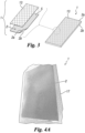
- An example of a knitted structure and its detailing is illustrated in Figure 5 .
- the weaving step results in the structural and optical characteristics of the support.
- the weaving step is preferably performed using one or more numerically controlled looms; the unit of measurement adopted to control the entire process is the micron ( ⁇ m).
- the weaving step involves a weaving technique that is developed in three basic structures, also known as weaves: plain, twill or satin; in essence, the weaving technique may involve a warp and weft structure ( woven weave ) .
- a knitted weave may be provided.
- the choice of the type of weave (woven or knitted weave) can be a function of the yarn material 3.
- the fabric 2 resulting from the weaving step is characterised by the breathability of the support 1 being produced; this is due to the fact that the threads woven during weaving create more or less large openings (or empty spaces) between the threads themselves (see for example the details in figure 5 and the schematic diagram in figure 1 ). These openings or gaps are calibrated and controlled during weaving, thus determining unique and specific breathability values for each fabric that can be produced; the fabrics that can be produced differ in the number of threads per centimetre in warp and weft, their diameter and the type of weave.
- the density of fabric 2 thus produced is measured by the number of threads placed in warp and weft and the nominal diameter of the yarns used and of each aperture in the hole obtained, also known as the 'mesh opening'.
- the fabrics made or capable of being made by the process according to the invention comprise knitted openings having a characteristic size from 2000 microns to 15 microns, yarns from 1000 to 15 microns in diameter and nominal thicknesses from 100 to 1000 microns.
- the weaving step preferably results in a reel of fabric having a knitted structure; note how in figure 1 (top, centre) only a portion of fabric 2 having a woven structure (or, alternatively, may be knitted) is schematised and not the entire reel.
- the reel has two main surfaces (or faces) that are opposed to each other, i.e. an upper surface 2a and a lower surface 2b.
- This step involves cleaning or washing the reel of fabric obtained from weaving. Cleaning or washing takes place preferably in solvent washing machines 4. This cleaning or washing step serves to remove, from the surface and openings, any residual natural lubricant used in the looms to ensure the low-friction sliding of the threads with the metal parts of the machine used to make the fabric (e.g. comb).
- fabric 2 is dried and stabilised in one or more 4' dryers, resulting in an extremely clean and stable product.
- the cleaning or washing step determines the quality of the subsequent metalization, as any dust or residue of lubricant determines imperfections on the final product yield, creating defects such as burns and stains. It is therefore important to have a clean/washed and dried fabric before proceeding to the metalization coating step, which is described below.
- the metalization step is illustrated schematically in figure 1 by means of layer 5, which conceptually represents the metalization coating; metalization takes place by means of steam, as explained below.
- Metalization is preferably carried out continuously ( roll to roll ) using PVD ( Physical Vapor Deposition ) technology, which deposits a layer of metal (metalization coating) between 100 and 500 nanometres.
- PVD Physical Vapor Deposition
- the vaporised metal deposition can be performed on only one face 2a, 2b of the fabric 2 or on both faces 2a, 2b.
- the metals that can be used for the metalization step are aluminium, titanium, copper, chrome or a mixture/mix of these metals with gas to obtain different colours.
- the metalization can be carried out by means of the machine 6 shown in figure 2 , which is known per se.
- the machine 6 includes a rewinder roller 7 ( rewinder ) , an unwinder roller 8 ( unwinder ) , a cooling roller 9, a transmission measuring system 10, a pre-treatment station 11 arranged upstream of the unwinder roller 8.
- the machine 6 further comprises a metalizing station 12 equipped with a modular plasma source 12a, oxygen inlet nozzles 12b and an evaporator 12c with a wire feeder; feeding may be by means of ingots or cylinders of metal wire.
- This metalization step returns a reel of finished material with effects similar to real wire mesh: shine, sheen and reflections.
- the reflection effects of fabric 2 are also remarkable due to the use of white yarns. Note how white yarn reflects light and the amount of metal deposited (nanometres) does not shield the reflection of the underlying material, but rather accentuates the effect.
- the metalization step involves coating at least one main surface 2a, 2b or two main surfaces 2a, 2b of fabric weave 2 with a metalization coating.
- the colour possibilities resulting from the metalization of fabric 2 are limited and it is therefore not possible to obtain variations and shades other than metalization.
- the printing step takes place.
- the printing step is schematically illustrated in Figure 1 by means of a layer 13 that conceptually represents any print or graphic representation that can be printed on the metalized fabric 2.
- the printing step involves printing on at least one surface 2a, 2b of the fabric 2 that has been previously metalized. Printing expands and completes the colour range of the fabric 2 and support 1 substantially to innumerable (theoretically infinite) colour possibilities and allows for customised solutions, e.g. on request, which may include drawings/outlines/patterns.
- the printing step similarly to the metalization step, may be performed on a main surface 2a, 2b or on both main surfaces 2a, 2b of the fabric 2.
- the metalization step can only be envisaged on the surface or surfaces that remain visible in the subsequent use of the support 1.
- both main surfaces 2a, 2b e.g., front surface and back surface
- both surfaces 2a, 2b can be printed; think of a work, comprising support 1, intended to be displayed on a pedestal with a 360° view.
- the process, and thus the resulting support may thus comprise: the same colour on both main surfaces 2a, 2b (faces), one or more different colours for each main surface 2a, 2b (for each face), one or more colours only on one main surface 2a, 2b (only on one face), drawings/outlines/patterns and/or one or more colours on both main surfaces 2a, 2b (faces) or only on one main surface 2a, 2b (only on one face).
- the printing step is carried out in such a way that the knitted structure of the weave of the fabric 2 is visible, i.e. it does not cover the knitted structure of the fabric 2, so that this knitted structure is visible.
- This contributes to the optimisation of the optical characteristics of the support 1; as the weave of fabric 2 is visible, its knitted structure guarantees certain light reflection properties.
- the printing step is preferably carried out on fabrics with metalization coating 5 in aluminium; the Applicant has in fact verified that metalizing the fabric with aluminium guarantees the best colour output of the printing step and thus of the resulting support. It is understood that it is however also possible to print on other metals, such as those indicated above.
- the printing step may substantially be a customisation step of the previously metalized fabric 2 in order to obtain a customised support.
- the printing step may involve printing any graphic representation, for example a drawing and/or an outline and/or a pattern and/or work of art.
- the graphic representation may be realised by means of artificial intelligence.
- the graphic representation may or may not be selected at the request of the customer. It is noted that the graphic representation may be a work of art in itself.
- the process may comprise, preferably after the printing step and thus preferably after the metalization step, one or more further processing steps.
- the one or more processing steps may serve to customise the previously metalized fabric 2 and thus the resulting support 1 and/or to provide the fabric with certain characteristics. Examples of such steps are embroidery, laser cutting, flocking, glittering, embossing, pleating and embossing. Note how, in some embodiments, one or more of these processing steps may precede or follow the printing and/or metalization step; this may be for reasons of process optimisation.
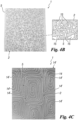
- Figure 4C shows a metalized fabric 2 on which an embroidery step involving the application of an embroidery 14 to the metalized fabric 2 was carried out.
- the embroidery pattern shown in Figure 4C is developed in accordance with a given pattern comprising a plurality of embroidery areas 14' each of which is provided with a "concentric" embroidery 14; it being understood that this example is in no way limiting and that the embroidery patterns 14, as well as the drawings/outlines/patterns realised with the other embroidery processes indicated above or with other further processes, are potentially infinite.
- Figure 4B shows a support 1 provided with apertures 15 which realise a pattern/outline; these apertures 15, as illustrated in detail on the right-hand side of figure 4B , are pass-through from the metalized and printed fabric 2.
- Such through openings 15 may be realised by a laser cutting step of the previously metalized support. The cutting step may therefore involve making the aforementioned patterns/outlines/drawings.
- the process preferably involves cutting the reel of material after the metalization and printing steps and any further processing steps, such as one or more of the previously mentioned steps.
- the finished product 1 (support) made by means of the process according to the invention, is not in a reel of material (although it is part of a reel before the aforementioned step of cutting the reel) but provides for cutting the fabric 2 after printing so as to obtain the desired dimensions for the support (and thus for the work of art), thus to obtain discrete pieces (supports 1).
- Figure 1 shows, bottom left, the reel of printed and metalized fabric 2 wherein the perimeter hatches (outer hatches, not the diagonal hatching) indicate possible cutting lines of the fabric 2 to make the support 1; such cutting lines can be made by scissors and/or by hand so as to make a pre-sizing of the support 1 to be cut.
- This cutting step is preferably carried out by laser cutting. Basically, by means of the laser, the dimensions of the support/finished work are defined; this laser cutting step can be carried out concurrently with the laser cutting step described above and aimed at realising the through openings 15.
- the process may comprise a layering step whereby one or more layers (foil or film) are applied to the metalized and printed fabric 2, in particular one layer at each major surface.
- Each layer used during the layering step is preferably made of plastic or vitreous material.
- the step of cutting the fabric 2 aimed at obtaining the desired dimensions for the support 1 is preferably carried out before the layering step since, preferably, the layering step described herein takes place with the metalized fabric already in the desired dimensions. Where applicable, the layering step is preferably carried out by lamination.
- the process may also include a step of attaching a frame 16, in jargon called a passpartout, and/or a support element 17 to the metalized and printed fabric 2 (see the exploded view in Figure 4D ).
- the step of attaching or engaging to metalized fabric 2 a support element 17 may involve:
- the step of engaging the metalized and printed fabric 2 to the main surface of the support element 17 to which the double-sided adhesive 19 has been applied involves the double-sided adhesive 19 penetrating one or more openings or gaps in the metalized fabric 2, in such a way as to "encase” the metalized fabric 2; thus, the mutual engagement between the fabric 2 and the support element 17 is very firm.
- the double-sided adhesive 19 may be provided with certain characteristics, such as viscosity and/or density, which allow it to penetrate into the empty spaces (mesh openings) of the weave of the fabric 2.
- a specific double-sided adhesive capable of penetrating into the mesh openings of the fabric 2 has been selected.
- This double-sided adhesive is applied through the use of a laminating machine 20 with a heated cylinder, illustrated in figure 4G , which allows the double-sided adhesive layer 19 (starting from the reels of double-sided adhesive 19 in figure 4F ) to be spread homogeneously on the support element 17 and then to subsequently apply the fabric 2, previously processed and printed with the desired graphic representation, to the double-sided adhesive layer 19 glued on the support element 17.
- the support element 17 (or lamination support) is made of plastic material, in particular polymethyl methacrylate (PMMA); it can be of any colour.
- the Applicant has verified that, to date, the choice of polymethylmethacrylate or plexiglass has proved to be the most suitable solution for ensuring strength, durability, avoiding problems of different thermal expansion of the materials (fabric and support element), due for example to the heated cylinder of the laminating machine 20 and/or the heating suffered during the use of the support 1 due to radiation or other thermal phenomena, and resistance to moisture, which may be a factor to be considered in the use of the support 1.
- other materials for the support element 17 such as: metals, wood, composite, flexible and/or rigid materials.
- the most suitable material for the support element 17 should be chosen according to one or more of the above conditions.
- both the frame 16 and the support element 17 are preferably engaged on a respective main surface 2a, 2b of the metalized and printed fabric 2.
- the support element 17 may be engaged on the back surface 2b of the fabric 2 and the frame 16 may be engaged on the front surface 2a of the fabric 2 or may otherwise be disposed in proximity to said front surface 2a.
- the frame 16 has an inner cavity bordered by an inner perimeter border 16a; within the cavity may be defined the portion of the metalized fabric 2 on which the printing has been performed.
- the support element 17 may have a hook or similar coupling element suitable to allow engagement of the support 1 to a vertical surface, for example of a partition or a wall.
- one or more attachments 21, in particular chosen to be anchored to the support element 17, and/or one or more threaded elements 22 adapted to fit into a respective hole made, for example by laser cutting, at the support element 17 may be provided as attachment elements.
- the frame 16 may be formed by at least two section bars 23, each of which is provided with a cavity 24; the cavity 24 may be defined by a substantially "C"-shaped section bar of the section bar 23 (see Figure 4E ).
- the section bars 23 form the frame 16; in this regard, see Figures 8 and 10 .
- the process involves housing at least partially perimeter portions of the metalized and printed fabric 2 within respective cavities 24 of respective section bars 23; this step is preferably carried out after engaging the fabric 2 to the support element 17 by means of the double-sided adhesive 19.
- One section bar 23 may be provided on each side of the fabric 2 and/or the support element 17.
- the binding of the fabric 2 within the cavities 24 of the section bars 23 may be achieved by means of adhesive, which may be inserted within the cavity 24 of the section bar 23.
- the section bars 24 may have end portions 23' configured to fit or match or correspond with respective end portions 23' of the other section bars 23; see for example Figure 4E where the section bar 23 shown has an angled end portion 23', for example at 45°, configured to allow assembly with another section bar 23 having a corresponding angled end portion 23'.
- the section bars 23 may be made of aluminium (e.g. extruded aluminium) and the adhesive used for bonding the fabric 2 may be single component.
- the support element may be a rigid support layer 17 configured to provide rigidity to the support 1 and thus to the work of art.
- the support element 17 may have dimensions, for example a length and/or width, that are comparable or similar to or greater than corresponding dimensions (length/width) of the metalized and printed fabric 2.
- the frame 16, the support element 17 and the metalized and printed fabric 2 have substantially the same width and length.
- the invention further relates to a support 1, preferably made according to the process described above.
- the support 1 is preferably configured to display a work of art.
- the support 1 includes:
- the knitted structure of the fabric 2, which is metalized and printed, is at least partially visible.
- the weaving is carried out using one or more white yarns 3, so as to provide the optical characteristics of the fabric 2 described above.
- the support has one or more through-holes 15 with respect to fabric 2; as illustrated in the detail of Figure 4D , through-holes 15 can define a certain pattern.
- the invention further relates to a use of the previously described support 1.
- the use of the support 1 is for the purpose of displaying a work of art.
- the support 1 may be engaged or hung from a vertical surface 18, preferably from a vertical wall; for this purpose, a support element 17 may be provided, for example a support layer to be arranged posteriorly with respect to the fabric 2.
- a support element 17 may thus be at least partially interposed between the fabric 2 and the vertical surface 18.
- the support 1 of figure 6 is substantially a painting and is provided with a frame 16. Further paintings in accordance with the invention are illustrated in figures 7-10 .
- the support 1 can simply be placed against a vertical surface 18 (see figure 6 ) or be placed close to a vertical surface 18 or other surface.
- the process for making a support 1 that can be used for a work of art has been described above, the process according to the invention can also be used to make an element (component or part) of a design object.
- the object of design essentially performs the function of an ornament and/or embellishment.
- the invention also relates to an element (component) of a design object and its use.
- the use of the design object element is for the purpose of making or creating a design object.
- an object of design may be a lamp or a clock or other object.
- the printing step of printing on the knitted structure of the fabric 2 imparts a three-dimensional effect to the metalized fabric 2 and thus to the support 1 (consequently also to the work of art using said support 1).
- Such three-dimensional effect confers "depth" to the support 1 and/or provides an impression of movement to an observer of the support 1 and thus to the work of art itself; in this regard, see Figures 4B, 4C and 6 .
- the support 1 according to the invention exhibits quite peculiar characteristics and is unconventional.
- the support 1 in accordance with the invention is extremely lighter, thinner and more malleable; this is due to its fabric structure. Furthermore, the metalized surface of the support 1 according to the invention brings out the various weaves, which will then be the basis of the prints/works of art.
Landscapes
- Engineering & Computer Science (AREA)
- Textile Engineering (AREA)
- Laminated Bodies (AREA)
- Treatment Of Fiber Materials (AREA)
Abstract
- predisposing a fabric (2) provided with a woven or knitted structure,
- metalizing the fabric (2) at least on a main surface (2a, 2b) thereof, for example on a front surface (2a) and/or on a back surface (2b) thereof, said step providing to coat by a metalizing coating (5) the weave of the fabric (2) defining said at least one main surface (2a, 2b),
- printing on said at least one metalized surface (2a, 2b) of the fabric (2).
Description
- The present invention relates to a process for making a support or an element of a design object. The support is conceived to be used to display a work of art, while the element may be part of a design object (element for creating one or more design objects).
- The invention also relates to a support for a work of art or an element of a design object, a use of the support to display a work of art and a use of the element to make a design object.
- As understood in this context, an example of a support for a work of art is a painting.
- Supports for works of art, e.g. canvas or paper supports, are known.
- A support, commercially known as 'DIBOND', is known and it is formed by a rigid panel with a 'sandwich' structure, consisting of two 0.3 mm thick aluminium cover layers (outer layers, one above and one below) and a central polyethylene or mineral core.
- The Applicant noted that alternatives to such supports can be developed.
- The main purpose of the present invention is therefore to overcome the drawbacks previously described in connection with the prior art.
- It is therefore the purpose of the present invention to disclose a process for making a support, and a support thus made, that is technically reliable, ensuring solid structural characteristics and considerable optical characteristics.
- It is therefore a purpose of the invention to provide a support for a work of art or for a design object with remarkable optical characteristics (reflection, brightness, brilliance, three-dimensional effect), which enable the work of art to be displayed in an optimal manner and to enhance its characteristics.
- The invention also provides an alternative technical solution, of considerable effectiveness, to the solutions of the prior art. Moreover, the support alternative provided by the invention has optical characteristics that canvas or paper supports do not have and therefore constitutes an improvement.
- These and other purposes are achieved by a process for making a support, a support and a use of the support in accordance with the following description, the attached claims and the following aspects.
- Aspects of the invention, which form an integral part of the technical content of this patent text, are described herein. These aspects may be used to limit claims and/or define further claims during the life of this patent protection.
- Numbered aspects of the invention follow.
- 1. Process for making a product comprising the following steps:
- predispose a fabric with a weave, preferably having a woven structure (woven forming a 90° angle) or knitted structure (hereafter also simply 'knitted structure'),
- metalize the fabric on at least one of its main surfaces, e.g. on a front surface thereof and/or a back surface thereof, said metalization step being the coating of the fabric weave defining said at least one main surface,
- print on said at least one metalized surface of the fabric.
- 2. Aspect according to
aspect 1, where the product is a support for a work, particularly a work of art, or is an element of a design object. - 3. Aspect according to
aspect - 4. Aspect according to
aspect - 5. Aspect according to any of the preceding aspects, in which the printing step provides for the knitted structure of the fabric weave to be and/or remain at least partially visible.
Being visible, the knitted structure guarantees determined light reflection properties. - 6. Aspect according to any of the previous aspects, where the metalization step involves the use of at least one of the following metals, or a mixture thereof: aluminium, titanium, copper, chromium.
- 7. Aspect according to any of the previous aspects, in which the metalization step is carried out using PVD (Physical Vapor Deposition) technology.
- 8. Aspect according to any of the previous aspects, where the printing step involves printing a graphic representation on at least one metalized surface of the fabric.
- 9. Aspect according to any of the previous aspects, where the process also includes a cutting step, preferably laser cutting, of the fabric to achieve the desired product dimensions.
- 10. Aspect according to any of the preceding aspects, where the process also includes the step of cutting, preferably laser cutting, the metalized and printed fabric to the desired size.
- 11. Aspect according to
aspect - 12. Aspect according to any of the previous aspects, wherein:
- the step of predisposing a fabric with a weave comprises predisposing a fabric with a weave that is made from at least one yarn, optionally white colored yarn,
- the step of coating the weaving of the fabric defining said at least one main surface comprises coating said at least one yarn, optionally white colored yarn, with the metalization coating.
- 13. Aspect according to any of the previous aspects, in which the step of predisposing a fabric with a weave comprises the following steps:
- weaving a yarn, preferably weaving a mono-yarn, this step involves making a fabric with a knitted structure,
- optionally clean or wash the fabric, preferably with a knitted structure.
- 14. Aspect according to any of the previous aspects, in which the weaving step is carried out by means of one or more numerically controlled looms.
- 15. Aspect according to any of the previous aspects, in which the step of metalizing the fabric on at least one of its main surfaces takes place continuously.
- 16. Aspect according to any of the preceding aspects, in which the step of printing on said at least one metalized surface of the fabric takes place continuously.
- 17. Aspect according to any of the previous aspects, in which the step of printing on said at least one metalized surface is done by UV printing.
- 18. Aspect according to any of the previous aspects, where the process also includes a material removal step, e.g. removal of material using a laser.
- 19. Aspect according to any of the previous aspects, in which the material removal step is carried out after the printing step.
- 20. Aspect according to any of the previous aspects, in which the removal of material involves making one or more through openings in the fabric.
- 21. Aspect according to any of the previous aspects, in which the material removal step involves removing part of the fabric.
- 22. Aspect according to any of the above aspects, where the process also includes a step providing to embroider on the metalized and/or printed fabric.
- 23. Aspect according to any of the previous aspects, where said embroidery step being carried out before or after the printing step.
- 24. Aspect according to any of the above aspects, where the process additionally includes at least one of the following product processing steps: laser cutting, flocking, embossing, glittering, pleating and embossing.
- 25. Aspect according to
aspect 24, in which said at least one step of product processing is subsequent or prior to the printing step. - 26. Aspect according to
aspect 24 or 25, in which said at least one step of product processing is subsequent or prior to the printing step. - 27. Aspect according to any of the preceding aspects, wherein the process further comprises the step of engaging to the metalized fabric a support element, e.g. a support layer, configured to support the product and/or engage the product to a vertical surface.
- 28. Aspect according to any of the preceding aspects, where the process does not include the step of engaging a sheet of glass to the metalized product or placing the metalized product between sheets of glass.
- 29. Aspect according to any of the previous aspects, where the printing step is a digital printing step.
- 30. Aspect according to any of the previous aspects, where the process includes a layering step involving the application of one or more layers to the metalized and printed fabric, in particular one layer at each main surface.
- 31. Aspect according to aspect 30, in which each layer used during the layering step is preferably in plastic material.
- 32. Aspect according to aspect 30 or 31, in which each layer used during the layering step is a film or foil.
- 33. Aspect according to aspect 30 or 31 or 32, in which the layering step is achieved by lamination.
-
- 34. Product comprising:
- a fabric having a weave, preferably having a woven or knitted structure, the fabric being metalized on at least one of its main surfaces, e.g. on one of its front and/or back surfaces,
- a print made at least on said metalized surface.
- 35. Aspect according to any of the previous aspects, in which the metalized and printed knitted structure is at least partially visible.
- 36. Aspect according to any of the previous aspects, in which the product has one or more through openings with reference to the fabric.
- 37. Aspect according to any of the previous aspects, in which said one or more through openings define a determined pattern.
- 38. Aspect according to any one of aspects 34 to 37, wherein the product is made according to the process of any one of
aspects 1 to 33 and/or any one of the process claims. - 39. Aspect according to any of the previous aspects, in which the metalized surface is printed.
- 40. Aspect according to any of the above aspects, in which the fabric weave includes at least one white yarn.
- 41. Aspect according to any of the previous aspects, in which the weave is made from one or more white yarns.
- 42. Aspect according to any of the above aspects, in which the yarn is a polyester yarn or mono-yarn.
- 43. Aspect according to any of the preceding aspects, where the product is a support for a work, particularly for a work of art, or is an element of a design object.
-
- 44. Work, in particular a work of art, comprising:
- a support according to aspects 34 to 43 and/or any of the product claims and/or made according to the process of any of
aspects 1 to 33 and/or any of the process claims, - a support element configured to support and/or engage the support to a vertical surface.
- a support according to aspects 34 to 43 and/or any of the product claims and/or made according to the process of any of
- 45. Aspect according to aspect 44, wherein the work is made according to the process according to any one of
aspects 1 to 33 and/or any one of the process claims. USE - 46. Use of a product according to aspects 34 to 43 and/or any one of the product claims and/or made according to the process of any one of
aspects 1 to 33 and/or any one of the support or design object claims, as a support or as an element of a design object. - 47. Use of a support, in accordance with aspects 34 to 43 and/or any one of the support claims and/or made in accordance with the process of any one of
aspects 1 to 33 and/or any one of the process claims, for displaying a work, in particular a work of art. - 48. Aspect according to aspect 47, in which the support is engaged or hung on a vertical surface, preferably a vertical wall.
- 49. Use of an element of an object of design, according to aspects 34 to 43 and/or any of the claims of element of design object and/or made according to the process of any of
aspects 1 to 33 and/or any of the claims of process, to make an object of design. -
- 50. Aspect according to any of the preceding aspects, in which the support or element of a design object has a thickness of at least one or two orders of magnitude less than one of its dimensions defining its footprint, e.g. its width and/or length.
- 51. Aspect according to any of the above aspects, in which the printing made on the metalized fabric includes a graphic representation, optionally the graphic representation being realised by artificial intelligence.
- 52. Aspect according to any one of the preceding aspects, wherein the graphic representation comprises at least one of: a drawing and/or an outline and/or a pattern and/or a work of art, optionally the drawing and/or the outline and/or the pattern and/or the work of art being realised by artificial intelligence.
- 53. Aspect according to any of the above aspects, in which the support or element of the design object is, or corresponds to, the work of art itself.
- 54. Aspect according to any of the preceding aspects, in which the fabric has a metalization coating on at least one of its main surfaces, e.g. on one of its front and/or back surfaces.
- 55. Aspect according to any of the preceding aspects, in which the fabric is metalized on only one of its main surfaces, e.g. only on its front surface or on its back surface, or is metalized on both of its main surfaces, e.g. on both its front surface and its back surface.
- 56. Aspect according to any of the previous aspects, in which the metalization coating is between 80 and 600 nanometres thick, particularly between 100 and 500 nanometres.
- 57. Aspect according to any of the preceding aspects, in which the fabric comprises defined openings between threads defining the knitted structure having a characteristic size of 2000 microns to 15 microns.
- 58. Aspect according to any of the preceding aspects, in which the fabric comprises one or more yarns with diameter(s) between 1100 and 10 microns, in particular between 1000 and 15 microns.
- 59. Aspect according to any of the above aspects, in which the fabric is between 85 and 1200 microns thick.
- 60. Aspect according to any of the above aspects, in which the weaving is carried out exclusively by means of white yarn(s).
- 61. Aspect according to any of the preceding aspects of the process, in particular at least according to aspect 27, wherein the step of engaging a support element to the metalized fabric comprises the following steps:
- apply double-sided adhesive to a main surface, e.g. a front surface, of the support element,
- engaging the metalized and printed fabric to the main surface of the support element to which the double-sided adhesive has been applied.
- 62. Aspect according to aspect 61, in which the step of engaging the metalized and printed fabric to the main surface of the support element to which the double-sided adhesive has been applied involves the double-sided adhesive penetrating one or more openings or gaps in the metalized fabric.
- 63. Aspect according to any of the preceding aspects of process where the process includes applying a frame to the metalized and printed fabric.
- 64. Aspect according to aspect 63, in which the step of applying the frame includes:
- predisposing a plurality of section bars, each section bar having a cavity, the section bars being configured to form a frame,
- at least partially housing perimeter portions of the metalized and printed fabric within respective section bar cavities,
- preferably constraining, for example by means of adhesive, said respective perimeter portions of the metalized and printed fabric in said cavities.
- 65. Aspect according to aspects 63 or 64 and aspect 61 or 62, wherein the step of at least partially housing perimeter portions of the metalized and printed fabric within respective cavities of respective section bars is carried out after engaging the metalized fabric to the main surface of the support element to which the double-sided adhesive has been applied.
- 66. Aspect according to any of the preceding aspects and/or the appended claims, wherein the fabric does not comprise a yarn with several threads or fibres.
- 67. Aspect according to any of the preceding aspects and/or the attached claims, in which the fabric comprises a mono-yarn.
- Note that in the following detailed description corresponding parts/components/elements are indicated with the same numerical references. The figures may illustrate the subject matter of the invention by means of non-scaled representations; therefore, parts/components/elements illustrated in the accompanying figures and relating to the subject matter of the invention may relate only to schematic representations. The use of "/" herein means "and/or" unless expressly indicated otherwise.
- In the context of the present discussion, the use of terms such as "above", "superiorly", "over", "below", "inferiorly", "sideways", "laterally", "internal", "internally", "external", "externally", "horizontal", "horizontally", "vertical", "vertically", "frontal", "frontally", "rear", "rearwards", "right", "left", similar terms and variations thereof refer, unless otherwise specifically indicated, to at least one spatial orientation that the object of the invention may assume under conditions of use (see, for example, one or more of the appended figures).
- Unless otherwise specifically indicated, the terms "condition" or "configuration" may be used interchangeably in the context of this discussion. The expression "said at least one" is interchangeable with "each". The expression "each" and the like do not necessarily imply that there is more than one plurality of elements to which it refers; e.g. "each element" may refer to a single element or to a plurality of elements, depending on the context in which it is used and the embodiment to which it refers.
- In the context of the present discussion, one or more of the following definitions/conventions are applicable where appropriate and except where otherwise indicated and/or unless the context excludes it:
- "support for a work of art" means a support that is used to display a work of art or as an element for the creation of design objects; the work of art can be printed on the metalized fabric and the support can then incorporate the work of art itself,
- "Work of art" means a work of a creative character that can be impressed and/or displayed on a support,
- "element of an object of design" means a component or part of a design object;
- by "object of design" we mean an object that combines characteristics of functionality and aesthetics; in this regard, see the relevant Wikipedia page currently accessible at the following link: https://en.wikipedia.org/wiki/Design . By way of non-limiting example, it should be noted that such an object may be a lampshade for a designer lamp or a component of a clock or other. "Design" is to be understood as "ornamentation" and/or "embellishment". For example, preferably, by design object it is not meant an article of clothing,
- the support has a thickness that is less by at least one or two orders of magnitude than one of its dimensions that define its footprint in plan, e.g. a width thereof and/or a length thereof and/or a diagonal thereof,
- by "weave having a knitted structure' or specifically 'weave' it is meant a weave which may have a warp and weft structure (woven weave, such as plain weave, twill, satin) or a knitted structure or weave (knitted weave),
- "continuous printing" means "roll-to-roll printing",
- "continuous metalization" means "roll-to-roll metalization",
- the terms "thread" or "yarn" can be used interchangeably.
- The aforesaid conventions and definitions may be used, where necessary, to interpret the claims. If necessary, one or more of said conventions and definitions may be included in one or more of the following claims and/or in one or more of the preceding aspects, in particular when said claims and/or aspects use one or more expressions covered by one or more conventions or definitions.
- In order to better understand the invention and appreciate its advantages, some of its embodiments are described below, by way of example and not limitation, with reference to the attached figures, in which:
-
Figure 1 schematically illustrates a series of steps in the process of making a support according to an embodiment; in particular, in the upper part of the figure are shown, from left to right, the steps of preparing the yarn to be woven, the weaving step which realises a woven structure (or, alternatively, it may be a knitted weft) of the support, the finishing step and in the lower part of the figure are shown, from left to right, the metalization step which enables the coating of the support, the step of printing on the support and the step of cutting the printed fabric; -
Figure 2 illustrates a machine that allows the continuous metalization step (roll to roll) to be carried out to obtain the support according to the invention; -
Figure 3 illustrates the layered structure of the support in accordance with the invention, wherein the left side shows the exploded view of the knitted fabric layer (bottom layer) and the printing layer (top layer), while the right side shows the support after the printing step, wherein it can be seen that the printing only partially covers the fabric layer so as to exploit its optical properties of reflection, brilliance and/or transparency (such effects are particularly pronounced when the fabric is made from at least one white yarn); -
Figure 4A illustrates a photograph showing a support in accordance with the invention, made according to the process outlined inFigure 1 , engaged to a support layer which is arranged behind the metalized fabric; -
Figure 4B illustrates a photograph showing a support according to an embodiment of the invention, equipped with a certain pattern realised by laser removal of material; the detail inFigure 4B schematically shows the openings that realise this pattern, which are through the metalized and printed fabric; -
Figure 4C illustrates a photograph showing a support according to an embodiment of the invention; the support comprises an embroidery on the metalized and printed surface; -
Figure 4D illustrates an exploded view of a support according to an embodiment of the invention involving, from bottom to top: a support element, a metalized fabric and a frame; -
Figure 4E illustrates an exploded view of a support according to an embodiment of the invention. The exploded view shows: a support element, a section bar, an attachment and threaded element, metalized, printed and machined fabric and a double-sided adhesive layer schematically arranged under a raised edge of the fabric; -
Figure 4F illustrates double-sided adhesive reels; -
Figure 4G illustrates a laminating machine with a heated cylinder that can be used to apply the double-sided adhesive offigure 4F to the support element shown infigure 4E ; -
Figure 5 illustrates a photograph showing a metalized fabric, the detail of which schematically shows a possible woven structure (or, alternatively, it may be a knitted structure) of the weave; -
Figure 6 illustrates a use of the support according to an embodiment of the invention involving the display of a work of art in an indoor environment; -
Figure 7 illustrates an exploded view of a work of art using the support according to the invention; -
Figure 8 illustrates the work of art inFigure 7 in an assembled condition, in which schematically one edge of the printed fabric is raised to show the support element; -
Figure 9 illustrates an exploded view of another work of art using the support according to the invention, in which schematically an edge of the printed fabric is raised to show the support element to which double-sided adhesive is applied; -
Figure 10 illustrates a further work of art, in an assembled condition, using the support according to the invention. - The present invention relates to a process for making a support. As mentioned, the support is conceived to be used for displaying a work of art. The support, made by means of said process and also according to the invention, is indicated as a whole in the figures with
numerical reference 1. - The process comprises the following steps:
- predisposing a
fabric 2 with a weave having woven structure (where warp and weft form a 90° angle) or knitted structure (hereinafter also referred to simply as "knitted structure", both options of structure or weave being understood, unless otherwise indicated), - metalizing the
fabric 2 on at least one of its main surfaces, e.g. on itsfront surface 2a and/or itsback surface 2b, - printing at least on the metalized surface of the
fabric 2. - The step of predisposing a
fabric 2 with a knitted structure is carried out as follows. - A
yarn 3 is first prepared for weaving. Preferably, theyarn 3 is a mono-yarn, preferably made of polyester (PET) or polypropylene (PP) or nylon or polyvinylidene fluoride (PVDF) or polyamide (PA) or other material, which can be chosen according to its characteristics. Mono-yarn is preferably used as it guarantees an optimal yield on the finished product as it reflects light in a different and preferable way and guarantees a greater sheen compared to yarns with several threads. Among the above materials, polyester mono-yarn 3 is preferably used as it has high tenacity and low elongation; it also has excellent heat resistance and low reactivity with chemicals. Theyarn 3 used may be white in colour, which guarantees brightness and transparency. Preferably, weaving is carried out using only white-coloured yarn 3. Alternatively, theyarn 3 may be in a single alternative colour to white. Theyarn 3, during the extrusion process (extrusion is part of the yarn manufacturing process, which takes place upstream of theyarn preparation step 3 of the process according to the invention), is checked for regularity in diameter and for ovality and different tensions in the polyester structure. The control of theyarn 3 at the step of its production makes it possible to avoid defects before starting to produce thesupport 1; in fact, after having prepared theyarn 3, possible irregularities of the yarns can then only be detected after the metalization step and thus irreversibly damage the final product (the support) 1 and its aesthetic performance. - After the
yarn 3 has been prepared for weaving, the weaving step takes place. The weaving step allows the creation of thefabric 2 having a knitted structure, which essentially constitutes the basis of thesupport 1, since the subsequent steps of the process described herein are developed on it. An example of a knitted structure and its detailing is illustrated inFigure 5 . Basically, the weaving step results in the structural and optical characteristics of the support. The weaving step is preferably performed using one or more numerically controlled looms; the unit of measurement adopted to control the entire process is the micron (µm). The weaving step involves a weaving technique that is developed in three basic structures, also known as weaves: plain, twill or satin; in essence, the weaving technique may involve a warp and weft structure (woven weave). As an alternative to the warp and weft structure (woven weave), a knitted weave may be provided. The choice of the type of weave (woven or knitted weave) can be a function of theyarn material 3. - The
fabric 2 resulting from the weaving step is characterised by the breathability of thesupport 1 being produced; this is due to the fact that the threads woven during weaving create more or less large openings (or empty spaces) between the threads themselves (see for example the details infigure 5 and the schematic diagram infigure 1 ). These openings or gaps are calibrated and controlled during weaving, thus determining unique and specific breathability values for each fabric that can be produced; the fabrics that can be produced differ in the number of threads per centimetre in warp and weft, their diameter and the type of weave. The density offabric 2 thus produced is measured by the number of threads placed in warp and weft and the nominal diameter of the yarns used and of each aperture in the hole obtained, also known as the 'mesh opening'. The number of threads is related to the centimetre and the diameter of the thread and opening is preferably specified in microns. The number of threads per centimetre and the diameter of the threads are mutually related; in fact, normally, increasing the number of threads decreases their diameter. The aperture (or empty space) of the mesh is expressed as the space between two parallel and adjacent threads, or as the percentage of free surface (ratio of the area occupied by the threads to the open area). The percentage of free area and the linear measure of the mesh opening are thus directly influenced by the number and diameter of the threads. Preferably, the fabrics made or capable of being made by the process according to the invention comprise knitted openings having a characteristic size from 2000 microns to 15 microns, yarns from 1000 to 15 microns in diameter and nominal thicknesses from 100 to 1000 microns. - The weaving step preferably results in a reel of fabric having a knitted structure; note how in
figure 1 (top, centre) only a portion offabric 2 having a woven structure (or, alternatively, may be knitted) is schematised and not the entire reel. The reel has two main surfaces (or faces) that are opposed to each other, i.e. anupper surface 2a and alower surface 2b. - After weaving, the fabric is finished 2. This step involves cleaning or washing the reel of fabric obtained from weaving. Cleaning or washing takes place preferably in
solvent washing machines 4. This cleaning or washing step serves to remove, from the surface and openings, any residual natural lubricant used in the looms to ensure the low-friction sliding of the threads with the metal parts of the machine used to make the fabric (e.g. comb). At the end of the cleaning or washing step,fabric 2 is dried and stabilised in one or more 4' dryers, resulting in an extremely clean and stable product. The cleaning or washing step determines the quality of the subsequent metalization, as any dust or residue of lubricant determines imperfections on the final product yield, creating defects such as burns and stains. It is therefore important to have a clean/washed and dried fabric before proceeding to the metalization coating step, which is described below. - After the yarn construction and weaving steps, the fabric reel is ready for the metalization step. The metalization step is illustrated schematically in
figure 1 by means oflayer 5, which conceptually represents the metalization coating; metalization takes place by means of steam, as explained below. Metalization is preferably carried out continuously (roll to roll) using PVD (Physical Vapor Deposition) technology, which deposits a layer of metal (metalization coating) between 100 and 500 nanometres. The vaporised metal deposition can be performed on only oneface fabric 2 or on bothfaces - The metals that can be used for the metalization step are aluminium, titanium, copper, chrome or a mixture/mix of these metals with gas to obtain different colours.
- The metalization can be carried out by means of the
machine 6 shown infigure 2 , which is known per se. Themachine 6 includes a rewinder roller 7 (rewinder), an unwinder roller 8 (unwinder), a coolingroller 9, atransmission measuring system 10, apre-treatment station 11 arranged upstream of theunwinder roller 8. Themachine 6 further comprises ametalizing station 12 equipped with amodular plasma source 12a,oxygen inlet nozzles 12b and an evaporator 12c with a wire feeder; feeding may be by means of ingots or cylinders of metal wire. - This metalization step returns a reel of finished material with effects similar to real wire mesh: shine, sheen and reflections. The reflection effects of
fabric 2 are also remarkable due to the use of white yarns. Note how white yarn reflects light and the amount of metal deposited (nanometres) does not shield the reflection of the underlying material, but rather accentuates the effect. - To summarise, the metalization step involves coating at least one
main surface main surfaces fabric weave 2 with a metalization coating. The colour possibilities resulting from the metalization offabric 2 are limited and it is therefore not possible to obtain variations and shades other than metalization. - After the metalization step, the printing step takes place. The printing step is schematically illustrated in
Figure 1 by means of alayer 13 that conceptually represents any print or graphic representation that can be printed on the metalizedfabric 2. The printing step involves printing on at least onesurface fabric 2 that has been previously metalized. Printing expands and completes the colour range of thefabric 2 andsupport 1 substantially to innumerable (theoretically infinite) colour possibilities and allows for customised solutions, e.g. on request, which may include drawings/outlines/patterns. - The printing step, similarly to the metalization step, may be performed on a
main surface main surfaces fabric 2. In essence, the metalization step can only be envisaged on the surface or surfaces that remain visible in the subsequent use of thesupport 1. Thus, in the case of supports in which bothmain surfaces surfaces support 1, intended to be displayed on a pedestal with a 360° view. The process, and thus the resulting support, may thus comprise: the same colour on bothmain surfaces main surface main surface main surfaces main surface - As illustrated in the accompanying figures (see in particular
Figures 3, 4A ,4B and 4C ), the printing step is carried out in such a way that the knitted structure of the weave of thefabric 2 is visible, i.e. it does not cover the knitted structure of thefabric 2, so that this knitted structure is visible. This contributes to the optimisation of the optical characteristics of thesupport 1; as the weave offabric 2 is visible, its knitted structure guarantees certain light reflection properties. - The printing step takes place continuously (roll-to-roll) via a printing press with UV technology and synthetic inks. This technology guarantees UV colour resistance and broad compatibility with the plastics used in the eventual layering step, which is described below.
- The printing step is preferably carried out on fabrics with
metalization coating 5 in aluminium; the Applicant has in fact verified that metalizing the fabric with aluminium guarantees the best colour output of the printing step and thus of the resulting support. It is understood that it is however also possible to print on other metals, such as those indicated above. - The printing step may substantially be a customisation step of the previously metalized
fabric 2 in order to obtain a customised support. The printing step may involve printing any graphic representation, for example a drawing and/or an outline and/or a pattern and/or work of art. The graphic representation may be realised by means of artificial intelligence. By way of illustration but not limitation, it is noted that the graphic representation may or may not be selected at the request of the customer. It is noted that the graphic representation may be a work of art in itself. - The process may comprise, preferably after the printing step and thus preferably after the metalization step, one or more further processing steps. The one or more processing steps may serve to customise the previously metalized
fabric 2 and thus the resultingsupport 1 and/or to provide the fabric with certain characteristics. Examples of such steps are embroidery, laser cutting, flocking, glittering, embossing, pleating and embossing. Note how, in some embodiments, one or more of these processing steps may precede or follow the printing and/or metalization step; this may be for reasons of process optimisation. -
Figure 4C shows ametalized fabric 2 on which an embroidery step involving the application of anembroidery 14 to the metalizedfabric 2 was carried out. The embroidery pattern shown inFigure 4C is developed in accordance with a given pattern comprising a plurality of embroidery areas 14' each of which is provided with a "concentric"embroidery 14; it being understood that this example is in no way limiting and that theembroidery patterns 14, as well as the drawings/outlines/patterns realised with the other embroidery processes indicated above or with other further processes, are potentially infinite. -
Figure 4B shows asupport 1 provided withapertures 15 which realise a pattern/outline; theseapertures 15, as illustrated in detail on the right-hand side offigure 4B , are pass-through from the metalized and printedfabric 2. Such throughopenings 15 may be realised by a laser cutting step of the previously metalized support. The cutting step may therefore involve making the aforementioned patterns/outlines/drawings. - The process preferably involves cutting the reel of material after the metalization and printing steps and any further processing steps, such as one or more of the previously mentioned steps. Thus, the finished product 1 (support), made by means of the process according to the invention, is not in a reel of material (although it is part of a reel before the aforementioned step of cutting the reel) but provides for cutting the
fabric 2 after printing so as to obtain the desired dimensions for the support (and thus for the work of art), thus to obtain discrete pieces (supports 1).Figure 1 shows, bottom left, the reel of printed andmetalized fabric 2 wherein the perimeter hatches (outer hatches, not the diagonal hatching) indicate possible cutting lines of thefabric 2 to make thesupport 1; such cutting lines can be made by scissors and/or by hand so as to make a pre-sizing of thesupport 1 to be cut. This cutting step is preferably carried out by laser cutting. Basically, by means of the laser, the dimensions of the support/finished work are defined; this laser cutting step can be carried out concurrently with the laser cutting step described above and aimed at realising the throughopenings 15. - The process may comprise a layering step whereby one or more layers (foil or film) are applied to the metalized and printed
fabric 2, in particular one layer at each major surface. Each layer used during the layering step is preferably made of plastic or vitreous material. The step of cutting thefabric 2 aimed at obtaining the desired dimensions for thesupport 1 is preferably carried out before the layering step since, preferably, the layering step described herein takes place with the metalized fabric already in the desired dimensions. Where applicable, the layering step is preferably carried out by lamination. - The process may also include a step of attaching a
frame 16, in jargon called a passepartout, and/or asupport element 17 to the metalized and printed fabric 2 (see the exploded view inFigure 4D ). - The step of attaching or engaging to metalized
fabric 2 asupport element 17 may involve: - applying double-sided adhesive 19 (e.g. thick double-sided adhesive) to a main surface, e.g. a front surface, of the
support element 17, - engaging the metalized and printed
fabric 2 to the main surface of thesupport element 17 to which the double-sided adhesive 19 was applied. - The step of engaging the metalized and printed
fabric 2 to the main surface of thesupport element 17 to which the double-sided adhesive 19 has been applied involves the double-sided adhesive 19 penetrating one or more openings or gaps in the metalizedfabric 2, in such a way as to "encase" the metalizedfabric 2; thus, the mutual engagement between thefabric 2 and thesupport element 17 is very firm. For this purpose, the double-sided adhesive 19 may be provided with certain characteristics, such as viscosity and/or density, which allow it to penetrate into the empty spaces (mesh openings) of the weave of thefabric 2. In fact, in more detail, a specific double-sided adhesive capable of penetrating into the mesh openings of thefabric 2 has been selected. This double-sided adhesive is applied through the use of a laminatingmachine 20 with a heated cylinder, illustrated infigure 4G , which allows the double-sided adhesive layer 19 (starting from the reels of double-sided adhesive 19 infigure 4F ) to be spread homogeneously on thesupport element 17 and then to subsequently apply thefabric 2, previously processed and printed with the desired graphic representation, to the double-sided adhesive layer 19 glued on thesupport element 17. Preferably, the support element 17 (or lamination support) is made of plastic material, in particular polymethyl methacrylate (PMMA); it can be of any colour. The Applicant has verified that, to date, the choice of polymethylmethacrylate or plexiglass has proved to be the most suitable solution for ensuring strength, durability, avoiding problems of different thermal expansion of the materials (fabric and support element), due for example to the heated cylinder of the laminatingmachine 20 and/or the heating suffered during the use of thesupport 1 due to radiation or other thermal phenomena, and resistance to moisture, which may be a factor to be considered in the use of thesupport 1. Notwithstanding, there are no limitations to using other materials for thesupport element 17, such as: metals, wood, composite, flexible and/or rigid materials. Preferably, the most suitable material for thesupport element 17 should be chosen according to one or more of the above conditions. - If both the
frame 16 and thesupport element 17 are provided, they are preferably engaged on a respectivemain surface fabric 2. As illustrated inFigure 4D , thesupport element 17 may be engaged on theback surface 2b of thefabric 2 and theframe 16 may be engaged on thefront surface 2a of thefabric 2 or may otherwise be disposed in proximity to saidfront surface 2a. Theframe 16 has an inner cavity bordered by aninner perimeter border 16a; within the cavity may be defined the portion of the metalizedfabric 2 on which the printing has been performed. Thesupport element 17 may have a hook or similar coupling element suitable to allow engagement of thesupport 1 to a vertical surface, for example of a partition or a wall. In an embodiment, illustrated inFigure 4E , one ormore attachments 21, in particular chosen to be anchored to thesupport element 17, and/or one or more threadedelements 22 adapted to fit into a respective hole made, for example by laser cutting, at thesupport element 17 may be provided as attachment elements. - The
frame 16 may be formed by at least two section bars 23, each of which is provided with acavity 24; thecavity 24 may be defined by a substantially "C"-shaped section bar of the section bar 23 (seeFigure 4E ). In the assembled condition, the section bars 23 form theframe 16; in this regard, seeFigures 8 and 10 . The process involves housing at least partially perimeter portions of the metalized and printedfabric 2 withinrespective cavities 24 of respective section bars 23; this step is preferably carried out after engaging thefabric 2 to thesupport element 17 by means of the double-sided adhesive 19. Onesection bar 23 may be provided on each side of thefabric 2 and/or thesupport element 17. The binding of thefabric 2 within thecavities 24 of the section bars 23 may be achieved by means of adhesive, which may be inserted within thecavity 24 of thesection bar 23. The section bars 24 may have end portions 23' configured to fit or match or correspond with respective end portions 23' of the other section bars 23; see for exampleFigure 4E where thesection bar 23 shown has an angled end portion 23', for example at 45°, configured to allow assembly with anothersection bar 23 having a corresponding angled end portion 23'. In a preferred embodiment, the section bars 23 may be made of aluminium (e.g. extruded aluminium) and the adhesive used for bonding thefabric 2 may be single component. - As illustrated in
Figure 4D , the support element may be arigid support layer 17 configured to provide rigidity to thesupport 1 and thus to the work of art. Thesupport element 17 may have dimensions, for example a length and/or width, that are comparable or similar to or greater than corresponding dimensions (length/width) of the metalized and printedfabric 2. In the example ofFigure 4D , theframe 16, thesupport element 17 and the metalized and printedfabric 2 have substantially the same width and length. - The invention further relates to a
support 1, preferably made according to the process described above. Thesupport 1 is preferably configured to display a work of art. - The
support 1 includes: - a
fabric 2 having a knitted weave and metalized on at least one of itsmain surfaces front surface 2a thereof and/or on oneback surface 2b thereof, - a
print 13 made at least on the above-mentionedmetalized surface - As illustrated in the attached figures, the knitted structure of the
fabric 2, which is metalized and printed, is at least partially visible. Preferably, the weaving is carried out using one or morewhite yarns 3, so as to provide the optical characteristics of thefabric 2 described above. - As previously mentioned, the support has one or more through-
holes 15 with respect tofabric 2; as illustrated in the detail ofFigure 4D , through-holes 15 can define a certain pattern. - The invention further relates to a use of the previously described
support 1. The use of thesupport 1 is for the purpose of displaying a work of art. - In use, the
support 1 may be engaged or hung from avertical surface 18, preferably from a vertical wall; for this purpose, asupport element 17 may be provided, for example a support layer to be arranged posteriorly with respect to thefabric 2. In use, as illustrated infigure 6 , such asupport element 17 may thus be at least partially interposed between thefabric 2 and thevertical surface 18. By way of example only and not limitation, it should be noted that thesupport 1 offigure 6 is substantially a painting and is provided with aframe 16. Further paintings in accordance with the invention are illustrated infigures 7-10 . - As an alternative to the
support element 17, thesupport 1 can simply be placed against a vertical surface 18 (seefigure 6 ) or be placed close to avertical surface 18 or other surface. - Although the process for making a
support 1 that can be used for a work of art has been described above, the process according to the invention can also be used to make an element (component or part) of a design object. The object of design essentially performs the function of an ornament and/or embellishment. - Thus, the invention also relates to an element (component) of a design object and its use. The use of the design object element is for the purpose of making or creating a design object. By way of example and not limitation, it is noted that an object of design may be a lamp or a clock or other object.
- The printing step of printing on the knitted structure of the
fabric 2 imparts a three-dimensional effect to the metalizedfabric 2 and thus to the support 1 (consequently also to the work of art using said support 1). Such three-dimensional effect confers "depth" to thesupport 1 and/or provides an impression of movement to an observer of thesupport 1 and thus to the work of art itself; in this regard, seeFigures 4B, 4C and6 . Thus, thesupport 1 according to the invention exhibits quite peculiar characteristics and is unconventional. - Compared to some prior art supports, for example DIBOND, the
support 1 in accordance with the invention is extremely lighter, thinner and more malleable; this is due to its fabric structure. Furthermore, the metalized surface of thesupport 1 according to the invention brings out the various weaves, which will then be the basis of the prints/works of art. - The protection conferred by the claims extends to each element, component and/or step of the invention equivalent to the one(s) claimed.
- It is understood that each element, component and/or step of the product/process according to the invention may be replaced with an equivalent element, component and/or step (hereinafter, "equivalent(s)"); such equivalent(s) may already exist on the filing or priority date of this patent text or subsequent conception/development.
Claims (16)
- Process of making a support (1) for a work-of-art or an element of an object of design, comprising the following steps:- predisposing a fabric (2) provided with a weave having a woven or knitted structure,- metalizing the fabric (2) at least on a main surface (2a, 2b) thereof, for example on a front surface (2a) thereof and/or on a back surface (2b) thereof, said step providing to coat by a metalizing coating (5) the weave of the fabric (2) defining said at least one main surface (2a, 2b),- printing on said at least one metalized surface (2a, 2b) of the fabric (2), wherein the printing step is performed so that the woven or knitted structure of the weave of the fabric (2) is partially exposed.
- Process according to claim 1, further comprising the step of cutting, preferably laser cutting, the fabric (2) for obtaining the desired dimensions of the support (1) or of the element of an object of design,
the step of cutting the fabric (2) being performed after the printing step. - Process according to claim 1 or 2, wherein:- the step of predisposing the fabric (2) provided with a weave comprises predisposing a fabric (2) provided with a weave which is made by at least one yarn (3), optionally by at least one white colored yarn (3),- the step of coating by a metallization coating (5) the weave of the fabric (2) defining said at least one main surface comprises coating said at least one yarn (3), optionally said at least one white colored yarn (3), by the metallization coating (5).
- Process according to claim 1 or 2 or 3, wherein the step of predisposing a fabric (2) provided with a weave comprises the step of weaving a mono-yarn (3).
- Process according to anyone of the preceding claims, wherein the step of metalizing the fabric (2) at least on a main surface (2a, 2b) thereof continuously occurs and/or wherein the step of printing on said at least one metalized surface (2a, 2b) of the fabric (2) continuously occurs.
- Process according to anyone of the preceding claims, wherein the step of printing on said at least one metalized surface (2a, 2b) occurs by printing using UV technology.
- Process according to anyone of the preceding claims, wherein the process further comprises a step of removing material, for example removing material by laser,
such step being performed after the printing step and providing to make one or more through openings (15) in the fabric (2). - Process according to anyone of the preceding claims, wherein the process further comprises a step providing to embroider on the metalized fabric (2),said embroidering step being performed after the printing stepand/or the process further comprises at least one of the following steps of processing the support (1) or the element of an object of design: laser cutting, flocking, embossing, glittering, pleating and embossing,preferably said at least one step of processing the support (1) or the object of design being performed after or before the printing step and/or before or after the metallization step.
- Process according to anyone of the preceding claims, wherein the process further comprises the step of engaging a support element (17) with the metalized fabric (2), for example a support layer, configured to sustain the support (1) and/or engage the support (1) to a vertical surface (18).
- Process according to claim 9, wherein the step of engaging a support element (17) with the metalized fabric (2) comprised the steps of:- applying double-sided adhesive (19) to a main surface, e.g. a front surface, of the support element (17),- engaging the metalized and printed fabric (2) to the main surface of the support element (17) to which the double-sided adhesive (19) has been applied.
- Process according to claim 10, wherein the step of engaging the metalized and printed fabric (2) to the main surface of the support element (17) to which the double-sided adhesive has been applied involves the double-sided adhesive (19) penetrating one or more openings or gaps in the metalized fabric (2).
- Process according to any of the preceding claims, comprising applying a frame (16) to the metalized and printed fabric (2), said step comprising:- predisposing a plurality of section bars (23), each section bar (23) being provided with a cavity (24), the section bars (23) being configured to form a frame (16),- at least partially housing perimeter portions of the metalized and printed fabric (2) within respective cavities (24) of respective section bars (23),- preferably, constraining, for example by means of adhesive, said respective perimeter portions of the metalized and printed fabric (2) in said cavities (24).
- Support (1) for a work-of-art or element of an object of design comprising:- a fabric (2) provided with a weave having a woven or knitted structure, the fabric (2) being metalized at least on one main surface (2a, 2b) thereof, for example on a front surface (2a) thereof and/or on a back surface (2b) thereof,- a print (13) made at least on said metalized surface (2a, 2b),
the metalized and printed woven or knitted structure being at least exposed, optionally the support (1) or the element of an object of design being made according to the process according to anyone of claims from 1 to 11. - Support or element of an object of design according to claim 13, wherein the weave of the fabric (2) comprises at least one white colored yarn (3).
- Support or element of an object of design according to claim 13 or 14, wherein the support or the element of an object of design exhibits one or more through openings (15) with reference to the fabric (2),
preferably said one or more through openings (15) defining a determined pattern. - Use of:- a support (1), according to claim 13 or 14 or 15 and/or made according to the process of claims from 1 to 12, for displaying a work-of-art, the support (1) being engaged or hung to a vertical surface (18), preferably to a vertical wall, or- an element of an object of design, according to claim 13 or 14 or 15 and/or made according to the process of claims from 1 to 12, for making an object of design.
Applications Claiming Priority (1)
| Application Number | Priority Date | Filing Date | Title |
|---|---|---|---|
| IT102023000017157A IT202300017157A1 (en) | 2023-08-10 | 2023-08-10 | PROCEDURE FOR MAKING A SUPPORT AND RELATED SUPPORT |
Publications (1)
| Publication Number | Publication Date |
|---|---|
| EP4520866A1 true EP4520866A1 (en) | 2025-03-12 |
Family
ID=88505067
Family Applications (1)
| Application Number | Title | Priority Date | Filing Date |
|---|---|---|---|
| EP24191829.1A Pending EP4520866A1 (en) | 2023-08-10 | 2024-07-30 | Process of making a support and support thereof |
Country Status (2)
| Country | Link |
|---|---|
| EP (1) | EP4520866A1 (en) |
| IT (1) | IT202300017157A1 (en) |
Citations (2)
| Publication number | Priority date | Publication date | Assignee | Title |
|---|---|---|---|---|
| US2670554A (en) * | 1952-05-09 | 1954-03-02 | Francis Louis | Metalized art canvas |
| US20190017785A1 (en) * | 2011-10-11 | 2019-01-17 | Ametrine Technologies Ltd. | Multispectral Camouflage Material |
-
2023
- 2023-08-10 IT IT102023000017157A patent/IT202300017157A1/en unknown
-
2024
- 2024-07-30 EP EP24191829.1A patent/EP4520866A1/en active Pending
Patent Citations (2)
| Publication number | Priority date | Publication date | Assignee | Title |
|---|---|---|---|---|
| US2670554A (en) * | 1952-05-09 | 1954-03-02 | Francis Louis | Metalized art canvas |
| US20190017785A1 (en) * | 2011-10-11 | 2019-01-17 | Ametrine Technologies Ltd. | Multispectral Camouflage Material |
Also Published As
| Publication number | Publication date |
|---|---|
| IT202300017157A1 (en) | 2025-02-10 |
Similar Documents
| Publication | Publication Date | Title |
|---|---|---|
| US20100316832A1 (en) | Flocked article having a woven insert and method for making the same | |
| JPS60502060A (en) | Vertical blind slats and assemblies and their assembly parts | |
| DE69403390T2 (en) | wallpaper | |
| EP2031125A1 (en) | Manufacturing method of fabrics with colored stereoscopic patterns and fabrics manufactured therefrom | |
| HK1043396A1 (en) | Label and method for producing labels | |
| US20030198746A1 (en) | Nonwoven fabric having three-dimensional printed surface and method for producing the same | |
| EP3138944B1 (en) | Lace fabric and method of knitting lace fabric | |
| KR101678489B1 (en) | Multi-layered Chromogenic Fabric with Surface Glare Effect, and Method for Manufacturing the Same | |
| CN100430542C (en) | Method for manufacturing color double-face symmetrical pattern jacquard | |
| IT202300017157A1 (en) | PROCEDURE FOR MAKING A SUPPORT AND RELATED SUPPORT | |
| EP2507423B1 (en) | Method for producing carpets with fringes, fabrics and carpets produced according to this method | |
| KR101646345B1 (en) | Fabrics and method of manufacturing the same | |
| CN107557967B (en) | Production process of double-color warp and multi-color weft interwoven jacquard double-sided thread blanket | |
| US20050271862A1 (en) | Flame-retardant camouflage material for military applications | |
| CA2504071A1 (en) | Flame retardant camouflage material for military applications | |
| KR100948234B1 (en) | Manufacturing method of metallic yarn which have different color on both side and textiles which have irregular interval stripes and its weaving method | |
| CN201148500Y (en) | Multi-layer arbitrary layer exchanging fabric | |
| KR101786457B1 (en) | Engraved fabric having multiple layers and method of making that fabric | |
| US20030199220A1 (en) | Nonwoven fabric having three-dimensional printed surface and method for producing the same | |
| JP4888700B2 (en) | Scale-like knitted fabric | |
| US20120031149A1 (en) | Textile with leather threads | |
| CN219326887U (en) | Terylene jacquard multicolor fabric | |
| JP7429487B2 (en) | Textiles and methods of manufacturing them | |
| CN114232174B (en) | AB double-faced irregular pattern six-layer blanket fabric and weaving process thereof | |
| KR100749310B1 (en) | Fabric manufacturing method |
Legal Events
| Date | Code | Title | Description |
|---|---|---|---|
| PUAI | Public reference made under article 153(3) epc to a published international application that has entered the european phase |
Free format text: ORIGINAL CODE: 0009012 |
|
| STAA | Information on the status of an ep patent application or granted ep patent |
Free format text: STATUS: THE APPLICATION HAS BEEN PUBLISHED |
|
| AK | Designated contracting states |
Kind code of ref document: A1 Designated state(s): AL AT BE BG CH CY CZ DE DK EE ES FI FR GB GR HR HU IE IS IT LI LT LU LV MC ME MK MT NL NO PL PT RO RS SE SI SK SM TR |
|
| STAA | Information on the status of an ep patent application or granted ep patent |
Free format text: STATUS: REQUEST FOR EXAMINATION WAS MADE |
|
| P01 | Opt-out of the competence of the unified patent court (upc) registered |
Free format text: CASE NUMBER: UPC_APP_0062_4520866/2025 Effective date: 20250709 |
|
| 17P | Request for examination filed |
Effective date: 20250812 |