EP4520695A1 - Winding and unwinding system, control method, and preparation device for battery electrode sheet - Google Patents
Winding and unwinding system, control method, and preparation device for battery electrode sheet Download PDFInfo
- Publication number
- EP4520695A1 EP4520695A1 EP23864417.3A EP23864417A EP4520695A1 EP 4520695 A1 EP4520695 A1 EP 4520695A1 EP 23864417 A EP23864417 A EP 23864417A EP 4520695 A1 EP4520695 A1 EP 4520695A1
- Authority
- EP
- European Patent Office
- Prior art keywords
- winding
- roller
- roll
- strip material
- changing
- Prior art date
- Legal status (The legal status is an assumption and is not a legal conclusion. Google has not performed a legal analysis and makes no representation as to the accuracy of the status listed.)
- Pending
Links
Images

Classifications
-
- B—PERFORMING OPERATIONS; TRANSPORTING
- B65—CONVEYING; PACKING; STORING; HANDLING THIN OR FILAMENTARY MATERIAL
- B65H—HANDLING THIN OR FILAMENTARY MATERIAL, e.g. SHEETS, WEBS, CABLES
- B65H23/00—Registering, tensioning, smoothing or guiding webs
- B65H23/04—Registering, tensioning, smoothing or guiding webs longitudinally
- B65H23/18—Registering, tensioning, smoothing or guiding webs longitudinally by controlling or regulating the web-advancing mechanism, e.g. mechanism acting on the running web
- B65H23/1806—Registering, tensioning, smoothing or guiding webs longitudinally by controlling or regulating the web-advancing mechanism, e.g. mechanism acting on the running web in reel-to-reel type web winding and unwinding mechanism, e.g. mechanism acting on web-roll spindle
-
- B—PERFORMING OPERATIONS; TRANSPORTING
- B65—CONVEYING; PACKING; STORING; HANDLING THIN OR FILAMENTARY MATERIAL
- B65H—HANDLING THIN OR FILAMENTARY MATERIAL, e.g. SHEETS, WEBS, CABLES
- B65H19/00—Changing the web roll
- B65H19/22—Changing the web roll in winding mechanisms or in connection with winding operations
-
- B—PERFORMING OPERATIONS; TRANSPORTING
- B65—CONVEYING; PACKING; STORING; HANDLING THIN OR FILAMENTARY MATERIAL
- B65H—HANDLING THIN OR FILAMENTARY MATERIAL, e.g. SHEETS, WEBS, CABLES
- B65H19/00—Changing the web roll
- B65H19/22—Changing the web roll in winding mechanisms or in connection with winding operations
- B65H19/2207—Changing the web roll in winding mechanisms or in connection with winding operations the web roll being driven by a winding mechanism of the centre or core drive type
- B65H19/2215—Turret-type with two roll supports
-
- B—PERFORMING OPERATIONS; TRANSPORTING
- B65—CONVEYING; PACKING; STORING; HANDLING THIN OR FILAMENTARY MATERIAL
- B65H—HANDLING THIN OR FILAMENTARY MATERIAL, e.g. SHEETS, WEBS, CABLES
- B65H20/00—Advancing webs
- B65H20/02—Advancing webs by friction roller
-
- B—PERFORMING OPERATIONS; TRANSPORTING
- B65—CONVEYING; PACKING; STORING; HANDLING THIN OR FILAMENTARY MATERIAL
- B65H—HANDLING THIN OR FILAMENTARY MATERIAL, e.g. SHEETS, WEBS, CABLES
- B65H26/00—Warning or safety devices, e.g. automatic fault detectors, stop-motions, for web-advancing mechanisms
- B65H26/06—Warning or safety devices, e.g. automatic fault detectors, stop-motions, for web-advancing mechanisms responsive to predetermined lengths of webs
-
- B—PERFORMING OPERATIONS; TRANSPORTING
- B65—CONVEYING; PACKING; STORING; HANDLING THIN OR FILAMENTARY MATERIAL
- B65H—HANDLING THIN OR FILAMENTARY MATERIAL, e.g. SHEETS, WEBS, CABLES
- B65H26/00—Warning or safety devices, e.g. automatic fault detectors, stop-motions, for web-advancing mechanisms
- B65H26/08—Warning or safety devices, e.g. automatic fault detectors, stop-motions, for web-advancing mechanisms responsive to a predetermined diameter
-
- H—ELECTRICITY
- H01—ELECTRIC ELEMENTS
- H01M—PROCESSES OR MEANS, e.g. BATTERIES, FOR THE DIRECT CONVERSION OF CHEMICAL ENERGY INTO ELECTRICAL ENERGY
- H01M10/00—Secondary cells; Manufacture thereof
- H01M10/04—Construction or manufacture in general
- H01M10/0404—Machines for assembling batteries
- H01M10/0409—Machines for assembling batteries for cells with wound electrodes
-
- B—PERFORMING OPERATIONS; TRANSPORTING
- B65—CONVEYING; PACKING; STORING; HANDLING THIN OR FILAMENTARY MATERIAL
- B65H—HANDLING THIN OR FILAMENTARY MATERIAL, e.g. SHEETS, WEBS, CABLES
- B65H2301/00—Handling processes for sheets or webs
- B65H2301/40—Type of handling process
- B65H2301/41—Winding, unwinding
- B65H2301/414—Winding
-
- B—PERFORMING OPERATIONS; TRANSPORTING
- B65—CONVEYING; PACKING; STORING; HANDLING THIN OR FILAMENTARY MATERIAL
- B65H—HANDLING THIN OR FILAMENTARY MATERIAL, e.g. SHEETS, WEBS, CABLES
- B65H2511/00—Dimensions; Position; Numbers; Identification; Occurrences
- B65H2511/10—Size; Dimensions
- B65H2511/11—Length
-
- B—PERFORMING OPERATIONS; TRANSPORTING
- B65—CONVEYING; PACKING; STORING; HANDLING THIN OR FILAMENTARY MATERIAL
- B65H—HANDLING THIN OR FILAMENTARY MATERIAL, e.g. SHEETS, WEBS, CABLES
- B65H2511/00—Dimensions; Position; Numbers; Identification; Occurrences
- B65H2511/10—Size; Dimensions
- B65H2511/14—Diameter, e.g. of roll or package
-
- B—PERFORMING OPERATIONS; TRANSPORTING
- B65—CONVEYING; PACKING; STORING; HANDLING THIN OR FILAMENTARY MATERIAL
- B65H—HANDLING THIN OR FILAMENTARY MATERIAL, e.g. SHEETS, WEBS, CABLES
- B65H2553/00—Sensing or detecting means
- B65H2553/40—Sensing or detecting means using optical, e.g. photographic, elements
- B65H2553/41—Photoelectric detectors
- B65H2553/412—Photoelectric detectors in barrier arrangements, i.e. emitter facing a receptor element
-
- B—PERFORMING OPERATIONS; TRANSPORTING
- B65—CONVEYING; PACKING; STORING; HANDLING THIN OR FILAMENTARY MATERIAL
- B65H—HANDLING THIN OR FILAMENTARY MATERIAL, e.g. SHEETS, WEBS, CABLES
- B65H2553/00—Sensing or detecting means
- B65H2553/51—Encoders, e.g. linear
-
- B—PERFORMING OPERATIONS; TRANSPORTING
- B65—CONVEYING; PACKING; STORING; HANDLING THIN OR FILAMENTARY MATERIAL
- B65H—HANDLING THIN OR FILAMENTARY MATERIAL, e.g. SHEETS, WEBS, CABLES
- B65H2801/00—Application field
- B65H2801/72—Fuel cell manufacture
-
- Y—GENERAL TAGGING OF NEW TECHNOLOGICAL DEVELOPMENTS; GENERAL TAGGING OF CROSS-SECTIONAL TECHNOLOGIES SPANNING OVER SEVERAL SECTIONS OF THE IPC; TECHNICAL SUBJECTS COVERED BY FORMER USPC CROSS-REFERENCE ART COLLECTIONS [XRACs] AND DIGESTS
- Y02—TECHNOLOGIES OR APPLICATIONS FOR MITIGATION OR ADAPTATION AGAINST CLIMATE CHANGE
- Y02E—REDUCTION OF GREENHOUSE GAS [GHG] EMISSIONS, RELATED TO ENERGY GENERATION, TRANSMISSION OR DISTRIBUTION
- Y02E60/00—Enabling technologies; Technologies with a potential or indirect contribution to GHG emissions mitigation
- Y02E60/10—Energy storage using batteries
Definitions
- This application relates to the field of battery technologies, and in particular, to a winding and unwinding system, a control method, and a preparation device for a battery electrode sheet.
- an objective of this application is to provide a winding and unwinding system, a control method, and a preparation device for a battery electrode sheet to improve the measurement accuracy of the winding radius.
- Embodiments of a first aspect of this application provide a winding and unwinding system, including at least two winding rollers, a roll-changing device, a sensing device, a measuring device, and a controller.
- the roll-changing device is able to drive the at least two winding rollers to sequentially move to a set position, where a winding roller located at the set position is able to wind a strip material;
- the sensing device emits an in-place signal when the winding roller located at the set position rotates one circle; and the measuring device is configured to measure a traveling length of the strip material.
- the controller is connected to the sensing device, the measuring device, and the roll-changing device, where the controller, in response to receiving the in-place signal, determines a winding radius of the winding roller located at the set position based on the traveling length measured by the measuring device; and the controller sends a roll-changing signal to the roll-changing device when the winding radius reaches a preset threshold, where the roll-changing device, upon receiving the roll-changing signal, drives another winding roller to move to the set position and get in contact with the strip material, so that the strip material winds onto the another winding roller.
- the current circumference of the winding roller can be determined by measuring the traveling length of the strip material when the winding roller rotates one circle, and the current winding radius of the winding roller can be obtained accordingly.
- the method of measuring the winding radius in the winding and unwinding system of this embodiment is independent of thickness and tension of the strip material, and therefore is not affected by thickness of the electrode sheet and interlayer spacing of the electrode sheet, providing high measurement accuracy.
- the sensing device includes a light-emitting device and a receiving device, where the light-emitting device is configured to emit a photoelectric signal, and the receiving device is configured to receive the photoelectric signal, where when the winding roller located at the set position rotates one circle, a state of reception of the photoelectric signal by the receiving device changes and the receiving device emits the in-place signal.
- the sensing device is a photoelectric switch, which has the advantage of high detection accuracy.
- the light-emitting device and the receiving device are fixed and are disposed opposite each other, and the winding roller located at the set position is provided with a light-blocking member, where the light-blocking member is able to rotate with the winding roller to a position between the light-emitting device and the receiving device and block the photoelectric signal.
- the sensing device emits the in-place signal based on the rotation of the winding roller, cooperating with the controller for measurement.
- the sensing device is a slot-type photoelectric switch or a through-beam photoelectric switch.
- the slot-type sensing device provided as a slot-type photoelectric switch or a through-beam photoelectric switch is easy to obtain through purchase.
- the light-emitting device and the receiving device are integrated into a single component, eliminating the need for separate installations.
- the winding and unwinding system includes a traction mechanism, where the traction mechanism is located upstream of the winding roller in a conveying direction of the strip material to pull the strip material and convey it to the winding roller located at the set position.
- the traction mechanism can be configured to apply traction to the strip material to pull the strip material and convey it in a direction approaching the winding roller.
- the traction mechanism includes a traction motor, a driving traction roller, and a driven traction roller, where the driving traction roller is drivingly connected to the traction motor, and the strip material passes between the driving traction roller and the driven traction roller; and the measuring device determines the traveling length of the strip material by measuring a rotation angle or a rotation displacement of the driving traction roller or the driven traction roller.
- the measuring device is a meter wheel, and the meter wheel is in contact with a surface of the driving traction roller or the driven traction roller.
- the traveling length of the strip material can be directly determined, eliminating the need for conversion and resulting in a small amount of calculation.
- the meter wheel is not in contact with the strip material, avoiding affecting the strip material due to contact between the meter wheel and the active material layer on the strip material.
- a driving device and a roll-changing pressing roller drivingly connected to the driving device is further included, where the driving device is connected to the controller; where the controller sends a roll-pressing signal to the driving device when the winding radius reaches the preset threshold, and the driving device, upon receiving the roll-pressing signal, drives the roll-changing pressing roller to move close to the set position, so that the roll-changing pressing roller gets in contact with the strip material.
- the driving device includes an oscillating arm and a servo motor, where one end of the oscillating arm is connected to the roll-changing pressing roller, and another end of the oscillating arm is drivingly connected to the servo motor, the servo motor being connected to the controller.
- the winding and unwinding system further includes an unwinding roller, where the unwinding roller is configured to unwind the strip material, and the unwinding roller is located upstream of the winding roller in the conveying direction of the strip material.
- the winding and unwinding system of this embodiment Compared with the winding radius measuring performed by using the ultrasonic distance measuring sensor, the winding and unwinding system of this embodiment has higher measurement accuracy, which helps avoid errors in estimating the number of layers of the strip material wound on the unwinding roller due to measurement errors, thereby avoiding waste caused by the unwinding roller automatically changing rolls prematurely.
- Embodiments of a second aspect of this application provide a preparation device for a battery electrode sheet, which includes the winding and unwinding system provided in the embodiments of the first aspect of this application.
- Embodiments of a third aspect of this application provide a winding and unwinding control method applicable to the winding and unwinding system provided in the embodiments of the first aspect of this application.
- the control method includes: obtaining an in-place signal; determining, in response to receiving the in-place signal, a winding radius of the winding roller located at the set position based on the traveling length measured by the measuring device; and sending a roll-changing signal to the roll-changing device when the winding radius reaches a preset threshold to control the roll-changing device to drive another winding roller to move to the set position and get in contact with the strip material, so that the strip material winds onto the another winding roller.
- the control method further includes: sending a roll-pressing signal to the driving device when the winding radius reaches the preset threshold to control the driving device to drive the roll-changing pressing roller to move close to the set position, so that the roll-changing pressing roller gets in contact with the strip material.
- the term "and/or" is only an associative relationship for describing associated objects, indicating that three relationships may be present.
- a and/or B may indicate the following three cases: presence of only A, presence of both A and B, and presence of only B.
- the character "/" in this specification generally indicates an "or" relationship between contextually associated objects.
- a plurality of means more than two (inclusive).
- a plurality of groups means more than two (inclusive) groups
- a plurality of pieces means more than two (inclusive) pieces.
- mount should be understood in their general senses. For example, they may refer to a fixed connection, a detachable connection, or an integral connection, may refer to a mechanical connection or an electrical connection, and may refer to a direct connection, an indirect connection via an intermediate medium, an internal communication between two elements, or an interaction between two elements. Persons of ordinary skill in the art can understand specific meanings of these terms in this application as appropriate to specific situations.
- a battery mainly includes electrode assemblies.
- An electrode assembly which serves as a storage component, is mainly composed of a positive electrode sheet, a negative electrode sheet, and a separator. Operation of the battery mainly relies on migration of metal ions between the positive electrode sheet and the negative electrode sheet.
- Both the positive electrode sheet and the negative electrode sheet include a current collector and an active material layer, where the active material layer is applied on a surface of the current collector.
- the production process of the electrode sheets typically involves: using a coating device to apply an active material layer onto an electrode sheet. The electrode sheet coated with the active material layer is then conveyed to a roller pressing device, where the roller pressing device presses the electrode sheet to compact the current collector and the active material layer. After that, the electrode sheet is further conveyed to the winding roller for winding.
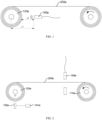
- FIG. 1 is a schematic diagram of a winding and unwinding system in a related example.
- an ultrasonic distance measuring sensor 180a may be used to directly detect the winding radius.
- the working principle of measuring the winding radius in this example is as follows: a distance between the ultrasonic distance measuring sensor 180a and the center of the winding roller 120a is a fixed value L1.
- the ultrasonic distance measuring sensor 180a can detect a distance L2 between itself and the winding roller 120a, so the winding radius is L1 - L2.
- the ultrasonic distance measuring sensor 180a to detect the winding radius: first, the cost of the ultrasonic distance measuring sensor 180a is high; second, a detection accuracy of the ultrasonic distance measuring sensor 180a is ⁇ 0.5 mm; however, thickness of the electrode sheet 200a is usually 4-6 micrometers ( ⁇ m).
- the theoretical number of layers of the electrode sheet 200a wound on the winding roller 120a calculated based on this is far greater than the actual number of layers of the electrode sheet 200a wound on the winding roller 120a, leading to an error in estimating the number of layers of the electrode sheet 200a wound on the winding roller 120a.
- a diameter of the winding roller 120a is equal to a diameter of the unwinding roller
- the number of layers of the electrode sheet 200a wound on the winding roller 120a is equal to the number of layers of the electrode sheet 200a unwound from the unwinding roller.
- the theoretical number of layers of the electrode sheet 200a unwound from the unwinding roller calculated is far greater than the actual number of layers of the electrode sheet 200a unwound from the unwinding roller, leading to an error in estimating the actual number of layers of the electrode sheet 200a unwound from the unwinding roller, and when causing the unwinding roller to automatically change rolls prematurely, this results in waste.
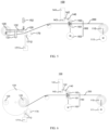
- FIG. 2 is a schematic diagram of another winding and unwinding system in a related example.
- the winding and unwinding system 100a includes an unwinding roller 110a, a winding roller 120a, a thickness measuring device 190a, a proximity switch 150a, and a counter 191a.
- the unwinding roller 110a is configured to unwind the electrode sheet 200a.
- the winding roller 120a is configured to wind the electrode sheet 200a.
- the thickness measuring device 190a is located downstream of the unwinding roller 110a and is configured to measure the thickness h of the electrode sheet 200a.
- the proximity switch 150a is configured to emit a signal to the counter 191a when the unwinding roller 110a winds one circle, and the counter 191a counts in response to receiving the signal.
- the working principle of measuring the winding radius in this example is as follows: each time the unwinding roller 110a rotates one circle, the unwinding radius decreases by 2h.
- the thickness of the electrode sheet 200a is uneven. Therefore, when this method is used to detect the winding radius, the thickness of the electrode sheet 200a affects the accuracy of the winding radius calculation.
- This winding and unwinding system uses a measuring device to measure the traveling length of the strip material when the winding roller rotates one circle. From this, the circumference of the winding roller for one circle of rotation can be determined, thereby allowing the calculation of the winding radius of the winding roller.
- the strip materials may refer to battery electrode sheets, specifically, the strip materials may be positive electrode sheets or negative electrode sheets; or the strip materials may also refer to steel strips, adhesive tapes, cloth tapes, or paper tapes. This is not specifically limited in this embodiment of this application.
- the strip material is an electrode sheet
- the strip material specifically includes a metal foil (such as copper foil or aluminum foil) and an active material layer.
- the winding and unwinding system may specifically be used for the die-cutting process of the electrode sheet.
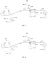
- FIG. 3 is a schematic diagram of a winding and unwinding system in a first working state according to an embodiment of this application.
- FIG. 4 is a schematic diagram of a winding and unwinding system in a second working state according to an embodiment of this application.
- FIG. 5 is a schematic diagram of a winding and unwinding system in a third working state according to an embodiment of this application.
- the winding and unwinding system 100 includes at least two winding rollers 120, a roll-changing device 130, a sensing device 150, a measuring device 140, and a controller.
- the roll-changing device 130 is able to drive at least two winding rollers 120 to sequentially move to a set position, where a winding roller 120 located at the set position is able to wind a strip material 200.
- the sensing device 150 emits an in-place signal when the winding roller 120 located at the set position rotates one circle.
- the measuring device 140 is configured to measure a traveling length of the strip material 200.
- the controller is connected to the sensing device 150, the measuring device 140, and the roll-changing device 130, where the controller, in response to receiving the in-place signal, determines a winding radius of the winding roller 120 located at the set position based on the traveling length measured by the measuring device 140; and the controller sends a roll-changing signal to the roll-changing device 130 when the winding radius reaches a preset threshold, where the roll-changing device 130, upon receiving the roll-changing signal, drives another winding roller 120 to move to the set position and get in contact with the strip material 200, so that the strip material 200 winds onto the another winding roller 120.
- the winding and unwinding system 100 may include a first motor and a second motor.
- the first motor is configured to drive the winding roller 120 located at the set position to rotate, and the strip material 200 winds onto the winding roller 120 with the rotation of the winding roller 120.
- the winding radius r refers to radius of a winding roller.
- the winding radius r being determined as having reached the preset threshold can be used to characterize the situation that the winding radius r is approaching or reaching the maximum roll radius.
- the winding and unwinding system 100 can automatically change the roll of the winding roller 120.
- the roll changing principle is as follows: the controller sends a roll-changing signal to the roll-changing device 130, and the roll-changing device 130, upon receiving the roll-changing signal, drives another winding roller 120 to move to the set position and get in contact with the strip material 200.
- the second motor is configured to drive the another winding roller 120, which has moved to the set position, to rotate.
- the strip material 200 winds onto the another winding roller 120 with the rotation of the another winding roller 120.
- the roll-changing device 130 may include a base 131 and a rod 132, as shown in FIG. 3 to FIG. 5 .
- the base 131 is mounted on the ground, and the rod 132 is rotatably mounted on the base 131.
- the two winding rollers 120 are connected to two ends of the rod 132, respectively.
- FIG. 6 is a schematic diagram of another winding and unwinding system 100 in a first working state according to an embodiment of this application.
- FIG. 7 is a schematic diagram of another winding and unwinding system 100 in a second working state according to an embodiment of this application.
- FIG. 8 is a schematic diagram of another winding and unwinding system 100 in a third working state according to an embodiment of this application.
- the roll-changing device 130 may further include a rotating plate 133. One end of each of the two winding rollers 120 is connected to the rotating plate 133. The rotating plate 133 changes the positions of the two winding rollers 120 through rotation, so that the two winding rollers 120 can sequentially move to the set position.
- the winding and unwinding system 100 of this embodiment can determine the current circumference of the winding roller 120 by measuring the traveling length of the strip material 200 for one circle of rotation of the winding roller 120, thereby obtaining the current winding radius of the winding roller 120.
- This eliminates the need for an ultrasonic distance measuring sensor, not only saving costs but also providing high measurement accuracy, which helps avoid errors in estimating the number of winding layers due to measurement errors.
- the method of measuring the winding radius in the winding and unwinding system 100 of this embodiment is independent of thickness and tension of the strip material 200, and therefore is not affected by thickness of the electrode sheet and interlayer spacing of the electrode sheet, providing high measurement accuracy.
- the winding and unwinding system 100 is also designed to automatically change the winding roller 120, when the winding radius reaches a preset threshold, by controlling the roll-changing device 130. This allows a new winding roller 120 to move to the set position to wind the strip material 200, and the strip material 200 automatically winds onto the winding roller 120. The winding and unwinding system 100 can then start measuring the winding radius of the new winding roller 120, optimizing the roll-changing process and improving production efficiency.
- the sensing device 150 may include a light-emitting device 151 and a receiving device 152, where the light-emitting device 151 is configured to emit a photoelectric signal, and the receiving device 152 is configured to receive the photoelectric signal, where when the winding roller 120 located at the set position rotates one circle, a state of reception of the photoelectric signal by the receiving device 152 changes and the receiving device emits the in-place signal.
- the light-emitting device 151 may be mounted at one end of the winding roller 120 along a rotation axis, and rotate synchronously with the winding roller 120 under the driving of the winding roller 120. Each time the winding roller 120 rotates one circle, the photoelectric signal emitted by the light-emitting device 151 changes from not entering the receiving device 152 to entering the receiving device 152.
- the receiving device 152 emits an in-place signal when its state of reception of the photoelectric signal changes from a non-receiving state to a receiving state.
- the sensing device 150 is a photoelectric switch, which has the advantage of high detection accuracy.
- the receiving device 152 may also be configured to emit an in-place signal when its state of reception of the photoelectric signal changes from a receiving state to a non-receiving state.
- the light-emitting device 151 and the receiving device 152 are fixed and disposed opposite each other, and the winding roller 120 located at the set position is mounted with a light-blocking member, where the light-blocking member is able to rotate with the winding roller 120 to a position between the light-emitting device 151 and the receiving device 152 and block the photoelectric signal.
- the light-blocking member may be mounted at one end of the winding roller 120 along the rotation axis, and rotate synchronously with the winding roller 120 under the driving of the winding roller 120. After the light-blocking member rotates one circle with the winding roller 120, the light-blocking member rotates to a position between the light-emitting device 151 and the receiving device 152 and blocks the photoelectric signal. The state of reception of the photoelectric signal by the receiving device 152 changes from the receiving state to the non-receiving state.
- the light-emitting device 151 and the receiving device 152 may be separate components. With this arrangement, the sensing device 150 emits the in-place signal based on the rotation of the winding roller 120, cooperating with the controller for measurement.
- the sensing device 150 is a slot-type photoelectric switch or a through-beam photoelectric switch.
- the slot-type photoelectric switch has the advantages of low cost, fast response, and small space occupation.
- the switch is easy to obtain through purchase.
- the light-emitting device 151 and the receiving device are 152 integrated into a single component, eliminating the need for separate installations.
- the sensing device 150 may also be replaced with a Hall effect proximity switch or the like.
- the winding and unwinding system 100 further includes a traction mechanism 160, where the traction mechanism 160 is located upstream of the winding roller 120 in a conveying direction of the strip material 200, to pull the strip material 200 and convey it to the winding roller 120 located at the set position
- the traction mechanism 160 where the traction mechanism 160 is configured to apply traction to the strip material 200, the strip material 200 is pulled and conveyed in a direction approaching the winding roller 120.
- the traction mechanism 160 may specifically include a traction motor 163, a driving traction roller 161, and a driven traction roller 162, where the driving traction roller 161 is drivingly connected to the traction motor 163, and the strip material 200 passes between the driving traction roller 161 and the driven traction roller 162.
- the measuring device 140 can determine the traveling length of the strip material 200 by measuring a rotation angle or a rotation displacement of the driving traction roller 161 or the driven traction roller 162.
- the rotation displacement of the driving traction roller 161 and the driven traction roller 162 is the traveling length of the strip material 200.
- the traveling length of the strip material 200 is the circumference of the driving traction roller 161 and the driven traction roller 162.
- the measuring device 140 can directly measure the rotation displacement of the driving traction roller 161 or the driven traction roller 162, or can determine the rotation displacement by measuring a rotation angle of the driving traction roller 161 or the driven traction roller 162, and then determining the rotation displacement based on the rotation angle.
- the measuring device 140 may be a rotary encoder, where the rotary encoder is provided on the driving traction roller 161 or the driven traction roller 162 to detect the rotation angle of the traction roller; or the measuring device 140 may also be an angle sensor.
- the measuring device 140 may also be provided on the traction motor 163.
- the measuring device 140 is configured to obtain the number of pulses of the traction motor 163. Based on the number of pulses, the rotation angle of the traction motor 163 can be determined. Based on the transmission ratio between the traction motor 163 and the driving traction roller 161, the rotation angle of the driving traction roller 161 can be determined.
- the measuring device 140 is a meter wheel, and the meter wheel is in contact with a surface of the driving traction roller 161 or the driven traction roller 162.
- the winding and unwinding system 100 may further include a fixed base 141, a connecting rod 142, and a cylinder 143.
- One end of the connecting rod 142 is connected to the fixed base 141, and another end of the connecting rod 142 is connected to the meter wheel.
- the cylinder 143 is fixedly mounted on the fixed base 141, and the telescopic rod of the cylinder 143 is connected to the connecting rod 142.
- the telescopic rod of the cylinder 143 extends and retracts to drive the connecting rod 142 to move, so that the meter wheel can abut against the driving traction roller 161 or the driven traction roller 162.
- the principle by which the measuring device 140 measures the traveling length of the strip material 200 is as follows: the driven traction roller 162 rotates to pull the strip material 200 to move, and the meter wheel rotates with the rotation of the driven traction roller 162, detecting the rotation displacement of the driven traction roller 162. Based on this, the traveling length of the strip material 200 can be directly determined.
- the traveling length of the strip material 200 can be directly determined, eliminating the need for conversion and resulting in a small amount of calculation.
- the meter wheel is not in contact with the strip material 200, avoiding affecting the strip material 200 due to contact between the meter wheel and the active material layer on the strip material 200. It should also be noted that, compared with the meter wheel abutting against the winding roller 120 located at the set position, the arrangement of the meter wheel abutting against the surface of the driving traction roller 161 or the driven traction roller 162 prevents the meter wheel from affecting the winding of the strip material 200 by the winding roller 120.
- the winding and unwinding system 100 may further include a driving device 171 and a roll-changing pressing roller 170, where the roll-changing pressing roller 170 is drivingly connected to the driving device 171, and the driving device 171 is connected to the controller.
- the controller sends a roll-pressing signal to the driving device 171 when the winding radius reaches the preset threshold, and the driving device 171, upon receiving the roll-pressing signal, drives the roll-changing pressing roller 170 to move close to the set position, so that the roll-changing pressing roller 170 gets in contact with the strip material 200.
- the controller is not limited to sending the roll-changing signal and the roll-pressing signal simultaneously.
- the controller can alternatively send the roll-changing signal first and then send the roll-pressing signal.
- the circumferential surface of the winding roller 120 may further be provided with an adhesive layer.
- An example working principle of the winding and unwinding system 100 in this embodiment is as follows: the controller first sends the roll-changing signal to the roll-changing device 130 when the winding radius reaches the preset threshold.
- the roll-changing device 130 upon receiving the roll-changing signal, drives another winding roller 120 to move to the set position.
- the another winding roller 120 can get in contact with the strip material 200 and start winding.
- the controller then sends the roll-pressing signal to the driving device 171.
- the driving device 171 upon receiving the roll-pressing signal, drives the roll-changing pressing roller 170 to move close to the set position so that the roll-changing pressing roller 170 gets in contact with the strip material 200.
- the roll-changing pressing roller 170 applies pressure to the strip material 200, enabling a reliable connection between the strip material 200 and the adhesive layer to ensure that the strip material 200 can wind onto the winding roller 120.
- the new winding roller 120 winds the strip material 200, and the roll-changing pressing roller 170 can move to get in contact with the strip material 200 to apply pressure to the strip material 200, ensuring that the strip material 200 can wind onto the new winding roller 120.
- the driving device 171 may be configured to drive the roll-changing pressing roller 170 to move in the vertical direction.
- the driving device 171 upon receiving the roll-pressing signal, can drive the roll-changing pressing roller 170 to move up a preset height to get in contact with the strip material 200, and then the driving device 171 can stop driving the roll-changing pressing roller 170 to move up.
- the roll-changing pressing roller 170 may be provided with a contact sensor.
- the driving mechanism stops when the contact sensor detects that the roll-changing pressing roller 170 is in contact with the strip material 200 to prevent the driving mechanism from continuing to drive the roll-changing pressing roller 170 upward, causing the roll-changing pressing roller 170 to collide with the winding roller 120.
- the controller can control the driving mechanism to drive the roll-changing pressing roller 170 to move up a preset height based on the measured winding radius.
- the driving device 171 may be configured to include an oscillating arm 1712 and a servo motor 1711, where one end of the oscillating arm 1712 is connected to the roll-changing pressing roller 170, and another end of the oscillating arm 1712 is drivingly connected to the servo motor 1711, the servo motor 1711 being connected to the controller.
- the servo motor 1711 can drive the oscillating arm 1712 to rotate, driving the roll-changing pressing roller 170 to rotate to a position close to the set position and get in contact with the strip material 200.
- the controller can control the driving mechanism to drive the roll-changing pressing roller 170 to rotate by a preset angle based on the measured winding radius. When the roll-changing pressing roller 170 rotates by the preset angle, it just gets in contact with the strip material 200.
- the winding and unwinding system 100 may further include a cutting device connected to the controller.
- the controller can send a cutting signal to the cutting device, and the cutting device, upon receiving the cutting signal, cuts off the strip material 200 wound between the two winding rollers 120. In this way, one winding roller 120 completes winding, and the another winding roller 120 starts winding the strip material 200.
- the winding and unwinding system 100 may further include an unwinding roller 110, where the unwinding roller 110 is configured to unwind the strip material 200, and the unwinding roller 110 is located upstream of the winding roller 120 in the conveying direction of the strip material 200.
- the winding and unwinding system 100 further includes a third motor 111, where the third motor 111 drives the unwinding roller 110 to rotate.
- the unwinding roller 110 rotates in a same direction as the winding roller 120, and the diameter of the unwinding roller 110 may be the same as or different from the diameter of the winding roller 120.
- An unwinding length of the unwinding roller 110 is a winding length of the winding roller 120. It should be noted that when the diameter of the unwinding roller 110 is the same as the diameter of the winding roller 120, the sensing device 150 may alternatively emit the in-place signal when the unwinding roller 110 rotates one circle.
- the winding and unwinding system 100 of this embodiment can measure the traveling length of the strip material 200 when the winding roller 120 rotates one circle. Since the unwinding roller 110 rotates in a same direction as the winding roller 120, the current unwinding radius of the unwinding roller 110 can be measured, and further, the number of layers of the strip material 200 wound on the unwinding roller 110 can be calculated accordingly.
- the winding and unwinding system 100 of this embodiment has higher measurement accuracy, which helps avoid errors in estimating the number of layers of the strip material 200 wound on the unwinding roller 110 due to measurement errors, thereby avoiding waste caused by the unwinding roller 110 automatically changing rolls prematurely.
- the embodiments of this application further provide a preparation device for a battery electrode sheet, where the preparation device is configured to make battery electrode sheets and may include the winding and unwinding system 100 according to any one of the above embodiments.
- the preparation device can use the rolled electrode sheets and separators produced by the winding and unwinding system 100 for winding to prepare electrode assemblies.
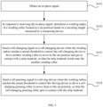
- FIG. 9 is a schematic flowchart of a winding and unwinding method according to an embodiment of this application.
- the embodiments of this application further provide a winding and unwinding control method, where the winding and unwinding control method is suitable for controlling the winding and unwinding system 100 according to any one of the above embodiments.
- the control method may include step S101 to step S103.
- Step S103 Send a roll-changing signal to the roll-changing device 130 when the winding radius reaches a preset threshold to control the roll-changing device 130 to drive another winding roller 120 to move to the set position and get in contact with the strip material 200, so that the strip material 200 winds onto the another winding roller 120.
- a current circumference of the winding roller 120 can be determined through measurement of a traveling length of the strip material 200 when the winding roller 120 rotates one circle, thereby the current winding radius of the winding roller 120 can be obtained.
- the method of measuring the winding radius in the winding and unwinding system 100 of this embodiment is independent of thickness and tension of the strip material 200, and therefore is not affected by thickness of the electrode sheet and interlayer spacing of the electrode sheet, providing high measurement accuracy.
- control method may further include step S104.
- Step S104 Send a roll-pressing signal to the driving device 171 when the winding radius reaches the preset threshold to control the driving device 171 to drive the roll-changing pressing roller 170 to move close to the set position, so that the roll-changing pressing roller 170 gets in contact with the strip material 200.
- the roll-pressing signal and the roll-changing signal may be sent simultaneously, or the roll-changing signal may be sent first, followed by the roll-pressing signal.
- the roll-changing pressing roller 170 can be controlled to move to get in contact with the strip material 200 to apply pressure to the strip material 200, ensuring that the strip material 200 can wind onto the new winding roller 120.
- this control method may further include step S105.
- Step S105 Send a cutting signal to the cutting device to control the cutting device to cut off the strip material 200 wound between the two winding rollers 120. In this way, automatic roll changing is implemented.
- the winding and unwinding system 100 may include: at least two winding rollers 120, a roll-changing device 130, a light-emitting device, a receiving device, a meter wheel, a traction mechanism 160, and a controller.
- the traction mechanism 160 may specifically include a traction motor 163, a driving traction roller 161, and a driven traction roller 162.
- the driving traction roller 161 is drivingly connected to the traction motor 163, and the strip material 200 passes between the driving traction roller 161 and the driven traction roller 162.
- the meter wheel is in contact with the surface of the driven traction roller 162.
- the roll-changing device 130 is able to drive at least two winding rollers 120 to sequentially move to a set position, where a winding roller 120 located at the set position is able to wind a strip material 200.
- Each winding roller 120 is provided with a light-blocking member at one end along the rotation axis. After the light-blocking member rotates one circle with the winding roller 120, the light-blocking member rotates to a position between the light-emitting device and the receiving device, blocking the photoelectric signal.
- the receiving device 152 emits an in-place signal to the controller.
- the controller determines the circumference of the winding roller 120 at the set position for one circle of rotation based on the traveling length of the strip material 200 measured by the meter wheel, thereby obtaining the winding radius of the winding roller 120 at the set position.
- the controller When the winding radius reaches the preset threshold, the controller sends a roll-changing signal to the roll-changing device 130.
- the roll-changing device 130 upon receiving the roll-changing signal, drives another winding roller 120 to move to the set position and get in contact with the strip material 200, so that the strip material 200 winds onto the another winding roller 120.
Landscapes
- Engineering & Computer Science (AREA)
- Manufacturing & Machinery (AREA)
- Chemical & Material Sciences (AREA)
- Chemical Kinetics & Catalysis (AREA)
- Electrochemistry (AREA)
- General Chemical & Material Sciences (AREA)
- Controlling Rewinding, Feeding, Winding, Or Abnormalities Of Webs (AREA)
Abstract
Description
- This application refers to
Chinese Patent Application No. 202211124550.5, filed on September 15, 2022 - This application relates to the field of battery technologies, and in particular, to a winding and unwinding system, a control method, and a preparation device for a battery electrode sheet.
- Energy saving and emission reduction are crucial to the sustainable development of the automobile industry. Electric vehicles, with their advantages in energy conservation and emission reduction, have become an important part of sustainable development of the automobile industry. For electric vehicles, battery technology is an important factor in connection with their development.
- During the winding of battery electrode sheets, to implement taper tension control, it is necessary to detect the winding radius to adjust the tension based on the winding radius. However, the measurement accuracy of common winding radius measurement methods is low.
- This application is intended to resolve at least one of the foregoing technical problems in the prior art. In view of this, an objective of this application is to provide a winding and unwinding system, a control method, and a preparation device for a battery electrode sheet to improve the measurement accuracy of the winding radius.
- Embodiments of a first aspect of this application provide a winding and unwinding system, including at least two winding rollers, a roll-changing device, a sensing device, a measuring device, and a controller. The roll-changing device is able to drive the at least two winding rollers to sequentially move to a set position, where a winding roller located at the set position is able to wind a strip material; the sensing device emits an in-place signal when the winding roller located at the set position rotates one circle; and the measuring device is configured to measure a traveling length of the strip material. The controller is connected to the sensing device, the measuring device, and the roll-changing device, where the controller, in response to receiving the in-place signal, determines a winding radius of the winding roller located at the set position based on the traveling length measured by the measuring device; and the controller sends a roll-changing signal to the roll-changing device when the winding radius reaches a preset threshold, where the roll-changing device, upon receiving the roll-changing signal, drives another winding roller to move to the set position and get in contact with the strip material, so that the strip material winds onto the another winding roller.
- In the technical solution of the embodiments of this application, the current circumference of the winding roller can be determined by measuring the traveling length of the strip material when the winding roller rotates one circle, and the current winding radius of the winding roller can be obtained accordingly. This eliminates the need for an ultrasonic distance measuring sensor, not only saving costs but also providing high measurement accuracy, which helps avoid errors in estimating the number of winding layers due to measurement errors. Moreover, the method of measuring the winding radius in the winding and unwinding system of this embodiment is independent of thickness and tension of the strip material, and therefore is not affected by thickness of the electrode sheet and interlayer spacing of the electrode sheet, providing high measurement accuracy.
- In some embodiments, the sensing device includes a light-emitting device and a receiving device, where the light-emitting device is configured to emit a photoelectric signal, and the receiving device is configured to receive the photoelectric signal, where when the winding roller located at the set position rotates one circle, a state of reception of the photoelectric signal by the receiving device changes and the receiving device emits the in-place signal. With this arrangement, the sensing device is a photoelectric switch, which has the advantage of high detection accuracy.
- In some embodiments, the light-emitting device and the receiving device are fixed and are disposed opposite each other, and the winding roller located at the set position is provided with a light-blocking member, where the light-blocking member is able to rotate with the winding roller to a position between the light-emitting device and the receiving device and block the photoelectric signal. With this arrangement, the sensing device emits the in-place signal based on the rotation of the winding roller, cooperating with the controller for measurement.
- In some embodiments, the sensing device is a slot-type photoelectric switch or a through-beam photoelectric switch. The slot-type sensing device provided as a slot-type photoelectric switch or a through-beam photoelectric switch is easy to obtain through purchase. The light-emitting device and the receiving device are integrated into a single component, eliminating the need for separate installations.
- In some embodiments, the winding and unwinding system includes a traction mechanism, where the traction mechanism is located upstream of the winding roller in a conveying direction of the strip material to pull the strip material and convey it to the winding roller located at the set position. The traction mechanism can be configured to apply traction to the strip material to pull the strip material and convey it in a direction approaching the winding roller.
- In some embodiments, the traction mechanism includes a traction motor, a driving traction roller, and a driven traction roller, where the driving traction roller is drivingly connected to the traction motor, and the strip material passes between the driving traction roller and the driven traction roller; and the measuring device determines the traveling length of the strip material by measuring a rotation angle or a rotation displacement of the driving traction roller or the driven traction roller.
- In some embodiments, the measuring device is a meter wheel, and the meter wheel is in contact with a surface of the driving traction roller or the driven traction roller. In this embodiment, with the meter wheel provided as in contact with a surface of the driving traction roller or the driven traction roller to detect the rotation displacement of the driving traction roller or the driven traction roller, the traveling length of the strip material can be directly determined, eliminating the need for conversion and resulting in a small amount of calculation. Moreover, compared with the meter wheel being in contact with a surface of the strip material to measure the traveling length of the strip material, in this embodiment, the meter wheel is not in contact with the strip material, avoiding affecting the strip material due to contact between the meter wheel and the active material layer on the strip material.
- It some embodiments, a driving device and a roll-changing pressing roller drivingly connected to the driving device is further included, where the driving device is connected to the controller; where the controller sends a roll-pressing signal to the driving device when the winding radius reaches the preset threshold, and the driving device, upon receiving the roll-pressing signal, drives the roll-changing pressing roller to move close to the set position, so that the roll-changing pressing roller gets in contact with the strip material. With this design, after the roll is changed, a new winding roller winds the strip material, and the roll-changing pressing roller can move to get in contact with the strip material to apply pressure to the strip material, ensuring that the strip material can wind onto the new winding roller.
- In some embodiments, the driving device includes an oscillating arm and a servo motor, where one end of the oscillating arm is connected to the roll-changing pressing roller, and another end of the oscillating arm is drivingly connected to the servo motor, the servo motor being connected to the controller.
- In some embodiments, the winding and unwinding system further includes an unwinding roller, where the unwinding roller is configured to unwind the strip material, and the unwinding roller is located upstream of the winding roller in the conveying direction of the strip material.
- Compared with the winding radius measuring performed by using the ultrasonic distance measuring sensor, the winding and unwinding system of this embodiment has higher measurement accuracy, which helps avoid errors in estimating the number of layers of the strip material wound on the unwinding roller due to measurement errors, thereby avoiding waste caused by the unwinding roller automatically changing rolls prematurely.
- Embodiments of a second aspect of this application provide a preparation device for a battery electrode sheet, which includes the winding and unwinding system provided in the embodiments of the first aspect of this application.
- Embodiments of a third aspect of this application provide a winding and unwinding control method applicable to the winding and unwinding system provided in the embodiments of the first aspect of this application. The control method includes: obtaining an in-place signal; determining, in response to receiving the in-place signal, a winding radius of the winding roller located at the set position based on the traveling length measured by the measuring device; and sending a roll-changing signal to the roll-changing device when the winding radius reaches a preset threshold to control the roll-changing device to drive another winding roller to move to the set position and get in contact with the strip material, so that the strip material winds onto the another winding roller.
- In some embodiments, after the determining a winding radius of the winding roller located at the set position based on the traveling length measured by the measuring device, the control method further includes: sending a roll-pressing signal to the driving device when the winding radius reaches the preset threshold to control the driving device to drive the roll-changing pressing roller to move close to the set position, so that the roll-changing pressing roller gets in contact with the strip material.
- The foregoing description is merely an overview of the technical solution of this application. For a better understanding of the technical means in this application such that they can be implemented according to the content of the specification, and to make the above and other objectives, features and advantages of this application more obvious and easier to understand, the following describes specific embodiments of this application.
- In the accompanying drawings, unless otherwise specified, same reference signs throughout a plurality of accompanying drawings indicate the same or similar components or elements. These accompanying drawings may not necessarily be drawn to scale. It should be understood that these accompanying drawings illustrate only some embodiments disclosed in this application and should not be construed as limitations on the scope of this application. To describe the technical solutions in the embodiments of this application more clearly, the following briefly describes the accompanying drawings required for describing the embodiments of this application. Apparently, the accompanying drawings in the following descriptions show merely some embodiments of this application, and persons of ordinary skill in the art may still derive other drawings from the accompanying drawings without creative efforts.
-
FIG. 1 is a schematic diagram of a winding and unwinding system in a related example; -
FIG. 2 is a schematic diagram of another winding and unwinding system in a related example; -
FIG. 3 is a schematic diagram of a winding and unwinding system in a first working state according to an embodiment of this application; -
FIG. 4 is a schematic diagram of a winding and unwinding system in a second working state according to an embodiment of this application; -
FIG. 5 is a schematic diagram of a winding and unwinding system in a third working state according to an embodiment of this application; -
FIG. 6 is a schematic diagram of another winding and unwinding system in a first working state according to an embodiment of this application; -
FIG. 7 is a schematic diagram of another winding and unwinding system in a second working state according to an embodiment of this application; -
FIG. 8 is a schematic diagram of another winding and unwinding system in a third working state according to an embodiment of this application; and -
FIG. 9 is a schematic flowchart of a winding and unwinding method according to an embodiment of this application. - Description of reference signs:
- 100-winding and unwinding system;
- 110-unwinding roller; 111-third motor;
- 120-winding roller;
- 130-roll-changing device; 131-base; 132-rod; 133-rotating plate;
- 140-measuring device; 141-fixed base; 142-connecting rod; 143-cylinder;
- 150-sensing device; 151-light-emitting device; 152-receiving device;
- 160-traction mechanism; 161-driving traction roller; 162-driven traction roller; 163-traction motor;
- 170-roll-changing pressing roller; 171-driving device; 1711-servo motor; 1712-oscillating arm; and
- 200-strip material.
- The following describes in detail the embodiments of technical solutions of this application with reference to the accompanying drawings. The following embodiments are merely intended for a clearer description of the technical solutions of this application and therefore are used as just examples which do not constitute any limitations on the protection scope of this application.
- Unless otherwise defined, all technical and scientific terms used herein shall have the same meanings as commonly understood by those skilled in the art to which this application belongs. The terms used herein are merely intended to describe the specific embodiments but not intended to constitute any limitation on this application. The terms "include", "have", and any other variations thereof in the specification, the claims and the foregoing brief description of drawings of this application are intended to cover a non-exclusive inclusion.
- In descriptions of embodiments of this application, the terms "first", "second" and the like are merely intended to distinguish between different objects, and shall not be understood as any indication or implication of relative importance or any implicit indication of the number, specific sequence or primary-secondary relationship of the technical features indicated. In the descriptions of this application, "a plurality of" means at least two unless otherwise specifically stated.
- In this specification, reference to "embodiment" means that specific features, structures or characteristics described with reference to the embodiment may be incorporated in at least one embodiment of this application. The word "embodiment" appearing in various places in the specification does not necessarily refer to the same embodiment or an independent or alternative embodiment that is exclusive of other embodiments. Persons skilled in the art explicitly and implicitly understand that the embodiments described herein may be combined with other embodiments.
- In the descriptions of the embodiments of this application, the term "and/or" is only an associative relationship for describing associated objects, indicating that three relationships may be present. For example, A and/or B may indicate the following three cases: presence of only A, presence of both A and B, and presence of only B. In addition, the character "/" in this specification generally indicates an "or" relationship between contextually associated objects.
- In the description of the embodiments of this application, the term "a plurality of" means more than two (inclusive). Similarly, "a plurality of groups" means more than two (inclusive) groups, and "a plurality of pieces" means more than two (inclusive) pieces.
- In the description of the embodiments of this application, the orientations or positional relationships indicated by the technical terms "center", "longitudinal", "transverse", "length", "width", "thickness", "upper", "lower", "front", "rear", "left", "right", "vertical", "horizontal", "top", "bottom", "inside", "outside", "clockwise", "counterclockwise", "axial", " radial", "circumferential", and the like are based on the orientations or positional relationships as shown in the accompanying drawings. These terms are merely for ease and brevity of description of the embodiments of this application rather than indicating or implying that the means or components mentioned must have specific orientations or must be constructed or manipulated according to specific orientations, and therefore shall not be construed as any limitations on the embodiments of this application.
- In the descriptions of the embodiments of this application, unless otherwise specified and defined explicitly, the technical terms "mount", "connect", "join", and "fix" should be understood in their general senses. For example, they may refer to a fixed connection, a detachable connection, or an integral connection, may refer to a mechanical connection or an electrical connection, and may refer to a direct connection, an indirect connection via an intermediate medium, an internal communication between two elements, or an interaction between two elements. Persons of ordinary skill in the art can understand specific meanings of these terms in this application as appropriate to specific situations.
- Batteries are widely used in energy storage power systems, electric transportation tools, military equipment, and aerospace. A battery mainly includes electrode assemblies. An electrode assembly, which serves as a storage component, is mainly composed of a positive electrode sheet, a negative electrode sheet, and a separator. Operation of the battery mainly relies on migration of metal ions between the positive electrode sheet and the negative electrode sheet. Both the positive electrode sheet and the negative electrode sheet include a current collector and an active material layer, where the active material layer is applied on a surface of the current collector. The production process of the electrode sheets typically involves: using a coating device to apply an active material layer onto an electrode sheet. The electrode sheet coated with the active material layer is then conveyed to a roller pressing device, where the roller pressing device presses the electrode sheet to compact the current collector and the active material layer. After that, the electrode sheet is further conveyed to the winding roller for winding.
- When winding is performed with constant tension, as the winding radius increases, the outer layers of the electrode sheet tend to slip and slide axially along the winding roller, while the inner layers close to the winding roller are prone to wrinkling. To solve this problem, taper tension control is usually required during winding, which means adjusting the tension based on a change in the winding radius and decreasing the tension as the winding radius increases. Therefore, it is necessary to measure the winding radius.
-
FIG. 1 is a schematic diagram of a winding and unwinding system in a related example. In some examples, as shown inFIG. 1 , an ultrasonicdistance measuring sensor 180a may be used to directly detect the winding radius. The working principle of measuring the winding radius in this example is as follows: a distance between the ultrasonicdistance measuring sensor 180a and the center of the windingroller 120a is a fixed value L1. The ultrasonicdistance measuring sensor 180a can detect a distance L2 between itself and the windingroller 120a, so the winding radius is L1 - L2. However, there are the following problems with using the ultrasonicdistance measuring sensor 180a to detect the winding radius: first, the cost of the ultrasonicdistance measuring sensor 180a is high; second, a detection accuracy of the ultrasonicdistance measuring sensor 180a is ±0.5 mm; however, thickness of theelectrode sheet 200a is usually 4-6 micrometers (µm). Thus, when there is a detection error of, for example, -0.5 millimeters (mm) in the detection performed by the ultrasonicdistance measuring sensor 180a, the theoretical number of layers of theelectrode sheet 200a wound on the windingroller 120a calculated based on this is far greater than the actual number of layers of theelectrode sheet 200a wound on the windingroller 120a, leading to an error in estimating the number of layers of theelectrode sheet 200a wound on the windingroller 120a. When a diameter of the windingroller 120a is equal to a diameter of the unwinding roller, the number of layers of theelectrode sheet 200a wound on the windingroller 120a is equal to the number of layers of theelectrode sheet 200a unwound from the unwinding roller. Accordingly, the theoretical number of layers of theelectrode sheet 200a unwound from the unwinding roller calculated is far greater than the actual number of layers of theelectrode sheet 200a unwound from the unwinding roller, leading to an error in estimating the actual number of layers of theelectrode sheet 200a unwound from the unwinding roller, and when causing the unwinding roller to automatically change rolls prematurely, this results in waste. -
FIG. 2 is a schematic diagram of another winding and unwinding system in a related example. In other examples, as shown inFIG. 2 , the winding and unwinding system 100a includes an unwindingroller 110a, a windingroller 120a, athickness measuring device 190a, aproximity switch 150a, and acounter 191a. The unwindingroller 110a is configured to unwind theelectrode sheet 200a. The windingroller 120a is configured to wind theelectrode sheet 200a. In the conveying direction of theelectrode sheet 200a, thethickness measuring device 190a is located downstream of the unwindingroller 110a and is configured to measure the thickness h of theelectrode sheet 200a. Theproximity switch 150a is configured to emit a signal to thecounter 191a when the unwindingroller 110a winds one circle, and thecounter 191a counts in response to receiving the signal. Taking the diameter of the windingroller 120a being equal to the diameter of the unwindingroller 110a as an example, the working principle of measuring the winding radius in this example is as follows: each time the unwindingroller 110a rotates one circle, the unwinding radius decreases by 2h. The initial diameter of the unwindingroller 110a is D0, and when the unwindingroller 110a rotates N circles, the unwinding radius R = (D0 - 2hN)/2. Accordingly, the winding radius r = (D0 + 2hN)/2. However, due to the precision limitations of the roller pressing device and the limitations of the coating process, the thickness of theelectrode sheet 200a is uneven. Therefore, when this method is used to detect the winding radius, the thickness of theelectrode sheet 200a affects the accuracy of the winding radius calculation. - In view of this, the applicant proposes a winding and unwinding system. This winding and unwinding system uses a measuring device to measure the traveling length of the strip material when the winding roller rotates one circle. From this, the circumference of the winding roller for one circle of rotation can be determined, thereby allowing the calculation of the winding radius of the winding roller.
- The winding and unwinding system disclosed in the embodiments of this application can be applied to winding various types of strip materials. For example, the strip materials may refer to battery electrode sheets, specifically, the strip materials may be positive electrode sheets or negative electrode sheets; or the strip materials may also refer to steel strips, adhesive tapes, cloth tapes, or paper tapes. This is not specifically limited in this embodiment of this application. When the strip material is an electrode sheet, the strip material specifically includes a metal foil (such as copper foil or aluminum foil) and an active material layer. In this case, the winding and unwinding system may specifically be used for the die-cutting process of the electrode sheet.
-
FIG. 3 is a schematic diagram of a winding and unwinding system in a first working state according to an embodiment of this application.FIG. 4 is a schematic diagram of a winding and unwinding system in a second working state according to an embodiment of this application.FIG. 5 is a schematic diagram of a winding and unwinding system in a third working state according to an embodiment of this application. Referring toFIG. 3 to FIG. 5 , according to some embodiments of this application, the winding andunwinding system 100 includes at least two windingrollers 120, a roll-changingdevice 130, asensing device 150, a measuringdevice 140, and a controller. The roll-changingdevice 130 is able to drive at least two windingrollers 120 to sequentially move to a set position, where a windingroller 120 located at the set position is able to wind astrip material 200. Thesensing device 150 emits an in-place signal when the windingroller 120 located at the set position rotates one circle. The measuringdevice 140 is configured to measure a traveling length of thestrip material 200. - The controller is connected to the
sensing device 150, the measuringdevice 140, and the roll-changingdevice 130, where the controller, in response to receiving the in-place signal, determines a winding radius of the windingroller 120 located at the set position based on the traveling length measured by the measuringdevice 140; and the controller sends a roll-changing signal to the roll-changingdevice 130 when the winding radius reaches a preset threshold, where the roll-changingdevice 130, upon receiving the roll-changing signal, drives another windingroller 120 to move to the set position and get in contact with thestrip material 200, so that thestrip material 200 winds onto the another windingroller 120. - The winding and
unwinding system 100 may include a first motor and a second motor. The first motor is configured to drive the windingroller 120 located at the set position to rotate, and thestrip material 200 winds onto the windingroller 120 with the rotation of the windingroller 120. - The working principle of measuring the winding radius in this embodiment is as follows: when the winding
roller 120 located at the set position rotates one circle, thesensing device 150 emits an in-place signal. At this time, the controller determines that the traveling length measured by the measuringdevice 140 is the current circumference C of the windingroller 120. According to the circumference calculation formula C = 2πr, the current winding radius r of the windingroller 120 can be obtained. The winding radius r refers to radius of a winding roller. - The winding radius r being determined as having reached the preset threshold can be used to characterize the situation that the winding radius r is approaching or reaching the maximum roll radius. At this time, the winding and
unwinding system 100 can automatically change the roll of the windingroller 120. The roll changing principle is as follows: the controller sends a roll-changing signal to the roll-changingdevice 130, and the roll-changingdevice 130, upon receiving the roll-changing signal, drives another windingroller 120 to move to the set position and get in contact with thestrip material 200. The second motor is configured to drive the another windingroller 120, which has moved to the set position, to rotate. Thestrip material 200 winds onto the another windingroller 120 with the rotation of the another windingroller 120. - Taking a situation where two winding
rollers 120 are provided as an example, the roll-changingdevice 130, for example, may include abase 131 and arod 132, as shown inFIG. 3 to FIG. 5 . Thebase 131 is mounted on the ground, and therod 132 is rotatably mounted on thebase 131. The two windingrollers 120 are connected to two ends of therod 132, respectively. When the winding andunwinding system 100 is in the first working state, one of the windingrollers 120 is located in the set position, and therod 132 of the roll-changingdevice 130 rotates upon receiving the roll-changing signal, so that the other windingroller 120 moves to the set position. -
FIG. 6 is a schematic diagram of another winding andunwinding system 100 in a first working state according to an embodiment of this application.FIG. 7 is a schematic diagram of another winding andunwinding system 100 in a second working state according to an embodiment of this application.FIG. 8 is a schematic diagram of another winding andunwinding system 100 in a third working state according to an embodiment of this application. Alternatively, in another embodiment, as shown inFIG. 6 to FIG. 8 , the roll-changingdevice 130 may further include arotating plate 133. One end of each of the two windingrollers 120 is connected to therotating plate 133. Therotating plate 133 changes the positions of the two windingrollers 120 through rotation, so that the two windingrollers 120 can sequentially move to the set position. - In summary, the winding and
unwinding system 100 of this embodiment can determine the current circumference of the windingroller 120 by measuring the traveling length of thestrip material 200 for one circle of rotation of the windingroller 120, thereby obtaining the current winding radius of the windingroller 120. This eliminates the need for an ultrasonic distance measuring sensor, not only saving costs but also providing high measurement accuracy, which helps avoid errors in estimating the number of winding layers due to measurement errors. Moreover, the method of measuring the winding radius in the winding andunwinding system 100 of this embodiment is independent of thickness and tension of thestrip material 200, and therefore is not affected by thickness of the electrode sheet and interlayer spacing of the electrode sheet, providing high measurement accuracy. - In addition, the winding and
unwinding system 100 is also designed to automatically change the windingroller 120, when the winding radius reaches a preset threshold, by controlling the roll-changingdevice 130. This allows a new windingroller 120 to move to the set position to wind thestrip material 200, and thestrip material 200 automatically winds onto the windingroller 120. The winding andunwinding system 100 can then start measuring the winding radius of the new windingroller 120, optimizing the roll-changing process and improving production efficiency. - According to some embodiments of this application, the
sensing device 150 may include a light-emittingdevice 151 and areceiving device 152, where the light-emittingdevice 151 is configured to emit a photoelectric signal, and the receivingdevice 152 is configured to receive the photoelectric signal, where when the windingroller 120 located at the set position rotates one circle, a state of reception of the photoelectric signal by the receivingdevice 152 changes and the receiving device emits the in-place signal. - For example, as shown in
FIG. 3 to FIG. 5 , the light-emittingdevice 151 may be mounted at one end of the windingroller 120 along a rotation axis, and rotate synchronously with the windingroller 120 under the driving of the windingroller 120. Each time the windingroller 120 rotates one circle, the photoelectric signal emitted by the light-emittingdevice 151 changes from not entering the receivingdevice 152 to entering the receivingdevice 152. The receivingdevice 152 emits an in-place signal when its state of reception of the photoelectric signal changes from a non-receiving state to a receiving state. With this arrangement, thesensing device 150 is a photoelectric switch, which has the advantage of high detection accuracy. - According to some other embodiments of this application, the receiving
device 152 may also be configured to emit an in-place signal when its state of reception of the photoelectric signal changes from a receiving state to a non-receiving state. For example, the light-emittingdevice 151 and the receivingdevice 152 are fixed and disposed opposite each other, and the windingroller 120 located at the set position is mounted with a light-blocking member, where the light-blocking member is able to rotate with the windingroller 120 to a position between the light-emittingdevice 151 and the receivingdevice 152 and block the photoelectric signal. - The light-blocking member may be mounted at one end of the winding
roller 120 along the rotation axis, and rotate synchronously with the windingroller 120 under the driving of the windingroller 120. After the light-blocking member rotates one circle with the windingroller 120, the light-blocking member rotates to a position between the light-emittingdevice 151 and the receivingdevice 152 and blocks the photoelectric signal. The state of reception of the photoelectric signal by the receivingdevice 152 changes from the receiving state to the non-receiving state. The light-emittingdevice 151 and the receivingdevice 152 may be separate components. With this arrangement, thesensing device 150 emits the in-place signal based on the rotation of the windingroller 120, cooperating with the controller for measurement. - According to some other embodiments of this application, the
sensing device 150 is a slot-type photoelectric switch or a through-beam photoelectric switch. The slot-type photoelectric switch has the advantages of low cost, fast response, and small space occupation. - When the slot-
type sensing device 150 is provided as a slot-type photoelectric switch or a through-beam photoelectric switch, the switch is easy to obtain through purchase. In addition, the light-emittingdevice 151 and the receiving device are 152 integrated into a single component, eliminating the need for separate installations. Of course, in other embodiments of this application, thesensing device 150 may also be replaced with a Hall effect proximity switch or the like. - According to some other embodiments of this application, still referring to
FIG. 5 , the winding andunwinding system 100 further includes atraction mechanism 160, where thetraction mechanism 160 is located upstream of the windingroller 120 in a conveying direction of thestrip material 200, to pull thestrip material 200 and convey it to the windingroller 120 located at the set position With the provision of thetraction mechanism 160, where thetraction mechanism 160 is configured to apply traction to thestrip material 200, thestrip material 200 is pulled and conveyed in a direction approaching the windingroller 120. - According to some other embodiments of this application, when the winding and
unwinding system 100 includes the technical solution of thetraction mechanism 160, thetraction mechanism 160 may specifically include atraction motor 163, a drivingtraction roller 161, and a driventraction roller 162, where the drivingtraction roller 161 is drivingly connected to thetraction motor 163, and thestrip material 200 passes between the drivingtraction roller 161 and the driventraction roller 162. The measuringdevice 140 can determine the traveling length of thestrip material 200 by measuring a rotation angle or a rotation displacement of the drivingtraction roller 161 or the driventraction roller 162. - It should be understood that, when the diameters of the driving
traction roller 161 and the driventraction roller 162 are the same, the rotation displacement of the drivingtraction roller 161 and the driventraction roller 162 is the traveling length of thestrip material 200. For example, when the drivingtraction roller 161 and the driventraction roller 162 rotate one circle, the traveling length of thestrip material 200 is the circumference of the drivingtraction roller 161 and the driventraction roller 162. - The measuring
device 140 can directly measure the rotation displacement of the drivingtraction roller 161 or the driventraction roller 162, or can determine the rotation displacement by measuring a rotation angle of the drivingtraction roller 161 or the driventraction roller 162, and then determining the rotation displacement based on the rotation angle. For example, the measuringdevice 140 may be a rotary encoder, where the rotary encoder is provided on the drivingtraction roller 161 or the driventraction roller 162 to detect the rotation angle of the traction roller; or themeasuring device 140 may also be an angle sensor. - In some embodiments, the measuring
device 140 may also be provided on thetraction motor 163. The measuringdevice 140 is configured to obtain the number of pulses of thetraction motor 163. Based on the number of pulses, the rotation angle of thetraction motor 163 can be determined. Based on the transmission ratio between thetraction motor 163 and the drivingtraction roller 161, the rotation angle of the drivingtraction roller 161 can be determined. - According to some other embodiments of this application, the measuring
device 140 is a meter wheel, and the meter wheel is in contact with a surface of the drivingtraction roller 161 or the driventraction roller 162. - The winding and
unwinding system 100 may further include a fixedbase 141, a connectingrod 142, and acylinder 143. One end of the connectingrod 142 is connected to the fixedbase 141, and another end of the connectingrod 142 is connected to the meter wheel. Thecylinder 143 is fixedly mounted on the fixedbase 141, and the telescopic rod of thecylinder 143 is connected to the connectingrod 142. The telescopic rod of thecylinder 143 extends and retracts to drive the connectingrod 142 to move, so that the meter wheel can abut against the drivingtraction roller 161 or the driventraction roller 162. - As shown in
FIG. 4 , taking the meter wheel in contact with the surface of the driventraction roller 162 as an example, the principle by which themeasuring device 140 measures the traveling length of thestrip material 200 is as follows: the driventraction roller 162 rotates to pull thestrip material 200 to move, and the meter wheel rotates with the rotation of the driventraction roller 162, detecting the rotation displacement of the driventraction roller 162. Based on this, the traveling length of thestrip material 200 can be directly determined. - In this embodiment, with the meter wheel provided as in contact with a surface of the driving
traction roller 161 or the driventraction roller 162 to detect the rotation displacement of the drivingtraction roller 161 or the driventraction roller 162, the traveling length of thestrip material 200 can be directly determined, eliminating the need for conversion and resulting in a small amount of calculation. - Moreover, compared with the meter wheel being in contact with a surface of the
strip material 200 to measure the traveling length of thestrip material 200, in this embodiment, the meter wheel is not in contact with thestrip material 200, avoiding affecting thestrip material 200 due to contact between the meter wheel and the active material layer on thestrip material 200. It should also be noted that, compared with the meter wheel abutting against the windingroller 120 located at the set position, the arrangement of the meter wheel abutting against the surface of the drivingtraction roller 161 or the driventraction roller 162 prevents the meter wheel from affecting the winding of thestrip material 200 by the windingroller 120. - According to some embodiments of this application, still referring to
FIG. 3 , the winding andunwinding system 100 may further include adriving device 171 and a roll-changingpressing roller 170, where the roll-changingpressing roller 170 is drivingly connected to thedriving device 171, and thedriving device 171 is connected to the controller. The controller sends a roll-pressing signal to thedriving device 171 when the winding radius reaches the preset threshold, and thedriving device 171, upon receiving the roll-pressing signal, drives the roll-changingpressing roller 170 to move close to the set position, so that the roll-changingpressing roller 170 gets in contact with thestrip material 200. - When the winding radius reaches the preset threshold, the controller is not limited to sending the roll-changing signal and the roll-pressing signal simultaneously. The controller can alternatively send the roll-changing signal first and then send the roll-pressing signal.
- The circumferential surface of the winding
roller 120 may further be provided with an adhesive layer. An example working principle of the winding andunwinding system 100 in this embodiment is as follows: the controller first sends the roll-changing signal to the roll-changingdevice 130 when the winding radius reaches the preset threshold. The roll-changingdevice 130, upon receiving the roll-changing signal, drives another windingroller 120 to move to the set position. The another windingroller 120 can get in contact with thestrip material 200 and start winding. The controller then sends the roll-pressing signal to thedriving device 171. Thedriving device 171, upon receiving the roll-pressing signal, drives the roll-changingpressing roller 170 to move close to the set position so that the roll-changingpressing roller 170 gets in contact with thestrip material 200. The roll-changingpressing roller 170 applies pressure to thestrip material 200, enabling a reliable connection between thestrip material 200 and the adhesive layer to ensure that thestrip material 200 can wind onto the windingroller 120. - With this design, after the roll is changed, the new winding
roller 120 winds thestrip material 200, and the roll-changingpressing roller 170 can move to get in contact with thestrip material 200 to apply pressure to thestrip material 200, ensuring that thestrip material 200 can wind onto the new windingroller 120. - The
driving device 171 may be configured to drive the roll-changingpressing roller 170 to move in the vertical direction. In this case, the drivingdevice 171, upon receiving the roll-pressing signal, can drive the roll-changingpressing roller 170 to move up a preset height to get in contact with thestrip material 200, and then thedriving device 171 can stop driving the roll-changingpressing roller 170 to move up. - In related technologies, the roll-changing
pressing roller 170 may be provided with a contact sensor. The driving mechanism stops when the contact sensor detects that the roll-changingpressing roller 170 is in contact with thestrip material 200 to prevent the driving mechanism from continuing to drive the roll-changingpressing roller 170 upward, causing the roll-changingpressing roller 170 to collide with the windingroller 120. However, in this example, if the contact sensor fails, an accident of collision between the roll-changingpressing roller 170 and the windingroller 120 is likely to occur. In the winding andunwinding system 100 of this embodiment, the controller can control the driving mechanism to drive the roll-changingpressing roller 170 to move up a preset height based on the measured winding radius. When the roll-changingpressing roller 170 moves up the preset height, it just gets in contact with thestrip material 200, which helps reduce the risk of interference between the roll-changingpressing roller 170 and the windingroller 120 and eliminates the need for a contact sensor, reducing hardware costs. - According to some embodiments of this application, the driving
device 171 may be configured to include anoscillating arm 1712 and aservo motor 1711, where one end of theoscillating arm 1712 is connected to the roll-changingpressing roller 170, and another end of theoscillating arm 1712 is drivingly connected to theservo motor 1711, theservo motor 1711 being connected to the controller. - The
servo motor 1711 can drive theoscillating arm 1712 to rotate, driving the roll-changingpressing roller 170 to rotate to a position close to the set position and get in contact with thestrip material 200. In this embodiment, the controller can control the driving mechanism to drive the roll-changingpressing roller 170 to rotate by a preset angle based on the measured winding radius. When the roll-changingpressing roller 170 rotates by the preset angle, it just gets in contact with thestrip material 200. - The winding and
unwinding system 100 may further include a cutting device connected to the controller. When thestrip material 200 winds onto another windingroller 120, the controller can send a cutting signal to the cutting device, and the cutting device, upon receiving the cutting signal, cuts off thestrip material 200 wound between the two windingrollers 120. In this way, one windingroller 120 completes winding, and the another windingroller 120 starts winding thestrip material 200. - Still referring to
FIG. 3 , the winding andunwinding system 100 may further include an unwindingroller 110, where the unwindingroller 110 is configured to unwind thestrip material 200, and the unwindingroller 110 is located upstream of the windingroller 120 in the conveying direction of thestrip material 200. - The winding and
unwinding system 100 further includes athird motor 111, where thethird motor 111 drives the unwindingroller 110 to rotate. The unwindingroller 110 rotates in a same direction as the windingroller 120, and the diameter of the unwindingroller 110 may be the same as or different from the diameter of the windingroller 120. An unwinding length of the unwindingroller 110 is a winding length of the windingroller 120. It should be noted that when the diameter of the unwindingroller 110 is the same as the diameter of the windingroller 120, thesensing device 150 may alternatively emit the in-place signal when the unwindingroller 110 rotates one circle. - The winding and
unwinding system 100 of this embodiment can measure the traveling length of thestrip material 200 when the windingroller 120 rotates one circle. Since the unwindingroller 110 rotates in a same direction as the windingroller 120, the current unwinding radius of the unwindingroller 110 can be measured, and further, the number of layers of thestrip material 200 wound on the unwindingroller 110 can be calculated accordingly. - Compared with the winding radius measuring performed by using the ultrasonic distance measuring sensor, the winding and
unwinding system 100 of this embodiment has higher measurement accuracy, which helps avoid errors in estimating the number of layers of thestrip material 200 wound on the unwindingroller 110 due to measurement errors, thereby avoiding waste caused by the unwindingroller 110 automatically changing rolls prematurely. - The embodiments of this application further provide a preparation device for a battery electrode sheet, where the preparation device is configured to make battery electrode sheets and may include the winding and
unwinding system 100 according to any one of the above embodiments. The preparation device can use the rolled electrode sheets and separators produced by the winding andunwinding system 100 for winding to prepare electrode assemblies. -
FIG. 9 is a schematic flowchart of a winding and unwinding method according to an embodiment of this application. Referring toFIG. 9 , the embodiments of this application further provide a winding and unwinding control method, where the winding and unwinding control method is suitable for controlling the winding andunwinding system 100 according to any one of the above embodiments. The control method may include step S101 to step S103. - Step S101: Obtain an in-place signal.
- Step S102: In response to receiving the in-place signal, determine a winding radius of the winding
roller 120 located at the set position based on the traveling length measured by the measuringdevice 140. - Step S103: Send a roll-changing signal to the roll-changing
device 130 when the winding radius reaches a preset threshold to control the roll-changingdevice 130 to drive another windingroller 120 to move to the set position and get in contact with thestrip material 200, so that thestrip material 200 winds onto the another windingroller 120. - Using this control method to control the winding and
unwinding system 100, a current circumference of the windingroller 120 can be determined through measurement of a traveling length of thestrip material 200 when the windingroller 120 rotates one circle, thereby the current winding radius of the windingroller 120 can be obtained. This eliminates the need for an ultrasonic distance measuring sensor, not only saving costs but also providing high measurement accuracy, which helps avoid errors in estimating the number of winding layers due to measurement errors. Moreover, the method of measuring the winding radius in the winding andunwinding system 100 of this embodiment is independent of thickness and tension of thestrip material 200, and therefore is not affected by thickness of the electrode sheet and interlayer spacing of the electrode sheet, providing high measurement accuracy. - After the execution of step S102, as shown in
FIG. 9 , the control method may further include step S104. - Step S104: Send a roll-pressing signal to the
driving device 171 when the winding radius reaches the preset threshold to control thedriving device 171 to drive the roll-changingpressing roller 170 to move close to the set position, so that the roll-changingpressing roller 170 gets in contact with thestrip material 200. - Here, the roll-pressing signal and the roll-changing signal may be sent simultaneously, or the roll-changing signal may be sent first, followed by the roll-pressing signal.
- With this design, using this control method to control the winding and
unwinding system 100 to automatically change the roll, the roll-changingpressing roller 170 can be controlled to move to get in contact with thestrip material 200 to apply pressure to thestrip material 200, ensuring that thestrip material 200 can wind onto the new windingroller 120. - Additionally, after the execution of step S104, this control method may further include step S105.
- Step S105: Send a cutting signal to the cutting device to control the cutting device to cut off the
strip material 200 wound between the two windingrollers 120. In this way, automatic roll changing is implemented. - Referring to
FIG. 3 and FIG. 4 , in a specific embodiment, the winding andunwinding system 100 may include: at least two windingrollers 120, a roll-changingdevice 130, a light-emitting device, a receiving device, a meter wheel, atraction mechanism 160, and a controller. Thetraction mechanism 160 may specifically include atraction motor 163, a drivingtraction roller 161, and a driventraction roller 162. The drivingtraction roller 161 is drivingly connected to thetraction motor 163, and thestrip material 200 passes between the drivingtraction roller 161 and the driventraction roller 162. The meter wheel is in contact with the surface of the driventraction roller 162. - The roll-changing
device 130 is able to drive at least two windingrollers 120 to sequentially move to a set position, where a windingroller 120 located at the set position is able to wind astrip material 200. Each windingroller 120 is provided with a light-blocking member at one end along the rotation axis. After the light-blocking member rotates one circle with the windingroller 120, the light-blocking member rotates to a position between the light-emitting device and the receiving device, blocking the photoelectric signal. The receivingdevice 152 emits an in-place signal to the controller. The controller determines the circumference of the windingroller 120 at the set position for one circle of rotation based on the traveling length of thestrip material 200 measured by the meter wheel, thereby obtaining the winding radius of the windingroller 120 at the set position. - When the winding radius reaches the preset threshold, the controller sends a roll-changing signal to the roll-changing
device 130. The roll-changingdevice 130, upon receiving the roll-changing signal, drives another windingroller 120 to move to the set position and get in contact with thestrip material 200, so that thestrip material 200 winds onto the another windingroller 120. - In conclusion, it should be noted that the above examples are merely intended for describing the technical solutions of this application but not for limiting this application. Although this application is described in detail with reference to the foregoing examples, persons of ordinary skill in the art should understand that they may still make modifications to the technical solutions described in the foregoing examples or make equivalent replacements to some or all technical features thereof without departing from the scope of the technical solutions of the examples of this application. They should all be covered in the scope of claims and summary in this application. In particular, as long as there is no structural conflict, the various technical features mentioned in the embodiments can be combined in any manner. This application is not limited to the specific embodiments disclosed in this specification but includes all technical solutions falling within the scope of the claims.
Claims (13)
- A winding and unwinding system, comprising:at least two winding rollers;a roll-changing device, being able to drive the at least two winding rollers to sequentially move to a set position, wherein a winding roller located at the set position is able to wind a strip material;a sensing device, emitting an in-place signal when the winding roller located at the set position rotates one circle;a measuring device, configured to measure a traveling length of the strip material; anda controller, connected to the sensing device, the measuring device, and the roll-changing device, whereinthe controller is configured to, in response to receiving the in-place signal, determine a winding radius of the winding roller located at the set position based on the traveling length measured by the measuring device, and send a roll-changing signal to the roll-changing device when the winding radius reaches a preset threshold,the roll-changing device is configured to, upon receiving the roll-changing signal, drive another winding roller to move to the set position and get in contact with the strip material, so that the strip material winds onto the another winding roller.
- The winding and unwinding system according to claim 1, wherein the sensing device comprises a light-emitting device and a receiving device, the light-emitting device is configured to emit a photoelectric signal, and the receiving device is configured to receive the photoelectric signal, and when the winding roller located at the set position rotates one circle, a state of reception of the photoelectric signal by the receiving device changes and the receiving device emits the in-place signal.
- The winding and unwinding system according to claim 2, wherein the light-emitting device and the receiving device are fixed and are disposed opposite each other, the winding roller located at the set position is mounted with a light-blocking member, and the light-blocking member is able to rotate with the winding roller to a position between the light-emitting device and the receiving device and block the photoelectric signal.
- The winding and unwinding system according to any one of claims 1 to 3, wherein the sensing device is a slot-type photoelectric switch or a through-beam photoelectric switch.
- The winding and unwinding system according to any one of claims 1 to 4, further comprising a traction mechanism, wherein the traction mechanism is located upstream of the winding roller in a conveying direction of the strip material to pull the strip material and convey it to the winding roller located at the set position.
- The winding and unwinding system according to claim 5, wherein the traction mechanism comprises a traction motor, a driving traction roller, and a driven traction roller, the driving traction roller is drivingly connected to the traction motor, and the strip material passes between the driving traction roller and the driven traction roller; and
the measuring device is configured to determine the traveling length of the strip material by measuring a rotation angle or a rotation displacement of the driving traction roller or the driven traction roller. - The winding and unwinding system according to claim 6, wherein the measuring device is a meter wheel, and the meter wheel is in contact with a surface of the driving traction roller or the driven traction roller.
- The winding and unwinding system according to any one of claims 1 to 7, further comprising a driving device and a roll-changing pressing roller drivingly connected to the driving device, whereinthe driving device is connected to the controller;the controller is configured to send a roll-pressing signal to the driving device when the winding radius reaches the preset threshold; andthe driving device is configured to, upon receiving the roll-pressing signal, drive the roll-changing pressing roller to move close to the set position, so that the roll-changing pressing roller gets in contact with the strip material.
- The winding and unwinding system according to claim 8, wherein the driving device comprises an oscillating arm and a servo motor, one end of the oscillating arm is connected to the roll-changing pressing roller, and another end of the oscillating arm is drivingly connected to the servo motor, the servo motor being connected to the controller.
- The winding and unwinding system according to any one of claims 1 to 9, further comprising an unwinding roller, wherein the unwinding roller is configured to unwind the strip material, and the unwinding roller is located upstream of the winding roller in the conveying direction of the strip material.
- A preparation device for a battery electrode sheet, comprising the winding and unwinding system according to any one of claims 1 to 10.
- A winding and unwinding control method, applicable to the winding and unwinding system according to any one of claims 1 to 10, comprising:obtaining an in-place signal;determining, in response to receiving the in-place signal, a winding radius of the winding roller located at the set position based on the traveling length measured by the measuring device; andsending a roll-changing signal to the roll-changing device when the winding radius reaches a preset threshold to control the roll-changing device to drive another winding roller to move to the set position and get in contact with the strip material, so that the strip material winds onto the another winding roller.
- The winding and unwinding control method according to claim 12, wherein after the determining a winding radius of the winding roller located at the set position based on the traveling length measured by the measuring device, the control method further comprises:
sending a roll-pressing signal to the driving device when the winding radius reaches the preset threshold to control the driving device to drive the roll-changing pressing roller to move close to the set position, so that the roll-changing pressing roller gets in contact with the strip material.
Applications Claiming Priority (2)
| Application Number | Priority Date | Filing Date | Title |
|---|---|---|---|
| CN202211124550.5A CN115818304A (en) | 2022-09-15 | 2022-09-15 | Winding and unwinding system, control method and preparation device of battery pole piece |
| PCT/CN2023/102736 WO2024055678A1 (en) | 2022-09-15 | 2023-06-27 | Winding and unwinding system, control method, and preparation device for battery electrode sheet |
Publications (2)
| Publication Number | Publication Date |
|---|---|
| EP4520695A1 true EP4520695A1 (en) | 2025-03-12 |
| EP4520695A4 EP4520695A4 (en) | 2025-08-13 |
Family
ID=85523641
Family Applications (1)
| Application Number | Title | Priority Date | Filing Date |
|---|---|---|---|
| EP23864417.3A Pending EP4520695A4 (en) | 2022-09-15 | 2023-06-27 | Winding and unwinding system, control method and manufacturing device for battery electrode foil |
Country Status (4)
| Country | Link |
|---|---|
| US (1) | US20250091831A1 (en) |
| EP (1) | EP4520695A4 (en) |
| CN (1) | CN115818304A (en) |
| WO (1) | WO2024055678A1 (en) |
Cited By (1)
| Publication number | Priority date | Publication date | Assignee | Title |
|---|---|---|---|---|
| DE102025104890B3 (en) | 2024-12-19 | 2026-05-28 | GM Global Technology Operations LLC | Roll-to-roll machine and methods for repeatability and reproducibility of measurements |
Families Citing this family (5)
| Publication number | Priority date | Publication date | Assignee | Title |
|---|---|---|---|---|
| CN115818304A (en) * | 2022-09-15 | 2023-03-21 | 宁德时代新能源科技股份有限公司 | Winding and unwinding system, control method and preparation device of battery pole piece |
| CN116441325B (en) * | 2023-04-21 | 2023-10-13 | 邢台纳科诺尔精轧科技股份有限公司 | Reduction ratio calibration method, device, terminal and storage medium |
| CN119500497B (en) * | 2023-08-22 | 2026-04-24 | 宁德时代新能源科技股份有限公司 | Coating system and coating method |
| CN119898649B (en) * | 2023-10-26 | 2026-01-13 | 宁德时代新能源科技股份有限公司 | Roll changing equipment and method for battery material belt and die cutting machine |
| CN119527952B (en) * | 2025-01-22 | 2025-05-13 | 宁德时代新能源科技股份有限公司 | Unreeling device, tail material detection method of unreeling device and battery production equipment |
Family Cites Families (24)
| Publication number | Priority date | Publication date | Assignee | Title |
|---|---|---|---|---|
| JPS61150954A (en) * | 1984-12-24 | 1986-07-09 | Hitachi Cable Ltd | Unwinder automatic stop control system by detecting the number of remaining turns |
| JPH1035969A (en) * | 1996-07-17 | 1998-02-10 | Toshiba Mach Co Ltd | Take-up control device for take-up machine |
| JPH10279187A (en) * | 1997-03-31 | 1998-10-20 | Tokyo Seiko Co Ltd | Automatic take-up / exchange device using take-up bobbin and automatic take-up / exchange method thereof |
| JP2005042230A (en) * | 2003-07-25 | 2005-02-17 | Tsudakoma Corp | Winding / drawing length data management method and apparatus |
| DE102007000592A1 (en) * | 2007-10-29 | 2009-04-30 | Voith Patent Gmbh | Method for winding material web to material web roll, involves determining winding thickness of material web roller with help of difference between two diameter values and mass per unit area of material web |
| CN101301971B (en) * | 2008-07-04 | 2012-05-09 | 武志生 | Full-automatic winding machine for winding plastic pipes |
| JP5238828B2 (en) * | 2011-01-07 | 2013-07-17 | 富士フイルム株式会社 | Manufacturing method of optical film |
| JP6047517B2 (en) * | 2014-03-28 | 2016-12-21 | 富士フイルム株式会社 | Web rewinding apparatus and method |
| CN104210897B (en) * | 2014-09-28 | 2017-03-15 | 广东联塑机器制造有限公司 | A kind of automatic coiling machine |
| CN106926580B (en) * | 2017-03-24 | 2019-04-12 | 深圳市海浦蒙特科技有限公司 | Intaglio press |
| CN106800197B (en) * | 2017-03-24 | 2018-08-21 | 无锡先导智能装备股份有限公司 | Wrap-up and winding method |
| CN207375435U (en) * | 2017-09-28 | 2018-05-18 | 汕头市远东轻化装备有限公司 | A kind of double-station winding tension control device |
| CN111836769B (en) * | 2018-03-29 | 2022-08-19 | 富士胶片株式会社 | Winding condition generation device and calculation method, winding device and method, and winding defect grade prediction value generation device and method |
| CN108529286B (en) * | 2018-06-05 | 2024-04-26 | 深圳市浩能科技有限公司 | Double-station automatic winding and changing device |
| DE102019211090B4 (en) * | 2019-07-25 | 2026-05-28 | Multivac Marking and Inspection GmbH & Co. KG | Label dispenser with roll end detection and method for operating a label dispenser |
| CN110790056B (en) * | 2019-11-12 | 2024-05-31 | 惠州市赢合科技有限公司 | Automatic unreeling system without stopping machine and slowing down |
| CN110950146A (en) * | 2019-12-19 | 2020-04-03 | 广东利元亨智能装备股份有限公司 | Volume diameter calculation method and device, volume diameter calculation-based control method and controller |
| CN111824865A (en) * | 2020-06-12 | 2020-10-27 | 深圳市正弦电气股份有限公司 | Winding and unwinding control method and winding and unwinding system |
| CN112520468B (en) * | 2020-12-11 | 2025-09-26 | 颐中(青岛)印务有限公司 | An intelligent automatic control device and control method for paper splicing of a gravure printing machine |
| CN112830288B (en) * | 2020-12-30 | 2024-06-18 | 温州高大纸管机械有限公司 | Automatic paper receiving frame for pipe coiling machine |
| CN113526218B (en) * | 2021-06-28 | 2023-11-17 | 国网浙江省电力有限公司台州供电公司 | Fully automatic nickel metal hydride battery winding machine |
| CN114476791A (en) * | 2021-12-30 | 2022-05-13 | 西门子(中国)有限公司 | Method, device, system, equipment and medium for determining initial roll diameter of unwinding equipment |
| CN216889285U (en) * | 2022-03-12 | 2022-07-05 | 绍兴翔宇绿色包装有限公司 | Rolling machine for membrane |
| CN115818304A (en) * | 2022-09-15 | 2023-03-21 | 宁德时代新能源科技股份有限公司 | Winding and unwinding system, control method and preparation device of battery pole piece |
-
2022
- 2022-09-15 CN CN202211124550.5A patent/CN115818304A/en active Pending
-
2023
- 2023-06-27 WO PCT/CN2023/102736 patent/WO2024055678A1/en not_active Ceased
- 2023-06-27 EP EP23864417.3A patent/EP4520695A4/en active Pending
-
2024
- 2024-11-29 US US18/964,286 patent/US20250091831A1/en active Pending
Cited By (1)
| Publication number | Priority date | Publication date | Assignee | Title |
|---|---|---|---|---|
| DE102025104890B3 (en) | 2024-12-19 | 2026-05-28 | GM Global Technology Operations LLC | Roll-to-roll machine and methods for repeatability and reproducibility of measurements |
Also Published As
| Publication number | Publication date |
|---|---|
| CN115818304A (en) | 2023-03-21 |
| EP4520695A4 (en) | 2025-08-13 |
| WO2024055678A1 (en) | 2024-03-21 |
| US20250091831A1 (en) | 2025-03-20 |
Similar Documents
| Publication | Publication Date | Title |
|---|---|---|
| US20250091831A1 (en) | Winding and unwinding system, control method, and preparation device for battery electrode sheet | |
| CN103389058B (en) | The rolling length automatic metering system of the stacked rolling thing of a kind of hoist and method | |
| CN113182703B (en) | Device and method for reducing unreeling residual scrappage of lithium battery reeling machine | |
| JPH06511460A (en) | Speed-matching bridging method and device | |
| CN110950146A (en) | Volume diameter calculation method and device, volume diameter calculation-based control method and controller | |
| CN117208624A (en) | Composite tape splicing and reel changing mechanism and tape splicing and reel changing method | |
| CN114890190A (en) | Small-size rewinding machine | |
| CN220316700U (en) | Rubber strip unwinding and storage device | |
| CN213140789U (en) | Deviation rectifying rewinding machine suitable for wide-width paper and narrow-width paper | |
| CN212384282U (en) | Ultra-wide ultra-thin metal lithium strip production device | |
| CN221680262U (en) | Splicing and reel changing mechanism for roll unwinding | |
| CN220690061U (en) | Length measuring devices and die-cutting equipment | |
| CN114014061A (en) | Non-stop switching winding device and winding control method for release paper | |
| CN115939485B (en) | Unreeling device, unreeling detection device and angle adjustment method | |
| CN107966774B (en) | How to make an optical cable | |
| WO2020258722A1 (en) | Deceleration cutting control method and control apparatus | |
| CN216460917U (en) | A winding forming device | |
| CN214733284U (en) | Slitting device | |
| CN221679237U (en) | Reeling and labeling mechanism for lithium battery pole piece production line | |
| CN219495167U (en) | Film coiled material meter rice measurement tool | |
| CN213223765U (en) | Control system for shutdown of rolling mill | |
| CN217996171U (en) | Aluminum foil winding machine | |
| CN222013068U (en) | Coiled material thickness detection device | |
| CN221234917U (en) | A material coiling device and film processing equipment | |
| CN212923688U (en) | Body paper slitting device |
Legal Events
| Date | Code | Title | Description |
|---|---|---|---|
| STAA | Information on the status of an ep patent application or granted ep patent |
Free format text: STATUS: THE INTERNATIONAL PUBLICATION HAS BEEN MADE |
|
| PUAI | Public reference made under article 153(3) epc to a published international application that has entered the european phase |
Free format text: ORIGINAL CODE: 0009012 |
|
| STAA | Information on the status of an ep patent application or granted ep patent |
Free format text: STATUS: REQUEST FOR EXAMINATION WAS MADE |
|
| 17P | Request for examination filed |
Effective date: 20241205 |
|
| AK | Designated contracting states |
Kind code of ref document: A1 Designated state(s): AL AT BE BG CH CY CZ DE DK EE ES FI FR GB GR HR HU IE IS IT LI LT LU LV MC ME MK MT NL NO PL PT RO RS SE SI SK SM TR |
|
| REG | Reference to a national code |
Ref country code: DE Ref legal event code: R079 Free format text: PREVIOUS MAIN CLASS: B65H0018020000 Ipc: B65H0026080000 |
|
| A4 | Supplementary search report drawn up and despatched |
Effective date: 20250714 |
|
| RIC1 | Information provided on ipc code assigned before grant |
Ipc: B65H 26/08 20060101AFI20250708BHEP Ipc: B65H 19/22 20060101ALI20250708BHEP Ipc: H01M 10/04 20060101ALI20250708BHEP |
|
| DAV | Request for validation of the european patent (deleted) | ||
| DAX | Request for extension of the european patent (deleted) | ||
| STAA | Information on the status of an ep patent application or granted ep patent |
Free format text: STATUS: EXAMINATION IS IN PROGRESS |