EP4520655A2 - Flugzeugbodenanordnung mit anpassbaren lasttragekapazitäten - Google Patents
Flugzeugbodenanordnung mit anpassbaren lasttragekapazitäten Download PDFInfo
- Publication number
- EP4520655A2 EP4520655A2 EP25153227.1A EP25153227A EP4520655A2 EP 4520655 A2 EP4520655 A2 EP 4520655A2 EP 25153227 A EP25153227 A EP 25153227A EP 4520655 A2 EP4520655 A2 EP 4520655A2
- Authority
- EP
- European Patent Office
- Prior art keywords
- floor
- floor panels
- support
- arrangement
- aircraft
- Prior art date
- Legal status (The legal status is an assumption and is not a legal conclusion. Google has not performed a legal analysis and makes no representation as to the accuracy of the status listed.)
- Pending
Links
Images



Classifications
-
- B—PERFORMING OPERATIONS; TRANSPORTING
- B64—AIRCRAFT; AVIATION; COSMONAUTICS
- B64C—AEROPLANES; HELICOPTERS
- B64C1/00—Fuselages; Constructional features common to fuselages, wings, stabilising surfaces or the like
- B64C1/18—Floors
-
- B—PERFORMING OPERATIONS; TRANSPORTING
- B64—AIRCRAFT; AVIATION; COSMONAUTICS
- B64C—AEROPLANES; HELICOPTERS
- B64C1/00—Fuselages; Constructional features common to fuselages, wings, stabilising surfaces or the like
- B64C1/18—Floors
- B64C1/20—Floors specially adapted for freight
Definitions
- the present invention relates to floor constructions in aircrafts, and relates in particular to an aircraft floor arrangement with customizable load-bearing capabilities, to a floor system for an aircraft, to an aircraft and to a method for customizing load-bearing capabilities of an aircraft floor arrangement.
- Aircrafts are commonly having a floor within a fuselage.
- An example is a cabin floor to separate a cabin area from a cargo area, usually provided below.
- a further example is a floor in the cargo area.
- Another example is a floor in a cockpit area.
- the floor may have floor panels arranged on a floor support construction, which is mounted to structural parts of the fuselage. Due to different use scenarios, for example within the cabin area, different requirements may be given for the floor leading to the application of different floor panels. However, it has been shown that changes within the floor panels may trigger a cumbersome redesign and official admission procedure, in particular when retrofitting an aircraft.
- an aircraft floor arrangement with customizable load-bearing capabilities comprises a plurality of floor panels and at least one support profile.
- the at least one support profile is configured to reinforce at least one of the floor panels such that the load-bearing capabilities are increased.
- the floor panels are provided with a plurality of interface points arranged at least along one direction. The interface points are configured for mounting of one of the support profiles to one of the floor panels via the interface points to reinforce the floor panels.
- the floor panel can be reinforced where needed, e.g. locally, without the need for further redesigning, since the panels are not modified by the attachment of the support profile due to providing the multiple interface points.
- the interface points are provided in a grid pattern.
- a plurality of different support profiles is provided forming a reinforcement kit, the support profiles being provided as at least one of the group of:
- the support profile is provided as an integratable profile comprising horizontal flange portions for mounting adjacent floor panels and vertical web members providing additional load support.
- the support profile comprises an upper flange segment configured to provide a local trolley support.
- the support profile comprises an upper segment configured to provide a galley wall support.
- both options of the trolley and the galley wall support are provided in a combined manner.
- the sheet-like structure is provided as at least one of the group comprising: a corrugated sheet, a folded sheet, a trapezoidal sheet, a troughed sheet and a profiled sheet.
- a floor system for an aircraft comprises an aircraft floor arrangement according to one of the preceding examples and a support arrangement comprising a plurality of floor supports.
- the plurality of floor panels is carried by the floor supports.
- the floor supports comprise longitudinal support profiles for resting the floor panels on the support profiles.
- an aircraft comprising a fuselage, a wing arrangement attached to the fuselage, and a propulsion arrangement attached to at least one of the group of the fuselage and the wing arrangement.
- a floor is provided in the fuselage, e.g. for a cabin or cargo area.
- the floor comprises at least one aircraft floor arrangement according to one of the examples above or a floor system for an aircraft cabin according to one of the examples above.
- the floor comprises a floor system for an aircraft cabin according to one of the examples above.
- the method comprises the following steps:
- floor panels of a floor arrangement are provided with a plurality of interface points. These points can be used to attach a support profile for local increase of the load-bearing capability of the panel. This allows to assign the floor panels to the primary structure of the aircraft.
- the customizable local reinforcement provides proper changes, but without actually changing the primary structure. Hence, reinforcement is made possible.
- the floor panels are preconfigured for possible attachment of a support profile in case reinforcement is needed.
- a plurality of possible attachment points is provided as interfaces.
- a support profile can then be attached to the floor panel without any actually changes of the floor panel. This allows changes even after approval of the floor design as part of the primary structure of the aircraft.
- the floor arrangement can thus be changed in a reinforcement sense regarding the load-bearing capabilities.
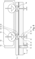
- Fig. 1 schematically shows an example of an aircraft floor arrangement 10 with customizable load-bearing capabilities.
- the aircraft floor arrangement 10 comprises a plurality of floor panels 12 and at least one support profile 14.
- the at least one support profile 14 is configured to reinforce at least one of the floor panels 12 such that the load-bearing capabilities are increased.
- the floor panels 12 are provided with a plurality of interface points 16 arranged at least along one direction.
- the interface points 16 are configured for mounting of one of the support profiles 14 to one of the floor panels 12 via the interface points 16 to reinforce the floor panels 12.
- the at least one support profile 14 is shown with a plurality of interface connection points 18, e.g. complementary to the interface points 16.
- the interface connection points 18 are provided matching with a pattern or pitch of the interface points 16 of the floor panel 12 at least in that some are at matching locations to allow mounting the support profile 14 to the floor panels 12.
- the same pattern is provided for the plurality of interface connection points 18 as for the interface points 16.
- a multiple of the pattern is provided for the plurality of interface connection points 18 as for the interface points 16, or vice versa.
- the interface connection points 18 in a pitch two times of the pitch of the interface points 16, or three or more times the pitch, i.e. the repetitive distance between the points.
- An arrow 20 indicates the option of mounting the support profile 14 to the floor panel 12.
- the interface points 16 can also be referred to as interface location, interfaces, connection points, connection location, connector, mounting point or connecting interface.
- the interface points 16 are provided as connecting interfaces for additional mounting to the floor panel.
- the aircraft floor arrangement 10 is a cabin floor arrangement for a cabin area of an aircraft. In another option, the aircraft floor arrangement 10 is a cargo floor arrangement for a cargo area of an aircraft.
- the interface points are provided in a linear pattern, i.e. a one-dimensional pattern.
- the interface points are provided in a plane pattern, i.e. a two-dimensional pattern.
- a grid-like pattern is provided, e.g. with different or same pitches in two or more different directions.
- the load-bearing capabilities can be adapted.
- the support profiles 14 can be provided aligned to a longitudinal direction of the aircraft, i.e. in X-direction.
- the support profiles 14 can also be provided aligned to a direction transverse to the longitudinal direction of the aircraft, i.e. in Y-direction.
- the interface points 16 are provided in a grid pattern.
- the interface points 16 are provided as holes. In another example, the interface points 16 are provided as blind bushings or blind sockets.
- the support profile 14 is configured for reinforcing the floor panel 12 on at least one of the group of: i) below, ii) above; and iii) lateral.
- a plurality of different support profiles 14 is provided forming a reinforcement kit, the support profiles 14 being provided as at least one of the group of:
- Fig. 2 schematically shows an example of a floor system 100 for an aircraft.
- the floor system 100 comprises an example of the aircraft floor arrangement 10 according to one of the examples above.
- the floor system 100 further comprises a support arrangement 102 with a plurality of floor supports 104.
- the plurality of floor panels 12 of the aircraft floor arrangement 10 are carried by the floor supports 104.
- the floor panels 12 and the floor supports 104 are provided as part of the primary structure of the aircraft, i.e. the structure that is considered essential for the aircraft and that must not be changed or altered during use of the aircraft.
- the support profile/s 14 is/are not part of the primary structure and can be changed, e.g. installed, demounted or the like.
- the support arrangement 102 comprises a triangular cantilevering center console 106 attached to vertical floor supports 107 facing towards a center field and a further triangular cantilevering lateral console 108 facing towards a lateral side.
- the center consoles 106 provide the floor supports 104, and the lateral consoles 108 provide further supports 110 for lateral floor panels 112.
- a coordinate system is shown in Fig. 2 and the following figures, with an X-axis indicating the longitudinal direction of an aircraft, with a Y-axis indicating the horizontal direction transverse to the longitudinal direction of the aircraft and a Z-axis indicating the vertical direction transverse to the longitudinal direction and transvers to the horizontal transverse direction of the aircraft.
- Fig. 3 shows an example of an aircraft 200 in a cross-section.
- the aircraft 200 comprises a fuselage 202, a wing arrangement 204 attached to the fuselage 202, and a propulsion arrangement 206 attached to at least one of the group of the fuselage 202 and the wing arrangement 204.
- a floor 208 is provided in the fuselage 202 for a cabin or cargo area.
- the floor 208 comprises at least one example of the aircraft floor arrangement 10 according to one of the examples above and below, and an example of the floor system 100 for an aircraft cabin according to one of the examples above.
- support profile 14 is schematically shown.
- Fig. 4 shows basic steps of an example of a method 300 for customizing load-bearing capabilities of an aircraft floor arrangement.
- the method 300 comprises the following steps:
- Fig. 5 shows a cross section of an example of the floor panel 12 with an attached support profile 14.
- the fixation points 32 are provided for connecting the sheet-like structure 30 to the top layer 24 and the bottom layer 26.
- the fixation points 32 are provided as same points for top and bottom situation.
- the fixation points 32 are provided as different points for top and bottom situation, as shown in Fig. 5 .
- the lower of the fixation points 32 are provided as connectors 36 for connection to the support profile 14.
- the support profile 14 is provided as a profile vertically extending over the height of the floor panel 12.
- a first bracket indicates the floor panel 12 and a second bracket 40 indicates the support profile 14.
- the top layer 24 is the side of the floor panel 12 that faces towards the cabin or cargo area in a mounted state.
- the bottom layer 26 is the side of the floor panel 12 that faces away from the cabin or cargo area in the mounted state.
- the sheet-like structure 30 is provided as at least one of the group comprising: a corrugated sheet, a trapezoidal sheet, a troughed sheet and a profiled sheet.
- the support profile 14 is provided as an integratable profile 41 comprising horizontal flange portions for mounting adjacent floor panels and vertical web members providing additional load support.
- the support profile 14 comprises the upper flange segment 54 configured to provide a local trolley support.
- a trolley 60 is indicated with its wheels 62.
- An arrow illustrates the weight force on the wheels 62 resting directly above the flange segment 54. Due to the local reinforcement, the additional weight forces can be compensated for.
- the floor panels 12 can be reinforced by the at least one support profile 14 to provide additional load carrying capabilities when required.
- Fig. 7 shows the example of Fig. 6 with a mount to a cross beam 68.
- a bracket 70 provides a connection to the support profile 14.
- Omega-shaped profiles 72 are provided for further support of the floor panels 12, e.g. also carrying a seat rail.
- Fig. 8 shows the example pf Fig. 7 in a transverse cross-section.
Landscapes
- Engineering & Computer Science (AREA)
- Mechanical Engineering (AREA)
- Aviation & Aerospace Engineering (AREA)
- Floor Finish (AREA)
- Body Structure For Vehicles (AREA)
- Rolling Contact Bearings (AREA)
Priority Applications (1)
| Application Number | Priority Date | Filing Date | Title |
|---|---|---|---|
| EP25153227.1A EP4520655A3 (de) | 2023-07-31 | 2023-07-31 | Flugzeugbodenanordnung mit anpassbaren lasttragekapazitäten |
Applications Claiming Priority (2)
| Application Number | Priority Date | Filing Date | Title |
|---|---|---|---|
| EP25153227.1A EP4520655A3 (de) | 2023-07-31 | 2023-07-31 | Flugzeugbodenanordnung mit anpassbaren lasttragekapazitäten |
| EP23188739.9A EP4501777A1 (de) | 2023-07-31 | 2023-07-31 | Flugzeugbodenanordnung mit anpassbaren lasttragekapazitäten |
Related Parent Applications (1)
| Application Number | Title | Priority Date | Filing Date |
|---|---|---|---|
| EP23188739.9A Division EP4501777A1 (de) | 2023-07-31 | 2023-07-31 | Flugzeugbodenanordnung mit anpassbaren lasttragekapazitäten |
Publications (2)
| Publication Number | Publication Date |
|---|---|
| EP4520655A2 true EP4520655A2 (de) | 2025-03-12 |
| EP4520655A3 EP4520655A3 (de) | 2025-04-02 |
Family
ID=87551208
Family Applications (2)
| Application Number | Title | Priority Date | Filing Date |
|---|---|---|---|
| EP23188739.9A Withdrawn EP4501777A1 (de) | 2023-07-31 | 2023-07-31 | Flugzeugbodenanordnung mit anpassbaren lasttragekapazitäten |
| EP25153227.1A Pending EP4520655A3 (de) | 2023-07-31 | 2023-07-31 | Flugzeugbodenanordnung mit anpassbaren lasttragekapazitäten |
Family Applications Before (1)
| Application Number | Title | Priority Date | Filing Date |
|---|---|---|---|
| EP23188739.9A Withdrawn EP4501777A1 (de) | 2023-07-31 | 2023-07-31 | Flugzeugbodenanordnung mit anpassbaren lasttragekapazitäten |
Country Status (3)
| Country | Link |
|---|---|
| US (1) | US20250042533A1 (de) |
| EP (2) | EP4501777A1 (de) |
| CN (1) | CN119429077A (de) |
Family Cites Families (8)
| Publication number | Priority date | Publication date | Assignee | Title |
|---|---|---|---|---|
| FR2891325B1 (fr) * | 2005-09-28 | 2007-10-26 | Airbus France Sas | Dispositif pour la fixation d'un panneau leger sur un support |
| DE102008041788A1 (de) * | 2008-09-03 | 2010-03-11 | Airbus Deutschland Gmbh | Sandwichplatte mit integrierter Verstärkungsstruktur sowie Verfahren zu deren Herstellung |
| BR112012000770B1 (pt) * | 2009-07-21 | 2019-11-19 | Telair Int Gmbh | elemento de piso para uma plataforma de carga de uma aeronave e uso de um elemento de piso |
| EP2818403B1 (de) * | 2013-06-24 | 2016-02-10 | Airbus Operations GmbH | Lokal verstärktes Flugzeugstrukturbauteil |
| DE102018122813B4 (de) * | 2018-09-18 | 2021-02-25 | Airbus Operations Gmbh | Fußbodensystem für ein Fahrzeug |
| US11518492B2 (en) * | 2019-01-28 | 2022-12-06 | Techno-Coatings, Inc. | Aircraft flooring architecture |
| WO2024004301A1 (ja) * | 2022-06-29 | 2024-01-04 | 新明和工業株式会社 | パネル部材、パネル部材の製造方法、およびパネル部材の製造装置 |
| EP4378822B1 (de) * | 2022-11-30 | 2025-12-31 | Airbus Operations GmbH | Bodensystem für eine kabine eines fahrzeugs |
-
2023
- 2023-07-31 EP EP23188739.9A patent/EP4501777A1/de not_active Withdrawn
- 2023-07-31 EP EP25153227.1A patent/EP4520655A3/de active Pending
-
2024
- 2024-07-29 US US18/787,441 patent/US20250042533A1/en active Pending
- 2024-07-29 CN CN202411021344.0A patent/CN119429077A/zh active Pending
Also Published As
| Publication number | Publication date |
|---|---|
| US20250042533A1 (en) | 2025-02-06 |
| CN119429077A (zh) | 2025-02-14 |
| EP4501777A1 (de) | 2025-02-05 |
| EP4520655A3 (de) | 2025-04-02 |
Similar Documents
| Publication | Publication Date | Title |
|---|---|---|
| EP2179920B1 (de) | Flugzeugkabinenbodenstrukturen, Systeme und Verfahren | |
| US8360363B2 (en) | Floor structure in an aircraft with continuous panels | |
| CN101421155B (zh) | 飞行器地板、该地板的应用以及装配有该地板的飞行器舱段 | |
| US8074928B2 (en) | Floor system for a fuselage airframe of an aircraft | |
| EP2018316B1 (de) | Bodenstruktur für rumpf | |
| US20180016010A1 (en) | Large self-carrying monument assembly for an aircraft and an aircraft having such a monument assembly | |
| US8967539B2 (en) | Method for assembling a floor in a cockpit structure previously constructed from a section of aircraft fuselage | |
| JP5246943B2 (ja) | フロアパネル、およびそのようなパネルを含むレイアウト部材の固定用設備 | |
| US20090236471A1 (en) | Non-Protruding Seat Track Apparatus and Methods | |
| CN102015442A (zh) | 航空器地板组件的固定方法 | |
| CN102271984A (zh) | 用于飞行器的模块化地板 | |
| US20250042533A1 (en) | Aircraft floor arrangement with customizable load-bearing capabilities | |
| EP3750792A1 (de) | Unterstruktur für standardkabinenmonument | |
| US12559223B2 (en) | Floor arrangement in an aircraft | |
| CN101213130A (zh) | 地板上座椅导轨的固定装置和装配有这种固定装置的飞行器 | |
| US12208902B2 (en) | Seat unit provided with a tubular seat-base structure | |
| EP4470909A1 (de) | Sitzschiene und sitzverbinder | |
| US12077274B2 (en) | Aircraft comprising at least one systems cabinet connected to a landing gear compartment by at least one sliding connection sliding in a longitudinal direction | |
| US20250145272A1 (en) | Configurable Aircraft Aisle Flooring System | |
| EP3702263A1 (de) | Flugzeugstruktur zur strömungsregelung |
Legal Events
| Date | Code | Title | Description |
|---|---|---|---|
| PUAI | Public reference made under article 153(3) epc to a published international application that has entered the european phase |
Free format text: ORIGINAL CODE: 0009012 |
|
| STAA | Information on the status of an ep patent application or granted ep patent |
Free format text: STATUS: THE APPLICATION HAS BEEN PUBLISHED |
|
| PUAL | Search report despatched |
Free format text: ORIGINAL CODE: 0009013 |
|
| AC | Divisional application: reference to earlier application |
Ref document number: 4501777 Country of ref document: EP Kind code of ref document: P |
|
| AK | Designated contracting states |
Kind code of ref document: A2 Designated state(s): AL AT BE BG CH CY CZ DE DK EE ES FI FR GB GR HR HU IE IS IT LI LT LU LV MC ME MK MT NL NO PL PT RO RS SE SI SK SM TR |
|
| AK | Designated contracting states |
Kind code of ref document: A3 Designated state(s): AL AT BE BG CH CY CZ DE DK EE ES FI FR GB GR HR HU IE IS IT LI LT LU LV MC ME MK MT NL NO PL PT RO RS SE SI SK SM TR |
|
| RIC1 | Information provided on ipc code assigned before grant |
Ipc: E04C 2/32 20060101ALI20250221BHEP Ipc: B64C 1/18 20060101AFI20250221BHEP |
|
| STAA | Information on the status of an ep patent application or granted ep patent |
Free format text: STATUS: REQUEST FOR EXAMINATION WAS MADE |
|
| 17P | Request for examination filed |
Effective date: 20250929 |
|
| STAA | Information on the status of an ep patent application or granted ep patent |
Free format text: STATUS: EXAMINATION IS IN PROGRESS |
|
| 17Q | First examination report despatched |
Effective date: 20260216 |