EP4520631A1 - Rack guide - Google Patents
Rack guide Download PDFInfo
- Publication number
- EP4520631A1 EP4520631A1 EP23831136.9A EP23831136A EP4520631A1 EP 4520631 A1 EP4520631 A1 EP 4520631A1 EP 23831136 A EP23831136 A EP 23831136A EP 4520631 A1 EP4520631 A1 EP 4520631A1
- Authority
- EP
- European Patent Office
- Prior art keywords
- lubricant
- rack
- rack guide
- rack bar
- lubricant retaining
- Prior art date
- Legal status (The legal status is an assumption and is not a legal conclusion. Google has not performed a legal analysis and makes no representation as to the accuracy of the status listed.)
- Pending
Links
Images


Classifications
-
- B—PERFORMING OPERATIONS; TRANSPORTING
- B62—LAND VEHICLES FOR TRAVELLING OTHERWISE THAN ON RAILS
- B62D—MOTOR VEHICLES; TRAILERS
- B62D3/00—Steering gears
- B62D3/02—Steering gears mechanical
- B62D3/12—Steering gears mechanical of rack-and-pinion type
- B62D3/126—Steering gears mechanical of rack-and-pinion type characterised by the rack
-
- B—PERFORMING OPERATIONS; TRANSPORTING
- B62—LAND VEHICLES FOR TRAVELLING OTHERWISE THAN ON RAILS
- B62D—MOTOR VEHICLES; TRAILERS
- B62D3/00—Steering gears
- B62D3/02—Steering gears mechanical
- B62D3/12—Steering gears mechanical of rack-and-pinion type
- B62D3/123—Steering gears mechanical of rack-and-pinion type characterised by pressure yokes
-
- F—MECHANICAL ENGINEERING; LIGHTING; HEATING; WEAPONS; BLASTING
- F16—ENGINEERING ELEMENTS AND UNITS; GENERAL MEASURES FOR PRODUCING AND MAINTAINING EFFECTIVE FUNCTIONING OF MACHINES OR INSTALLATIONS; THERMAL INSULATION IN GENERAL
- F16H—GEARING
- F16H19/00—Gearings comprising essentially only toothed gears or friction members and not capable of conveying indefinitely-continuing rotary motion
- F16H19/02—Gearings comprising essentially only toothed gears or friction members and not capable of conveying indefinitely-continuing rotary motion for interconverting rotary or oscillating motion and reciprocating motion
- F16H19/04—Gearings comprising essentially only toothed gears or friction members and not capable of conveying indefinitely-continuing rotary motion for interconverting rotary or oscillating motion and reciprocating motion comprising a rack
Definitions
- the present invention relates to a rack guide for a steering device for changing a steering angle of a tire, and particularly to a rack guide for guiding a rack bar in a bar longitudinal direction.
- a rack guide for guiding a rack bar in a longitudinal direction
- a rack guide comprising a multilayer sliding piece having: a pair of inclined surface portions facing each other; a pair of flat surface portions continuous with these corresponding inclined surface portions; a bottom surface portion continuous with each of the flat surface portions; and a hollow protrusion portion extending at the center of this bottom surface portion toward a backing metal side, the multilayer sliding piece being configured to support the rack bar (for example, see Patent Literature 1).
- Patent Literature 1 JP2006-116994A (particularly, see fig. 2 .)
- Recessed portions in the inclined surface portions of the multilayer sliding piece of the rack guide as described above are filled with a lubricant, and when the rack bar moves in the rack bar longitudinal direction, the lubricant filling the recessed portions is supplied to the rack bar, whereas it is possible that the lubricant is insufficiently fed to the recessed portions so that the lubricant is drained from the recessed portions.
- the present invention is to solve the problem of conventional technologies as described above and it is an object of the present invention to provide a rack guide which achieves both a stable feed of a lubricant from a rack bar to a lubricant retaining groove and a stable supply of the lubricant from the lubricant retaining groove to the rack bar when the rack bar slides against the rack guide.
- the invention according to claim 1 is to solve the above problem by a rack guide for a steering device, comprising a supporting surface for supporting a sliding surface provided behind a meshing surface formed on a rack bar having a D-shaped cross section, the rack bar being configured to mesh with a pinion formed on a steering shaft to convert a rotational motion of the steering shaft into a linear motion, the rack guide being configured to guide the rack bar in a bar longitudinal direction of the rack bar to change a steering angle of a tire, in which the sliding surface of the rack bar is a curved surface formed to have a single radius of curvature, the supporting surface is a curved surface having a contact area configured to come into slidable contact with the rack bar and a spaced facing area configured to face the rack bar with a space therebetween, the contact area is located between the spaced facing area on an inner side closer to a rack guide longitudinal center axis configured to extend in a rack guide longitudinal direction parallel to a sliding direction of the rack bar and the spaced facing area on an outer side farther
- the invention according to claim 2 is to further solve the above problem by, in addition to the configuration of the invention according to claim 1, a feature in which the lubricant retaining groove is formed to be deeper in accordance with bulging of the lubricant retaining groove.
- the invention according to claim 3 is to further solve the above problem by, in addition to the configuration of the invention according to claim 1 or claim 2 , a feature in which the lubricant retaining groove is formed by a straight portion perpendicular to the contact area of the supporting surface, the contact area extending in the rack guide longitudinal direction, and a bulge portion passing both ends of the straight portion and the apex.
- the invention according to claim 4 is to further solve the above problem by, in addition to the configuration of the invention according to claim 1 or claim 2 , a feature in which the pair of lubricant retaining grooves are formed to be line-symmetrical, and groove depths of the pair of lubricant retaining grooves are equal to each other.
- At least one pair of lubricant retaining grooves configured to retain a lubricant interposed between the rack bar and the supporting surface and face each other in the rack guide longitudinal direction extend in a rack guide transverse direction perpendicular to the rack guide longitudinal direction and are arranged on the supporting surface in such a shape as to bulge away from each other in the rack guide longitudinal direction, and an apex of each of the lubricant retaining grooves in the rack guide longitudinal direction is located in the contact area, whereby, while the rack bar slides in the bar longitudinal direction, even when the lubricant retained near the apex of the lubricant retaining groove is dragged by the lubricant adhering to the rack bar so as to flow out from the lubricant retaining groove to the exterior of the lubricant retaining groove, in accordance with such outflow of the lubricant near the apex of the lubricant retaining groove, the lubricant in the spaced facing area
- the lubricant retaining groove is formed to be deeper in accordance with bulging of the lubricant retaining groove, which makes it easier for the lubricant to accumulate at an outer end side of the lubricant retaining groove with a great groove depth and makes it easier for the lubricant to flow out of an inner end side of the lubricant retaining groove with a shallow groove depth, and when the rack bar slides to the outer end side of the lubricant retaining groove, in accordance with outflow of the lubricant from the outer end side of the lubricant retaining groove due to sliding of the rack bar, the lubricant in the spaced facing area on the inner side and in the spaced facing area on the outer side flows into the lubricant retaining groove and is retained at the outer end side of the lubricant retaining groove, so that when the rack bar slides to the inner end side of the lubricant retaining groove,
- the lubricant retaining groove is formed by a straight portion perpendicular to the contact area of the supporting surface, the contact area extending in the rack guide longitudinal direction, and a bulge portion passing both ends of the straight portion and the apex, which makes it easier for the lubricant retained near the straight portion of the lubricant retaining groove to adhere to the rack bar rather than flowing in the rack guide transverse direction when the rack bar slides toward a straight portion side of the lubricant retaining groove, so that when the rack bar slides against the rack guide, the lubricant can be stably supplied from the lubricant retaining groove to the rack bar, which can consequently make it easier to achieve both a stable feed of the lubricant from the rack bar to the lubricant retaining groove and a stable supply of the lubricant from the lubricant retaining groove to the rack bar.
- the pair of lubricant retaining grooves are formed to be line-symmetrical, and groove depths of the pair of lubricant retaining grooves are equal to each other, so that an inflow amount of the lubricant into the pair of lubricant retaining grooves and an outflow amount of the lubricant out of the pair of lubricant retaining grooves balance with each other, which can make it easier to keep constant a total amount of the lubricant retained by the rack guide.
- a rack guide for a steering device comprises a supporting surface for supporting a sliding surface provided behind a meshing surface formed on a rack bar having a D-shaped cross section, the rack bar being configured to mesh with a pinion formed on a steering shaft to convert a rotational motion of the steering shaft into a linear motion, the rack guide being configured to guide the rack bar in a bar longitudinal direction of the rack bar to change a steering angle of a tire, in which the sliding surface of the rack bar is a curved surface formed to have a single radius of curvature, the supporting surface is a curved surface having a contact area configured to come into slidable contact with the rack bar and a spaced facing area configured to face the rack bar with a space therebetween, the contact area is located between the spaced facing area on an inner side closer to a rack guide longitudinal center axis configured to extend in a rack guide longitudinal direction parallel to a sliding direction of the rack bar and the spaced facing area on an outer side farther from the rack
- the rack guide according to the present invention is configured to be mounted in a rack and pinion steering device of a four-wheeled vehicle, and then the four-wheeled vehicle may be not only a gasoline vehicle or a diesel vehicle but also an electric vehicle or the like.
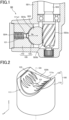
- fig. 1 is a cross-sectional view of a rack and pinion steering device in which a rack guide according to an embodiment of the present invention is installed.
- the rack guide 100 is configured to be mounted in a rack and pinion steering device SD of a four-wheeled vehicle.
- This rack and pinion steering device SD is configured to change a steering angle of tires (unillustrated) and includes a device housing SD1, a steering shaft SD2 configured to rotate integrally with a steering wheel, a rack bar SD3 configured to mesh with this steering shaft SD2 to convert a rotational motion of the steering shaft SD2 into a linear motion, a rack guide 100 configured to guide this rack bar SD3 in a bar longitudinal direction of the rack bar SD3, and a biasing spring SD4 configured to press this rack guide 100 against the rack bar SD3.
- a tip of the steering shaft SD2 is provided with a pinion SD2a configured to mesh with the rack bar SD3 which thus rotates integrally with the steering shaft SD2.
- the rack bar SD3 has a sliding surface SD3a which is a curved surface formed to have a single radius of curvature Rb and a meshing surface SD3b which is provided behind this sliding surface SD3a to serve as rack teeth configured to mesh with the steering shaft SD2, and thus the rack bar SD3 has a D-shaped cross section.
- the biasing spring SD4 is interposed between the device housing SD1 and the rack guide 100.
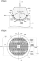
- Fig. 2 is a perspective view of the rack guide illustrated in fig. 1
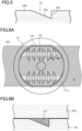
- fig. 3 is a side view illustrating a positional relationship between the rack guide and a rack bar illustrated in fig. 1
- fig. 4 is a plan view of the rack guide as seen from the IV direction in fig. 3
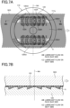
- fig. 5 is an end view of a lubricant retaining groove in the V-V cross section in fig. 4 .
- the rack guide 100 is provided with a rack guide body 110 and a seat 120.
- the rack guide body 110 is a cylindrical member made of a metal.
- this rack guide body 110 there is formed a seat placement groove 111 configured to extend in a seat placement groove longitudinal direction (x direction in fig. 2 ) perpendicular to a direction in which a longitudinal center axis of the rack guide body 110 (rack guide center axis GA) extends (z direction in fig. 2 ).
- a cross-sectional shape of this seat placement groove 111 is semicircular.
- a facing surface 111a of the seat placement groove 111 which faces the sliding surface SD3a of the rack bar SD3 is provided with a seat engagement hole 111a1 configured to engage with a convex portion 121 of the seat 120.
- the seat 120 is a member made of a resin having an excellent self-lubricating property (for example, a fluororesin, such as PTFE, a nylon resin or a polyacetal resin, such as POM) and has a substantially uniform thickness as illustrated in fig. 3 .
- a resin having an excellent self-lubricating property for example, a fluororesin, such as PTFE, a nylon resin or a polyacetal resin, such as POM
- the seat 120 has the convex portion 121 formed at the center in a plan view and configured to protrude toward the rack guide body 110.
- the seat 120 is integrated with the rack guide body 110 by inserting the convex portion 121 into the seat engagement hole 111a1 of the rack guide body 110 and allowing the same to engage therewith.
- the facing surface 111a of the rack guide body 110 which faces the sliding surface SD3a of the rack bar SD3 is arranged at a position farther away from the rack bar SD3 than a supporting surface 120A of the seat 120 which supports the sliding surface SD3a of the rack bar SD3 as illustrated in fig. 3 .
- the supporting surface 120A of the seat 120 is symmetrical with respect to a seat longitudinal center axis LA configured to pass through the center of the convex portion 121 and extend in a seat longitudinal direction (X direction in fig. 4 ) and also with respect to a seat transverse center axis WA configured to pass through the center of the convex portion 121 and extend in a seat transverse direction (Y direction in fig. 4 ).
- the seat longitudinal center axis LA and the seat transverse center axis WA are perpendicular to the rack guide center axis GA.
- the seat longitudinal direction of the seat 120 is the same direction as the seat placement groove longitudinal direction of the rack guide body 110 and the longitudinal direction (sliding direction) of the rack bar SD3, and the seat longitudinal center axis LA is coaxial with the rack guide longitudinal center axis.
- the seat transverse direction of the seat 120 is perpendicular to the seat longitudinal direction of the seat 120, and the seat transverse center axis WA is coaxial with a rack guide transverse center axis.
- the supporting surface 120A has two centers of curvature Os1, Os2.
- these centers of curvature Os1, Os2 are arranged with the rack guide center axis GA therebetween in the Y direction, while being arranged at approximately the same position in the z direction.
- a radius of curvature about the center of curvature Os1 and a radius of curvature about the center of curvature Os2 are the same radius of curvature Rs.
- the supporting surface 120A is formed not by a single curved surface, such as the sliding surface SD3a of the rack bar SD3, but by two curved surfaces combined together.
- the supporting surface 120A has a contact area 120A1 configured to come into slidable contact with the rack bar SD3 and a spaced facing area 120A2 configured to face the rack bar SD3 with a space therebetween as illustrated in fig. 3 and fig. 4 .
- the supporting surface 120A of the seat 120 is provided with a plurality of lubricant retaining grooves 122 interposed between the sliding surface SD3a of the rack bar SD3 and the supporting surface 120A of the seat 120 to retain a lubricant for allowing the rack bar SD3 to smoothly slide against the seat 120.
- these lubricant retaining grooves 122 are arranged in the supporting surface 120A in such a manner as to be symmetrical with respect to the seat longitudinal center axis LA and the seat transverse center axis WA.
- the lubricant retaining grooves 122 form a pair in the seat longitudinal direction (about the seat transverse center axis WA), and the pair of lubricant retaining grooves 122 are formed to be line-symmetrical with respect to the seat transverse center axis WA.
- each of the lubricant retaining grooves 122 is configured to extend in the seat transverse direction (rack guide transverse direction), while bulging in the seat longitudinal direction (rack guide longitudinal direction) and in a direction farther away from the seat transverse center axis WA.
- each of the lubricant retaining grooves 122 arranged line-symmetrically with respect to the seat transverse center axis WA bulge in a direction farther away from each other, and each of the lubricant retaining grooves 122 is formed by a straight portion 122A extending in a direction perpendicular to the contact area 120A1 extending in the seat longitudinal direction (i.e., the seat transverse direction) and a bulge portion 122B bulging from both ends of this straight portion 122A.
- an apex 122B1 of this bulge portion 122B in the seat longitudinal direction is located in the contact area 120A1.
- a cross-sectional shape of this lubricant retaining groove 122 is illustrated in fig. 5 , and the lubricant retaining groove 122 is formed by a vertical wall surface 122a which forms the bulge portion 122B and an inclined surface 122b which connects this vertical wall surface 122a and the supporting surface 120A with each other.
- the straight portion 122A is a boundary between the inclined surface 122b and the supporting surface 120A.
- the vertical wall surface 122a extends in a thickness direction of the seat 120 and has a height maximum near the apex and minimum near both ends of the straight portion 122A as illustrated in fig. 2 .
- the lubricant retaining groove 122 is formed to be deeper in accordance with bulging of the lubricant retaining groove 122. That is to say, in the seat longitudinal direction, an outer end side (bulge portion 122B) of the lubricant retaining groove 122 farther away from the seat transverse center axis WA is formed to be deeper than an inner end side (straight portion 122A) of the lubricant retaining groove closer to the seat transverse center axis WA.
- groove depths of the pair of lubricant retaining grooves 122 arranged line-symmetrically with respect to the seat transverse center axis WA are equal to each other.
- Fig. 6A is a plan view illustrating a positional relationship of the rack guide and the rack bar illustrated in fig. 1 and the lubricant
- fig. 6B is an end view of the lubricant retaining groove in the VIB-VIB cross section of fig. 6A
- fig. 7A is a plan view illustrating a flow of the lubricant when the rack bar is moved to the right of the page
- fig. 7B is an end view of the lubricant retaining groove in the VIIB-VIIB cross section of fig. 7A
- fig. 8A is a plan view illustrating a flow of the lubricant when the rack bar is moved to the left of the page
- fig. 8B is an end view of the lubricant retaining groove in the VIIIB-VIIIB cross section of fig. 8A .
- the lubricant G is applied to the rack bar SD3, so that when the rack bar SD3 slides against the rack guide 100, the lubricant G is interposed between the rack bar SD3 and the rack guide 100 as illustrated in fig. 6A and fig. 6B .
- the lubricant G on the seat 120 side also starts to flow due to the viscosity of the lubricant G.
- the lubricant G on the seat 120 side in an area in which the lubricant retaining groove 122 of the seat 120 is not provided flows to the right side of the page, i.e., toward the lubricant retaining groove 122 and flows from the straight portion 122A of the lubricant retaining groove 122 into the interior of the lubricant retaining groove 122.
- the lubricant G retained in the spaced facing area 120A2 of the lubricant retaining groove 122 is drawn into the direction of low flow resistance, i.e., toward the contact area 120A1 rather than climbing over the vertical wall surface 122a, so that the lubricant G is retained most near the apex 122B1 in the lubricant retaining groove 122.
- the lubricant G retained in the lubricant retaining groove 122 adheres to the rack bar SD3 most in the contact area 120A1, i.e., most near the apex 122B1 in the lubricant retaining groove 122.
- the lubricant G retained in the lubricant retaining groove 122 flows out to the right side of the page, i.e., from the straight portion 122A of the lubricant retaining groove 122 to the exterior of the lubricant retaining groove 122.
- the lubricant G on the seat 120 side also starts to flow due to the viscosity of the lubricant G, and then the seat 120 is configured to be symmetrical with respect to the seat transverse center axis WA, so that the behavior of the lubricant G on the rack bar SD3 side and the lubricant G on the seat 120 side is exactly the same as that when the rack bar SD3 moves to the right of the page as illustrated in fig. 7A and fig. 7B , while the direction of movement of the rack bar SD3 is different.
- a pair of lubricant retaining grooves 122 configured to retain the lubricant G interposed between the rack bar SD3 and the supporting surface 120A and face each other in the rack guide longitudinal direction extend in the seat transverse direction (rack guide transverse direction) perpendicular to the seat longitudinal direction (rack guide longitudinal direction) and are arranged on the supporting surface 120A in such a shape as to bulge away from each other in the seat guide longitudinal direction, and the apex 122B1 of each of the lubricant retaining grooves 122 in the seat longitudinal direction is located in the contact area 120A1, whereby, while the sliding surface SD3a of the rack bar SD3 slides in the bar longitudinal direction, even when the lubricant G retained near the apex 122B1 of the lubricant retaining groove 122 is dragged by the lubricant G adhering to the rack bar SD3 so as to flow out from the lubricant retaining groove 122 to the exterior of the lub
- the lubricant G adhering to the sliding surface SD3a of the rack bar SD3 is evenly used, which can extend the lifetime of the rack guide 100.
- the lubricant retaining groove 122 is arranged in all the contact area 120A1 of the supporting surface 120A, whereby the lubricant can be evenly supplied to the rack bar SD3.
- a groove depth of each of a pair of lubricant retaining grooves 122 becomes greater toward a direction in which each of the lubricant retaining grooves 122 bulges, which makes it easier for the lubricant G to accumulate at an outer end side of the lubricant retaining groove 122 with a great groove depth and makes it easier for the lubricant G to flow out of an inner end side of the lubricant retaining groove 122 with a shallow groove depth, and when the rack bar SD3 slides to the outer end side of the lubricant retaining groove 122, in accordance with outflow of the lubricant G from the outer end side of the lubricant retaining groove 122 due to sliding of the rack bar SD3, the lubricant G in the spaced facing area 120A2i on the inner side and in the spaced facing area 120A2o on the outer side flows into the lubricant retaining groove 122 and is retained at the outer end side of the lubricant retaining groove 122, so that when the rack bar
- the lubricant retaining groove 122 is formed by the straight portion 122A perpendicular to the contact area 120A1 of the supporting surface 120A, the contact area extending in the seat longitudinal direction, and the bulge portion 122B passing both ends of this straight portion 122A and the apex 122B1, which makes it easier for the lubricant G retained near the straight portion 122A of the lubricant retaining groove 122 to adhere to the rack bar SD3 rather than flowing in the seat transverse direction when the rack bar SD3 slides toward a straight portion 122A side of the lubricant retaining groove 122, so that when the rack bar SD3 slides against the rack guide 100, the lubricant G can be stably supplied from the lubricant retaining groove 122 to the rack bar SD3, which can consequently make it easier to achieve both a stable feed of the lubricant G from the rack bar SD3 to the lubricant retaining groove 122 and a stable supply of the lubricant G from the lubricant
- the rack guide according to an embodiment of the present invention has been described above, but the rack guide according to the present invention is not limited to the rack guide according to the above embodiment.
- the rack guide body 110 is made of a metal, but the material of the rack guide body is not limited to a metal, and the rack guide body may be made of, for example, a resin.
- the seat 120 has a uniform thickness, but the seat thickness may be non-uniform.
- the number of lubricant retaining grooves 122 in the seat 120 is eight, but the number of lubricant retaining grooves arranged in the seat is not limited to eight as long as the lubricant retaining grooves are arranged symmetrically with respect to the seat longitudinal center axis LA and the seat transverse center axis WA.
- the rack guide 100 is made from two members, i.e., the rack guide body 110 and the seat 120, but the rack guide body and the seat may be integrally formed.
- the pair of lubricant retaining grooves 122 are positionally aligned in the seat transverse direction, but the pair of lubricant retaining grooves is not limited to this configuration as long as the lubricant retaining grooves form a pair in the rack guide longitudinal direction, and the pair of lubricant retaining grooves may be offset, for example, in the seat transverse direction.
- the lubricant retaining groove 122 formed in the seat 120 is formed by the straight portion 122A and the arc-shaped bulge portion 122B as illustrated in fig. 4 , but the shape of the lubricant retaining groove is not limited to the above embodiment as long as the lubricant retaining groove bulges in the rack guide longitudinal direction and has an apex located in the contact area, and the lubricant retaining groove may have a shape, for example, as illustrated in fig. 9A to fig. 9C .
- a lubricant retaining groove 222 may be formed by a straight portion 222A and a broken line bulge portion 222B, similarly to a rack guide 300 as illustrated in fig. 9B which is a plan view of a rack guide according to a second variant of the present invention, a lubricant retaining groove 322 may be formed by two arc-shaped bulge portions or similarly to a rack guide 400 as illustrated in fig. 9C which is a plan view of a rack guide according to a third variant of the present invention, a lubricant retaining groove 422 may be formed to have a diamond shape.
- the pair of lubricant retaining grooves 122 formed in seat 120 are arranged about the seat transverse center axis WA, but the pair of lubricant retaining grooves according to the present invention are not limited to this configuration as long as the lubricant retaining grooves form a pair in the rack guide longitudinal direction.
- a pair of lubricant retaining grooves 522 may be formed about an axis of symmetry A parallel to the seat transverse center axis WA.
Landscapes
- Engineering & Computer Science (AREA)
- General Engineering & Computer Science (AREA)
- Mechanical Engineering (AREA)
- Chemical & Material Sciences (AREA)
- Combustion & Propulsion (AREA)
- Transportation (AREA)
- Transmission Devices (AREA)
- Bearings For Parts Moving Linearly (AREA)
Abstract
Description
- The present invention relates to a rack guide for a steering device for changing a steering angle of a tire, and particularly to a rack guide for guiding a rack bar in a bar longitudinal direction.
- Conventionally, as a rack guide for guiding a rack bar in a longitudinal direction, there is known a rack guide comprising a multilayer sliding piece having: a pair of inclined surface portions facing each other; a pair of flat surface portions continuous with these corresponding inclined surface portions; a bottom surface portion continuous with each of the flat surface portions; and a hollow protrusion portion extending at the center of this bottom surface portion toward a backing metal side, the multilayer sliding piece being configured to support the rack bar (for example, see Patent Literature 1).
- Patent Literature 1:
JP2006-116994A fig. 2 .) - Recessed portions in the inclined surface portions of the multilayer sliding piece of the rack guide as described above are filled with a lubricant, and when the rack bar moves in the rack bar longitudinal direction, the lubricant filling the recessed portions is supplied to the rack bar, whereas it is possible that the lubricant is insufficiently fed to the recessed portions so that the lubricant is drained from the recessed portions.
- Thus, the present invention is to solve the problem of conventional technologies as described above and it is an object of the present invention to provide a rack guide which achieves both a stable feed of a lubricant from a rack bar to a lubricant retaining groove and a stable supply of the lubricant from the lubricant retaining groove to the rack bar when the rack bar slides against the rack guide.
- The invention according to claim 1 is to solve the above problem by a rack guide for a steering device, comprising a supporting surface for supporting a sliding surface provided behind a meshing surface formed on a rack bar having a D-shaped cross section, the rack bar being configured to mesh with a pinion formed on a steering shaft to convert a rotational motion of the steering shaft into a linear motion, the rack guide being configured to guide the rack bar in a bar longitudinal direction of the rack bar to change a steering angle of a tire, in which the sliding surface of the rack bar is a curved surface formed to have a single radius of curvature, the supporting surface is a curved surface having a contact area configured to come into slidable contact with the rack bar and a spaced facing area configured to face the rack bar with a space therebetween, the contact area is located between the spaced facing area on an inner side closer to a rack guide longitudinal center axis configured to extend in a rack guide longitudinal direction parallel to a sliding direction of the rack bar and the spaced facing area on an outer side farther from the rack guide longitudinal center axis, and at least one pair of lubricant retaining grooves configured to retain a lubricant interposed between the rack bar and the supporting surface and face each other in the rack guide longitudinal direction extend in a rack guide transverse direction perpendicular to the rack guide longitudinal direction and are arranged on the supporting surface in such a shape as to bulge away from each other in the rack guide longitudinal direction, and an apex of each of the lubricant retaining grooves in the rack guide longitudinal direction is located in the contact area.
- The invention according to claim 2 is to further solve the above problem by, in addition to the configuration of the invention according to claim 1, a feature in which the lubricant retaining groove is formed to be deeper in accordance with bulging of the lubricant retaining groove.
- The invention according to claim 3 is to further solve the above problem by, in addition to the configuration of the invention according to claim 1 or claim 2, a feature in which the lubricant retaining groove is formed by a straight portion perpendicular to the contact area of the supporting surface, the contact area extending in the rack guide longitudinal direction, and a bulge portion passing both ends of the straight portion and the apex.
- The invention according to claim 4 is to further solve the above problem by, in addition to the configuration of the invention according to claim 1 or claim 2, a feature in which the pair of lubricant retaining grooves are formed to be line-symmetrical, and groove depths of the pair of lubricant retaining grooves are equal to each other.
- According to the rack guide of the invention according to claim 1, at least one pair of lubricant retaining grooves configured to retain a lubricant interposed between the rack bar and the supporting surface and face each other in the rack guide longitudinal direction extend in a rack guide transverse direction perpendicular to the rack guide longitudinal direction and are arranged on the supporting surface in such a shape as to bulge away from each other in the rack guide longitudinal direction, and an apex of each of the lubricant retaining grooves in the rack guide longitudinal direction is located in the contact area, whereby, while the rack bar slides in the bar longitudinal direction, even when the lubricant retained near the apex of the lubricant retaining groove is dragged by the lubricant adhering to the rack bar so as to flow out from the lubricant retaining groove to the exterior of the lubricant retaining groove, in accordance with such outflow of the lubricant near the apex of the lubricant retaining groove, the lubricant in the spaced facing area on the inner side and in the spaced facing area on the outer side is drawn toward the vicinity of the apex of the lubricant retaining groove and the lubricant flows from at least one of the supporting surface and the rack bar into the lubricant retaining groove and is thus fed thereinto, which can achieve both a stable feed of the lubricant from the rack bar to the lubricant retaining groove and a stable supply of the lubricant from the lubricant retaining groove to the rack bar.
- According to the rack guide of the invention according to claim 2, in addition to the effects produced by the rack guide of the invention according to claim 1, the lubricant retaining groove is formed to be deeper in accordance with bulging of the lubricant retaining groove, which makes it easier for the lubricant to accumulate at an outer end side of the lubricant retaining groove with a great groove depth and makes it easier for the lubricant to flow out of an inner end side of the lubricant retaining groove with a shallow groove depth, and when the rack bar slides to the outer end side of the lubricant retaining groove, in accordance with outflow of the lubricant from the outer end side of the lubricant retaining groove due to sliding of the rack bar, the lubricant in the spaced facing area on the inner side and in the spaced facing area on the outer side flows into the lubricant retaining groove and is retained at the outer end side of the lubricant retaining groove, so that when the rack bar slides to the inner end side of the lubricant retaining groove, in accordance with sliding of the rack bar, the lubricant retained near an inner end of the lubricant retaining groove flows so as to adhere to the rack bar, which can reliably achieve both a stable feed of the lubricant from the rack bar to the lubricant retaining groove and a stable supply of the lubricant from the lubricant retaining groove to the rack bar.
- According to the rack guide of the invention according to claim 3, in addition to the effects produced by the rack guide of the invention according to claim 1 or claim 2, the lubricant retaining groove is formed by a straight portion perpendicular to the contact area of the supporting surface, the contact area extending in the rack guide longitudinal direction, and a bulge portion passing both ends of the straight portion and the apex, which makes it easier for the lubricant retained near the straight portion of the lubricant retaining groove to adhere to the rack bar rather than flowing in the rack guide transverse direction when the rack bar slides toward a straight portion side of the lubricant retaining groove, so that when the rack bar slides against the rack guide, the lubricant can be stably supplied from the lubricant retaining groove to the rack bar, which can consequently make it easier to achieve both a stable feed of the lubricant from the rack bar to the lubricant retaining groove and a stable supply of the lubricant from the lubricant retaining groove to the rack bar.
- According to the rack guide of the invention according to claim 4 of the present invention, in addition to the effects produced by the rack guide of the invention according to claim 1 or claim 2, the pair of lubricant retaining grooves are formed to be line-symmetrical, and groove depths of the pair of lubricant retaining grooves are equal to each other, so that an inflow amount of the lubricant into the pair of lubricant retaining grooves and an outflow amount of the lubricant out of the pair of lubricant retaining grooves balance with each other, which can make it easier to keep constant a total amount of the lubricant retained by the rack guide.
-
-
Fig. 1 is a cross-sectional view of a rack and pinion steering device in which a rack guide according to an embodiment of the present invention is installed. -
Fig. 2 is a perspective view of the rack guide illustrated infig. 1 . -
Fig. 3 is a side view illustrating a positional relationship between the rack guide and a rack bar illustrated infig. 1 . -
Fig. 4 is a plan view of the rack guide as seen from the IV direction infig. 3 . -
Fig. 5 is an end view of a lubricant retaining groove in the V-V cross section infig. 4 . -
Fig. 6A is a plan view illustrating a positional relationship of the rack guide and the rack bar illustrated infig. 1 and the lubricant. -
Fig. 6B is an end view of the lubricant retaining groove in the VIB-VIB cross section offig. 6A . -
Fig. 7A is a plan view illustrating a flow of the lubricant when the rack bar is moved to the right of the page. -
Fig. 7B is an end view of the lubricant retaining groove in the VIIB-VIIB cross section offig. 7A . -
Fig. 8A is a plan view illustrating a flow of the lubricant when the rack bar is moved to the left of the page. -
Fig. 8B is an end view of the lubricant retaining groove in the VIIIB-VIIIB cross section offig. 8A . -
Fig. 9A is a plan view of a rack guide according to a first variant of the present invention. -
Fig. 9B is a plan view of a rack guide according to a second variant of the present invention. -
Fig. 9C is a plan view of a rack guide according to a third variant of the present invention. -
Fig. 9D is a plan view of a rack guide according to a fourth variant of the present invention. - Any specific embodiment of the present invention may be suitable as long as a rack guide for a steering device comprises a supporting surface for supporting a sliding surface provided behind a meshing surface formed on a rack bar having a D-shaped cross section, the rack bar being configured to mesh with a pinion formed on a steering shaft to convert a rotational motion of the steering shaft into a linear motion, the rack guide being configured to guide the rack bar in a bar longitudinal direction of the rack bar to change a steering angle of a tire, in which the sliding surface of the rack bar is a curved surface formed to have a single radius of curvature, the supporting surface is a curved surface having a contact area configured to come into slidable contact with the rack bar and a spaced facing area configured to face the rack bar with a space therebetween, the contact area is located between the spaced facing area on an inner side closer to a rack guide longitudinal center axis configured to extend in a rack guide longitudinal direction parallel to a sliding direction of the rack bar and the spaced facing area on an outer side farther from the rack guide longitudinal center axis, and at least one pair of lubricant retaining grooves configured to retain a lubricant interposed between the rack bar and the supporting surface and face each other in the rack guide longitudinal direction extend in a rack guide transverse direction perpendicular to the rack guide longitudinal direction and are arranged on the supporting surface in such a shape as to bulge away from each other in the rack guide longitudinal direction, and an apex of each of the lubricant retaining grooves in the rack guide longitudinal direction is located in the contact area, in which the rack guide achieves both a stable feed of the lubricant from the rack bar to the lubricant retaining groove and a stable supply of the lubricant from the lubricant retaining groove to the rack bar when the rack bar slides against the rack guide.
- For example, the rack guide according to the present invention is configured to be mounted in a rack and pinion steering device of a four-wheeled vehicle, and then the four-wheeled vehicle may be not only a gasoline vehicle or a diesel vehicle but also an electric vehicle or the like.
- Hereinafter, a
rack guide 100 according to an embodiment of the present invention will be explained with reference tofig. 1 to fig. 8B . - First, an environment in which the
rack guide 100 is mounted will be described with reference tofig. 1 which is a cross-sectional view of a rack and pinion steering device in which a rack guide according to an embodiment of the present invention is installed. - As illustrated in
fig. 1 , therack guide 100 according to the present embodiment is configured to be mounted in a rack and pinion steering device SD of a four-wheeled vehicle. - This rack and pinion steering device SD is configured to change a steering angle of tires (unillustrated) and includes a device housing SD1, a steering shaft SD2 configured to rotate integrally with a steering wheel, a rack bar SD3 configured to mesh with this steering shaft SD2 to convert a rotational motion of the steering shaft SD2 into a linear motion, a
rack guide 100 configured to guide this rack bar SD3 in a bar longitudinal direction of the rack bar SD3, and a biasing spring SD4 configured to press thisrack guide 100 against the rack bar SD3. - A tip of the steering shaft SD2 is provided with a pinion SD2a configured to mesh with the rack bar SD3 which thus rotates integrally with the steering shaft SD2.
- As illustrated in
fig. 1 , the rack bar SD3 has a sliding surface SD3a which is a curved surface formed to have a single radius of curvature Rb and a meshing surface SD3b which is provided behind this sliding surface SD3a to serve as rack teeth configured to mesh with the steering shaft SD2, and thus the rack bar SD3 has a D-shaped cross section. - The biasing spring SD4 is interposed between the device housing SD1 and the
rack guide 100. - Next, a structure of the
rack guide 100 will be described in detail with reference tofig. 1 to fig. 5 . -
Fig. 2 is a perspective view of the rack guide illustrated infig. 1 ,fig. 3 is a side view illustrating a positional relationship between the rack guide and a rack bar illustrated infig. 1 ,fig. 4 is a plan view of the rack guide as seen from the IV direction infig. 3 , andfig. 5 is an end view of a lubricant retaining groove in the V-V cross section infig. 4 . - As illustrated in
fig. 2 , etc., therack guide 100 is provided with arack guide body 110 and aseat 120. - As illustrated in
fig. 2 , therack guide body 110 is a cylindrical member made of a metal. - Then, on one end side of this
rack guide body 110, there is formed aseat placement groove 111 configured to extend in a seat placement groove longitudinal direction (x direction infig. 2 ) perpendicular to a direction in which a longitudinal center axis of the rack guide body 110 (rack guide center axis GA) extends (z direction infig. 2 ). - As illustrated in
fig. 1 andfig. 3 , a cross-sectional shape of thisseat placement groove 111 is semicircular. - Then, as illustrated in
fig. 1 , a facingsurface 111a of theseat placement groove 111 which faces the sliding surface SD3a of the rack bar SD3 is provided with a seat engagement hole 111a1 configured to engage with aconvex portion 121 of theseat 120. - The
seat 120 is a member made of a resin having an excellent self-lubricating property (for example, a fluororesin, such as PTFE, a nylon resin or a polyacetal resin, such as POM) and has a substantially uniform thickness as illustrated infig. 3 . - Then, as illustrated in
fig. 1 andfig. 4 , theseat 120 has theconvex portion 121 formed at the center in a plan view and configured to protrude toward therack guide body 110. - The
seat 120 is integrated with therack guide body 110 by inserting theconvex portion 121 into the seat engagement hole 111a1 of therack guide body 110 and allowing the same to engage therewith. - Thus, when the
seat 120 is assembled to therack guide body 110, the facingsurface 111a of therack guide body 110 which faces the sliding surface SD3a of the rack bar SD3 is arranged at a position farther away from the rack bar SD3 than a supportingsurface 120A of theseat 120 which supports the sliding surface SD3a of the rack bar SD3 as illustrated infig. 3 . - As illustrated in
fig. 4 , the supportingsurface 120A of theseat 120 is symmetrical with respect to a seat longitudinal center axis LA configured to pass through the center of theconvex portion 121 and extend in a seat longitudinal direction (X direction infig. 4 ) and also with respect to a seat transverse center axis WA configured to pass through the center of theconvex portion 121 and extend in a seat transverse direction (Y direction infig. 4 ). - In this case, the seat longitudinal center axis LA and the seat transverse center axis WA are perpendicular to the rack guide center axis GA.
- The seat longitudinal direction of the
seat 120 is the same direction as the seat placement groove longitudinal direction of therack guide body 110 and the longitudinal direction (sliding direction) of the rack bar SD3, and the seat longitudinal center axis LA is coaxial with the rack guide longitudinal center axis. - The seat transverse direction of the
seat 120 is perpendicular to the seat longitudinal direction of theseat 120, and the seat transverse center axis WA is coaxial with a rack guide transverse center axis. - Further, as illustrated in
fig. 3 , when theseat 120 is assembled to therack guide body 110, the supportingsurface 120A has two centers of curvature Os1, Os2. - As illustrated in
fig. 3 , these centers of curvature Os1, Os2 are arranged with the rack guide center axis GA therebetween in the Y direction, while being arranged at approximately the same position in the z direction. - Then, a radius of curvature about the center of curvature Os1 and a radius of curvature about the center of curvature Os2 are the same radius of curvature Rs.
- In other words, the supporting
surface 120A is formed not by a single curved surface, such as the sliding surface SD3a of the rack bar SD3, but by two curved surfaces combined together. - Note that on the rack guide center axis GA, a center of curvature Ob of the rack bar SD3 is located.
- Accordingly, when the
seat 120 is assembled to therack guide body 110, the supportingsurface 120A has a contact area 120A1 configured to come into slidable contact with the rack bar SD3 and a spaced facing area 120A2 configured to face the rack bar SD3 with a space therebetween as illustrated infig. 3 and fig. 4 . - As illustrated in
fig. 3 and fig. 4 , there are the two contact areas 120A1 with the seat longitudinal center axis LA therebetween, each of which is located between a spaced facing area 120A2i on the inner side (the side closer to the seat longitudinal center axis LA) and a spaced facing area 120A2o on the outer side (the side farther from the seat longitudinal center axis LA) in the rack guide transverse direction (Y direction). - As illustrated in
fig. 2 ,fig. 4 , etc., the supportingsurface 120A of theseat 120 is provided with a plurality oflubricant retaining grooves 122 interposed between the sliding surface SD3a of the rack bar SD3 and the supportingsurface 120A of theseat 120 to retain a lubricant for allowing the rack bar SD3 to smoothly slide against theseat 120. - As illustrated in
fig. 4 , theselubricant retaining grooves 122 are arranged in the supportingsurface 120A in such a manner as to be symmetrical with respect to the seat longitudinal center axis LA and the seat transverse center axis WA. - In other words, the
lubricant retaining grooves 122 form a pair in the seat longitudinal direction (about the seat transverse center axis WA), and the pair oflubricant retaining grooves 122 are formed to be line-symmetrical with respect to the seat transverse center axis WA. - Then, as illustrated in
fig. 4 , each of thelubricant retaining grooves 122 is configured to extend in the seat transverse direction (rack guide transverse direction), while bulging in the seat longitudinal direction (rack guide longitudinal direction) and in a direction farther away from the seat transverse center axis WA. - In other words, the pair of
lubricant retaining grooves 122 arranged line-symmetrically with respect to the seat transverse center axis WA bulge in a direction farther away from each other, and each of thelubricant retaining grooves 122 is formed by astraight portion 122A extending in a direction perpendicular to the contact area 120A1 extending in the seat longitudinal direction (i.e., the seat transverse direction) and abulge portion 122B bulging from both ends of thisstraight portion 122A. - Then, as illustrated in
fig. 4 , an apex 122B1 of thisbulge portion 122B in the seat longitudinal direction is located in the contact area 120A1. - A cross-sectional shape of this
lubricant retaining groove 122 is illustrated infig. 5 , and thelubricant retaining groove 122 is formed by avertical wall surface 122a which forms thebulge portion 122B and aninclined surface 122b which connects thisvertical wall surface 122a and the supportingsurface 120A with each other. - In other words, the
straight portion 122A is a boundary between theinclined surface 122b and the supportingsurface 120A. - The
vertical wall surface 122a extends in a thickness direction of theseat 120 and has a height maximum near the apex and minimum near both ends of thestraight portion 122A as illustrated infig. 2 . - In other words, the
lubricant retaining groove 122 is formed to be deeper in accordance with bulging of thelubricant retaining groove 122. That is to say, in the seat longitudinal direction, an outer end side (bulge portion 122B) of thelubricant retaining groove 122 farther away from the seat transverse center axis WA is formed to be deeper than an inner end side (straight portion 122A) of the lubricant retaining groove closer to the seat transverse center axis WA. - Thus, groove depths of the pair of
lubricant retaining grooves 122 arranged line-symmetrically with respect to the seat transverse center axis WA are equal to each other. - Next, a flow of a lubricant G interposed between the rack bar SD3 and the
rack guide 100 will be described with reference tofig. 6A to fig. 8B . -
Fig. 6A is a plan view illustrating a positional relationship of the rack guide and the rack bar illustrated infig. 1 and the lubricant,fig. 6B is an end view of the lubricant retaining groove in the VIB-VIB cross section offig. 6A ,fig. 7A is a plan view illustrating a flow of the lubricant when the rack bar is moved to the right of the page,fig. 7B is an end view of the lubricant retaining groove in the VIIB-VIIB cross section offig. 7A ,fig. 8A is a plan view illustrating a flow of the lubricant when the rack bar is moved to the left of the page, andfig. 8B is an end view of the lubricant retaining groove in the VIIIB-VIIIB cross section offig. 8A . - In the rack and pinion steering device SD as described above, the lubricant G is applied to the rack bar SD3, so that when the rack bar SD3 slides against the
rack guide 100, the lubricant G is interposed between the rack bar SD3 and therack guide 100 as illustrated infig. 6A and fig. 6B . - Then, as illustrated in
fig. 7A and fig. 7B , when the rack bar SD3 moves to the right of the page, the lubricant G adhering to the rack bar SD3 also moves to the right of the page in accordance with movement of the rack bar SD3 as indicated by gray arrows. - In accordance with such movement of the lubricant G, the lubricant G on the
seat 120 side also starts to flow due to the viscosity of the lubricant G. - First, a flow of the lubricant G around the
lubricant retaining groove 122 arranged on the right side of the page of the seat transverse center axis WA will be described. - As indicated by white arrows in
fig. 7A and fig. 7B , in accordance with movement of the lubricant G on the rack bar SD3 side, the lubricant G on theseat 120 side in an area in which thelubricant retaining groove 122 of theseat 120 is not provided flows to the right side of the page, i.e., toward thelubricant retaining groove 122 and flows from thestraight portion 122A of thelubricant retaining groove 122 into the interior of thelubricant retaining groove 122. - In accordance with such inflow of the lubricant G into the
lubricant retaining groove 122, the lubricant G adhering to the rack bar SD3 is also drawn toward thelubricant retaining groove 122. - As indicated by white arrows, the lubricant G retained in the spaced facing area 120A2 of the
lubricant retaining groove 122 is drawn into the direction of low flow resistance, i.e., toward the contact area 120A1 rather than climbing over thevertical wall surface 122a, so that the lubricant G is retained most near the apex 122B1 in thelubricant retaining groove 122. - Thus, in accordance with movement of the rack bar SD3, the lubricant G retained in the
lubricant retaining groove 122 adheres to the rack bar SD3 most in the contact area 120A1, i.e., most near the apex 122B1 in thelubricant retaining groove 122. - Next, a flow of the lubricant G around the
lubricant retaining groove 122 arranged on the left side of the page of the seat transverse center axis WA will be described. - As indicated by white arrows, in accordance with movement of the lubricant G on the rack bar SD3 side, the lubricant G retained in the
lubricant retaining groove 122 flows out to the right side of the page, i.e., from thestraight portion 122A of thelubricant retaining groove 122 to the exterior of thelubricant retaining groove 122. - Then, as illustrated in
fig. 8A and fig. 8B , when the rack bar SD3 moves to the left of the page, the lubricant G adhering to the rack bar SD3 also moves to the left of the page in accordance with movement of the rack bar SD3. - In accordance with such movement of the lubricant G, the lubricant G on the
seat 120 side also starts to flow due to the viscosity of the lubricant G, and then theseat 120 is configured to be symmetrical with respect to the seat transverse center axis WA, so that the behavior of the lubricant G on the rack bar SD3 side and the lubricant G on theseat 120 side is exactly the same as that when the rack bar SD3 moves to the right of the page as illustrated infig. 7A and fig. 7B , while the direction of movement of the rack bar SD3 is different. - In other words, if a sliding amount of the rack bar SD3 in a case in which the rack bar SD3 moves to the right of the page is the same as that in a case in which the rack bar SD3 moves to the left of the page, then an inflow amount and an outflow amount of the lubricant G of each of the
lubricant retaining grooves 122 roughly balance with each other, so that substantially no increase or decrease occurs in the amount of the lubricant G in theseat 120. - According to the rack guide 100 according to the present embodiment as described above, a pair of lubricant retaining grooves 122 configured to retain the lubricant G interposed between the rack bar SD3 and the supporting surface 120A and face each other in the rack guide longitudinal direction extend in the seat transverse direction (rack guide transverse direction) perpendicular to the seat longitudinal direction (rack guide longitudinal direction) and are arranged on the supporting surface 120A in such a shape as to bulge away from each other in the seat guide longitudinal direction, and the apex 122B1 of each of the lubricant retaining grooves 122 in the seat longitudinal direction is located in the contact area 120A1, whereby, while the sliding surface SD3a of the rack bar SD3 slides in the bar longitudinal direction, even when the lubricant G retained near the apex 122B1 of the lubricant retaining groove 122 is dragged by the lubricant G adhering to the rack bar SD3 so as to flow out from the lubricant retaining groove 122 to the exterior of the lubricant retaining groove 122, in accordance with such outflow of the lubricant G near the apex 122B1 of the lubricant retaining groove 122, the lubricant G in the spaced facing area 120A2i on the inner side and in the spaced facing area 120A2o on the outer side is drawn toward the vicinity of the apex 122B1 of the lubricant retaining groove 122 and the lubricant G flows from at least one of the supporting surface 120A and the rack bar SD3 into the lubricant retaining groove 122 and is thus fed thereinto, which can achieve both a stable feed of the lubricant G from the rack bar SD3 to the lubricant retaining groove 122 and a stable supply of the lubricant G from the lubricant retaining groove 122 to the rack bar SD3.
- Consequently, the lubricant G adhering to the sliding surface SD3a of the rack bar SD3 is evenly used, which can extend the lifetime of the
rack guide 100. - Moreover, the
lubricant retaining groove 122 is arranged in all the contact area 120A1 of the supportingsurface 120A, whereby the lubricant can be evenly supplied to the rack bar SD3. - Further, a groove depth of each of a pair of lubricant retaining grooves 122 becomes greater toward a direction in which each of the lubricant retaining grooves 122 bulges, which makes it easier for the lubricant G to accumulate at an outer end side of the lubricant retaining groove 122 with a great groove depth and makes it easier for the lubricant G to flow out of an inner end side of the lubricant retaining groove 122 with a shallow groove depth, and when the rack bar SD3 slides to the outer end side of the lubricant retaining groove 122, in accordance with outflow of the lubricant G from the outer end side of the lubricant retaining groove 122 due to sliding of the rack bar SD3, the lubricant G in the spaced facing area 120A2i on the inner side and in the spaced facing area 120A2o on the outer side flows into the lubricant retaining groove 122 and is retained at the outer end side of the lubricant retaining groove 122, so that when the rack bar SD3 slides to the inner end side of the lubricant retaining groove 122, in accordance with sliding of the rack bar SD3, the lubricant G retained near an inner end of the lubricant retaining groove 122 flows so as to adhere to the rack bar SD3, which can reliably achieve both a stable feed of the lubricant G from the rack bar SD3 to the lubricant retaining groove 122 and a stable supply of the lubricant G from the lubricant retaining groove 122 to the rack bar SD3.
- In addition, the
lubricant retaining groove 122 is formed by thestraight portion 122A perpendicular to the contact area 120A1 of the supportingsurface 120A, the contact area extending in the seat longitudinal direction, and thebulge portion 122B passing both ends of thisstraight portion 122A and the apex 122B1, which makes it easier for the lubricant G retained near thestraight portion 122A of thelubricant retaining groove 122 to adhere to the rack bar SD3 rather than flowing in the seat transverse direction when the rack bar SD3 slides toward astraight portion 122A side of thelubricant retaining groove 122, so that when the rack bar SD3 slides against therack guide 100, the lubricant G can be stably supplied from thelubricant retaining groove 122 to the rack bar SD3, which can consequently make it easier to achieve both a stable feed of the lubricant G from the rack bar SD3 to thelubricant retaining groove 122 and a stable supply of the lubricant G from thelubricant retaining groove 122 to the rack bar SD3. - The rack guide according to an embodiment of the present invention has been described above, but the rack guide according to the present invention is not limited to the rack guide according to the above embodiment.
- For example, in the above embodiment, the
rack guide body 110 is made of a metal, but the material of the rack guide body is not limited to a metal, and the rack guide body may be made of, for example, a resin. - For example, in the above embodiment, the
seat 120 has a uniform thickness, but the seat thickness may be non-uniform. - For example, in the above embodiment, the number of
lubricant retaining grooves 122 in theseat 120 is eight, but the number of lubricant retaining grooves arranged in the seat is not limited to eight as long as the lubricant retaining grooves are arranged symmetrically with respect to the seat longitudinal center axis LA and the seat transverse center axis WA. - For example, in the above embodiment, the
rack guide 100 is made from two members, i.e., therack guide body 110 and theseat 120, but the rack guide body and the seat may be integrally formed. - For example, in the above embodiment, the pair of
lubricant retaining grooves 122 are positionally aligned in the seat transverse direction, but the pair of lubricant retaining grooves is not limited to this configuration as long as the lubricant retaining grooves form a pair in the rack guide longitudinal direction, and the pair of lubricant retaining grooves may be offset, for example, in the seat transverse direction. - For example, in the above embodiment, the
lubricant retaining groove 122 formed in theseat 120 is formed by thestraight portion 122A and the arc-shapedbulge portion 122B as illustrated infig. 4 , but the shape of the lubricant retaining groove is not limited to the above embodiment as long as the lubricant retaining groove bulges in the rack guide longitudinal direction and has an apex located in the contact area, and the lubricant retaining groove may have a shape, for example, as illustrated infig. 9A to fig. 9C . - In other words, similarly to a
rack guide 200 as illustrated infig. 9A which is a plan view of a rack guide according to a first variant of the present invention, alubricant retaining groove 222 may be formed by astraight portion 222A and a brokenline bulge portion 222B, similarly to arack guide 300 as illustrated infig. 9B which is a plan view of a rack guide according to a second variant of the present invention, alubricant retaining groove 322 may be formed by two arc-shaped bulge portions or similarly to arack guide 400 as illustrated infig. 9C which is a plan view of a rack guide according to a third variant of the present invention, alubricant retaining groove 422 may be formed to have a diamond shape. - For example, in the above embodiment, the pair of
lubricant retaining grooves 122 formed inseat 120 are arranged about the seat transverse center axis WA, but the pair of lubricant retaining grooves according to the present invention are not limited to this configuration as long as the lubricant retaining grooves form a pair in the rack guide longitudinal direction. For example, similarly to arack guide 500 as illustrated infig. 9D which is a plan view of a rack guide according to a fifth variant of the present invention, a pair oflubricant retaining grooves 522 may be formed about an axis of symmetry A parallel to the seat transverse center axis WA. -
- 100, 200, 300, 400
- rack guide
- 110
- rack guide body
- 111
- seat placement groove
- 111a
- facing surface
- 111a1
- seat engagement hole
- 120
- seat
- 120A
- supporting surface
- 120A1
- contact area
- 120A2
- spaced facing area
- 120A2i
- spaced facing area on inner side
- 120A2o
- spaced facing area on outer side
- 121
- convex portion
- 122, 222, 322, 422
- lubricant retaining groove
- 122A, 222A
- straight portion
- 122B, 222B
- bulge portion
- 122B1
- apex
- 122a
- vertical wall surface
- 122b
- inclined surface
- SD
- rack and pinion steering device
- SD1
- device housing
- SD2
- steering shaft
- SD2a
- pinion
- SD3
- rack bar
- SD3a
- sliding surface
- SD3b
- meshing surface (rack teeth)
- SD4
- biasing spring
- GA
- rack guide center axis
- LA
- seat longitudinal center axis (rack guide longitudinal center axis)
- WA
- seat transverse center axis (rack guide transverse center axis)
- A
- axis of symmetry
- Rb
- radius of curvature of rack bar
- Rs
- radius of curvature of seat
- Os1
- center of curvature of seat
- Os2
- center of curvature of seat
- Ob
- center of curvature of rack bar
- G
- lubricant
Claims (4)
- A rack guide for a steering device, comprising a supporting surface for supporting a sliding surface provided behind a meshing surface formed on a rack bar having a D-shaped cross section, the rack bar being configured to mesh with a pinion formed on a steering shaft to convert a rotational motion of the steering shaft into a linear motion, the rack guide being configured to guide the rack bar in a bar longitudinal direction of the rack bar to change a steering angle of a tire, characterized in thatthe sliding surface of the rack bar is a curved surface formed to have a single radius of curvature,the supporting surface is a curved surface having a contact area configured to come into slidable contact with the rack bar and a spaced facing area configured to face the rack bar with a space therebetween,the contact area is located between the spaced facing area on an inner side closer to a rack guide longitudinal center axis configured to extend in a rack guide longitudinal direction parallel to a sliding direction of the rack bar and the spaced facing area on an outer side farther from the rack guide longitudinal center axis, andat least one pair of lubricant retaining grooves configured to retain a lubricant interposed between the rack bar and the supporting surface and face each other in the rack guide longitudinal direction extend in a rack guide transverse direction perpendicular to the rack guide longitudinal direction and are arranged on the supporting surface in such a shape as to bulge away from each other in the rack guide longitudinal direction, and an apex of each of the lubricant retaining grooves in the rack guide longitudinal direction is located in the contact area.
- The rack guide according to claim 1, characterized in that the lubricant retaining groove is formed to be deeper in accordance with bulging of the lubricant retaining groove.
- The rack guide according to claim 1 or claim 2, characterized in that the lubricant retaining groove is formed by a straight portion perpendicular to the contact area of the supporting surface, the contact area extending in the rack guide longitudinal direction, and a bulge portion passing both ends of the straight portion and the apex.
- The rack guide according to claim 1 or claim 2, characterized in that the pair of lubricant retaining grooves are formed to be line-symmetrical, and
groove depths of the pair of lubricant retaining grooves are equal to each other.
Applications Claiming Priority (2)
| Application Number | Priority Date | Filing Date | Title |
|---|---|---|---|
| JP2022102333A JP2024003297A (en) | 2022-06-27 | 2022-06-27 | rack guide |
| PCT/JP2023/022287 WO2024004688A1 (en) | 2022-06-27 | 2023-06-15 | Rack guide |
Publications (2)
| Publication Number | Publication Date |
|---|---|
| EP4520631A1 true EP4520631A1 (en) | 2025-03-12 |
| EP4520631A4 EP4520631A4 (en) | 2026-04-29 |
Family
ID=89382127
Family Applications (1)
| Application Number | Title | Priority Date | Filing Date |
|---|---|---|---|
| EP23831136.9A Pending EP4520631A4 (en) | 2022-06-27 | 2023-06-15 | rack guide |
Country Status (6)
| Country | Link |
|---|---|
| US (1) | US12485953B1 (en) |
| EP (1) | EP4520631A4 (en) |
| JP (1) | JP2024003297A (en) |
| KR (1) | KR20250028257A (en) |
| CN (1) | CN119365376A (en) |
| WO (1) | WO2024004688A1 (en) |
Family Cites Families (18)
| Publication number | Priority date | Publication date | Assignee | Title |
|---|---|---|---|---|
| JPS5083938A (en) * | 1973-11-27 | 1975-07-07 | ||
| JPH0296268U (en) * | 1989-01-13 | 1990-07-31 | ||
| JPH0535543U (en) * | 1991-09-09 | 1993-05-14 | 株式会社アツギユニシア | Rack guide structure of steering device |
| JP2002370654A (en) | 2001-06-14 | 2002-12-24 | Koyo Seiko Co Ltd | Rack and pinion type steering device |
| JP3909832B2 (en) | 2002-04-23 | 2007-04-25 | 株式会社ジェイテクト | Rack and pinion type power steering system |
| FR2851540B1 (en) | 2003-02-21 | 2006-02-24 | Soc Mecanique Irigny | PUSH BUTTON FOR DIRECTION WITH RACK OF MOTOR VEHICLE |
| JP4525291B2 (en) | 2004-10-19 | 2010-08-18 | オイレス工業株式会社 | Rack guide and rack and pinion type steering apparatus having the same |
| JP4631535B2 (en) * | 2005-05-18 | 2011-02-16 | 株式会社ジェイテクト | Rack guide and rack and pinion type steering device provided with the rack guide |
| JP2007245828A (en) | 2006-03-14 | 2007-09-27 | Jtekt Corp | Rack receiving sheet, support yoke and steering device |
| JP6603931B2 (en) | 2015-07-24 | 2019-11-13 | 大豊工業株式会社 | Rack guide and rack and pinion type steering device |
| JP2019039496A (en) | 2017-08-25 | 2019-03-14 | 大豊工業株式会社 | Plain bearing |
| US11198466B2 (en) * | 2017-11-03 | 2021-12-14 | Steering Solutions Ip Holding Corporation | Wedge adjuster plug |
| KR20200094357A (en) * | 2019-01-30 | 2020-08-07 | 현대모비스 주식회사 | Rack and pinion type steering device |
| DE102019109651A1 (en) * | 2019-04-11 | 2020-10-15 | Zf Automotive Germany Gmbh | Device for steering a motor vehicle |
| JP2021079886A (en) | 2019-11-21 | 2021-05-27 | オイレス工業株式会社 | Rack guide and gear mechanism |
| TWM604850U (en) | 2020-07-20 | 2020-12-01 | 上銀科技股份有限公司 | Supporting lubricating structure and electric power steering device using the same |
| KR20220080921A (en) | 2020-12-08 | 2022-06-15 | 현대모비스 주식회사 | Rack bar supporting apparatus of steering system for vehicle |
| JP2025083938A (en) | 2023-11-21 | 2025-06-02 | 東芝テック株式会社 | Image forming device |
-
2022
- 2022-06-27 JP JP2022102333A patent/JP2024003297A/en active Pending
-
2023
- 2023-06-15 KR KR1020247040627A patent/KR20250028257A/en active Pending
- 2023-06-15 CN CN202380044495.5A patent/CN119365376A/en active Pending
- 2023-06-15 US US18/872,740 patent/US12485953B1/en active Active
- 2023-06-15 EP EP23831136.9A patent/EP4520631A4/en active Pending
- 2023-06-15 WO PCT/JP2023/022287 patent/WO2024004688A1/en not_active Ceased
Also Published As
| Publication number | Publication date |
|---|---|
| KR20250028257A (en) | 2025-02-28 |
| EP4520631A4 (en) | 2026-04-29 |
| US12485953B1 (en) | 2025-12-02 |
| CN119365376A (en) | 2025-01-24 |
| US20250368253A1 (en) | 2025-12-04 |
| JP2024003297A (en) | 2024-01-15 |
| WO2024004688A1 (en) | 2024-01-04 |
Similar Documents
| Publication | Publication Date | Title |
|---|---|---|
| US5058448A (en) | Rack and pinion steering device | |
| WO1984001194A1 (en) | Linear operation ball bearing | |
| EP2258967A1 (en) | Bush bearing, and automobile rack-and-pinion steering apparatus using same | |
| JP4584888B2 (en) | Linear motion guidance unit | |
| US20120248724A1 (en) | Vehicle steering device | |
| US20060023980A1 (en) | Rolling guide unit | |
| EP2549133A1 (en) | Slide rail device for vehicle seat | |
| CN101085624A (en) | Tilt-and-telescopic steering system | |
| EP1957812A1 (en) | Radial rolling bearing, especially single-row deep groove rolling bearing | |
| US12485953B1 (en) | Rack guide | |
| DE60020666T2 (en) | Linear guide unit | |
| EP4520632A1 (en) | Rack guide | |
| US6575646B1 (en) | Printer carriage bushing | |
| JP5550918B2 (en) | Linear motion guidance unit | |
| JP4469705B2 (en) | Linear motion guidance unit | |
| JP6565668B2 (en) | Vehicle oil receiver | |
| DE102011006306A1 (en) | Plastic guide member for guiding an endless chain of a chain drive | |
| EP2738065A1 (en) | Rack guide, and rack and pinion steering device with rack guide | |
| EP1344030B1 (en) | Level sensor | |
| JP5824259B2 (en) | Chain and lubrication method for the chain | |
| DE102007056860B4 (en) | Linear roller bearings with common locking elements for rolling element filling channels | |
| DE102014204536A1 (en) | chain guide | |
| CN111350753B (en) | Thrust washer | |
| DE20018880U1 (en) | Plain bearings with wick lubrication | |
| CN117062990A (en) | linear guide |
Legal Events
| Date | Code | Title | Description |
|---|---|---|---|
| STAA | Information on the status of an ep patent application or granted ep patent |
Free format text: STATUS: THE INTERNATIONAL PUBLICATION HAS BEEN MADE |
|
| PUAI | Public reference made under article 153(3) epc to a published international application that has entered the european phase |
Free format text: ORIGINAL CODE: 0009012 |
|
| STAA | Information on the status of an ep patent application or granted ep patent |
Free format text: STATUS: REQUEST FOR EXAMINATION WAS MADE |
|
| 17P | Request for examination filed |
Effective date: 20241206 |
|
| AK | Designated contracting states |
Kind code of ref document: A1 Designated state(s): AL AT BE BG CH CY CZ DE DK EE ES FI FR GB GR HR HU IE IS IT LI LT LU LV MC ME MK MT NL NO PL PT RO RS SE SI SK SM TR |
|
| DAV | Request for validation of the european patent (deleted) | ||
| DAX | Request for extension of the european patent (deleted) | ||
| A4 | Supplementary search report drawn up and despatched |
Effective date: 20260330 |
|
| RIC1 | Information provided on ipc code assigned before grant |
Ipc: B62D 3/12 20060101AFI20260324BHEP Ipc: F16H 19/04 20060101ALI20260324BHEP |