EP4520595A1 - Sliding transfer device for storage unit for vehicle - Google Patents
Sliding transfer device for storage unit for vehicle Download PDFInfo
- Publication number
- EP4520595A1 EP4520595A1 EP22896835.0A EP22896835A EP4520595A1 EP 4520595 A1 EP4520595 A1 EP 4520595A1 EP 22896835 A EP22896835 A EP 22896835A EP 4520595 A1 EP4520595 A1 EP 4520595A1
- Authority
- EP
- European Patent Office
- Prior art keywords
- movable frame
- transport apparatus
- fixed frame
- stopper
- sliding transport
- Prior art date
- Legal status (The legal status is an assumption and is not a legal conclusion. Google has not performed a legal analysis and makes no representation as to the accuracy of the status listed.)
- Pending
Links
Images




Classifications
-
- B—PERFORMING OPERATIONS; TRANSPORTING
- B60—VEHICLES IN GENERAL
- B60R—VEHICLES, VEHICLE FITTINGS, OR VEHICLE PARTS, NOT OTHERWISE PROVIDED FOR
- B60R7/00—Stowing or holding appliances inside vehicle primarily intended for personal property smaller than suit-cases, e.g. travelling articles, or maps
- B60R7/04—Stowing or holding appliances inside vehicle primarily intended for personal property smaller than suit-cases, e.g. travelling articles, or maps in driver or passenger space, e.g. using racks
-
- B—PERFORMING OPERATIONS; TRANSPORTING
- B60—VEHICLES IN GENERAL
- B60N—SEATS SPECIALLY ADAPTED FOR VEHICLES; VEHICLE PASSENGER ACCOMMODATION NOT OTHERWISE PROVIDED FOR
- B60N2/00—Seats specially adapted for vehicles; Arrangement or mounting of seats in vehicles
- B60N2/75—Arm-rests
- B60N2/763—Arm-rests adjustable
- B60N2/773—Longitudinal adjustment
-
- B—PERFORMING OPERATIONS; TRANSPORTING
- B60—VEHICLES IN GENERAL
- B60N—SEATS SPECIALLY ADAPTED FOR VEHICLES; VEHICLE PASSENGER ACCOMMODATION NOT OTHERWISE PROVIDED FOR
- B60N3/00—Arrangements or adaptations of other passenger fittings, not otherwise provided for
- B60N3/001—Arrangements or adaptations of other passenger fittings, not otherwise provided for of tables or trays
- B60N3/002—Arrangements or adaptations of other passenger fittings, not otherwise provided for of tables or trays of trays
-
- B—PERFORMING OPERATIONS; TRANSPORTING
- B60—VEHICLES IN GENERAL
- B60R—VEHICLES, VEHICLE FITTINGS, OR VEHICLE PARTS, NOT OTHERWISE PROVIDED FOR
- B60R11/00—Arrangements for holding or mounting articles, not otherwise provided for
- B60R2011/0001—Arrangements for holding or mounting articles, not otherwise provided for characterised by position
- B60R2011/0003—Arrangements for holding or mounting articles, not otherwise provided for characterised by position inside the vehicle
- B60R2011/0007—Mid-console
-
- B—PERFORMING OPERATIONS; TRANSPORTING
- B60—VEHICLES IN GENERAL
- B60R—VEHICLES, VEHICLE FITTINGS, OR VEHICLE PARTS, NOT OTHERWISE PROVIDED FOR
- B60R11/00—Arrangements for holding or mounting articles, not otherwise provided for
- B60R2011/0042—Arrangements for holding or mounting articles, not otherwise provided for characterised by mounting means
- B60R2011/008—Adjustable or movable supports
- B60R2011/0084—Adjustable or movable supports with adjustment by linear movement in their operational position
Definitions
- the present disclosure relates to a sliding transport apparatus of a storage portion for a vehicle. More particularly, the present disclosure relates to a sliding transport apparatus of a storage portion for a vehicle, the sliding transport apparatus being applied in a glove box, a console box, or a withdrawal tray provided inside the vehicle and being configured such that the storage portion or the tray can be stably and slidably transported by a user.
- a console box, a glove box, an overhead box, and so on for storing items are provided in an interior of a vehicle.
- the boxes are mounted such that the boxes are capable of being opened and closed for the convenience of a user.
- the glove box is mounted on a dashboard disposed in the front of a passenger seat of the vehicle such that the glove box is capable of being opened and closed
- the console box is mounted between a driver seat and the passenger seat such that the console box is capable of being opened and closed.
- a conventional console box provided in the vehicle is disposed between a driver seat and a passenger seat while being in a state in which the console box is fixed and mounted at a vehicle body, and has an important role in forming a space at a front seat side. Therefore, as a range of autonomous driving expands, it is required to increase space utilization by configuring a console box to be movable. Particularly, research and development of an operation mechanism for a user to easily and quickly move a console box in a vehicle interior space is required.
- an objective of the present disclosure is to provide a sliding transport apparatus of a storage portion for a vehicle, the sliding transport apparatus being configured to prevent up and down direction movements or left and right direction movements of the storage portion and to stably and easily transport the storage portion when a user slidably opens or closes the storage portion that is provided in a vehicle interior space.
- the fixed frame may include: a floor member provided such that the floor member is stationary in the vehicle interior space; and a first inclined member that protrudes in a direction inclined upwardly from opposite sides in a width direction of the floor member, the first inclined member on which a plurality of rail casters configured to move the movable frame is rotatably mounted.
- the movable frame may include: an upper plate member on which the storage portion is mounted and in which the guide long hole is formed; and a second inclined member that protrudes in a direction inclined upwardly from opposite sides in a width direction of the upper plate member while having an inclination angle equal to an inclination angle of the first inclined member, the second inclined member having a rail groove in which the plurality of rail casters is accommodated.
- the plurality of rail casters may be rotatably mounted on the first inclined member while having an inclination angle equal to an inclination angle of the first inclined member.
- the stopper may include: a plate mounted on a bottom surface of the floor member; an insertion member that protrudes upward from an upper surface of the plate, the insertion member being inserted into the guide long hole; and a buffer member having a through-hole into which the insertion member is capable of being inserted, the buffer member surrounding a circumferential portion of the insertion member.
- the movable frame may include a guide member that protrudes vertically downward from a center of a bottom portion of the upper plate member, and a guide roller in rolling contact with the guide member may be rotatably provided on the plate of the stopper with the guide member interposed therebetween.
- a plurality of opening portions disposed so as to be spaced apart from each other by a predetermined distance may be formed in the floor member along a longitudinal direction of the floor member, and the plate of the stopper may be provided on the floor member while blocking any one of the plurality of opening portions among the plurality of opening portions.
- the sliding movement distance of the movable frame may be optionally set in consideration of a size of the interior space of the vehicle, a volume of the storage portion, and so on.
- a shock that occurs on the movable frame during a process in which the storage portion is slidably moved and stopped may be relieved.
- FIGS. 1 to 7 a sliding transport apparatus of a storage portion for a vehicle according to an embodiment of the present disclosure will be described in detail with reference to FIGS. 1 to 7 .
- a detailed description of related known functions or configurations will be omitted to avoid making the essence of the present disclosure unclear.
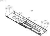
- FIG. 1 is a perspective view illustrating a sliding transport apparatus of a storage portion for a vehicle according to an embodiment of the present disclosure
- FIG. 2 is a perspective view illustrating a state in which a movable frame illustrated in FIG. 1 is slidably moved forward
- FIG. 3 is a front view illustrating the sliding transport apparatus of the storage portion for the vehicle illustrated in FIG. 1
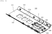
- FIG. 4 is a perspective view illustrating a configuration of a fixed frame according to an embodiment of the present disclosure
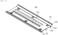
- FIG. 5 is a perspective view illustrating a configuration of the movable frame according to an embodiment of the present disclosure
- FIG. 6 is an exploded perspective view illustrating a configuration of a stopper according to an embodiment of the present disclosure
- FIG. 7 is a perspective view illustrating a bottom portion of the sliding transport apparatus illustrated in FIG. 2 .
- a sliding transport apparatus 100 of a storage portion for a vehicle may include: a fixed frame 110 provided such that the fixed frame 110 is stationary in a vehicle interior space; a movable frame 120 disposed on an upper portion of the fixed frame 110 and configured to be movable along a longitudinal direction of the fixed frame 110, the movable frame 120 having an upper portion on which the storage portion (not illustrated) is mounted; and a stopper 200 provided detachably on the fixed frame 110, the stopper 200 being inserted into a guide long hole 121a formed in the movable frame 120, thereby limiting a movement distance of the movable frame 120.
- the fixed frame 110 is a component which is mounted inside the vehicle and which has a predetermined length and a predetermined width, and may be manufactured by an extrusion method.
- the fixed frame 110 may include: a floor member 111 provided such that the floor member 111 is stationary in the vehicle interior space; and a first inclined member 112 that protrudes in a direction inclined upwardly from opposite sides in a width direction of the floor member 111, the first inclined member 112 on which a plurality of rail casters C configured to move the movable frame 120 is rotatably mounted.
- the floor member 111 may be mounted between a driver seat and a passenger seat, or may be mounted at a dashboard that is disposed in the front of the vehicle interior space.
- the first inclined member 112 is provided along an entire of the longitudinal direction of the floor member 111 from end portions in the width direction of the floor member 111.
- the first inclined member 112 provides a space where the plurality of rail casters C is capable of being rotatably mounted. In an embodiment of the present disclosure, it is illustrated in drawings that four rail casters C are provided on the first inclined member 112.
- the first inclined member 112 may be disposed such that the first inclined member 112 is inclined upwardly at an angle range of 10 degrees to 80 degrees from the end portions in the width direction of the floor member 111.
- the plurality of rail casters C provided on the first inclined member 112 may be rotatably mounted on the first inclined member 112 while having an inclination angle equal to an inclination angle of the first inclined member 112. That is, as illustrated in FIG. 4 , since a shaft connected to the rail caster C is mounted in an inclination direction on the first inclined member 112, a rolling contact surface of the rail caster C may be disposed in the inclination direction.
- the movable frame 120 is also a component which is mounted inside the vehicle and which has a predetermined length and a predetermined width, and may be manufactured by an extrusion method.
- the movable frame 120 may include: an upper plate member 121 on which the storage portion is mounted on an upper surface thereof and in which the guide long hole 121a is formed; and a second inclined member 122 that protrudes in a direction inclined upwardly from opposite sides in a width direction of the upper plate member 121 while having an inclination angle equal to the inclination angle of the first inclined member 112, the second inclined member 122 having a rail groove 122a in which the rail caster C is accommodated.
- the upper plate member 121 is a component that is coupled to the storage portion, and has an area capable of supporting the storage portion.
- the upper plate member 121 is configured to be rectilinearly reciprocated along the longitudinal direction of the floor member 111 while being disposed so as to face the floor member 111.
- the guide long hole 121a formed in the upper plate member 121 is formed along a longitudinal direction of the upper plate member 121.
- a pair of guide long holes 121a spaced apart from each other by a predetermined distance is formed in a center portion of the upper plate member 121.
- the plurality of rail casters C provided on the first inclined member 112 of the fixed frame 110 is in rolling contact with any one guide protrusion 122b or 122c among a pair of guide protrusions 122b and 122c formed on the second inclined member 122.
- any one rail caster C may be in rolling contact with the guide protrusion 122c provided at a lower end of the second inclined member 122, and another rail caster C disposed on a first side of the first inclined member 112 may be in rolling contact with the guide protrusion 122b provided at an upper end of the second inclined member 122.
- the plurality of rail casters C provided on the first inclined member 112 is alternately in rolling contact with any one of the guide protrusions 122b and 122c among the pair of guide protrusions 122b and 122c formed on the second inclined member 122.
- the four rail casters C provided on the first inclined member 112 may be disposed such that two rail casters C are in rolling contact with the guide protrusion 122b that is positioned at the upper end of the second inclined member 122 and the remaining two rail casters C are in rolling contact with the guide protrusion 122c that is positioned at the lower end of the second inclined member 122.
- the plurality of rail casters C is in selectively rolling contact with the guide protrusion 122b positioned at the upper end of the second inclined member 122 and with the guide protrusion 122c positioned at the lower end of the second inclined member 122, a rolling frictional force generated between the rail casters C and the second inclined member 122 may be reduced and, accordingly, the movable frame 120 may be rectilinearly reciprocated on the fixed frame 110 easily.
- the movable frame 120 may further include a guide member 123 that protrudes vertically downward from a center of a bottom portion of the upper plate member 121.
- the guide member 123 serves to reinforce rigidity of the upper plate member 121, and serves to prevent the upper plate member 121 from being moved in left and right directions when the upper plate member 121 is slidably moved. That is, as illustrated in FIG. 3 , since the guide member 123 is slidably moved while being in contact with a pair of guide rollers 240 of the stopper 200 that will be described later, left and right movements of the upper plate member 121 may be prevented.
- the stopper 200 is configured to limit a maximum withdrawal distance of the movable frame 120, and is also configured to prevent the left and right movements of the movable frame 120 by cooperating with the guide long holes 121a formed in the upper plate member 121 during a process in which the movable frame 120 is slidably moved in a rectilinear direction.
- the stopper 200 may include: a plate 210 mounted on a bottom surface of the floor member 111; an insertion member 220 which is integrally connected to the plate 210 and which protrudes upward from an upper surface of the plate 210, the insertion member 220 being inserted into the guide long hole 121a; and a buffer member 230 having a through-hole 231 into which the insertion member 220 is capable of being inserted, the buffer member 230 surrounding a circumferential portion of the insertion member 220.
- the plate 210 may be mounted on the bottom surface of the floor member 111. At this time, the plate 210 may be mounted on the bottom surface of the floor member 111 while blocking any one of a plurality of opening portions 111a among the plurality of opening portions 111a formed such that the plurality of opening portions 111a is spaced apart from each other by a predetermined distance along the longitudinal direction of the floor member 111.
- the pair of guide rollers 240 spaced apart from each other by a predetermined distance is rotatably mounted on the upper surface of the plate 210.
- the pair of guide rollers 240 may be manufactured from rubber material or urethane material, and may be in rolling contact with a first side surface or a second side surface of the guide member 123 when the guide member 123 is slidably moved.
- the pair of guide rollers 240 is not limited to serving as guides and also serves to control an operation force of the movable frame 120.
- the insertion member 220 may be inserted into the guide long hole 121a formed in the upper plate member 121. At this time, an upper end portion of the insertion member 220 is partially exposed to an upper portion of the upper plate member 121 via the guide long hole 121a.
- the buffer member 230 may be manufactured from rubber material having an elastic restoring force, and the through-hole 231 into which the insertion member 220 is capable of being inserted in a forcibly fitting manner is formed in a center of the buffer member 230.
- a separation prevention member 221 configured to prevent the buffer member 230 from being separated is provided on an upper end of the insertion member 220.
- the stopper 200 described above serves to limit a maximum movement distance of the movable frame 120, and also serves to relieve a shock that occurs during a process in which the movable frame 120 is slidably moved and then stopped.
- a second end side in a longitudinal direction of the guide long hole 121a may be in contact with a second side of the buffer member 230 of the stopper 200. Then, the sliding movement of the movable frame 120 may be limited.
- a moment when the buffer member 230 is in contact with the second end side in the longitudinal direction of the guide long hole 121a may be referred to as a state in which the movable frame 120 is maximally withdrawn on the fixed frame 110.
- a first end side in the longitudinal direction of the guide long hole 121a may be in contact with a first side of the buffer member 230 of the stopper 200 as illustrated in FIG. 1 . Then, a storage space of the storage portion and the movable frame 120 are not exposed to the outside.
- the stopper 200 may limit the maximum movement distance of the movable frame 120, and may relieve a shock that occurs in the process.
- the stopper 200 since the stopper 200 is in a state in which the stopper 200 is inserted into the guide long hole 121a, a phenomenon in which the movable frame is shaken in the left and right directions in the process of rectilinearly reciprocating the movable frame 120 may be prevented by the stopper 200. That is, even when a force in the left and right directions is generated on the movable frame 120, an inner side portion of the guide long hole 121a of the upper plate member 121 is in contact with the buffer member 230 of the stopper 200, so that the left and right movements of the movable frame 120 may be prevented.
- the maximum movement distance of the movable frame 120 may be set by changing a position of the stopper 200 mounted on the fixed frame 110. That is, among the plurality of opening portions 111a provided in the floor member 111, the stopper 200 may be optionally mounted on any one opening portion 111a, so that the maximum movement distance (the withdrawal distance of the storage portion) of the movable frame 120 may be set.
- the maximum movement distance of the movable frame 120 (the withdrawal distance of the storage portion) may be set in consideration of a volume of the storage portion, the vehicle interior space, and a mounting position of the fixed frame 110.
- the maximum movement distance of the movable frame 120 becomes the shortest.
- the maximum movement distance of the movable frame 120 may become the longest.
- the present disclosure may be applied and sold in the automotive industry.
Landscapes
- Engineering & Computer Science (AREA)
- Mechanical Engineering (AREA)
- Transportation (AREA)
- Aviation & Aerospace Engineering (AREA)
- Handcart (AREA)
- Vehicle Step Arrangements And Article Storage (AREA)
Abstract
Description
- The present disclosure relates to a sliding transport apparatus of a storage portion for a vehicle. More particularly, the present disclosure relates to a sliding transport apparatus of a storage portion for a vehicle, the sliding transport apparatus being applied in a glove box, a console box, or a withdrawal tray provided inside the vehicle and being configured such that the storage portion or the tray can be stably and slidably transported by a user.
- Generally, a console box, a glove box, an overhead box, and so on for storing items are provided in an interior of a vehicle.
- In a storage space formed by such boxes, items used in the interior of the vehicle are stored, and the boxes are mounted such that the boxes are capable of being opened and closed for the convenience of a user. For example, the glove box is mounted on a dashboard disposed in the front of a passenger seat of the vehicle such that the glove box is capable of being opened and closed, and the console box is mounted between a driver seat and the passenger seat such that the console box is capable of being opened and closed.
- As a recent trend for a vehicle to be equipped with an autonomous driving system, utilization of an interior space of a vehicle is becoming important. In addition, since a battery pack using electric energy or hydrogen energy is used as a driving power source instead of an existing internal combustion engine, an interior space of a vehicle is expanded as the number of internal components of the vehicle decreases.
- Therefore, a method of expanding a space in which items can be stored by changing a glove box or a console box in a hinged type to a glove box or a console box in a sliding type is researched, and a method of changing a position of a seat so that a driver or a passenger can perform various activities other than driving in an interior of a vehicle is being researched.
- Particularly, a conventional console box provided in the vehicle is disposed between a driver seat and a passenger seat while being in a state in which the console box is fixed and mounted at a vehicle body, and has an important role in forming a space at a front seat side. Therefore, as a range of autonomous driving expands, it is required to increase space utilization by configuring a console box to be movable. Particularly, research and development of an operation mechanism for a user to easily and quickly move a console box in a vehicle interior space is required.
- However, in slidably moving a glove box or a console box in a rectilinear direction during driving of a vehicle, a situation in which a storage portion is moved in a height direction (up and down directions) or a width direction (left and right directions) occurs, and there is a problem that noise is caused accordingly.
- Accordingly, the present applicant has proposed the present disclosure in order to solve the problem as described above, and
Korean Patent Application Publication No. 10-2005-0045430 - Accordingly, the present disclosure has been made keeping in mind the above problems occurring in the related art, and an objective of the present disclosure is to provide a sliding transport apparatus of a storage portion for a vehicle, the sliding transport apparatus being configured to prevent up and down direction movements or left and right direction movements of the storage portion and to stably and easily transport the storage portion when a user slidably opens or closes the storage portion that is provided in a vehicle interior space.
- In order to achieve the above objective, according to the present disclosure, there is provided a sliding transport apparatus of a storage portion for a vehicle, the sliding transport apparatus including: a fixed frame provided such that the fixed frame is stationary in a vehicle interior space; a movable frame disposed on an upper portion of the fixed frame and configured to be movable along a longitudinal direction of the fixed frame, the movable frame having an upper portion on which the storage portion is mounted; and a stopper provided detachably on the fixed frame, the stopper being inserted into a guide long hole formed in the movable frame, thereby limiting a movement distance of the movable frame.
- In addition, the fixed frame may include: a floor member provided such that the floor member is stationary in the vehicle interior space; and a first inclined member that protrudes in a direction inclined upwardly from opposite sides in a width direction of the floor member, the first inclined member on which a plurality of rail casters configured to move the movable frame is rotatably mounted.
- In addition, the movable frame may include: an upper plate member on which the storage portion is mounted and in which the guide long hole is formed; and a second inclined member that protrudes in a direction inclined upwardly from opposite sides in a width direction of the upper plate member while having an inclination angle equal to an inclination angle of the first inclined member, the second inclined member having a rail groove in which the plurality of rail casters is accommodated.
- In addition, the plurality of rail casters may be rotatably mounted on the first inclined member while having an inclination angle equal to an inclination angle of the first inclined member.
- In addition, the stopper may include: a plate mounted on a bottom surface of the floor member; an insertion member that protrudes upward from an upper surface of the plate, the insertion member being inserted into the guide long hole; and a buffer member having a through-hole into which the insertion member is capable of being inserted, the buffer member surrounding a circumferential portion of the insertion member.
- In addition, the movable frame may include a guide member that protrudes vertically downward from a center of a bottom portion of the upper plate member, and a guide roller in rolling contact with the guide member may be rotatably provided on the plate of the stopper with the guide member interposed therebetween.
- In addition, a plurality of opening portions disposed so as to be spaced apart from each other by a predetermined distance may be formed in the floor member along a longitudinal direction of the floor member, and the plate of the stopper may be provided on the floor member while blocking any one of the plurality of opening portions among the plurality of opening portions.
- In the sliding transport apparatus of the storage portion for the vehicle according to the present disclosure, since a configuration in which the storage portion provided in the interior space of the vehicle is slidably moved and opened is provided, a space in which items can be stored may be increased, and space utilization may be increased as the interior space of the vehicle is expanded.
- In addition, in the sliding transport apparatus of the storage portion for the vehicle according to the present disclosure, the sliding movement distance of the movable frame may be optionally set in consideration of a size of the interior space of the vehicle, a volume of the storage portion, and so on.
- In addition, in the sliding transport apparatus of the storage portion for the vehicle according to the present disclosure, a shock that occurs on the movable frame during a process in which the storage portion is slidably moved and stopped may be relieved.
- In addition, in the sliding transport apparatus of the storage portion for the vehicle according to the present disclosure, since a configuration preventing a situation in which the movable frame is moved in the up and down directions or the left and right directions is provided, a situation in which the storage portion is unintentionally shaken during the driving process of the vehicle or during a user's operation may be prevented.
-
-
FIG. 1 is a perspective view illustrating a sliding transport apparatus of a storage portion for a vehicle according to an embodiment of the present disclosure. -
FIG. 2 is a perspective view illustrating a state in which a movable frame illustrated inFIG. 1 is slidably moved forward. -
FIG. 3 is a front view illustrating the sliding transport apparatus of the storage portion for the vehicle illustrated inFIG. 1 . -
FIG. 4 is a perspective view illustrating a configuration of a fixed frame according to an embodiment of the present disclosure. -
FIG. 5 is a perspective view illustrating a configuration of the movable frame according to an embodiment of the present disclosure. -
FIG. 6 is an exploded perspective view illustrating a configuration of a stopper according to an embodiment of the present disclosure. -
FIG. 7 is a perspective view illustrating a bottom portion of the sliding transport apparatus illustrated inFIG. 2 . - Advantages and features of the present disclosure, and methods of achieving the same will become apparent with reference to the embodiments described below in detail in conjunction with the accompanying drawings.
- However, the present disclosure is not limited to the embodiments disclosed below, but may be implemented in various different forms. The present embodiments are intended to complete the disclosure of the present disclosure and provided to fully inform the skilled in the art to which the disclosure pertains of the scope of the disclosure. The disclosure is defined only by the scope of the claims.
- Hereinafter, a sliding transport apparatus of a storage portion for a vehicle according to an embodiment of the present disclosure will be described in detail with reference to
FIGS. 1 to 7 . In a description of the present disclosure, a detailed description of related known functions or configurations will be omitted to avoid making the essence of the present disclosure unclear. -
FIG. 1 is a perspective view illustrating a sliding transport apparatus of a storage portion for a vehicle according to an embodiment of the present disclosure,FIG. 2 is a perspective view illustrating a state in which a movable frame illustrated inFIG. 1 is slidably moved forward,FIG. 3 is a front view illustrating the sliding transport apparatus of the storage portion for the vehicle illustrated inFIG. 1 ,FIG. 4 is a perspective view illustrating a configuration of a fixed frame according to an embodiment of the present disclosure,FIG. 5 is a perspective view illustrating a configuration of the movable frame according to an embodiment of the present disclosure,FIG. 6 is an exploded perspective view illustrating a configuration of a stopper according to an embodiment of the present disclosure, andFIG. 7 is a perspective view illustrating a bottom portion of the sliding transport apparatus illustrated inFIG. 2 . - As illustrated in
FIG. 1 andFIG. 2 , asliding transport apparatus 100 of a storage portion for a vehicle according to an embodiment of the present disclosure may include: afixed frame 110 provided such that thefixed frame 110 is stationary in a vehicle interior space; amovable frame 120 disposed on an upper portion of thefixed frame 110 and configured to be movable along a longitudinal direction of thefixed frame 110, themovable frame 120 having an upper portion on which the storage portion (not illustrated) is mounted; and astopper 200 provided detachably on thefixed frame 110, thestopper 200 being inserted into a guidelong hole 121a formed in themovable frame 120, thereby limiting a movement distance of themovable frame 120. - The
fixed frame 110 is a component which is mounted inside the vehicle and which has a predetermined length and a predetermined width, and may be manufactured by an extrusion method. - As illustrated in
FIG. 3 andFIG. 4 , thefixed frame 110 may include: afloor member 111 provided such that thefloor member 111 is stationary in the vehicle interior space; and a firstinclined member 112 that protrudes in a direction inclined upwardly from opposite sides in a width direction of thefloor member 111, the firstinclined member 112 on which a plurality of rail casters C configured to move themovable frame 120 is rotatably mounted. - The
floor member 111 may be mounted between a driver seat and a passenger seat, or may be mounted at a dashboard that is disposed in the front of the vehicle interior space. - The first
inclined member 112 is provided along an entire of the longitudinal direction of thefloor member 111 from end portions in the width direction of thefloor member 111. The firstinclined member 112 provides a space where the plurality of rail casters C is capable of being rotatably mounted. In an embodiment of the present disclosure, it is illustrated in drawings that four rail casters C are provided on the firstinclined member 112. - The first
inclined member 112 may be disposed such that the firstinclined member 112 is inclined upwardly at an angle range of 10 degrees to 80 degrees from the end portions in the width direction of thefloor member 111. - In addition, the plurality of rail casters C provided on the first
inclined member 112 may be rotatably mounted on the firstinclined member 112 while having an inclination angle equal to an inclination angle of the firstinclined member 112. That is, as illustrated inFIG. 4 , since a shaft connected to the rail caster C is mounted in an inclination direction on the firstinclined member 112, a rolling contact surface of the rail caster C may be disposed in the inclination direction. - The
movable frame 120 is also a component which is mounted inside the vehicle and which has a predetermined length and a predetermined width, and may be manufactured by an extrusion method. - As illustrated in
FIG. 3 andFIG. 5 , themovable frame 120 may include: anupper plate member 121 on which the storage portion is mounted on an upper surface thereof and in which the guidelong hole 121a is formed; and a secondinclined member 122 that protrudes in a direction inclined upwardly from opposite sides in a width direction of theupper plate member 121 while having an inclination angle equal to the inclination angle of the firstinclined member 112, the secondinclined member 122 having arail groove 122a in which the rail caster C is accommodated. - The
upper plate member 121 is a component that is coupled to the storage portion, and has an area capable of supporting the storage portion. - The
upper plate member 121 is configured to be rectilinearly reciprocated along the longitudinal direction of thefloor member 111 while being disposed so as to face thefloor member 111. - The guide
long hole 121a formed in theupper plate member 121 is formed along a longitudinal direction of theupper plate member 121. In an embodiment of the present disclosure, a pair of guidelong holes 121a spaced apart from each other by a predetermined distance is formed in a center portion of theupper plate member 121. - Meanwhile, the plurality of rail casters C provided on the first
inclined member 112 of the fixedframe 110 is in rolling contact with any oneguide protrusion guide protrusions inclined member 122. - As illustrated in
FIG. 4 , among the plurality of rail casters C provided on the firstinclined member 112, any one rail caster C may be in rolling contact with theguide protrusion 122c provided at a lower end of the secondinclined member 122, and another rail caster C disposed on a first side of the firstinclined member 112 may be in rolling contact with theguide protrusion 122b provided at an upper end of the secondinclined member 122. - That is, the plurality of rail casters C provided on the first
inclined member 112 is alternately in rolling contact with any one of theguide protrusions guide protrusions inclined member 122. - In an embodiment of the present disclosure, the four rail casters C provided on the first
inclined member 112 may be disposed such that two rail casters C are in rolling contact with theguide protrusion 122b that is positioned at the upper end of the secondinclined member 122 and the remaining two rail casters C are in rolling contact with theguide protrusion 122c that is positioned at the lower end of the secondinclined member 122. - As such, since the plurality of rail casters C is in selectively rolling contact with the
guide protrusion 122b positioned at the upper end of the secondinclined member 122 and with theguide protrusion 122c positioned at the lower end of the secondinclined member 122, a rolling frictional force generated between the rail casters C and the secondinclined member 122 may be reduced and, accordingly, themovable frame 120 may be rectilinearly reciprocated on the fixedframe 110 easily. - Meanwhile, the
movable frame 120 may further include aguide member 123 that protrudes vertically downward from a center of a bottom portion of theupper plate member 121. - The
guide member 123 serves to reinforce rigidity of theupper plate member 121, and serves to prevent theupper plate member 121 from being moved in left and right directions when theupper plate member 121 is slidably moved. That is, as illustrated inFIG. 3 , since theguide member 123 is slidably moved while being in contact with a pair ofguide rollers 240 of thestopper 200 that will be described later, left and right movements of theupper plate member 121 may be prevented. - The
stopper 200 is configured to limit a maximum withdrawal distance of themovable frame 120, and is also configured to prevent the left and right movements of themovable frame 120 by cooperating with the guidelong holes 121a formed in theupper plate member 121 during a process in which themovable frame 120 is slidably moved in a rectilinear direction. - As illustrated in
FIG. 4 andFIG. 6 , thestopper 200 may include: aplate 210 mounted on a bottom surface of thefloor member 111; aninsertion member 220 which is integrally connected to theplate 210 and which protrudes upward from an upper surface of theplate 210, theinsertion member 220 being inserted into the guidelong hole 121a; and abuffer member 230 having a through-hole 231 into which theinsertion member 220 is capable of being inserted, thebuffer member 230 surrounding a circumferential portion of theinsertion member 220. - As illustrated in
FIG. 7 , theplate 210 may be mounted on the bottom surface of thefloor member 111. At this time, theplate 210 may be mounted on the bottom surface of thefloor member 111 while blocking any one of a plurality of openingportions 111a among the plurality of openingportions 111a formed such that the plurality of openingportions 111a is spaced apart from each other by a predetermined distance along the longitudinal direction of thefloor member 111. - In addition, the pair of
guide rollers 240 spaced apart from each other by a predetermined distance is rotatably mounted on the upper surface of theplate 210. The pair ofguide rollers 240 may be manufactured from rubber material or urethane material, and may be in rolling contact with a first side surface or a second side surface of theguide member 123 when theguide member 123 is slidably moved. The pair ofguide rollers 240 is not limited to serving as guides and also serves to control an operation force of themovable frame 120. - The
insertion member 220 may be inserted into the guidelong hole 121a formed in theupper plate member 121. At this time, an upper end portion of theinsertion member 220 is partially exposed to an upper portion of theupper plate member 121 via the guidelong hole 121a. - The
buffer member 230 may be manufactured from rubber material having an elastic restoring force, and the through-hole 231 into which theinsertion member 220 is capable of being inserted in a forcibly fitting manner is formed in a center of thebuffer member 230. - In addition, a
separation prevention member 221 configured to prevent thebuffer member 230 from being separated is provided on an upper end of theinsertion member 220. - As described above, the
stopper 200 described above serves to limit a maximum movement distance of themovable frame 120, and also serves to relieve a shock that occurs during a process in which themovable frame 120 is slidably moved and then stopped. - As illustrated in
FIG. 2 , when themovable frame 120 is slidably moved in a first direction on the fixedframe 110 so as to withdraw the storage portion, a second end side in a longitudinal direction of the guidelong hole 121a may be in contact with a second side of thebuffer member 230 of thestopper 200. Then, the sliding movement of themovable frame 120 may be limited. In addition, a moment when thebuffer member 230 is in contact with the second end side in the longitudinal direction of the guidelong hole 121a may be referred to as a state in which themovable frame 120 is maximally withdrawn on the fixedframe 110. - Conversely, when the
movable frame 120 that is withdrawn is slidably moved in a second direction in order to return the storage portion to an original state, a first end side in the longitudinal direction of the guidelong hole 121a may be in contact with a first side of thebuffer member 230 of thestopper 200 as illustrated inFIG. 1 . Then, a storage space of the storage portion and themovable frame 120 are not exposed to the outside. - As described above, the
stopper 200 may limit the maximum movement distance of themovable frame 120, and may relieve a shock that occurs in the process. In addition, since thestopper 200 is in a state in which thestopper 200 is inserted into the guidelong hole 121a, a phenomenon in which the movable frame is shaken in the left and right directions in the process of rectilinearly reciprocating themovable frame 120 may be prevented by thestopper 200. That is, even when a force in the left and right directions is generated on themovable frame 120, an inner side portion of the guidelong hole 121a of theupper plate member 121 is in contact with thebuffer member 230 of thestopper 200, so that the left and right movements of themovable frame 120 may be prevented. - Meanwhile, the maximum movement distance of the
movable frame 120 may be set by changing a position of thestopper 200 mounted on the fixedframe 110. That is, among the plurality of openingportions 111a provided in thefloor member 111, thestopper 200 may be optionally mounted on any oneopening portion 111a, so that the maximum movement distance (the withdrawal distance of the storage portion) of themovable frame 120 may be set. For reference, the maximum movement distance of the movable frame 120 (the withdrawal distance of the storage portion) may be set in consideration of a volume of the storage portion, the vehicle interior space, and a mounting position of the fixedframe 110. - For example, when the
stopper 200 is mounted on theopening portion 111a formed in a second end side in the longitudinal direction of thefloor member 111, the maximum movement distance of themovable frame 120 becomes the shortest. Conversely, as illustrated inFIG. 2 andFIG. 7 , when thestopper 200 is mounted on theopening portion 111a formed in a first end side in the longitudinal direction of thefloor member 111, the maximum movement distance of themovable frame 120 may become the longest. - Although detailed exemplary embodiments according to the present disclosure have been described so far, obviously, various modifications may be made without departing from the scope of the present disclosure.
- Therefore, the scope of the present disclosure should not be limited to the described exemplary embodiments, and should be determined not only by the scope of the claims to be described later, but also by the scope and equivalents of the claims.
- The present disclosure may be applied and sold in the automotive industry.
Claims (7)
- A sliding transport apparatus of a storage portion for a vehicle, the sliding transport apparatus comprising:a fixed frame provided such that the fixed frame is stationary in a vehicle interior space;a movable frame disposed on an upper portion of the fixed frame and configured to be movable along a longitudinal direction of the fixed frame, the movable frame having an upper portion on which the storage portion is mounted; anda stopper provided detachably on the fixed frame, the stopper being inserted into a guide long hole formed in the movable frame, thereby limiting a movement distance of the movable frame.
- The sliding transport apparatus of claim 1, wherein the fixed frame comprises:a floor member provided such that the floor member is stationary in the vehicle interior space; anda first inclined member that protrudes in a direction inclined upwardly from opposite sides in a width direction of the floor member, the first inclined member on which a plurality of rail casters configured to move the movable frame is rotatably mounted.
- The sliding transport apparatus of claim 2, wherein the movable frame comprises:an upper plate member on which the storage portion is mounted and in which the guide long hole is formed; anda second inclined member that protrudes in a direction inclined upwardly from opposite sides in a width direction of the upper plate member while having an inclination angle equal to an inclination angle of the first inclined member, the second inclined member having a rail groove in which the plurality of rail casters is accommodated.
- The sliding transport apparatus of claim 2, wherein the plurality of rail casters is rotatably mounted on the first inclined member while having an inclination angle equal to an inclination angle of the first inclined member.
- The sliding transport apparatus of claim 2, wherein the stopper comprises:a plate mounted on a bottom surface of the floor member;an insertion member that protrudes upward from an upper surface of the plate, the insertion member being inserted into the guide long hole; anda buffer member having a through-hole into which the insertion member is capable of being inserted, the buffer member surrounding a circumferential portion of the insertion member.
- The sliding transport apparatus of claim 5, wherein the movable frame comprises a guide member that protrudes vertically downward from a center of a bottom portion of the upper plate member, and a guide roller in rolling contact with the guide member is rotatably provided on the plate of the stopper with the guide member interposed therebetween.
- The sliding transport apparatus of claim 6, wherein a plurality of opening portions disposed so as to be spaced apart from each other by a predetermined distance is formed in the floor member along a longitudinal direction of the floor member, and the plate of the stopper is provided on the floor member while blocking any one of the plurality of opening portions among the plurality of opening portions.
Applications Claiming Priority (2)
| Application Number | Priority Date | Filing Date | Title |
|---|---|---|---|
| KR1020220055385A KR102689989B1 (en) | 2022-05-04 | 2022-05-04 | Sliding transfer device of the vehicle |
| PCT/KR2022/012472 WO2023214622A1 (en) | 2022-05-04 | 2022-08-22 | Sliding transfer device for storage unit for vehicle |
Publications (2)
| Publication Number | Publication Date |
|---|---|
| EP4520595A1 true EP4520595A1 (en) | 2025-03-12 |
| EP4520595A4 EP4520595A4 (en) | 2026-04-22 |
Family
ID=88646555
Family Applications (1)
| Application Number | Title | Priority Date | Filing Date |
|---|---|---|---|
| EP22896835.0A Pending EP4520595A4 (en) | 2022-05-04 | 2022-08-22 | Sliding transmission device for a bearing unit for a vehicle |
Country Status (5)
| Country | Link |
|---|---|
| US (1) | US12459439B2 (en) |
| EP (1) | EP4520595A4 (en) |
| KR (4) | KR102689989B1 (en) |
| CN (1) | CN119032026A (en) |
| WO (1) | WO2023214622A1 (en) |
Families Citing this family (4)
| Publication number | Priority date | Publication date | Assignee | Title |
|---|---|---|---|---|
| EP4420932A4 (en) * | 2021-10-18 | 2025-10-08 | Kbi Dongkook Ind Co Ltd | SLIDING CONVEYOR DEVICE FOR A STORAGE PART FOR A VEHICLE |
| KR102689989B1 (en) * | 2022-05-04 | 2024-07-30 | 케이비아이동국실업 주식회사 | Sliding transfer device of the vehicle |
| KR20240108586A (en) * | 2023-01-02 | 2024-07-09 | 현대자동차주식회사 | Luggage loading device of vehicle |
| KR20240176515A (en) * | 2023-06-16 | 2024-12-24 | 현대자동차주식회사 | Center console device for vehicle |
Family Cites Families (39)
| Publication number | Priority date | Publication date | Assignee | Title |
|---|---|---|---|---|
| US5046861A (en) * | 1989-12-05 | 1991-09-10 | Siemens Transmission Systems, Inc. | Vertically oriented drawer slide |
| JPH10239638A (en) | 1996-12-26 | 1998-09-11 | Nec Corp | Optical circulator |
| KR200143812Y1 (en) * | 1997-04-30 | 1999-06-15 | 양재신 | Shock absorbers in guide bars in the glove box of a car |
| JP3831827B2 (en) | 1997-05-30 | 2006-10-11 | 株式会社イノアックコーポレーション | Slider for movable console box |
| CA2245311C (en) * | 1997-08-19 | 2006-10-24 | Atoma International Inc. | Multi-position sliding center console with adjustable table top |
| JP2000264132A (en) * | 1999-03-12 | 2000-09-26 | Oi Seisakusho Co Ltd | Console slide support device |
| AT410165B (en) * | 1999-10-18 | 2003-02-25 | Fulterer Gmbh | EXTENSION DEVICE AND CARAVAN OR MOTORHOME WITH EXTENDABLE SIDE PANELS |
| US6382480B1 (en) * | 1999-10-29 | 2002-05-07 | Jac Products, Inc. | Bicycle carrier apparatus adapted for use within a cargo area of a vehicle |
| US6981728B2 (en) * | 1999-11-23 | 2006-01-03 | Happijac Company | Sliding mechanisms and systems |
| FR2822770B1 (en) * | 2001-03-30 | 2003-08-15 | Sai Automotive Allibert Ind | DEVICE INCLUDING A REMOVABLE SLIDING CENTER CONSOLE |
| DE20214711U1 (en) * | 2002-09-23 | 2004-02-19 | Seeber Ag & Co. Kg | Lid supported on a support |
| KR100558409B1 (en) | 2003-11-11 | 2006-03-10 | 기아자동차주식회사 | Car Console Box |
| KR200357471Y1 (en) * | 2004-02-23 | 2004-07-30 | 주식회사다스 | Lock guide of seat locking device for vehicle |
| JP2006290227A (en) * | 2005-04-13 | 2006-10-26 | Nissan Motor Co Ltd | Car console power supply structure |
| KR200395000Y1 (en) | 2005-04-14 | 2005-09-07 | (주)디디디 | Rail Structure separable of seat for automobile |
| GB0616733D0 (en) * | 2006-08-23 | 2006-10-04 | Accuride Int Ltd | A sliding support assembly |
| US7591498B2 (en) * | 2007-05-24 | 2009-09-22 | Irvin Automotive Products, Inc. | Sliding console |
| JP2009006737A (en) * | 2007-06-26 | 2009-01-15 | Molten Corp | Sliding mechanism |
| NL2001766C2 (en) * | 2008-07-04 | 2010-01-05 | Thomas Regout Internat B V | Sliding guide and an armrest provided with such a sliding guide. |
| KR20100105923A (en) | 2009-03-23 | 2010-10-01 | 권해경 | A slider |
| US8235442B2 (en) * | 2009-12-11 | 2012-08-07 | Nissan North America, Inc. | Console lid slide rail attachment |
| KR101163450B1 (en) * | 2010-07-29 | 2012-07-18 | 현대자동차주식회사 | Sliding armrest for vehicle |
| DE102010036000B4 (en) * | 2010-08-31 | 2014-11-27 | F.S. Fehrer Automotive Gmbh | Center console with linear guide |
| JP5632727B2 (en) | 2010-12-13 | 2014-11-26 | シロキ工業株式会社 | Slide rail device for vehicle |
| CN102612285B (en) * | 2011-01-21 | 2015-04-15 | 中山市云创知识产权服务有限公司 | Opening and closing mechanism |
| KR101260842B1 (en) * | 2011-03-17 | 2013-05-06 | 덕양산업 주식회사 | Arm rest module with vibration damper system |
| WO2014036260A1 (en) * | 2012-08-31 | 2014-03-06 | Johnson Controls Technology Company | Frictional sliding mechanism for interior assembly of a vehicle |
| US9199562B2 (en) * | 2014-03-14 | 2015-12-01 | Honda Motor Co., Ltd. | Vehicle console with sliding and pivoting armrest assembly |
| KR20160121816A (en) * | 2015-04-13 | 2016-10-21 | 현대자동차주식회사 | Sliding armrest device for vehicle |
| KR101709162B1 (en) * | 2015-06-19 | 2017-02-22 | (주)협진피엘 | Armrest sliding rail for car |
| KR20180040383A (en) * | 2016-10-12 | 2018-04-20 | 주식회사 서연이화 | Sliding structure of console armrest |
| JP2018090053A (en) * | 2016-12-01 | 2018-06-14 | Ntn株式会社 | Slide rail support structure |
| KR101987006B1 (en) * | 2017-11-10 | 2019-06-10 | 주식회사 서연이화 | Electric-powered sliding console for vehicle |
| CN109050414A (en) * | 2018-07-10 | 2018-12-21 | 上海延锋金桥汽车饰件系统有限公司 | A kind of vehicle mounted electric sliding rail |
| CN210033237U (en) | 2019-03-20 | 2020-02-07 | 广州市科灵电子工程有限公司 | A retractable door guide windproof device |
| KR102390626B1 (en) * | 2020-07-29 | 2022-04-25 | 케이비아이동국실업 주식회사 | Glove box shake prevention structure |
| KR102598407B1 (en) * | 2021-09-16 | 2023-11-03 | 현대자동차 주식회사 | Sliding type console box |
| EP4420932A4 (en) * | 2021-10-18 | 2025-10-08 | Kbi Dongkook Ind Co Ltd | SLIDING CONVEYOR DEVICE FOR A STORAGE PART FOR A VEHICLE |
| KR102689989B1 (en) * | 2022-05-04 | 2024-07-30 | 케이비아이동국실업 주식회사 | Sliding transfer device of the vehicle |
-
2022
- 2022-05-04 KR KR1020220055385A patent/KR102689989B1/en active Active
- 2022-08-22 EP EP22896835.0A patent/EP4520595A4/en active Pending
- 2022-08-22 CN CN202280095566.XA patent/CN119032026A/en active Pending
- 2022-08-22 WO PCT/KR2022/012472 patent/WO2023214622A1/en not_active Ceased
-
2023
- 2023-05-30 US US18/325,398 patent/US12459439B2/en active Active
-
2024
- 2024-07-25 KR KR1020240098703A patent/KR102792788B1/en active Active
- 2024-07-25 KR KR1020240098704A patent/KR102792789B1/en active Active
- 2024-07-25 KR KR1020240098702A patent/KR102733441B1/en active Active
Also Published As
| Publication number | Publication date |
|---|---|
| KR20240116888A (en) | 2024-07-30 |
| KR102792788B1 (en) | 2025-04-08 |
| KR20240119042A (en) | 2024-08-06 |
| US20230356663A1 (en) | 2023-11-09 |
| KR20240119041A (en) | 2024-08-06 |
| EP4520595A4 (en) | 2026-04-22 |
| KR102733441B1 (en) | 2024-11-25 |
| KR102689989B1 (en) | 2024-07-30 |
| KR102733441B9 (en) | 2025-03-10 |
| US12459439B2 (en) | 2025-11-04 |
| KR102792789B1 (en) | 2025-04-08 |
| KR20230155775A (en) | 2023-11-13 |
| WO2023214622A1 (en) | 2023-11-09 |
| CN119032026A (en) | 2024-11-26 |
Similar Documents
| Publication | Publication Date | Title |
|---|---|---|
| US12459439B2 (en) | Sliding transport apparatus of storage portion for vehicle | |
| US12472876B2 (en) | Sliding transport apparatus of storage portion for vehicle | |
| KR102689990B1 (en) | Sliding transfer device of the vehicle | |
| US6702241B2 (en) | Cup holder | |
| US11766970B2 (en) | Storage box | |
| US11148599B2 (en) | Cup holders within console assemblies for vehicles | |
| EP3275735B1 (en) | A motor vehicle drawer assembly | |
| CN114056240A (en) | Movement preventing structure for article box | |
| KR100559704B1 (en) | Cup holder device | |
| JP6841923B2 (en) | Container storage structure | |
| US12370934B2 (en) | Table device | |
| KR102687871B1 (en) | Sliding transfer device of the vehicle | |
| KR20190057899A (en) | Seat rail for car | |
| EP4001015B1 (en) | Sliding type glove box | |
| EP4309956A1 (en) | Sliding-type glove box | |
| KR102786174B1 (en) | Sliding transport device with shielding rubber applied | |
| JP7800819B2 (en) | Smartphone holding structure for vehicles | |
| JP7841358B2 (en) | Vehicle-mounted storage device | |
| JP2023156023A (en) | On-vehicle drawer structure | |
| JPH10181393A (en) | Seat for automobile | |
| JP2023012585A (en) | Container holding structure |
Legal Events
| Date | Code | Title | Description |
|---|---|---|---|
| STAA | Information on the status of an ep patent application or granted ep patent |
Free format text: STATUS: UNKNOWN |
|
| STAA | Information on the status of an ep patent application or granted ep patent |
Free format text: STATUS: THE INTERNATIONAL PUBLICATION HAS BEEN MADE |
|
| PUAI | Public reference made under article 153(3) epc to a published international application that has entered the european phase |
Free format text: ORIGINAL CODE: 0009012 |
|
| STAA | Information on the status of an ep patent application or granted ep patent |
Free format text: STATUS: REQUEST FOR EXAMINATION WAS MADE |
|
| 17P | Request for examination filed |
Effective date: 20230531 |
|
| AK | Designated contracting states |
Kind code of ref document: A1 Designated state(s): AL AT BE BG CH CY CZ DE DK EE ES FI FR GB GR HR HU IE IS IT LI LT LU LV MC MK MT NL NO PL PT RO RS SE SI SK SM TR |
|
| DAV | Request for validation of the european patent (deleted) | ||
| DAX | Request for extension of the european patent (deleted) | ||
| A4 | Supplementary search report drawn up and despatched |
Effective date: 20260319 |
|
| RIC1 | Information provided on ipc code assigned before grant |
Ipc: B60R 7/04 20060101AFI20260313BHEP Ipc: B60N 2/75 20180101ALI20260313BHEP Ipc: B60R 11/00 20060101ALI20260313BHEP |