EP4520562A1 - Door for a motor vehicle - Google Patents
Door for a motor vehicle Download PDFInfo
- Publication number
- EP4520562A1 EP4520562A1 EP24198627.2A EP24198627A EP4520562A1 EP 4520562 A1 EP4520562 A1 EP 4520562A1 EP 24198627 A EP24198627 A EP 24198627A EP 4520562 A1 EP4520562 A1 EP 4520562A1
- Authority
- EP
- European Patent Office
- Prior art keywords
- door
- wall
- support body
- ratchet
- lock
- Prior art date
- Legal status (The legal status is an assumption and is not a legal conclusion. Google has not performed a legal analysis and makes no representation as to the accuracy of the status listed.)
- Granted
Links
Images



Classifications
-
- E—FIXED CONSTRUCTIONS
- E05—LOCKS; KEYS; WINDOW OR DOOR FITTINGS; SAFES
- E05B—LOCKS; ACCESSORIES THEREFOR; HANDCUFFS
- E05B77/00—Vehicle locks characterised by special functions or purposes
- E05B77/02—Vehicle locks characterised by special functions or purposes for accident situations
- E05B77/04—Preventing unwanted lock actuation, e.g. unlatching, at the moment of collision
-
- B—PERFORMING OPERATIONS; TRANSPORTING
- B60—VEHICLES IN GENERAL
- B60J—WINDOWS, WINDSCREENS, NON-FIXED ROOFS, DOORS, OR SIMILAR DEVICES FOR VEHICLES; REMOVABLE EXTERNAL PROTECTIVE COVERINGS SPECIALLY ADAPTED FOR VEHICLES
- B60J5/00—Doors
- B60J5/04—Doors arranged at the vehicle sides
- B60J5/042—Reinforcement elements
- B60J5/0456—Behaviour during impact
- B60J5/0461—Behaviour during impact characterised by a pre-defined mode of deformation or displacement in order to absorb impact
-
- E—FIXED CONSTRUCTIONS
- E05—LOCKS; KEYS; WINDOW OR DOOR FITTINGS; SAFES
- E05B—LOCKS; ACCESSORIES THEREFOR; HANDCUFFS
- E05B17/00—Accessories in connection with locks
- E05B17/0054—Fraction or shear lines; Slip-clutches, resilient parts or the like for preventing damage when forced or slammed
- E05B17/0062—Fraction or shear lines; Slip-clutches, resilient parts or the like for preventing damage when forced or slammed with destructive disengagement
-
- E—FIXED CONSTRUCTIONS
- E05—LOCKS; KEYS; WINDOW OR DOOR FITTINGS; SAFES
- E05B—LOCKS; ACCESSORIES THEREFOR; HANDCUFFS
- E05B79/00—Mounting or connecting vehicle locks or parts thereof
- E05B79/10—Connections between movable lock parts
- E05B79/20—Connections between movable lock parts using flexible connections, e.g. Bowden cables
-
- E—FIXED CONSTRUCTIONS
- E05—LOCKS; KEYS; WINDOW OR DOOR FITTINGS; SAFES
- E05B—LOCKS; ACCESSORIES THEREFOR; HANDCUFFS
- E05B79/00—Mounting or connecting vehicle locks or parts thereof
- E05B79/10—Connections between movable lock parts
- E05B79/22—Operative connections between handles, sill buttons or lock knobs and the lock unit
Definitions
- the invention relates to a door assembly for a motor vehicle.
- Motor vehicles which basically comprise a body defining a passenger compartment and a pair of front doors hinged relative to the body.
- Each front door is, in a known manner, movable between:
- Each door basically comprises:
- the pillar is located on the side opposite an edge of the door hinged to the body of the motor vehicle.
- the front door on the driver's side further comprises:
- the lock comprises, in a known manner:
- the activation of the handle determines the activation of a microswitch, which generates a control signal for the opening mechanism, which causes the latter to shift from the closed configuration to the open configuration.
- the lock further comprises an electric back-up system and a mechanical back-up system able to allow the opening mechanism to be operated in case the microswitch is not electrically powered, for example due to the fact that the motor vehicle battery is momentarily low.
- the electric back-up system basically comprises a capacitive diode, which ensures a limited number of transitions of the opening mechanism from the closed configuration to the open configuration, even in the absence of an electrical power supply.
- the mechanical back-up system comprises, in turn, a Bowden cable, which can be operated by the ratchet and is connected to the opening mechanism so as to cause it to shift from the closed configuration to the open configuration.
- the Bowden cable is at least partly housed in a seat adjacent to the ratchet and defined by the support body.
- the seat of the Bowden cable is adjacent to further components housed inside the compartment, for example parts of the lock, of the window regulators or sheet metal reinforcements.
- the Applicant found out that, in case of a side impact of the motor vehicle, the intrusion of the support body towards the inside of the vehicle could lead to a pulling of the Bowden cable, due to an excess relative displacement of the ratchet relative to the support body or because of the presence of an obstacle that prevents the Bowden cable from following the ratchet without being pulled.
- the object of the invention is to provide a door for a motor vehicle, which allows manufacturers to fulfil the aforesaid need in a simple and economic fashion.
- number 1 indicates a motor vehicle.
- the motor vehicle 1 comprises a body 2 delimiting a passenger compartment 3, a pair of doors 4 hinged to the body 2 and a roof 35.
- Each door 4 is movable ( Figures 1 and 2 ) between:
- the door 4 basically comprises ( Figures 3 a 6):
- the skeleton 5 and the panel 6 define a compartment 13 between them.
- the door 4 further comprises a window 10 sliding relative to the panel 6 and to the skeleton 5 through a slit 12 of the skeleton 5.
- the window 10 can slide relative to the panel 6 between:
- the door 4 further comprises:
- the door 4 further comprises:
- the door 4 further comprises a lock 25 (only schematically shown) located inside the compartment 13, which is known and described below only insofar as it is relevant for the understanding of the invention.
- the lock 25 comprises, in turn:
- the door 4 further comprises a microswitch (not shown), which can be operated by the handle 21 to generate a control signal, which determines the activation of the opening mechanism and causes the opening mechanism of the lock 25 to shift from the closed configuration to the open configuration.
- a microswitch (not shown), which can be operated by the handle 21 to generate a control signal, which determines the activation of the opening mechanism and causes the opening mechanism of the lock 25 to shift from the closed configuration to the open configuration.
- the lock 25 further comprises an electric back-up system (not shown) and a mechanical back-up system 30 ( Figures 3 to 6 ) able to allow the opening mechanism to be operated in case the microswitch is not electrically powered, for example due to the fact that the battery of the motor vehicle 1 is momentarily low.
- the electric back-up system basically comprises a capacitive diode, which ensures a limited number of transitions of the opening mechanism from the closed configuration to the open configuration, even in the absence of an electrical power supply.
- the mechanical back-up system 30 comprises, in turn, a Bowden cable 31, which can be operated by the ratchet 22 and is connected to the opening mechanism so as to cause it to shift from the closed configuration to the open configuration.
- the Bowden cable 31 comprises, in turn, a pair of axial ends 32, 33.
- the Bowden cable 31 further comprises a portion 34 ending in the end 32, opposite the end 33 and extending along an axis C orthogonal to the axis A ( Figure 3 ).
- the end 32 is connected to the ratchet 22 through the lever 24 and the end 33 is connected to the opening mechanism.
- the lever 24 is hinged to the ratchet 22 around the axis A and to the end 32 around an axis B parallel to the axis A ( Figure 3 ).
- the rotation of the ratchet 22 determined by the use of the key causes the rotation of the lever 24 around the axis A and the consequent pulling of the Bowden cable 31 along the axis C as well as the shift of the opening mechanism from the closed configuration to the open configuration.
- the support body 20 is fixed to the panel 6 and is crossed by the ratchet 22 and by the portion 34 of the Bowden cable 31.
- the support body 20 comprises ( Figures 3 to 6 ):
- the notch of the ratchet 22 faces the inside of the seat 39.
- the seat 45 is delimited by a pair of walls 46, 47 of the support body 20, which are parallel and spaced apart from one another.
- the walls 46, 47 are orthogonal to an axis D ( Figure 6 ) orthogonal to the axes A, B, C.
- the wall 47 extends from the wall 41 and the wall 46 is joined to the wall 41 by a wall 49 orthogonal to the walls 46, 47.
- the wall 46 is located on the side of the wall 6 and the wall 47 is located on the side of the wall 7. More in particular, the wall 47 is interposed between the wall 46 and the panel 6.
- the support body 20 further comprises a wall 49 extending orthogonally to the walls 46, 47 and defining an engagement seat for a support element 48 of the Bowden cable 31 visible in Figure 3 .
- the support body 20 defines:
- the portions 50, 51 are integral to one another, when the door 4 is in a normal operating condition.
- the support body 20 comprises a preferential breaking area 60 ( Figure 3 ) designed to break due to a predetermined load in case of impact of the door 4, so as to determine the separation of the portions 50, 51.
- the area 60 is shaped like an open line, a curved open line in the case shown herein, surrounding the ratchet 22 and the Bowden cable 31.
- the area 60 further defines a weakening of the support body 20.
- the thickness of the area 60 is smaller than the thickness of the portions 50, 51.
- the door 4 further comprises a bracket 70 ( Figures 4 to 6 ) fixed to the pillar 8, extending inside the compartment 13 and designed to strike against the portion 50 during the impact, so as to facilitate the separation between the portions 50, 51 along the area 60.
- a bracket 70 ( Figures 4 to 6 ) fixed to the pillar 8, extending inside the compartment 13 and designed to strike against the portion 50 during the impact, so as to facilitate the separation between the portions 50, 51 along the area 60.
- bracket 70 strikes against the wall 47 of the support body 20 during the impact.
- the bracket 70 has a cross section with a triangular shape.
- the bracket 70 comprises, in turn, ( Figure 6 ):
- the wall 72 is orthogonal to the wall 71 and the wall 73 is inclined relative to the wall 72.
- the operation of the door 4 is described starting from a condition of normal operation and from the closing position of the door 4.
- the closing mechanism of the lock 25 is in the closed configuration and the portions 50, 51 of the support body 20 are integral to one another.
- the door 4 can normally be moved to the opening position by acting upon the handle 21 so as to generate, through the microswitch, the control signal that determines the activation of the opening mechanism and the consequent shift of the lock 25 from the closed configuration to the open configuration.
- the opening mechanism can be operated by means of the capacitive diode or by means of the mechanical back-up system 30 by inserting and turning the key in the notch of the ratchet 22.
- the rotation of the ratchet 22 around the axis A determines the pulling of the Bowden cable 31 along the axis C and the consequent activation of the opening mechanism.
- the support body 20 breaks in the area 60 and the wall 47 of the seat 45 interacts with the bracket 70.
- the door 4' is similar to the door 4 and will be described below only to the extent that it differs from the latter; equal or equivalent parts of the doors 4, 4' will be indicated, when possible, with the same reference numbers.
- Figure 8 shows a door 4" according to a third embodiment of the invention.
- the door 4" is similar to the door 4' and will be described below only to the extent that it differs from the latter; equal or equivalent parts of the doors 4', 4" will be indicated, when possible, with the same reference numbers.
- bracket 70" of the door 4" differs from the bracket 70' of the door 4' in that the wall 72" projects from an end edge of the wall 71' located on the side of the wall 7.
- the support body 20 breaks in the preferential breaking area 60 in case of a side impact of the door 4. Consequently, the portion 50 comprising the ratchet 22 and the Bowden cable 31 gets separated from the portion 51.
- the portion 50 substantially remains in the position prior to the impact, whereas the portion 51 is pushed towards the wall 7 of the door 4, 4', 4".
Landscapes
- Engineering & Computer Science (AREA)
- Mechanical Engineering (AREA)
- Lock And Its Accessories (AREA)
Abstract
Description
- This patent application claims priority from
Italian patent application no. 102023000018348 filed on September 7, 2023 - The invention relates to a door assembly for a motor vehicle.
- Motor vehicles are known, which basically comprise a body defining a passenger compartment and a pair of front doors hinged relative to the body.
- Each front door is, in a known manner, movable between:
- a closed position, in which it prevents access to and exit from the passenger compartment; and
- an open position, in which it allows access to and exit from the passenger compartment.
- Each door basically comprises:
- a skeleton defining an outer wall of the door relative to the passenger compartment and an end pillar bent from the external wall towards the inside of the vehicle;
- a panel defining an inner wall of the door relative to the passenger compartment opposite the outer wall; and
- a compartment delimited between the aforementioned inner and outer walls and the pillar.
- In particular, the pillar is located on the side opposite an edge of the door hinged to the body of the motor vehicle.
- The front door on the driver's side further comprises:
- a lock located inside the compartment;
- a support body fixed to the skeleton;
- a handle protruding from the outer wall to be operated by the driver and housed in a seat defined by the support body; and
- a ratchet supported by the support body in a rotary manner, adjacent to the handle and capable of being operated by a key.
- The lock comprises, in a known manner:
- a closing mechanism, which is elastically loaded towards an open configuration, in which it is disengaged from a striker carried by a body of the motor vehicle so as to allow the door to be opened, and which can be moved, following the slamming of the door, to a closed configuration, in which it is coupled to the striker and prevents the door from opening; and
- an opening mechanism, which can be operated to determine the movement of the closing mechanism from the open configuration to the closed configuration.
- The opening mechanism is, according to a known solution, electrically controllable by the handle.
- More in detail, the activation of the handle determines the activation of a microswitch, which generates a control signal for the opening mechanism, which causes the latter to shift from the closed configuration to the open configuration.
- The lock further comprises an electric back-up system and a mechanical back-up system able to allow the opening mechanism to be operated in case the microswitch is not electrically powered, for example due to the fact that the motor vehicle battery is momentarily low.
- The electric back-up system basically comprises a capacitive diode, which ensures a limited number of transitions of the opening mechanism from the closed configuration to the open configuration, even in the absence of an electrical power supply.
- The mechanical back-up system comprises, in turn, a Bowden cable, which can be operated by the ratchet and is connected to the opening mechanism so as to cause it to shift from the closed configuration to the open configuration.
- The Bowden cable is at least partly housed in a seat adjacent to the ratchet and defined by the support body.
- In order to create a particularly compact constructive solution, the seat of the Bowden cable is adjacent to further components housed inside the compartment, for example parts of the lock, of the window regulators or sheet metal reinforcements.
- The Applicant found out that, in case of a side impact of the motor vehicle, the intrusion of the support body towards the inside of the vehicle could lead to a pulling of the Bowden cable, due to an excess relative displacement of the ratchet relative to the support body or because of the presence of an obstacle that prevents the Bowden cable from following the ratchet without being pulled.
- This could lead to an accidental and unwanted activation of the Bowden cable as well as to a consequent accidental activation of the opening mechanism, to a consequent accidental shift of the closing mechanism from the closed configuration to the open configuration and to a consequent accidental and unwanted opening of the door.
- In the automotive industry, the aforementioned accidental opening of the door, following a side impact of the motor vehicle, needs to be avoided.
- The object of the invention is to provide a door for a motor vehicle, which allows manufacturers to fulfil the aforesaid need in a simple and economic fashion.
- The aforesaid object is reached by the invention, as it relates to a door for a motor vehicle as defined in claim 1.
- The invention will be best understood upon perusal of the following detailed description of three preferred embodiments, which are provided by mere way of non-limiting example, with reference to the accompanying drawings, wherein:
-
figure 1 is a perspective view of a motor vehicle with a door according to the invention; -
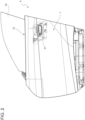
figure 2 is a view, from the outside of the motor vehicle, of the motor vehicle door offigure 1 on a much larger scale; -
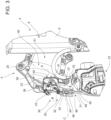
figure 3 is a perspective view, from the inside of the motor vehicle, on a further enlarged scale and according to a first visual angle, of first components of the door offigures 1 and2 , with parts removed for greater clarity; -
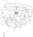
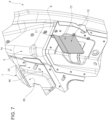
figure 4 is a perspective view, on a larger scale, from the inside of the motor vehicle and according to a different visual angle, of second components of the door offigures 1 and2 , with parts removed for greater clarity; -
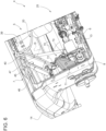
figure 5 is a view, from the inside of the motor vehicle, of the door offigure 1 , on a much larger scale and with parts removed for greater clarity; -
figure 6 is a cross section along line VI-VI offigure 5 ; and -
figures 7 and8 show second components of a second and third embodiment, respectively, of the door offigures 1 to 6 , with parts removed for greater clarity. - With reference to
figure 1 , number 1 indicates a motor vehicle. - More in detail, the motor vehicle 1 comprises a
body 2 delimiting apassenger compartment 3, a pair ofdoors 4 hinged to thebody 2 and aroof 35. - Furthermore, it is possible to define:
- a longitudinal axis X integral to the motor vehicle 1, which, in use, is horizontal and parallel to a normal travel direction of the motor vehicle 1;
- a transverse axis X integral to the vehicle 1, which, in use, is horizontal and orthogonal to the axis X; and
- an axis Z integral to the vehicle 1, which, in use, is vertical and orthogonal to the axes X, Y.
- Hereinafter, reference will be made to a
single door 4, thedoors 4 being substantially identical to one another. - Each
door 4 is movable (Figures 1 and2 ) between: - a closing position, in which it cooperates with the
body 2 and theroof 35 to delimit thepassenger compartment 3, so as to prevent access to/exit from thepassenger compartment 3 itself; and - an opening position, in which it allows access to and exit from the
passenger compartment 3. - Furthermore, expressions such as "above", "under", "in front of", "behind" and others similar to them are used with reference to normal driving conditions of the motor vehicle 1.
- The
door 4 basically comprises (Figures 3 a 6): - a
skeleton 5 defining awall 7 delimiting thedoor 4 on the outside of thepassenger compartment 3 and apillar 8 bent from oneend 14 of thewall 7 towards the inside of thebody 2; and - a
panel 6 defining awall 9 delimiting thedoor 4 on the inside of thepassenger compartment 3 and arranged so as to cover theskeleton 5. - The
skeleton 5 and thepanel 6 define acompartment 13 between them. - The
door 4 further comprises awindow 10 sliding relative to thepanel 6 and to theskeleton 5 through aslit 12 of theskeleton 5. - In particular, the
window 10 can slide relative to thepanel 6 between: - a lowered position, in which it is housed in the
compartment 13 frees anopening 11; and - a lifted position, in which it comes out of the
compartment 13 until it engages the opening 11. - Below is a description of the left
front door 4 of the motor vehicle 1, namely the one located on the driver's side. - The
door 4 further comprises: - a handle 21 (
Figures 1 and2 ) articulated with respect to thewall 7 on the outside of thebody 2 so that it can be gripped by a driver; - a support body 20 (
Figures 3 to 6 ) defined by theskeleton 5; and - a
ratchet 22, which is supported by thesupport body 20 so as to rotate around an axis A thereof and provided with an axial end notch located under thehandle 21 and capable of being operated by the driver by means of a key. - The
door 4 further comprises: - an
arm 23 fixed to thesupport body 20 and supporting anend 26 of theratchet 22 opposite the notch in a rotary manner; and - a
lever 24 hinged to theratchet 22 around the axis A. - The
door 4 further comprises a lock 25 (only schematically shown) located inside thecompartment 13, which is known and described below only insofar as it is relevant for the understanding of the invention. - The
lock 25 comprises, in turn: - a closing mechanism (not shown), which is elastically loaded towards an open configuration, in which it is disengaged from a striker (not shown) carried by the
body 2 so as to hold thedoor 4 in the open position, and which can be moved, following the slamming of thedoor 4, to a closed configuration, in which it is coupled to the striker and prevents thedoor 4 from moving from the closed position to the open position; and - an opening mechanism (not shown), which can be operated to determine the movement of the closing mechanism from the open configuration to the closed configuration.
- The
door 4 further comprises a microswitch (not shown), which can be operated by thehandle 21 to generate a control signal, which determines the activation of the opening mechanism and causes the opening mechanism of thelock 25 to shift from the closed configuration to the open configuration. - The
lock 25 further comprises an electric back-up system (not shown) and a mechanical back-up system 30 (Figures 3 to 6 ) able to allow the opening mechanism to be operated in case the microswitch is not electrically powered, for example due to the fact that the battery of the motor vehicle 1 is momentarily low. - The electric back-up system basically comprises a capacitive diode, which ensures a limited number of transitions of the opening mechanism from the closed configuration to the open configuration, even in the absence of an electrical power supply.
- The mechanical back-up
system 30 comprises, in turn, aBowden cable 31, which can be operated by theratchet 22 and is connected to the opening mechanism so as to cause it to shift from the closed configuration to the open configuration. - The
Bowden cable 31 comprises, in turn, a pair of axial ends 32, 33. - The
Bowden cable 31 further comprises aportion 34 ending in theend 32, opposite theend 33 and extending along an axis C orthogonal to the axis A (Figure 3 ). - The
end 32 is connected to theratchet 22 through thelever 24 and theend 33 is connected to the opening mechanism. - The
lever 24 is hinged to theratchet 22 around the axis A and to theend 32 around an axis B parallel to the axis A (Figure 3 ). - To sum up, the rotation of the
ratchet 22 determined by the use of the key causes the rotation of thelever 24 around the axis A and the consequent pulling of theBowden cable 31 along the axis C as well as the shift of the opening mechanism from the closed configuration to the open configuration. - The
support body 20 is fixed to thepanel 6 and is crossed by theratchet 22 and by theportion 34 of theBowden cable 31. - More in detail, the
support body 20 comprises (Figures 3 to 6 ): - a
wall 40 defining aconcave seat 39, open towards and having a contour contiguous with thewall 6; - a
cylindrical wall 41, adjacent to thewall 40 and coaxially crossed, with a clearance, by theratchet 22; and - a
seat 45 housing theportion 34 of theBowden cable 31 and a part of thelever 24 adjacent to the axis B. - More in detail, the notch of the
ratchet 22 faces the inside of theseat 39. - The
seat 45 is delimited by a pair ofwalls support body 20, which are parallel and spaced apart from one another. - The
walls Figure 6 ) orthogonal to the axes A, B, C. - The
wall 47 extends from thewall 41 and thewall 46 is joined to thewall 41 by awall 49 orthogonal to thewalls - The
wall 46 is located on the side of thewall 6 and thewall 47 is located on the side of thewall 7. More in particular, thewall 47 is interposed between thewall 46 and thepanel 6. - The
support body 20 further comprises awall 49 extending orthogonally to thewalls support element 48 of theBowden cable 31 visible inFigure 3 . - The
support body 20 defines: - a
first portion 50 comprising thewall 40, theratchet 22, thewalls seats - a
second portion 51 comprising the remaining part of thesupport body 20. - The
portions door 4 is in a normal operating condition. - Hereinafter and in the claims attached hereto, the expression "normal operating condition" means a condition in which the
door 4 has not suffered any side impact and the motor vehicle 1 is fully operational. - Advantageously, the
support body 20 comprises a preferential breaking area 60 (Figure 3 ) designed to break due to a predetermined load in case of impact of thedoor 4, so as to determine the separation of theportions - In this way, in case of impact, the
ratchet 22 and theBowden cable 31 are separated from thesecond portion 51 of thesupport body 20. - More in detail, the
area 60 is shaped like an open line, a curved open line in the case shown herein, surrounding theratchet 22 and theBowden cable 31. - The
area 60 further defines a weakening of thesupport body 20. In particular, the thickness of thearea 60 is smaller than the thickness of theportions - The
door 4 further comprises a bracket 70 (Figures 4 to 6 ) fixed to thepillar 8, extending inside thecompartment 13 and designed to strike against theportion 50 during the impact, so as to facilitate the separation between theportions area 60. - More in detail, the
bracket 70 strikes against thewall 47 of thesupport body 20 during the impact. - In the embodiment shown in
figure 6 , thebracket 70 has a cross section with a triangular shape. - The
bracket 70 comprises, in turn, (Figure 6 ): - a
wall 71 fixed to thepillar 8; - a
wall 72 defining a striking surface for thewall 47 of thesupport body 20; and - a
wall 73 interposed between thewalls - In particular, the
wall 72 is orthogonal to thewall 71 and thewall 73 is inclined relative to thewall 72. - The operation of the
door 4 is described starting from a condition of normal operation and from the closing position of thedoor 4. - In this condition, the closing mechanism of the
lock 25 is in the closed configuration and theportions support body 20 are integral to one another. - The
door 4 can normally be moved to the opening position by acting upon thehandle 21 so as to generate, through the microswitch, the control signal that determines the activation of the opening mechanism and the consequent shift of thelock 25 from the closed configuration to the open configuration. - In case of absence of supply of power to the microswitch, the opening mechanism can be operated by means of the capacitive diode or by means of the mechanical back-up
system 30 by inserting and turning the key in the notch of theratchet 22. - The rotation of the
ratchet 22 around the axis A determines the pulling of theBowden cable 31 along the axis C and the consequent activation of the opening mechanism. - In the event of a side impact of the
door 4, thesupport body 20 breaks in thearea 60 and thewall 47 of theseat 45 interacts with thebracket 70. - Consequently, the
portion 50 with theratchet 22 and theseat 45 housing theportion 34 of theBowden cable 31 gets separated from theportion 51. - Hence, the
portion 50 substantially remains in the position prior to the impact, whereas theportion 51 is pushed towards thewall 7 of thedoor 4. -
Figure 7 shows a door 4' according to a second embodiment of the invention. - The door 4' is similar to the
door 4 and will be described below only to the extent that it differs from the latter; equal or equivalent parts of thedoors 4, 4' will be indicated, when possible, with the same reference numbers. - More in detail, the bracket 70' of the door 4' differs from the
bracket 70 of thedoor 4 in that it does not comprise thewall 73, due to the fact that the wall 71' has a smaller surface than the wall 72'. The wall 72' further projects from an end edge of the wall 71' located on the side of thepanel 6. - The operation of the motor door 4' is completely similar to the one of the
door 4 and, therefore, it will not be described in detail. -
Figure 8 shows adoor 4" according to a third embodiment of the invention. - The
door 4" is similar to the door 4' and will be described below only to the extent that it differs from the latter; equal or equivalent parts of thedoors 4', 4" will be indicated, when possible, with the same reference numbers. - More in detail, the
bracket 70" of thedoor 4" differs from the bracket 70' of the door 4' in that thewall 72" projects from an end edge of the wall 71' located on the side of thewall 7. - The features of the
door - In particular, the
support body 20 breaks in thepreferential breaking area 60 in case of a side impact of thedoor 4. Consequently, theportion 50 comprising theratchet 22 and theBowden cable 31 gets separated from theportion 51. - Consequently, the
portion 50 with theratchet 22 and theseat 45 housing theportion 34 of theBowden cable 31 gets separated from theportion 51. - Hence, the
portion 50 substantially remains in the position prior to the impact, whereas theportion 51 is pushed towards thewall 7 of thedoor - This avoids the risk that the
walls seat 45 collide with further components housed in thecompartment 7, resulting in damage. - Consequently, the risk of accidental pulling of the
Bowden cable 31 and of any consequent accidental shift of the closing mechanism from the closed configuration to the open configuration is avoided. - The interaction of the
wall 47 with thebracket 70, 70', 70'' helps make the separation of theportion 51 from theportion 50 repeatable and controlled. - Finally, the
door
Claims (10)
- A door (4, 4', 4") for a motor vehicle (1) comprising:- a lock (25) available in a closed configuration, in which it prevents said door (4, 4', 4") from shifting from a closed position to an open position, and in an open configuration, in which it allows said door (4, 4', 4") to shift from said closed position to said open position; said door (4, 4', 4") allowing, in use, access to a passenger compartment (3) of said motor vehicle (1) in said open position and forbidding in use, access to said passenger compartment (3) in said closed position;- a support body (20) comprising, in turn, a first portion (50) and a second portion (51), which are integral to one another, when said door (4, 4', 4") is, in use, in a normal operating condition;- a ratchet (22) supported by said first portion (50) of said support body (20) and capable of being operated to determine the shifting of said lock (25) from said closed configuration to said open configuration; and- a Bowden cable (31), which is interposed between said ratchet (22) and said lock (25), can be operated by said ratchet (22) and is at least partly housed in a first seat (45) defined by said first portion (50) of said support body (20);characterized in that said support body (20) comprises a preferential breaking area (60) designed to break, in use, due a predetermined load in case of impact of said door (4, 4', 4''), so as to determine the separation of said first portion (50) carrying said Bowden cable (31) and said ratchet (22) from said second portion (51) of the support body (20).
- The door according to claim 1, characterized in that said preferential area (60) is shaped like an open curved line.
- The door according to claim 1 or 2, characterized in that said preferential area (60) has a first thickness, which is smaller than a second thickness of said first and second portion (50, 51).
- The door according to any one of the preceding claims, characterized in that it further comprises a handle (21), which can be operated to determine the shifting of said lock (25) from said closed configuration to said open configuration;
said ratchet (22) being capable of being operated by a key;
said support body (20) comprising a first concave wall (40) defining a second seat (39) housing said handle (21) supported by said support body (20) and said ratchet (22). - The door according to any one of the preceding claims, comprising:- a skeleton (5) defining a second wall (7) of said door (4, 4', 4") and a pillar (8) transverse to said first wall (7);- a panel (6) defining a third wall (9) opposite said first wall (7); and- a compartment (13) defined between said skeleton (5) and said panel (6) and partly housing said support body (20) ;said door (4, 4', 4") further comprising a bracket (70, 70', 70") fixed to said pillar (8), extending inside said compartment (13) and designed to strike against said first portion (50) of said support body (20) in use, during said impact.
- The door according to any one of the claims 4 or 5, characterized in that said first portion (50) of said support body (20) comprises, in turn:- a fourth wall (41) contiguous with said first wall (40) and housing said ratchet (22);- at least a fifth wall (46, 47) projecting from one of said first and fourth walls (40, 41) and delimiting said first seat (45) housing an end (32) of said Bowden cable (31) opposite said lock (25) and arranged on the side of said ratchet (22);said fifth wall (46, 47) being spaced apart from said bracket (70, 70', 70'') in said normal operating condition of said door (4) and striking against said bracket (70, 70', 70''), in use, during said impact.
- The door according to claim 6, characterized in that said bracket (70, 70', 70'') comprises, in turn: a sixth wall (71, 71', 71'') fixed to said pillar (8) and a seventh wall (72, 72', 72") defining, in use, a striking surface for said fifth wall (46, 47) during said impact.
- The door according to claim 7, characterized in that it comprises an eighth wall (73) interposed between said sixth and seventh walls (71, 72); said eighth wall (73) extending crosswise to said sixth wall (71) and to said seventh wall (72).
- The door according to claim 7, characterized in that said sixth and seventh walls (71', 72'; 71'' , 72") are contiguous with, adjacent and transverse to one another.
- A motor vehicle comprising:- a body (2) defining a passenger compartment (3); and- a door (4, 4', 4'') according to any one of the preceding claims.
Applications Claiming Priority (1)
| Application Number | Priority Date | Filing Date | Title |
|---|---|---|---|
| IT202300018348 | 2023-09-07 |
Publications (2)
| Publication Number | Publication Date |
|---|---|
| EP4520562A1 true EP4520562A1 (en) | 2025-03-12 |
| EP4520562B1 EP4520562B1 (en) | 2026-03-18 |
Family
ID=88689850
Family Applications (1)
| Application Number | Title | Priority Date | Filing Date |
|---|---|---|---|
| EP24198627.2A Active EP4520562B1 (en) | 2023-09-07 | 2024-09-05 | Door for a motor vehicle |
Country Status (2)
| Country | Link |
|---|---|
| US (1) | US12460452B2 (en) |
| EP (1) | EP4520562B1 (en) |
Citations (2)
| Publication number | Priority date | Publication date | Assignee | Title |
|---|---|---|---|---|
| US20100109350A1 (en) * | 2008-11-05 | 2010-05-06 | Gm Global Technology Operations, Inc. | Vehicle side door assembly |
| JP6612625B2 (en) * | 2016-01-12 | 2019-11-27 | 本田技研工業株式会社 | Car door structure |
Family Cites Families (7)
| Publication number | Priority date | Publication date | Assignee | Title |
|---|---|---|---|---|
| MX2012013366A (en) * | 2010-06-08 | 2013-01-24 | Nissan Motor | Vehicle door structure. |
| US10316551B2 (en) * | 2014-01-10 | 2019-06-11 | Inteva Products, Llc | Apparatus and method for preventing undesired latch release |
| US10676970B2 (en) * | 2017-04-05 | 2020-06-09 | Toyota Motor Engineering & Manufacturing North America, Inc. | Protection block for vehicle door lock |
| US10914101B2 (en) * | 2017-11-01 | 2021-02-09 | Toyota Motor Engineering & Manufacturing North America, Inc. | Door latch assemblies for vehicles including latch release lever blocking structures |
| US11660939B2 (en) * | 2021-09-13 | 2023-05-30 | Nissan North America, Inc. | Vehicle body structure |
| US11541732B1 (en) * | 2021-09-13 | 2023-01-03 | Nissan North America, Inc. | Vehicle door assembly |
| US12172501B2 (en) * | 2022-04-22 | 2024-12-24 | Nissan North America, Inc. | Vehicle door assembly |
-
2024
- 2024-08-30 US US18/820,942 patent/US12460452B2/en active Active
- 2024-09-05 EP EP24198627.2A patent/EP4520562B1/en active Active
Patent Citations (2)
| Publication number | Priority date | Publication date | Assignee | Title |
|---|---|---|---|---|
| US20100109350A1 (en) * | 2008-11-05 | 2010-05-06 | Gm Global Technology Operations, Inc. | Vehicle side door assembly |
| JP6612625B2 (en) * | 2016-01-12 | 2019-11-27 | 本田技研工業株式会社 | Car door structure |
Also Published As
| Publication number | Publication date |
|---|---|
| US12460452B2 (en) | 2025-11-04 |
| EP4520562B1 (en) | 2026-03-18 |
| US20250084671A1 (en) | 2025-03-13 |
Similar Documents
| Publication | Publication Date | Title |
|---|---|---|
| US6676190B2 (en) | Headliner mounted power liftgate drive mechanism | |
| US11598128B2 (en) | Flush handle device for controlling vehicle door latch | |
| EP0153743B1 (en) | Vehicular air flow control device with variable angle air flow control fin | |
| US11608659B2 (en) | Vehicle door assembly | |
| GB2369394A (en) | Rear door assembly for motor vehicle | |
| EP1748130A2 (en) | Vehicle door latch | |
| US20250163734A1 (en) | Vehicle door with an extendable handle | |
| US20250146335A1 (en) | Vehicle Door for a Motor Vehicle and Method for Operating Such a Vehicle Door | |
| US11660939B2 (en) | Vehicle body structure | |
| WO2008047175A1 (en) | Vehicle with improved double leafed door system | |
| GB2475962A (en) | A handle module with shield for a vehicle door | |
| EP4520562A1 (en) | Door for a motor vehicle | |
| EP1276949B1 (en) | Headliner mounted power liftgate drive mechanism | |
| JP5428418B2 (en) | Vehicle door opening and closing device | |
| US11541732B1 (en) | Vehicle door assembly | |
| US12024937B2 (en) | Partial-opening device for a motor-vehicle door element | |
| DE102022104044B4 (en) | Vehicle door for a motor vehicle and method for operating such a vehicle door | |
| EP2203616B1 (en) | Locking device for the door of a motor vehicle | |
| US11746571B2 (en) | Ratchet unit for motor vehicle flaps or motor vehicle doors | |
| US20050236866A1 (en) | Sliding door and vehicle with a sliding door | |
| CN112154248B (en) | Emergency actuating device | |
| JP4395571B2 (en) | Vehicle door lock striker structure | |
| EP1803877A2 (en) | Door handle structure requiring a smaller space for arranging a mechanism for releasing a door latch | |
| JP3835407B2 (en) | Automotive door | |
| JP2013107556A (en) | Sliding door structure |
Legal Events
| Date | Code | Title | Description |
|---|---|---|---|
| PUAI | Public reference made under article 153(3) epc to a published international application that has entered the european phase |
Free format text: ORIGINAL CODE: 0009012 |
|
| STAA | Information on the status of an ep patent application or granted ep patent |
Free format text: STATUS: THE APPLICATION HAS BEEN PUBLISHED |
|
| AK | Designated contracting states |
Kind code of ref document: A1 Designated state(s): AL AT BE BG CH CY CZ DE DK EE ES FI FR GB GR HR HU IE IS IT LI LT LU LV MC ME MK MT NL NO PL PT RO RS SE SI SK SM TR |
|
| STAA | Information on the status of an ep patent application or granted ep patent |
Free format text: STATUS: REQUEST FOR EXAMINATION WAS MADE |
|
| GRAP | Despatch of communication of intention to grant a patent |
Free format text: ORIGINAL CODE: EPIDOSNIGR1 |
|
| STAA | Information on the status of an ep patent application or granted ep patent |
Free format text: STATUS: GRANT OF PATENT IS INTENDED |
|
| 17P | Request for examination filed |
Effective date: 20250910 |
|
| RIC1 | Information provided on ipc code assigned before grant |
Ipc: B60J 5/04 20060101AFI20250911BHEP Ipc: E05B 17/00 20060101ALI20250911BHEP Ipc: E05B 77/04 20140101ALI20250911BHEP Ipc: E05B 79/20 20140101ALI20250911BHEP Ipc: E05B 79/22 20140101ALI20250911BHEP |
|
| INTG | Intention to grant announced |
Effective date: 20251009 |
|
| GRAS | Grant fee paid |
Free format text: ORIGINAL CODE: EPIDOSNIGR3 |
|
| GRAA | (expected) grant |
Free format text: ORIGINAL CODE: 0009210 |
|
| STAA | Information on the status of an ep patent application or granted ep patent |
Free format text: STATUS: THE PATENT HAS BEEN GRANTED |
|
| AK | Designated contracting states |
Kind code of ref document: B1 Designated state(s): AL AT BE BG CH CY CZ DE DK EE ES FI FR GB GR HR HU IE IS IT LI LT LU LV MC ME MK MT NL NO PL PT RO RS SE SI SK SM TR |
|
| REG | Reference to a national code |
Ref country code: CH Ref legal event code: F10 Free format text: ST27 STATUS EVENT CODE: U-0-0-F10-F00 (AS PROVIDED BY THE NATIONAL OFFICE) Effective date: 20260318 Ref country code: GB Ref legal event code: FG4D |
|
| REG | Reference to a national code |
Ref country code: IE Ref legal event code: FG4D |
|
| REG | Reference to a national code |
Ref country code: DE Ref legal event code: R096 Ref document number: 602024003277 Country of ref document: DE |