EP4518569A2 - Extraktion von ethercat-datagrammen aus einem ethercat-rahmen - Google Patents
Extraktion von ethercat-datagrammen aus einem ethercat-rahmen Download PDFInfo
- Publication number
- EP4518569A2 EP4518569A2 EP25151135.8A EP25151135A EP4518569A2 EP 4518569 A2 EP4518569 A2 EP 4518569A2 EP 25151135 A EP25151135 A EP 25151135A EP 4518569 A2 EP4518569 A2 EP 4518569A2
- Authority
- EP
- European Patent Office
- Prior art keywords
- ethercat
- ethernet
- datagram
- automation technology
- control automation
- Prior art date
- Legal status (The legal status is an assumption and is not a legal conclusion. Google has not performed a legal analysis and makes no representation as to the accuracy of the status listed.)
- Pending
Links
Images



Classifications
-
- H—ELECTRICITY
- H04—ELECTRIC COMMUNICATION TECHNIQUE
- H04L—TRANSMISSION OF DIGITAL INFORMATION, e.g. TELEGRAPHIC COMMUNICATION
- H04L69/00—Network arrangements, protocols or services independent of the application payload and not provided for in the other groups of this subclass
- H04L69/22—Parsing or analysis of headers
-
- H—ELECTRICITY
- H04—ELECTRIC COMMUNICATION TECHNIQUE
- H04L—TRANSMISSION OF DIGITAL INFORMATION, e.g. TELEGRAPHIC COMMUNICATION
- H04L12/00—Data switching networks
- H04L12/28—Data switching networks characterised by path configuration, e.g. LAN [Local Area Networks] or WAN [Wide Area Networks]
- H04L12/40—Bus networks
- H04L12/40006—Architecture of a communication node
-
- H—ELECTRICITY
- H04—ELECTRIC COMMUNICATION TECHNIQUE
- H04L—TRANSMISSION OF DIGITAL INFORMATION, e.g. TELEGRAPHIC COMMUNICATION
- H04L12/00—Data switching networks
- H04L12/02—Details
- H04L12/16—Arrangements for providing special services to substations
- H04L12/18—Arrangements for providing special services to substations for broadcast or conference, e.g. multicast
- H04L12/189—Arrangements for providing special services to substations for broadcast or conference, e.g. multicast in combination with wireless systems
-
- H—ELECTRICITY
- H04—ELECTRIC COMMUNICATION TECHNIQUE
- H04W—WIRELESS COMMUNICATION NETWORKS
- H04W80/00—Wireless network protocols or protocol adaptations to wireless operation
- H04W80/02—Data link layer protocols
-
- G—PHYSICS
- G05—CONTROLLING; REGULATING
- G05B—CONTROL OR REGULATING SYSTEMS IN GENERAL; FUNCTIONAL ELEMENTS OF SUCH SYSTEMS; MONITORING OR TESTING ARRANGEMENTS FOR SUCH SYSTEMS OR ELEMENTS
- G05B19/00—Program-control systems
- G05B19/02—Program-control systems electric
- G05B19/04—Program control other than numerical control, i.e. in sequence controllers or logic controllers
- G05B19/042—Program control other than numerical control, i.e. in sequence controllers or logic controllers using digital processors
- G05B19/0426—Programming the control sequence
-
- H—ELECTRICITY
- H04—ELECTRIC COMMUNICATION TECHNIQUE
- H04L—TRANSMISSION OF DIGITAL INFORMATION, e.g. TELEGRAPHIC COMMUNICATION
- H04L12/00—Data switching networks
- H04L12/28—Data switching networks characterised by path configuration, e.g. LAN [Local Area Networks] or WAN [Wide Area Networks]
- H04L12/40—Bus networks
-
- H—ELECTRICITY
- H04—ELECTRIC COMMUNICATION TECHNIQUE
- H04L—TRANSMISSION OF DIGITAL INFORMATION, e.g. TELEGRAPHIC COMMUNICATION
- H04L12/00—Data switching networks
- H04L12/28—Data switching networks characterised by path configuration, e.g. LAN [Local Area Networks] or WAN [Wide Area Networks]
- H04L12/40—Bus networks
- H04L2012/4026—Bus for use in automation systems
-
- H—ELECTRICITY
- H04—ELECTRIC COMMUNICATION TECHNIQUE
- H04W—WIRELESS COMMUNICATION NETWORKS
- H04W4/00—Services specially adapted for wireless communication networks; Facilities therefor
- H04W4/70—Services for machine-to-machine communication [M2M] or machine type communication [MTC]
Definitions
- the subject matter disclosed herein relates generally to wireless communications and more particularly relates to extracting EtherCAT datagrams from an EtherCAT frame.
- EtherCAT may be used for communicating information.
- the method includes receiving an Ethernet for control automation technology frame. In various embodiments, the method includes determining a first Ethernet for control automation technology datagram in the Ethernet for control automation technology frame for a first device and a second Ethernet for control automation technology datagram in the Ethernet for control automation technology frame for a second device. In certain embodiments, the method includes extracting the first Ethernet for control automation technology datagram from the Ethernet for control automation technology frame to result in an extracted first Ethernet for control automation technology datagram and the second Ethernet for control automation technology datagram from the Ethernet for control automation technology frame to result in an extracted second Ethernet for control automation technology datagram. In some embodiments, the method includes transmitting the extracted first Ethernet for control automation technology datagram directly to the first device. In various embodiments, the method includes transmitting the extracted second Ethernet for control automation technology datagram directly to the second device.
- An apparatus for extracting EtherCAT datagrams from an EtherCAT frame includes a receiver that receives an Ethernet for control automation technology frame.
- the apparatus includes a processor that: determines a first Ethernet for control automation technology datagram in the Ethernet for control automation technology frame for a first device and a second Ethernet for control automation technology datagram in the Ethernet for control automation technology frame for a second device; and extracts the first Ethernet for control automation technology datagram from the Ethernet for control automation technology frame to result in an extracted first Ethernet for control automation technology datagram and the second Ethernet for control automation technology datagram from the Ethernet for control automation technology frame to result in an extracted second Ethernet for control automation technology datagram.
- the apparatus includes a transmitter that: transmits the extracted first Ethernet for control automation technology datagram directly to the first device; and transmits the extracted second Ethernet for control automation technology datagram directly to the second device.
- One method for forming an EtherCAT frame from an EtherCAT datagram includes receiving an Ethernet for control automation technology datagram. In some embodiments, the method includes receiving common header information corresponding to the Ethernet for control automation technology datagram. In certain embodiments, the method includes forming an Ethernet for control automation technology frame based on the Ethernet for control automation technology datagram.
- An apparatus for forming an EtherCAT frame from an EtherCAT datagram includes a receiver that: receives an Ethernet for control automation technology datagram; and receives common header information corresponding to the Ethernet for control automation technology datagram.
- the apparatus includes a processor that forms an Ethernet for control automation technology frame based on the Ethernet for control automation technology datagram.
- embodiments may be embodied as a system, apparatus, method, or program product. Accordingly, embodiments may take the form of an entirely hardware embodiment, an entirely software embodiment (including firmware, resident software, micro-code, etc.) or an embodiment combining software and hardware aspects that may all generally be referred to herein as a "circuit," "module” or “system.” Furthermore, embodiments may take the form of a program product embodied in one or more computer readable storage devices storing machine readable code, computer readable code, and/or program code, referred hereafter as code. The storage devices may be tangible, non-transitory, and/or non-transmission. The storage devices may not embody signals. In a certain embodiment, the storage devices only employ signals for accessing code.
- modules may be implemented as a hardware circuit comprising custom very-large-scale integration ("VLSI") circuits or gate arrays, off-the-shelf semiconductors such as logic chips, transistors, or other discrete components.
- VLSI very-large-scale integration
- a module may also be implemented in programmable hardware devices such as field programmable gate arrays, programmable array logic, programmable logic devices or the like.
- Modules may also be implemented in code and/or software for execution by various types of processors.
- An identified module of code may, for instance, include one or more physical or logical blocks of executable code which may, for instance, be organized as an object, procedure, or function. Nevertheless, the executables of an identified module need not be physically located together, but may include disparate instructions stored in different locations which, when joined logically together, include the module and achieve the stated purpose for the module.
- a module of code may be a single instruction, or many instructions, and may even be distributed over several different code segments, among different programs, and across several memory devices.
- operational data may be identified and illustrated herein within modules, and may be embodied in any suitable form and organized within any suitable type of data structure. The operational data may be collected as a single data set, or may be distributed over different locations including over different computer readable storage devices.
- the software portions are stored on one or more computer readable storage devices.
- the computer readable medium may be a computer readable storage medium.
- the computer readable storage medium may be a storage device storing the code.
- the storage device may be, for example, but not limited to, an electronic, magnetic, optical, electromagnetic, infrared, holographic, micromechanical, or semiconductor system, apparatus, or device, or any suitable combination of the foregoing.
- a storage device More specific examples (a non-exhaustive list) of the storage device would include the following: an electrical connection having one or more wires, a portable computer diskette, a hard disk, a random access memory (“RAM”), a read-only memory (“ROM”), an erasable programmable read-only memory (“EPROM” or Flash memory), a portable compact disc read-only memory (“CD-ROM”), an optical storage device, a magnetic storage device, or any suitable combination of the foregoing.
- a computer readable storage medium may be any tangible medium that can contain, or store a program for use by or in connection with an instruction execution system, apparatus, or device.
- Code for carrying out operations for embodiments may be any number of lines and may be written in any combination of one or more programming languages including an object oriented programming language such as Python, Ruby, Java, Smalltalk, C++, or the like, and conventional procedural programming languages, such as the "C" programming language, or the like, and/or machine languages such as assembly languages.
- the code may execute entirely on the user's computer, partly on the user's computer, as a stand-alone software package, partly on the user's computer and partly on a remote computer or entirely on the remote computer or server.
- the remote computer may be connected to the user's computer through any type of network, including a local area network (“LAN”) or a wide area network (“WAN”), or the connection may be made to an external computer (for example, through the Internet using an Internet Service Provider).
- LAN local area network
- WAN wide area network
- Internet Service Provider an Internet Service Provider
- the code may also be stored in a storage device that can direct a computer, other programmable data processing apparatus, or other devices to function in a particular manner, such that the instructions stored in the storage device produce an article of manufacture including instructions which implement the function/act specified in the schematic flowchart diagrams and/or schematic block diagrams block or blocks.
- the code may also be loaded onto a computer, other programmable data processing apparatus, or other devices to cause a series of operational steps to be performed on the computer, other programmable apparatus or other devices to produce a computer implemented process such that the code which execute on the computer or other programmable apparatus provide processes for implementing the functions/acts specified in the flowchart and/or block diagram block or blocks.
- each block in the schematic flowchart diagrams and/or schematic block diagrams may represent a module, segment, or portion of code, which includes one or more executable instructions of the code for implementing the specified logical function(s).
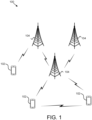
- Figure 1 depicts an embodiment of a wireless communication system 100 for extracting EtherCAT datagrams from an EtherCAT frame.
- the wireless communication system 100 includes remote units 102, and network units 104. Even though a specific number of remote units 102 and network units 104 are depicted in Figure 1 , one of skill in the art will recognize that any number of remote units 102 and network units 104 may be included in the wireless communication system 100.
- the remote units 102 may include computing devices, such as desktop computers, laptop computers, personal digital assistants ("PDAs"), tablet computers, smart phones, smart televisions (e.g., televisions connected to the Internet), set-top boxes, game consoles, security systems (including security cameras), vehicle on-board computers, network devices (e.g., routers, switches, modems), IoT devices, or the like.
- the remote units 102 include wearable devices, such as smart watches, fitness bands, optical head-mounted displays, or the like.
- the remote units 102 may be referred to as subscriber units, mobiles, mobile stations, users, terminals, mobile terminals, fixed terminals, subscriber stations, UE, user terminals, a device, or by other terminology used in the art.
- the remote units 102 may communicate directly with one or more of the network units 104 via UL communication signals.
- the remote units 102 may communicate directly with other remote units 102 via SL communication.
- the network units 104 may be distributed over a geographic region.
- a network unit 104 may also be referred to as an access point, an access terminal, a base, a base station, a Node-B, an eNB, a gNB, a Home Node-B, a relay node, a device, a network device, or by any other terminology used in the art.
- the network units 104 are generally part of a radio access network that includes one or more controllers communicably coupled to one or more corresponding network units 104.
- the radio access network is generally communicably coupled to one or more core networks, which may be coupled to other networks, like the Internet and public switched telephone networks, among other networks.
- a network unit 104 may include one or more of the following network components a gNB, a NG-RAN node, a RAN node, a core network, an MME, an HSS, an SCEF, an AMF, an SMF, an NEF, a PCF, a UDR, a UPF, and/or a UDM.
- the wireless communication system 100 is compliant with the LTE of the 3GPP protocol, wherein the network unit 104 transmits using an OFDM modulation scheme on the DL and the remote units 102 transmit on the UL using a SC-FDMA scheme or an OFDM scheme. More generally, however, the wireless communication system 100 may implement some other open or proprietary communication protocol, for example, WiMAX, among other protocols.
- WiMAX wireless personal area network
- the network units 104 may serve a number of remote units 102 within a serving area, for example, a cell or a cell sector via a wireless communication link.
- the network units 104 transmit DL communication signals to serve the remote units 102 in the time, frequency, and/or spatial domain.
- a remote unit 102 may receive an Ethernet for control automation technology datagram. In some embodiments, the remote unit 102 may receive common header information corresponding to the Ethernet for control automation technology datagram. In certain embodiments, the remote unit 102 may form an Ethernet for control automation technology frame based on the Ethernet for control automation technology datagram. Accordingly, a remote unit 102 may be used for forming an EtherCAT frame from an EtherCAT datagram.
- a network unit 104 may receive an Ethernet for control automation technology frame. In various embodiments, the network unit 104 may determine a first Ethernet for control automation technology datagram in the Ethernet for control automation technology frame for a first device and a second Ethernet for control automation technology datagram in the Ethernet for control automation technology frame for a second device. In certain embodiments, the network unit 104 may extract the first Ethernet for control automation technology datagram from the Ethernet for control automation technology frame to result in an extracted first Ethernet for control automation technology datagram and the second Ethernet for control automation technology datagram from the Ethernet for control automation technology frame to result in an extracted second Ethernet for control automation technology datagram. In some embodiments, the network unit 104 may transmit the extracted first Ethernet for control automation technology datagram directly to the first device. In various embodiments, the network unit 104 may transmit the extracted second Ethernet for control automation technology datagram directly to the second device. Accordingly, a network unit 104 may be used for extracting EtherCAT datagrams from an EtherCAT frame.
- Figure 2 depicts one embodiment of an apparatus 200 that may be used for forming an EtherCAT frame from an EtherCAT datagram.
- the apparatus 200 includes one embodiment of the remote unit 102.
- the remote unit 102 may include a processor 202, a memory 204, an input device 206, a display 208, a transmitter 210, and a receiver 212.
- the input device 206 and the display 208 are combined into a single device, such as a touchscreen.
- the remote unit 102 may not include any input device 206 and/or display 208.
- the remote unit 102 may include one or more of the processor 202, the memory 204, the transmitter 210, and the receiver 212, and may not include the input device 206 and/or the display 208.
- the processor 202 may include any known controller capable of executing computer-readable instructions and/or capable of performing logical operations.
- the processor 202 may be a microcontroller, a microprocessor, a central processing unit ("CPU"), a graphics processing unit (“GPU”), an auxiliary processing unit, a field programmable gate array (“FPGA”), or similar programmable controller.
- the processor 202 executes instructions stored in the memory 204 to perform the methods and routines described herein.
- the processor 202 may form an EtherCAT frame based on an EtherCAT datagram.
- the processor 202 is communicatively coupled to the memory 204, the input device 206, the display 208, the transmitter 210, and the receiver 212.
- the memory 204 in one embodiment, is a computer readable storage medium.
- the memory 204 includes volatile computer storage media.
- the memory 204 may include a RAM, including dynamic RAM (“DRAM”), synchronous dynamic RAM (“SDRAM”), and/or static RAM (“SRAM”).
- the memory 204 includes non-volatile computer storage media.
- the memory 204 may include a hard disk drive, a flash memory, or any other suitable non-volatile computer storage device.
- the memory 204 includes both volatile and non-volatile computer storage media.
- the memory 204 stores data relating to network registration.
- the memory 204 also stores program code and related data, such as an operating system or other controller algorithms operating on the remote unit 102.
- the input device 206 may include any known computer input device including a touch panel, a button, a keyboard, a stylus, a microphone, or the like.
- the input device 206 may be integrated with the display 208, for example, as a touchscreen or similar touch-sensitive display.
- the input device 206 includes a touchscreen such that text may be input using a virtual keyboard displayed on the touchscreen and/or by handwriting on the touchscreen.
- the input device 206 includes two or more different devices, such as a keyboard and a touch panel.
- the display 208 may include any known electronically controllable display or display device.
- the display 208 may be designed to output visual, audible, and/or haptic signals.
- the display 208 includes an electronic display capable of outputting visual data to a user.
- the display 208 may include, but is not limited to, an LCD display, an LED display, an OLED display, a projector, or similar display device capable of outputting images, text, or the like to a user.
- the display 208 may include a wearable display such as a smart watch, smart glasses, a heads-up display, or the like.
- the display 208 may be a component of a smart phone, a personal digital assistant, a television, a table computer, a notebook (laptop) computer, a personal computer, a vehicle dashboard, or the like.
- the display 208 includes one or more speakers for producing sound.
- the display 208 may produce an audible alert or notification (e.g., a beep or chime).
- the display 208 includes one or more haptic devices for producing vibrations, motion, or other haptic feedback.
- all or portions of the display 208 may be integrated with the input device 206.
- the input device 206 and display 208 may form a touchscreen or similar touch-sensitive display.
- the display 208 may be located near the input device 206.
- the transmitter 210 is used to provide UL communication signals to the network unit 104 and the receiver 212 is used to receive DL communication signals from the network unit 104.
- the receiver 212 may: receive an EtherCAT datagram; and receive common header information corresponding to the EtherCAT datagram.
- the remote unit 102 may have any suitable number of transmitters 210 and receivers 212.
- the transmitter 210 and the receiver 212 may be any suitable type of transmitters and receivers.
- the transmitter 210 and the receiver 212 may be part of a transceiver.
- Figure 3 depicts one embodiment of an apparatus 300 that may be used for extracting EtherCAT datagrams from an EtherCAT frame.
- the apparatus 300 includes one embodiment of the network unit 104.
- the network unit 104 may include a processor 302, a memory 304, an input device 306, a display 308, a transmitter 310, and a receiver 312.
- the processor 302, the memory 304, the input device 306, the display 308, the transmitter 310, and the receiver 312 may be substantially similar to the processor 202, the memory 204, the input device 206, the display 208, the transmitter 210, and the receiver 212 of the remote unit 102, respectively.
- the receiver 312 receives an EtherCAT frame.
- the processor 302 determines a first EtherCAT datagram in the EtherCAT frame for a first device and a second EtherCAT datagram in the EtherCAT frame for a second device; and extracts the first EtherCAT datagram from the EtherCAT frame to result in an extracted first EtherCAT datagram and the second EtherCAT datagram from the EtherCAT frame to result in an extracted second EtherCAT datagram.
- the transmitter 310 transmits the extracted first EtherCAT datagram directly to the first device; and transmits the extracted second EtherCAT datagram directly to the second device.
- the network unit 104 may have any suitable number of transmitters 310 and receivers 312.
- the transmitter 310 and the receiver 312 may be any suitable type of transmitters and receivers.
- the transmitter 310 and the receiver 312 may be part of a transceiver.
- an Ethernet fieldbus may use fieldbus masters to send Ethernet packets to individual fieldbus slaves, or the fieldbus masters may broadcast to a group of fieldbus slaves.
- the Ethernet packets may take the form of a fieldbus packet encapsulated inside an IP packet such as UDP.
- the fieldbus master may wait for the fieldbus slaves to process the received data and respond to the fieldbus master via a response packet.
- Ethernet packets may be delayed by only a few nanoseconds by each fieldbus slave in the chain because the fieldbus slave reads and writes to the encapsulated datagram each time it is received. Accordingly, Ethernet packets are "processed on-the-fly.”
- each fieldbus slave extracts its own data packet from an Ethernet datagram addressed specifically to it, while simultaneously forwarding the frame to the next device in the chain.
- data to be returned to the EtherCAT master is inserted on-the-fly while the packet is processed by the fieldbus slave, as the Ethernet frame passes through the device.
- FIG. 4 is a schematic block diagram illustrating one embodiment of a system 400 that may use EtherCAT frames.
- the system 400 is a wireless system.
- the system 400 includes an EtherCAT master 402 (e.g., a network unit 104), a first UE 404 (e.g., a first remote unit 102), a second UE 406 (e.g., a second remote unit 102), and a third UE 408 (e.g., a third remote unit 102).
- the EtherCAT master 402 transmits 410 an EtherCAT frame to the first UE 404.
- the first UE 404 processes the EtherCAT frame to extract an EtherCAT datagram corresponding to the first UE 404, then inserts data to be returned to the EtherCAT master 402 into the EtherCAT datagram of the EtherCAT frame corresponding to the first UE 404.
- the first UE 404 then transmits 412 the revised EtherCAT frame to the second UE 406.
- the second UE 406 processes the revised EtherCAT frame to extract an EtherCAT datagram corresponding to the second UE 406, then inserts data to be returned to the EtherCAT master 402 into the EtherCAT datagram of the EtherCAT frame corresponding to the second UE 406.
- the second UE 406 then transmits 414 the revised EtherCAT frame to the third UE 408.
- the third UE 408 processes the revised EtherCAT frame to extract an EtherCAT datagram corresponding to the third UE 408, then inserts data to be returned to the EtherCAT master 402 into the EtherCAT datagram of the EtherCAT frame corresponding to the third UE 408.
- the third UE 408 then transmits 416 the revised EtherCAT frame to the EtherCAT master 402.
- latency may be added by the processing done by each of the first UE 404, the second UE 406, and the third UE 408. This may result in high latency and inefficient use of resources (e.g., insufficient use of bandwidth with the entire EtherCAT transmitted to each of the first UE 404, the second UE 406, and the third UE 408).
- FIG. 5 is a schematic block diagram illustrating one embodiment of an EtherCAT frame 500.
- the EtherCAT frame 500 includes an Ethernet header 502, an EtherCAT header 504, an EtherCAT telegram 506, and an FCS 508.
- FIG. 6 is a schematic block diagram illustrating one embodiment of the EtherCAT telegram 506.
- the EtherCAT telegram 506 includes a first datagram 602, a second datagram 604, a safety container 606, a third datagram 608, and an nth datagram 610.
- the EtherCAT telegram 506 may not include the safety container 606 and/or the EtherCAT telegram 506 may include fewer or more datagrams than illustrated.
- the EtherCAT telegram 506 may include up to 15 datagrams.
- Each datagram may include a header, data to be read and/or written, and/or a working counter.
- FIG. 7 is a schematic block diagram illustrating one embodiment of the safety container 606.
- the safety container 606 may include a command 702 ("CMD"), a first safe data 704, a first CRC 706 corresponding to the first safe data 704, a second safe data 708, a second CRC 710 corresponding to the second safe data 708, and a connection ID 712 ("Conn ID").
- CMD command 702
- first safe data 704 a first CRC 706 corresponding to the first safe data 704
- a second safe data 708 a second CRC 710 corresponding to the second safe data 708, and a connection ID 712 (“Conn ID").
- Conn ID connection ID
- the safety container 606 may include any suitable number of safe data and CRCs corresponding to the safe data.
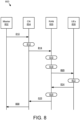
- FIG 8 is a schematic block diagram illustrating one embodiment of communications 800 in a system that uses EtherCAT frames. Communications 800 are illustrated between a master 802 (e.g., EtherCAT master), a CN 804 (e.g., UPF), a RAN 806 (e.g., eNB, gNB, BS, AP, NR, etc.), and UEs 808 (e.g., multiple UEs, multiple remote units 102, etc.). As may be appreciated, individual communications described herein may include one or more messages.
- a master 802 e.g., EtherCAT master
- CN 804 e.g., UPF
- a RAN 806 e.g., eNB, gNB, BS, AP, NR, etc.
- UEs 808 e.g., multiple UEs, multiple remote units 102, etc.
- individual communications described herein may include one or more messages.
- the master 802 transmits an EtherCAT frame.
- the CN 804 e.g., UPF marks the incoming EtherCAT frame from the master 802 with an Ethertype identifier ("Ethertype ID") and adds the EtherCAT frame to a QoS flow.
- Ethertype ID may be used to indicate that the EtherCAT frame received from the master 802 is an EtherCAT frame.
- the CN 804 transmits the EtherCAT frame with the Ethertype ID to the RAN 806 as part of a QoS flow.
- the RAN 806 e.g., SDAP entity in the RAN 806 TX path
- the RAN 806 reads 816 the Ethertype ID in the QoS flow (e.g., and the topology information) and identifies the incoming Ethernet packet as an EtherCAT frame.
- the RAN 806 sets up 818 an Ethernet profile and context information corresponding to the EtherCAT frame to parse the EtherCAT telegram of the EtherCAT frame. This enables the RAN 806 to read, extract, and/or process the information in the EtherCAT telegram.
- the RAN 806 may read the EtherCAT telegram and segment the EtherCAT telegram into multiple datagrams (e.g., SDAP PDU's). The RAN 806 may map the datagrams to different radio bearers. The RAN 806 may schedule the datagrams (which include a node specific header and data) for unicast transmission for transmission to corresponding UEs 808. Moreover, the RAN 806 may schedule common header information (e.g., EtherCAT header 504) required for all UEs 808 (e.g., nodes) for multicast transmission.
- EtherCAT header 504 common header information required for all UEs 808 (e.g., nodes) for multicast transmission.
- the RAN 806 extracts the Ethertype ID (e.g., and the topology) from a QoS flow, reads the Ethertype ID (e.g., and the topology), determines whether the Ethertype ID matches an ID that corresponds to an EtherCAT frame structure (or any field bus protocol that does on the fly processing of an Ethernet frame), loads relevant profile information of the frame structure corresponding to the Ethertype ID, and parses the Ethernet packet according to the profile information.
- parsing the packet Ethernet packet includes the reading, extracting, and/or processing information from the EtherCAT frame header.
- the RAN 806 extracts relevant details about nodes (e.g., UEs) such as an address of a node from each datagram header and a size of the data in the datagram.
- nodes e.g., UEs
- an 'M' field in a datagram header may indicate the presence of more datagrams (e.g., a number of datagrams may be calculated) belonging to different slaves in an EtherCAT frame.
- a total size of an EtherCAT telegram may be determined from an EtherCAT header while a size of each datagram may be determined from a corresponding datagram header.
- the RAN 806 may segment an EtherCAT telegram of an EtherCAT frame into multiple SDAP PDU's with each PDU mapped to a radio bearers (e.g., different radio bearers).
- the RAN 806 maps datagrams belonging to different destination addresses and/or different priority to different radio bearer IDs and/or priorities.
- context information such as a slave address (e.g., destination address)
- a datagram header may be mapped to a radio bearer ID and/or RNTI and the context information may be stored in memory (e.g., in a stored table) to be used for incoming EtherCAT frames.
- a stored table may include information about destination addresses belonging to slaves mapped to radio bearer IDs.
- information such as read, write, and/or read/write, extracted from a datagram header and a corresponding size may be passed on to lower layers for scheduling decisions.
- a scheduler may generate a corresponding uplink-scheduling grant, and the datagram header may be transmitted without an empty data field.
- downlink and uplink grant may be generated.
- the RAN 806 transmits the datagrams and the common header information to the UEs 808.
- the UEs 808 reconstruct 822 and reassemble an EtherCAT frame using one or more corresponding EtherCAT datagrams based on an EtherCAT telegram structure and an EtherCAT frame structure. Accordingly, an EtherCAT header, one or more EtherCAT datagram headers and their corresponding data re placed in the EtherCAT frame. Moreover, filler or padding bits may be added to match a size of the EtherCAT telegram mentioned in a length field of the EtherCAT header due to missing datagrams corresponding to other nodes (e.g., other UEs 808). The UEs 808 may transmit the reassembled EtherCAT frames to corresponding EtherCAT nodes.
- the UEs 808 may receive EtherCAT frames from corresponding EtherCAT nodes.
- the UEs 808 may separate EtherCAT datagrams from the received EtherCAT frames from EtherCAT nodes and/or header information from the received EtherCAT frames from EtherCAT nodes.
- the UEs 808 transmit EtherCAT datagrams and/or header information to the RAN 806.
- the RAN 806 reconstructs 826 and reassembles datagrams received from the UEs 808 in a same order as that of the originally received EtherCAT telegram from the master 802.
- the RAN 806 reconstruct the EtherCAT telegram to include a common header.
- the RAN 806 may add filler bits and/or datagram headers may include information to inform the master 802 about any lost datagrams from the UEs 808.
- the RAN 806 may extract a safety message from a corresponding datagram (e.g., multiple safety messages from one or more corresponding datagrams). In certain embodiments, the RAN 806 may multicast one or more safety datagrams to different UEs 808.
- information such as an order in which the slave nodes (e.g., nodes connected to UEs 808) are connected in a topology, may be used for scheduling purposes. Accordingly, an order of connection of nodes may be stored and passed on to lower layers for scheduling purpose.
- a node connection order n1-n2-n3-n4 may be used to generate downlink and/or uplink grant order for slaves, resource mapping in via time and frequency resources, and/or slot scheduling.
- a supported and/or configured topology of a slave connection such as line, ring, star etc., may be indicated to the RAN 806 either with the QoS flow or as part of an N2 Interface.
- the RAN 806 transmits the reconstructed EtherCAT frame to the CN 804.
- the CN 804 transmits the reconstructed EtherCAT frame to the master 802.
- the master 802 may be directly connected to one or more of the UEs 808.
- the one or more UEs 808 may perform the functions described herein in relation to the RAN 806.
- the one or more UEs 808 may segment PDUs to different radio bearers and transmit the segmented PDUs over Uu to the RAN 806 and/or over sidelink to other slaves directly.
- each PDCP-SAP (e.g., radio bearer) in a system may receive the Ethernet header 502, the EtherCAT header 504, and a datagram of the EtherCAT telegram 506 that corresponds to the respective PDCP-SAP.
- a PDCP entity may be notified about PDCP Ethernet header compression for a radio bearer carrying an EtherCAT header, an Ethernet header, a node specific header, and/or data.
- RRC signaling may inform a PDCP entity about a compression profile ID, a context information indicating the static field in the header and its value, and so forth etc.
- PDCP control PDU may be used to inform a PDCP entity about compression related information.
- a compression ratio and/or field in the header chosen for compression may be dynamically adapted based on a channel condition, decompression feedback information, and/or available resources.
- the compression profile ID and/or context information can be independently chosen for downlink, uplink, and/or sidelink.
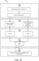
- FIG 10 is a schematic flow chart diagram illustrating one embodiment of a method 1000 for extracting EtherCAT datagrams from an EtherCAT frame.
- the method 1000 in the illustrated embodiments uses an SDAP 1002, a PDCP 1004, an RLC 1006, a MAC 1008, and a PHY 1010.
- the SDAP 1002 may identify an Ethertype from a QoS flow, and perform segmentation.
- the PDCP 1004 may perform header compression and perform datagram header compression.
- the RLC 1006 may transmit ARQ in response to receiving the compressed headers.
- the MAC 1008 may include a MUX that receives the compressed headers.
- the PHY 1010 may perform coding, resource mapping, and/or transmission.
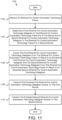
- Figure 11 is a schematic flow chart diagram illustrating another embodiment of a method 1100 for extracting EtherCAT datagrams from an EtherCAT frame.
- the method 1100 is performed by an apparatus, such as the network unit 104.
- the method 1100 may be performed by a processor executing program code, for example, a microcontroller, a microprocessor, a CPU, a GPU, an auxiliary processing unit, a FPGA, or the like.
- the method 1100 may include receiving 1102 an Ethernet for control automation technology frame.
- the method 1100 includes determining 1104 a first Ethernet for control automation technology datagram in the Ethernet for control automation technology frame for a first device (e.g., a first remote unit 102) and a second Ethernet for control automation technology datagram in the Ethernet for control automation technology frame for a second device (e.g., a second remote unit 102).
- the method 1100 includes extracting 1106 the first Ethernet for control automation technology datagram from the Ethernet for control automation technology frame to result in an extracted first Ethernet for control automation technology datagram and the second Ethernet for control automation technology datagram from the Ethernet for control automation technology frame to result in an extracted second Ethernet for control automation technology datagram.
- the method 1100 includes transmitting 1108 the extracted first Ethernet for control automation technology datagram directly to the first device.
- the method 1100 includes transmitting 1110 the extracted second Ethernet for control automation technology datagram directly to the second device.
- the method 1100 further comprises transmitting common header information corresponding to the Ethernet for control automation technology frame to the first device and the second device.
- the common header information is scheduled for multicast transmission and hence mapped to a multicast logical data channel and/or a multicast radio bearer.
- the extracted first Ethernet for control automation technology datagram and the extracted second Ethernet for control automation technology datagram are scheduled for unicast transmission and hence mapped to a unicast logical data channel and/or a unicast radio bearer.
- the method 1100 further comprises receiving an identifier that indicates an incoming packet as the Ethernet for control automation technology frame. In certain embodiments, the method further comprises parsing the Ethernet for control automation technology frame based on an identified frame profile. In some embodiments, extracting the first Ethernet for control automation technology datagram and the second Ethernet for control automation technology datagram comprises: segmenting the Ethernet for control automation technology frame into a plurality of service data application protocol protocol data units; and mapping each service data application protocol protocol data unit of the plurality of service data application protocol protocol data units to a corresponding radio bearer.
- each service data application protocol protocol data unit comprises a priority, a destination address, or a combination thereof.
- the method 1100 further comprises: receiving a first response from the first device, wherein the first response corresponds to the first Ethernet for control automation technology datagram; receiving a second response from the second device, wherein the first response corresponds to the first Ethernet for control automation technology datagram; and forming an Ethernet for control automation technology reply frame based on the first response and the second response.
- the method 1100 further comprises transmitting the Ethernet for control automation technology reply frame.
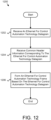
- Figure 12 is a schematic flow chart diagram illustrating one embodiment of a method 1200 for forming an EtherCAT frame from an EtherCAT datagram.
- the method 1200 is performed by an apparatus, such as the remote unit 102.
- the method 1200 may be performed by a processor executing program code, for example, a microcontroller, a microprocessor, a CPU, a GPU, an auxiliary processing unit, a FPGA, or the like.
- the method 1200 may include receiving 1202 an Ethernet for control automation technology datagram. In some embodiments, the method 1200 includes receiving 1204 common header information corresponding to the Ethernet for control automation technology datagram. In certain embodiments, the method 1200 includes forming 1206 an Ethernet for control automation technology frame based on the Ethernet for control automation technology datagram.
- the method 1200 further comprises transmitting the Ethernet for control automation technology frame to a device.
- the common header information is received from a multicast transmission.
- the Ethernet for control automation technology datagram and is received from a unicast transmission.
- the method 1200 further comprises receiving an identifier that indicates an incoming packet as the Ethernet for control automation technology datagram. In certain embodiments, the method 1200 further comprises: receiving an Ethernet for control automation technology response frame from the device, wherein the Ethernet for control automation technology response frame corresponds to the Ethernet for control automation technology frame; and forming a response to the Ethernet for control automation technology datagram based on extracting information from the Ethernet for control automation technology response frame. In some embodiments, the method 1200 further comprises transmitting the response to the Ethernet for control automation technology datagram.
- the method further comprises transmitting common header information corresponding to the Ethernet for control automation technology frame to the first device and the second device.
- the common header information is scheduled for multicast transmission.
- the extracted first Ethernet for control automation technology datagram and the extracted second Ethernet for control automation technology datagram are scheduled for unicast transmission.
- the method further comprises receiving an identifier that indicates an incoming packet as the Ethernet for control automation technology frame.
- the method further comprises parsing the Ethernet for control automation technology frame based on an identified frame profile.
- extracting the first Ethernet for control automation technology datagram and the second Ethernet for control automation technology datagram comprises: segmenting the Ethernet for control automation technology frame into a plurality of service data application protocol protocol data units; and mapping each service data application protocol protocol data unit of the plurality of service data application protocol protocol data units to a corresponding radio bearer.
- the method further comprises transmitting the Ethernet for control automation technology reply frame.
- an apparatus comprises: a receiver that receives an Ethernet for control automation technology frame; a processor that: determines a first Ethernet for control automation technology datagram in the Ethernet for control automation technology frame for a first device and a second Ethernet for control automation technology datagram in the Ethernet for control automation technology frame for a second device; and extracts the first Ethernet for control automation technology datagram from the Ethernet for control automation technology frame to result in an extracted first Ethernet for control automation technology datagram and the second Ethernet for control automation technology datagram from the Ethernet for control automation technology frame to result in an extracted second Ethernet for control automation technology datagram; and a transmitter that: transmits the extracted first Ethernet for control automation technology datagram directly to the first device; and transmits the extracted second Ethernet for control automation technology datagram directly to the second device.
- the transmitter transmits common header information corresponding to the Ethernet for control automation technology frame to the first device and the second device.
- the processor parses the Ethernet for control automation technology frame based on an identified frame profile.
- the processor extracting the first Ethernet for control automation technology datagram and the second Ethernet for control automation technology datagram comprises the processor: segmenting the Ethernet for control automation technology frame into a plurality of service data application protocol protocol data units; and mapping each service data application protocol protocol data unit of the plurality of service data application protocol protocol data units to a corresponding radio bearer.
- each service data application protocol protocol data unit comprises a priority, a destination address, or a combination thereof.
- the transmitter transmits the Ethernet for control automation technology reply frame.
- a method comprises: receiving an Ethernet for control automation technology datagram; receiving common header information corresponding to the Ethernet for control automation technology datagram; and forming an Ethernet for control automation technology frame based on the Ethernet for control automation technology datagram.
- the method further comprises transmitting the Ethernet for control automation technology frame to a device.
- the common header information is received from a multicast transmission.
- the Ethernet for control automation technology datagram and is received from a unicast transmission.
- the method further comprises receiving an identifier that indicates an incoming packet as the Ethernet for control automation technology datagram.
- the method further comprises transmitting the response to the Ethernet for control automation technology datagram.
- an apparatus comprises: a receiver that: receives an Ethernet for control automation technology datagram; and receives common header information corresponding to the Ethernet for control automation technology datagram; and a processor that forms an Ethernet for control automation technology frame based on the Ethernet for control automation technology datagram.
- the apparatus further comprises a transmitter that transmits the Ethernet for control automation technology frame to a device.
- the common header information is received from a multicast transmission.
- the receiver receives an Ethernet for control automation technology response frame from the device, wherein the Ethernet for control automation technology response frame corresponds to the Ethernet for control automation technology frame; and the processor forms a response to the Ethernet for control automation technology datagram based on extracting information from the Ethernet for control automation technology response frame.
- the apparatus further comprises a transmitter that transmits the response to the Ethernet for control automation technology datagram.
Landscapes
- Engineering & Computer Science (AREA)
- Computer Networks & Wireless Communication (AREA)
- Signal Processing (AREA)
- Computer Security & Cryptography (AREA)
- Mobile Radio Communication Systems (AREA)
- Information Transfer Between Computers (AREA)
Priority Applications (1)
| Application Number | Priority Date | Filing Date | Title |
|---|---|---|---|
| EP25151135.8A EP4518569A3 (de) | 2019-03-26 | 2019-03-26 | Extraktion von ethercat-datagrammen aus einem ethercat-rahmen |
Applications Claiming Priority (3)
| Application Number | Priority Date | Filing Date | Title |
|---|---|---|---|
| EP25151135.8A EP4518569A3 (de) | 2019-03-26 | 2019-03-26 | Extraktion von ethercat-datagrammen aus einem ethercat-rahmen |
| EP19726130.8A EP3949284B1 (de) | 2019-03-26 | 2019-03-26 | Extraktion von ethercat-datagrammen aus einem ethercat-frame |
| PCT/IB2019/000307 WO2020194005A1 (en) | 2019-03-26 | 2019-03-26 | Extracting ethercat datagrams from an ethercat frame |
Related Parent Applications (2)
| Application Number | Title | Priority Date | Filing Date |
|---|---|---|---|
| EP19726130.8A Division-Into EP3949284B1 (de) | 2019-03-26 | 2019-03-26 | Extraktion von ethercat-datagrammen aus einem ethercat-frame |
| EP19726130.8A Division EP3949284B1 (de) | 2019-03-26 | 2019-03-26 | Extraktion von ethercat-datagrammen aus einem ethercat-frame |
Publications (2)
| Publication Number | Publication Date |
|---|---|
| EP4518569A2 true EP4518569A2 (de) | 2025-03-05 |
| EP4518569A3 EP4518569A3 (de) | 2025-04-30 |
Family
ID=66641172
Family Applications (2)
| Application Number | Title | Priority Date | Filing Date |
|---|---|---|---|
| EP19726130.8A Active EP3949284B1 (de) | 2019-03-26 | 2019-03-26 | Extraktion von ethercat-datagrammen aus einem ethercat-frame |
| EP25151135.8A Pending EP4518569A3 (de) | 2019-03-26 | 2019-03-26 | Extraktion von ethercat-datagrammen aus einem ethercat-rahmen |
Family Applications Before (1)
| Application Number | Title | Priority Date | Filing Date |
|---|---|---|---|
| EP19726130.8A Active EP3949284B1 (de) | 2019-03-26 | 2019-03-26 | Extraktion von ethercat-datagrammen aus einem ethercat-frame |
Country Status (3)
| Country | Link |
|---|---|
| EP (2) | EP3949284B1 (de) |
| CN (2) | CN113615129B (de) |
| WO (1) | WO2020194005A1 (de) |
Families Citing this family (3)
| Publication number | Priority date | Publication date | Assignee | Title |
|---|---|---|---|---|
| US20240205046A1 (en) * | 2021-04-09 | 2024-06-20 | Lenovo (Singapore) Pte. Ltd. | Method and apparatuses for reliable industrial internet of things transmissions |
| WO2022237950A1 (en) * | 2021-05-11 | 2022-11-17 | Lenovo International Coöperatief U.A. | Ethernet-based fieldbus packet exchange within a mobile wireless communication network |
| CN115442218B (zh) * | 2022-09-05 | 2024-04-09 | 成都夸克光电技术有限公司 | 一种基于FPGA的Ethercat环形双冗余链路切换方法及系统 |
Family Cites Families (15)
| Publication number | Priority date | Publication date | Assignee | Title |
|---|---|---|---|---|
| US6856620B1 (en) * | 2000-09-08 | 2005-02-15 | Fujitsu Network Communications, Inc. | Method and system for transporting packet-switched control traffic in an optical network |
| EP1249970A1 (de) * | 2001-04-10 | 2002-10-16 | Alcatel | Eine Methode die die Qualität eines bevorzugten Kommunikationsdienst wie Sprache vor regulären Daten garantiert |
| CN1228945C (zh) * | 2002-11-14 | 2005-11-23 | 北京润光泰力科技发展有限公司 | 利用多条e1线路传输以太网数据的方法及系统 |
| CN1279720C (zh) * | 2003-05-29 | 2006-10-11 | 华为技术有限公司 | 以太网承载点对点协议的方法和系统 |
| KR20110071995A (ko) * | 2009-12-22 | 2011-06-29 | 한국전자통신연구원 | 이더넷-모스트 게이트웨이 장치 |
| AU2011218172B2 (en) * | 2010-02-16 | 2014-09-25 | Irobot Corporation | Internal communication system for a mobile robot |
| US20130173868A1 (en) * | 2011-12-29 | 2013-07-04 | Texas Instruments Incorporated | Generation of Activation List for Memory Translation and Memory Access Protection in Industrial Ethernet Standard |
| WO2014006446A1 (en) * | 2012-07-02 | 2014-01-09 | Freescale Semiconductor, Inc. | Ethercat packet forwarding with distributed clocking |
| JP6337469B2 (ja) * | 2013-12-27 | 2018-06-06 | 株式会社Ihi | 通信システム及び通信方法 |
| EP3119041B1 (de) * | 2014-04-28 | 2019-11-13 | Omron Corporation | Konstruktionsassistenzvorrichtung, konstruktionsassistenzverfahren und programm |
| US20180007712A1 (en) * | 2015-01-09 | 2018-01-04 | Interdigital Patent Holdings, Inc. | Methods, apparatuses and systems for supporting multi-user transmissions in a wireless local area network (wlan) system |
| CN104702474B (zh) * | 2015-03-11 | 2018-02-23 | 华中科技大学 | 一种基于FPGA的EtherCAT主站装置 |
| CN106341738B (zh) * | 2015-07-08 | 2021-02-02 | 杭州海康威视数字技术股份有限公司 | 流媒体网络传输的带宽计算方法、服务器端和系统 |
| DE102016125128B3 (de) * | 2016-12-21 | 2018-03-29 | Beckhoff Automation Gmbh | Datenübertragungsverfahren, Kommunikationsnetzwerk und Master-Teilnehmer |
| CN106656714A (zh) * | 2017-02-10 | 2017-05-10 | 广东工业大学 | 一种基于EtherCAT总线的通信协议方法及系统 |
-
2019
- 2019-03-26 EP EP19726130.8A patent/EP3949284B1/de active Active
- 2019-03-26 WO PCT/IB2019/000307 patent/WO2020194005A1/en not_active Ceased
- 2019-03-26 EP EP25151135.8A patent/EP4518569A3/de active Pending
- 2019-03-26 CN CN201980094267.2A patent/CN113615129B/zh active Active
- 2019-03-26 CN CN202411330344.9A patent/CN119341859A/zh active Pending
Also Published As
| Publication number | Publication date |
|---|---|
| EP3949284C0 (de) | 2025-02-26 |
| EP3949284B1 (de) | 2025-02-26 |
| CN113615129B (zh) | 2024-10-15 |
| CN119341859A (zh) | 2025-01-21 |
| EP4518569A3 (de) | 2025-04-30 |
| WO2020194005A1 (en) | 2020-10-01 |
| EP3949284A1 (de) | 2022-02-09 |
| CN113615129A (zh) | 2021-11-05 |
Similar Documents
| Publication | Publication Date | Title |
|---|---|---|
| US11877176B2 (en) | Determining data available for transmission | |
| US10904942B2 (en) | Network slice selection in a mobile communication network | |
| US12353183B2 (en) | Extracting EtherCAT datagrams from an EtherCAT frame | |
| CN116158099A (zh) | 基于用户装备能力的网络接入请求 | |
| EP3949284B1 (de) | Extraktion von ethercat-datagrammen aus einem ethercat-frame | |
| WO2022029742A1 (en) | Paging extensions | |
| CN113273293B (zh) | 确定用于多种模式的上行链路许可 | |
| WO2022141424A1 (en) | Relaying information using one or more relays | |
| US11876868B2 (en) | Deriving an operating system identity | |
| EP3744123B1 (de) | Priorisierte nutzung von logischen kanälen entsprechend logischen identifikatoren |
Legal Events
| Date | Code | Title | Description |
|---|---|---|---|
| PUAI | Public reference made under article 153(3) epc to a published international application that has entered the european phase |
Free format text: ORIGINAL CODE: 0009012 |
|
| STAA | Information on the status of an ep patent application or granted ep patent |
Free format text: STATUS: THE APPLICATION HAS BEEN PUBLISHED |
|
| AC | Divisional application: reference to earlier application |
Ref document number: 3949284 Country of ref document: EP Kind code of ref document: P |
|
| AK | Designated contracting states |
Kind code of ref document: A2 Designated state(s): AL AT BE BG CH CY CZ DE DK EE ES FI FR GB GR HR HU IE IS IT LI LT LU LV MC MK MT NL NO PL PT RO RS SE SI SK SM TR |
|
| REG | Reference to a national code |
Ref country code: DE Ref legal event code: R079 Free format text: PREVIOUS MAIN CLASS: H04W0080020000 Ipc: H04L0069220000 |
|
| PUAL | Search report despatched |
Free format text: ORIGINAL CODE: 0009013 |
|
| AK | Designated contracting states |
Kind code of ref document: A3 Designated state(s): AL AT BE BG CH CY CZ DE DK EE ES FI FR GB GR HR HU IE IS IT LI LT LU LV MC MK MT NL NO PL PT RO RS SE SI SK SM TR |
|
| RIC1 | Information provided on ipc code assigned before grant |
Ipc: H04L 12/40 20060101ALN20250327BHEP Ipc: G05B 19/042 20060101ALI20250327BHEP Ipc: H04L 12/18 20060101ALI20250327BHEP Ipc: H04W 80/02 20090101ALI20250327BHEP Ipc: H04L 69/22 20220101AFI20250327BHEP |
|
| STAA | Information on the status of an ep patent application or granted ep patent |
Free format text: STATUS: REQUEST FOR EXAMINATION WAS MADE |
|
| 17P | Request for examination filed |
Effective date: 20251022 |
|
| REG | Reference to a national code |
Ref country code: DE Ref legal event code: R079 Free format text: PREVIOUS MAIN CLASS: H04L0069220000 Ipc: H04L0012180000 |
|
| GRAP | Despatch of communication of intention to grant a patent |
Free format text: ORIGINAL CODE: EPIDOSNIGR1 |
|
| STAA | Information on the status of an ep patent application or granted ep patent |
Free format text: STATUS: GRANT OF PATENT IS INTENDED |
|
| RIC1 | Information provided on ipc code assigned before grant |
Ipc: H04L 12/18 20060101AFI20260304BHEP Ipc: H04L 69/22 20220101ALI20260304BHEP Ipc: H04W 80/02 20090101ALI20260304BHEP Ipc: G05B 19/042 20060101ALI20260304BHEP Ipc: H04L 12/40 20060101ALN20260304BHEP Ipc: H04W 4/70 20180101ALN20260304BHEP |
|
| INTG | Intention to grant announced |
Effective date: 20260313 |