EP4518209A2 - Kommunikationsverfahren und -vorrichtung - Google Patents
Kommunikationsverfahren und -vorrichtung Download PDFInfo
- Publication number
- EP4518209A2 EP4518209A2 EP23806784.7A EP23806784A EP4518209A2 EP 4518209 A2 EP4518209 A2 EP 4518209A2 EP 23806784 A EP23806784 A EP 23806784A EP 4518209 A2 EP4518209 A2 EP 4518209A2
- Authority
- EP
- European Patent Office
- Prior art keywords
- compressed data
- buffer
- group
- moment
- information
- Prior art date
- Legal status (The legal status is an assumption and is not a legal conclusion. Google has not performed a legal analysis and makes no representation as to the accuracy of the status listed.)
- Pending
Links
Images




Classifications
-
- H—ELECTRICITY
- H04—ELECTRIC COMMUNICATION TECHNIQUE
- H04W—WIRELESS COMMUNICATION NETWORKS
- H04W28/00—Network traffic management; Network resource management
- H04W28/02—Traffic management, e.g. flow control or congestion control
- H04W28/06—Optimizing the usage of the radio link, e.g. header compression, information sizing, discarding information
-
- H—ELECTRICITY
- H04—ELECTRIC COMMUNICATION TECHNIQUE
- H04L—TRANSMISSION OF DIGITAL INFORMATION, e.g. TELEGRAPHIC COMMUNICATION
- H04L1/00—Arrangements for detecting or preventing errors in the information received
- H04L1/12—Arrangements for detecting or preventing errors in the information received by using return channel
- H04L1/16—Arrangements for detecting or preventing errors in the information received by using return channel in which the return channel carries supervisory signals, e.g. repetition request signals
- H04L1/18—Automatic repetition systems, e.g. Van Duuren systems
- H04L1/1822—Automatic repetition systems, e.g. Van Duuren systems involving configuration of automatic repeat request [ARQ] with parallel processes
-
- H—ELECTRICITY
- H04—ELECTRIC COMMUNICATION TECHNIQUE
- H04L—TRANSMISSION OF DIGITAL INFORMATION, e.g. TELEGRAPHIC COMMUNICATION
- H04L1/00—Arrangements for detecting or preventing errors in the information received
- H04L1/12—Arrangements for detecting or preventing errors in the information received by using return channel
- H04L1/16—Arrangements for detecting or preventing errors in the information received by using return channel in which the return channel carries supervisory signals, e.g. repetition request signals
- H04L1/18—Automatic repetition systems, e.g. Van Duuren systems
- H04L1/1829—Arrangements specially adapted for the receiver end
- H04L1/1835—Buffer management
-
- H—ELECTRICITY
- H04—ELECTRIC COMMUNICATION TECHNIQUE
- H04L—TRANSMISSION OF DIGITAL INFORMATION, e.g. TELEGRAPHIC COMMUNICATION
- H04L1/00—Arrangements for detecting or preventing errors in the information received
- H04L1/12—Arrangements for detecting or preventing errors in the information received by using return channel
- H04L1/16—Arrangements for detecting or preventing errors in the information received by using return channel in which the return channel carries supervisory signals, e.g. repetition request signals
- H04L1/18—Automatic repetition systems, e.g. Van Duuren systems
- H04L1/1867—Arrangements specially adapted for the transmitter end
- H04L1/1874—Buffer management
-
- H—ELECTRICITY
- H04—ELECTRIC COMMUNICATION TECHNIQUE
- H04L—TRANSMISSION OF DIGITAL INFORMATION, e.g. TELEGRAPHIC COMMUNICATION
- H04L69/00—Network arrangements, protocols or services independent of the application payload and not provided for in the other groups of this subclass
- H04L69/04—Protocols for data compression, e.g. ROHC
-
- H—ELECTRICITY
- H04—ELECTRIC COMMUNICATION TECHNIQUE
- H04W—WIRELESS COMMUNICATION NETWORKS
- H04W28/00—Network traffic management; Network resource management
- H04W28/02—Traffic management, e.g. flow control or congestion control
- H04W28/10—Flow control between communication endpoints
- H04W28/14—Flow control between communication endpoints using intermediate storage
Definitions
- This application relates to the field of communication technologies, and in particular, to a communication method and apparatus.
- uplink data compression uplink data compression
- the existing UDC technology is usually used at a packet data convergence protocol (packet data convergence protocol, PDCP) layer.
- An application mechanism of the UDC technology is as follows: A transmitting end sends UDC data to a receiving end, where the UDC data is carried in PDCP packets.
- the receiving end may determine, based on sequence numbers (sequence numbers, SNs) included in headers of the received PDCP packets, PDCP packets that fail to be received, and the receiving end may send a PDCP control (control) protocol data unit (protocol data unit, PDU) to the transmitting end, to indicate the PDCP packets that fail to be received.
- PDU protocol data unit
- the transmitting end may retransmit the PDCP packets that fail to be received.
- This mechanism is equivalent to adding a retransmission mechanism to the PDCP layer.
- a retransmission mechanism is also present at another protocol layer. After the PDCP retransmission mechanism is added, there are two layers of retransmission mechanisms. This may result in a plurality of retransmissions of same UDC data, wasting transmission resources.
- Embodiments of this application provide a communication method and apparatus, to reduce transmission resources.
- a communication method may be performed by a sending device, or may be performed by another device including a function of the sending device, or may be performed by a chip system or another functional module.
- the chip system or the functional module can implement the function of the sending device.
- the chip system or the functional module is, for example, disposed in the sending device.
- the sending device is, for example, a terminal device in air interface communication, a terminal device in sidelink communication, or a STA in Wi-Fi communication.
- the method includes: compressing first original data by using a first buffer, to obtain first compressed data, where the first buffer is a buffer corresponding to UDC; sending the first compressed data to a receiving device at a first moment; receiving first feedback information from the receiving device at a second moment, where the first feedback information indicates that the first compressed data is successfully received, and the first feedback information is physical layer feedback information or MAC layer feedback information; and updating the first buffer at a third moment based on the first original data in response to the first feedback information, to obtain a second buffer, where the second buffer includes the first original data.
- the second moment is later than the first moment
- the third moment is later than the second moment.
- whether data corresponding to an uplink compression technology is successfully received or fails to be received can be fed back, by using a feedback mechanism corresponding to the first feedback information, without introducing a feedback mechanism of another protocol layer (for example, a PDCP layer), reducing feedback resource overheads when ensuring transmission reliability.
- a feedback mechanism corresponding to the first feedback information without introducing a feedback mechanism of another protocol layer (for example, a PDCP layer), reducing feedback resource overheads when ensuring transmission reliability.
- the method further includes: sending first information at a fourth moment, where the first information includes first indication information, the first indication information indicates the receiving device to update a third buffer to obtain a fourth buffer, data included in the third buffer is the same as data included in the first buffer, data included in the fourth buffer is the same as data included in the second buffer, and the fourth moment is later than the second moment.
- the receiving device also maintains a buffer corresponding to the UDC, for example, the third buffer.
- the sending device may indicate, by using the first indication information, the receiving device to update the third buffer, so that an occasion for updating a buffer by the receiving device is consistent with an occasion for updating a buffer by the sending device, maintaining consistency between the buffers of the two ends.
- the method further includes: receiving second feedback information at a fifth moment, where the second feedback information indicates whether the first information is successfully received, and the fifth moment is later than the fourth moment.
- the receiving device may send the second feedback information to the sending device, so that the sending device can determine whether the first information is successfully received or fails to be received.
- the second feedback information when the second feedback information is a first value, the second feedback information indicates that the first information is successfully received; or when the second feedback information is a second value, the second feedback information indicates that the first information fails to be received.
- the first value is "1", and the second value is "0"; or the first value is "ACK”, and the second value is "NACK”; or the first value is "true", and the second value is "false”.
- the updating the first buffer at a third moment based on the first original data, to obtain a second buffer includes: when the second feedback information is the first value, updating the first buffer at the third moment based on the first original data, to obtain the second buffer, where the third moment is later than the fifth moment. If the second feedback information is the first value, the sending device may determine that the receiving device has successfully received the first information. In this case, the sending device may infer that the receiving device can determine that the third buffer needs to be updated. In this case, when the sending device updates the first buffer again, it is equivalent to that the sending device downloads and updates the first buffer in a case that the sending device determines that the receiving device can update the third buffer. This helps maintain consistency between the buffers of the two ends.
- the first information further includes second indication information, the second indication information indicates second compressed data, and the second compressed data is generated based on the second buffer.
- the first information may further indicate the second compressed data.
- the first information includes the second compressed data, and the second compressed data is, for example, a next piece of compressed data of the first compressed data.
- the sending device may indicate, by using information about sending the next piece of compressed data, the receiving device to update the third buffer, and does not need to send additional information to indicate the receiving device to update the third buffer. This helps reduce transmission overheads.
- the first information further includes second indication information
- the second indication information indicates second compressed data
- the second compressed data is generated based on the first buffer.
- the sending device may first update the first buffer to obtain the second buffer, and then perform compression based on the second buffer to obtain the second compressed data, so that the buffer can be updated in a timely manner.
- the sending device may not update the first buffer temporarily, but continue to perform compression by using the first buffer to obtain the second compressed data.
- the sending device may update the first buffer after receiving the second feedback information. In this manner, the sending device may update the first buffer after determining that the receiving device can update the third buffer. This helps maintain consistency of the buffers of the two ends.
- the method further includes: sending second information, where the second information indicates first duration, so that the third moment is equal to or later than a moment obtained by adding the first duration to the fourth moment, or the third moment is equal to or later than a moment obtained by adding the first duration to the fifth moment.
- a moment at which the receiving device sends feedback information is usually later than a moment at which compressed data is received. If the sending device updates the first buffer after receiving the second feedback information, and the receiving device may update the third buffer after receiving the first indication information, an occasion for updating the third buffer by the receiving device may be inconsistent with an occasion for updating the first buffer by the sending device. Therefore, the first duration may be set.
- the receiving device may wait the first duration before updating a formal buffer.
- the sending device may also wait the first duration before updating the formal buffer.
- the first duration is set, so that the sending device and the receiving device can keep consistency in occasions for updating the buffer.
- the first indication information indicates a sequence number of the first compressed data.
- the first indication information may indicate the sequence number of the first compressed data, and is equivalent to indicating the receiving device to update the third buffer based on the first compressed data. It can be learned that this indication manner is simple and clear.
- the first indication information is the sequence number of the first compressed data.
- a manner in which the first indication information indicates the sequence number of the first compressed data is, for example, that the first indication information includes the sequence number of the first compressed data.
- the first indication information may alternatively indicate the sequence number of the first compressed data in another manner. This is not limited in embodiments of this application.
- the first compressed data includes M pieces of compressed data arranged based on sequence numbers
- the first indication information is a sequence number of a last piece of compressed data in the M pieces of compressed data
- M is a positive integer.
- the first indication information includes the sequence number of the last piece of compressed data, so that the receiving device can determine that the compressed data corresponding to the sequence number included in the first indication information and compressed data corresponding to a sequence number before the sequence number are both used to update the third buffer.
- the first indication information may include only one sequence number. This helps reduce overheads of the first information.
- the first compressed data includes M pieces of compressed data arranged based on sequence numbers
- the first information includes at least one group of fields
- a group of fields in the at least one group of fields includes a start field and an end field
- the start field includes a sequence number of a 1 st piece of compressed data in a group of compressed data in the M pieces of compressed data
- the end field includes a sequence number of a last piece of compressed data in the group of compressed data
- the group of compressed data is compressed data with consecutive sequence numbers.
- sequence numbers of adjacent compressed data in the M pieces of compressed data may be inconsecutive. In this case, this implementation may be used.
- a plurality of groups of fields respectively include sequence numbers of different compressed data, where a group of fields includes a group of consecutive sequence numbers, and sequence numbers included in different groups of fields are inconsecutive.
- the first indication information can completely indicate the M pieces of compressed data.
- a group of fields includes only a sequence number of a 1 st piece of compressed data and a sequence number of a last piece of compressed data in a group of consecutive compressed data, and does not necessarily include sequence numbers of all pieces of compressed data. This helps reduce overheads of the first information.
- the first compressed data includes M pieces of compressed data arranged based on sequence numbers
- the first information includes at least one group of fields
- a group of fields in the at least one group of fields includes a start field and an offset field
- the start field includes a sequence number of a 1 st piece of compressed data in a group of compressed data in the M pieces of compressed data
- the offset field includes an offset between a sequence number of a last piece of compressed data in the group of compressed data and the sequence number of the 1 st piece of compressed data
- the group of compressed data is compressed data with consecutive sequence numbers.
- sequence numbers of adjacent compressed data in the M pieces of compressed data may be inconsecutive. In this case, this implementation may also be used.
- a group of fields may include a sequence number of a 1 st piece of compressed data in a group of compressed data, and an offset between a last piece of compressed data and the 1 st piece of compressed data.
- a data amount of the offset may be less than a data amount of a sequence number of the last piece of compressed data. Therefore, this manner can further reduce overheads of the first information.
- the first compressed data includes M pieces of compressed data arranged based on sequence numbers
- the first information includes a first group of fields and a second group of fields
- the first group of fields includes a start field and an end field
- the start field includes a sequence number of a 1 st piece of compressed data in a group of compressed data in the M pieces of compressed data
- the end field includes a sequence number of a last piece of compressed data in the group of compressed data
- the group of compressed data is compressed data with consecutive sequence numbers
- the second group of fields includes a sequence number field
- the sequence number field includes a sequence number of a piece of compressed data in the M pieces of compressed data
- M is an integer greater than or equal to 2.
- sequence numbers of adjacent compressed data in the M pieces of compressed data may be inconsecutive.
- this implementation may further be used.
- there are a plurality of groups of compressed data in the M pieces of compressed data where at least one group of compressed data may include only one piece of compressed data. If this piece of compressed data is also indicated by two fields, resource overheads are increased. Therefore, one piece of compressed data may be indicated by a sequence number field.
- a group of compressed data includes a plurality of pieces of compressed data, a format similar to the first group of fields may be used for indication. In this manner, the first indication information can indicate the M pieces of compressed data, and overheads are low.
- the first compressed data includes M pieces of compressed data
- the first information includes at least one group of fields
- a group of fields in the at least one group of fields includes sequence numbers of N pieces of compressed data
- the N pieces of compressed data are compressed data with consecutive sequence numbers
- remaining fields in the at least one group of fields include sequence numbers of N-M pieces of compressed data
- the M pieces of compressed data are compressed data remaining after the N-M pieces of compressed data are excluded from the N pieces of compressed data
- N is an integer greater than or equal to M.
- the sequence numbers of the N pieces of compressed data may be indicated by the group of fields, and the sequence numbers of the N-M pieces of compressed data are indicated by the remaining fields. This is equivalent to excluding the N-M pieces of compressed data from the N pieces of compressed data, so that the M pieces of compressed data are indicated. For example, if a value of N-M is small, this indication manner helps reduce overheads of the first information.
- the first information further includes second indication information, the second indication information indicates second compressed data.
- the first information may further indicate the second compressed data.
- the first information includes the second compressed data
- the second compressed data is, for example, a next piece of compressed data of the first compressed data.
- the sending device may indicate, by using information about sending the next piece of compressed data, the receiving device to update the third buffer, and does not need to send additional information to indicate the receiving device to update the third buffer. This helps reduce transmission overheads.
- the first indication information indicates an offset between a sequence number of the first compressed data and a sequence number of the second compressed data.
- the first indication information may further indicate the first compressed data in a manner of indicating the offset between the sequence number of the first compressed data and the sequence number of the second compressed data.
- a data amount of the offset may be less than a data amount of the sequence number of the first compressed data, and overheads of the first information can be reduced by indicating the offset.
- another communication method may be performed by a receiving device, or may be performed by another device including a function of the receiving device, or may be performed by a chip system or another functional module.
- the chip system or the functional module can implement the function of the receiving device.
- the chip system or the functional module is, for example, disposed in the receiving device.
- the receiving device is, for example, an access network device in air interface communication, a terminal device in sidelink communication, or an AP in Wi-Fi communication.
- the method includes: receiving first compressed data from a sending device at a first moment; sending first feedback information to the sending device at a second moment, where the first feedback information indicates that the first compressed data is successfully received, and the first feedback information is physical layer feedback information or MAC layer feedback information; and updating a third buffer at a sixth moment based on the first compressed data, to obtain a fourth buffer, where the fourth buffer includes first original data obtained by decompressing the first compressed data, and the third buffer is a buffer corresponding to an uplink compression technology UDC, where the second moment is later than the first moment, and the sixth moment is later than the second moment.
- the method further includes: receiving first information at a fourth moment, where the first information includes first indication information, the first indication information indicates the receiving device to update the third buffer to obtain the fourth buffer, and the fourth moment is later than the second moment.
- the method further includes: sending second feedback information at a fifth moment, where the second feedback information indicates whether the first information is successfully received, and the fifth moment is later than the fourth moment.
- the second feedback information when the second feedback information is a first value, the second feedback information indicates that the first information is successfully received; or when the second feedback information is a second value, the second feedback information indicates that the first information fails to be received.
- the updating a third buffer at a sixth moment based on the first compressed data, to obtain a fourth buffer includes: when the first information is successfully received, updating the third buffer at the sixth moment based on the first compressed data, to obtain the fourth buffer.
- the first information further includes second indication information, the second indication information indicates second compressed data, and the second compressed data is generated based on the second buffer.
- the first information further includes second indication information, the second indication information indicates second compressed data, and the second compressed data is generated based on the first buffer.
- the method further includes: receiving second information, where the second information indicates first duration, so that the sixth moment is equal to or later than a moment obtained by adding the first duration to the fourth moment, or the sixth moment is equal to or later than a moment obtained by adding the first duration to the fifth moment.
- the first indication information indicates a sequence number of the first compressed data.
- the first indication information is the sequence number of the first compressed data.
- the first compressed data includes M pieces of compressed data arranged based on sequence numbers
- the first indication information is a sequence number of a last piece of compressed data in the M pieces of compressed data
- M is a positive integer
- the first compressed data includes M pieces of compressed data arranged based on sequence numbers
- the first information includes at least one group of fields
- a group of fields in the at least one group of fields includes a start field and an end field
- the start field includes a sequence number of a 1 st piece of compressed data in a group of compressed data in the M pieces of compressed data
- the end field includes a sequence number of a last piece of compressed data in the group of compressed data
- the group of compressed data is compressed data with consecutive sequence numbers.
- the first compressed data includes M pieces of compressed data arranged based on sequence numbers
- the first information includes at least one group of fields
- a group of fields in the at least one group of fields includes a start field and an offset field
- the start field includes a sequence number of a 1 st piece of compressed data in a group of compressed data in the M pieces of compressed data
- the offset field includes an offset between a sequence number of a last piece of compressed data in the group of compressed data and the sequence number of the 1 st piece of compressed data
- the group of compressed data is compressed data with consecutive sequence numbers.
- the first compressed data includes M pieces of compressed data arranged based on sequence numbers
- the first information includes a first group of fields and a second group of fields
- the first group of fields includes a start field and an end field
- the start field includes a sequence number of a 1 st piece of compressed data in a group of compressed data in the M pieces of compressed data
- the end field includes a sequence number of a last piece of compressed data in the group of compressed data
- the group of compressed data is compressed data with consecutive sequence numbers
- the second group of fields includes a sequence number field
- the sequence number field includes a sequence number of a piece of compressed data in the M pieces of compressed data
- M is an integer greater than or equal to 2.
- the first compressed data includes M pieces of compressed data
- the first information includes at least one group of fields
- a group of fields in the at least one group of fields includes sequence numbers of N pieces of compressed data
- the N pieces of compressed data are compressed data with consecutive sequence numbers
- remaining fields in the at least one group of fields include sequence numbers of N-M pieces of compressed data
- the M pieces of compressed data are compressed data remaining after the N-M pieces of compressed data are excluded from the N pieces of compressed data
- N is an integer greater than or equal to M.
- the first information further includes the second indication information, the second indication information indicates the second compressed data, and the first indication information indicates an offset between a sequence number of the first compressed data and a sequence number of the second compressed data.
- a communication apparatus may be the sending device according to the first aspect, or a communication device including the sending device, or a functional module in the sending device, for example, a baseband apparatus or a chip system.
- the communication apparatus includes a baseband apparatus and a radio frequency apparatus.
- the communication apparatus includes a processing unit (or referred to as a processing module sometimes) and a transceiver unit (or referred to as a transceiver module sometimes).
- the transceiver unit can implement a sending function and a receiving function. When the transceiver unit implements the sending function, the transceiver unit may be referred to as a sending unit (or referred to as a sending module sometimes).
- the transceiver unit When the transceiver unit implements the receiving function, the transceiver unit may be referred to as a receiving unit (or referred to as a receiving module sometimes).
- the sending unit and the receiving unit may be a same functional module, the functional module is referred to as a transceiver unit, and the functional module can implement the sending function and the receiving function.
- the sending unit and the receiving unit may be different functional modules, and the transceiver unit is a general term for these functional modules.
- the processing unit is configured to compress first original data by using a first buffer, to obtain first compressed data, where the first buffer is a buffer corresponding to UDC.
- the transceiver unit (or the sending unit) is configured to send the first compressed data to a receiving device at a first moment.
- the transceiver unit (or the receiving unit) is configured to receive first feedback information from the receiving device at a second moment, where the first feedback information indicates that the first compressed data is successfully received, and the first feedback information is physical layer feedback information or MAC layer feedback information.
- the processing unit is further configured to: update the first buffer at a third moment based on the first original data in response to the first feedback information, to obtain a second buffer, where the second buffer includes the first original data.
- the second moment is later than the first moment
- the third moment is later than the second moment.
- the communication apparatus further includes a storage unit (or referred to as a storage module sometimes).
- the processing unit is configured to be coupled to the storage unit, and execute a program or instructions in the storage unit, so that the communication apparatus performs a function of the sending device according to the first aspect.
- the communication apparatus may be the receiving device according to the second aspect, or a communication device including the receiving device, or a functional module in the receiving device, for example, a baseband apparatus or a chip system.
- the communication apparatus includes a processing unit (or referred to as a processing module sometimes) and a transceiver unit (or referred to as a transceiver module sometimes).
- a processing unit or referred to as a processing module sometimes
- a transceiver unit or referred to as a transceiver module sometimes.
- the transceiver unit refer to the third aspect.
- the transceiver unit (or the receiving unit) is configured to receive first compressed data from a sending device at a first moment.
- the transceiver unit (or the sending unit) is configured to send first feedback information to the sending device at a second moment, where the first feedback information indicates that the first compressed data is successfully received, and the first feedback information is physical layer feedback information or MAC layer feedback information.
- the processing unit is configured to update a third buffer at a sixth moment based on the first compressed data, to obtain a fourth buffer, where the fourth buffer includes first original data obtained by decompressing the first compressed data, and the third buffer is a buffer corresponding to UDC.
- the second moment is later than the first moment
- the sixth moment is later than the second moment.
- the communication apparatus further includes a storage unit (or referred to as a storage module sometimes).
- the processing unit is configured to be coupled to the storage unit, and execute a program or instructions in the storage unit, so that the communication apparatus performs a function of the receiving device according to the second aspect.
- the communication apparatus may be a sending device, or a chip or a chip system in a sending device; or the communication apparatus may be a receiving device, or a chip or a chip system in a receiving device.
- the communication apparatus includes a communication interface and a processor, and optionally, further includes a memory.
- the memory is configured to store a computer program.
- the processor is coupled to the memory and the communication interface. When the processor reads the computer program or instructions, the communication apparatus is enabled to perform the method performed by the sending device or the receiving device in the foregoing aspects.
- a communication system including a sending device and a receiving device, where the sending device is configured to perform the communication method according to the first aspect, and the receiving device is configured to perform the communication method according to the second aspect.
- a computer-readable storage medium configured to store a computer program or instructions. When the computer program or the instructions are run, the method performed by the sending device or the receiving device in the foregoing aspects is implemented.
- a computer program product including instructions is provided.
- the methods according to the foregoing aspects are implemented.
- a chip system including a processor and an interface.
- the processor is configured to invoke instructions from the interface and run the instructions, to enable the chip system to implement the methods in the foregoing aspects.
- a quantity of nouns represents "a singular noun or plural nouns", that is, "one or more".
- At least one means one or more, and "a plurality of” means two or more.
- “And/Or” describes an association relationship between associated objects and indicates that three relationships may exist. For example, A and/or B may indicate the following three cases: Only A exists, both A and B exist, and only B exists, where A and B may be singular or plural.
- the character “/" generally indicates an "or” relationship between the associated objects. For example, A/B indicates A or B.
- At least one of the following items (pieces) refers to any combination of these items, including any combination of singular items (pieces) or plural items (pieces).
- at least one of a, b, or c indicates a, b, c, a and b, a and c, b and c, or a, b, and c, where a, b, and c may be singular or plural.
- ordinal numbers such as “first” and “second” described in embodiments of this application are used to distinguish between a plurality of objects, but are not used to limit sizes, content, sequences, time sequences, priorities, importance, or the like of the plurality of objects.
- a first radio resource control (radio resource control, RRC) request message and a second RRC request message may be a same message, or may be different messages.
- the names do not indicate that the two messages are different in content, size, application scenario, transmitting end/receiving end, priority, importance, or the like.
- step numbers in embodiments described in this application are merely used to distinguish between different steps, but are not used to limit a sequence of the steps. For example, S301 may be performed before S302, may be performed after S302, or may be performed at the same time with S302.
- a terminal device is a device having a wireless transceiver function, and may be a fixed device, a mobile device, a handheld device (for example, a mobile phone), a wearable device, a vehicle-mounted device, or a wireless apparatus (for example, a communication module, a modem, or a chip system) built in the device.
- the terminal device is configured to connect people, things, machines, and the like, and may be widely used in various scenarios.
- the terminal device includes but is not limited to terminal devices in scenarios such as cellular communication, device-to-device (device-to-device, D2D) communication, vehicle-to-everything (vehicle-to-everything, V2X), machine-to-machine/machine-type communications (machine-to-machine/machine-type communications, M2M/MTC), internet of things (internet of things, IoT), virtual reality (virtual reality, VR), augmented reality (augmented reality, AR), industrial control (industrial control), self-driving (self-driving), remote medical (remote medical), a smart grid (smart grid), smart furniture, smart office, smart wearables, smart transportation, a smart city (smart city), an uncrewed aerial vehicle, and a robot.
- terminal devices in scenarios such as cellular communication, device-to-device (device-to-device, D2D) communication, vehicle-to-everything (vehicle-to-everything,
- the terminal device may be sometimes referred to as a UE, a terminal, an access station, a UE station, a remote station, a wireless communication device, a user apparatus, or the like.
- a UE a terminal
- an access station a UE station
- a remote station a wireless communication device
- a user apparatus a user apparatus
- a network device in embodiments of this application includes, for example, an access network device and/or a core network device.
- the access network device is a device having a wireless transceiver function, and is configured to communicate with the terminal device.
- the access network device includes but is not limited to a base station (a base transceiver station (base transceiver station, BTS), a NodeB, an eNodeB/eNB, or a gNodeB/gNB), a transmission reception point (transmission reception point, TRP), a subsequent evolved base station in the 3rd generation partnership project (3rd generation partnership project, 3GPP), an access node in a wireless fidelity (wireless fidelity, Wi-Fi) system, a wireless relay node, a wireless backhaul node, or the like.
- a base station a base transceiver station (base transceiver station, BTS), a NodeB, an eNodeB/eNB, or a gNodeB/gNB
- the base station may be a macro base station, a micro base station, a picocell base station, a small cell, a relay station, or the like.
- a plurality of base stations may support networks using a same access technology, or may support networks using different access technologies.
- the base station may include one or more co-site or non-co-site transmission reception points.
- the access network device may be a radio controller in a cloud radio access network (cloud radio access network, CRAN) scenario, a central unit (central unit, CU), and/or a distributed unit (distributed unit, DU).
- the access network device may be a server or the like.
- a network device in a vehicle-to-everything (vehicle-to-everything, V2X) technology may be a roadside unit (roadside unit, RSU).
- the following uses an example in which the access network device is a base station for description.
- the base station may communicate with the terminal device, or may communicate with the terminal device via a relay station.
- the terminal device may communicate with a plurality of base stations in different access technologies.
- the core network device is configured to implement functions such as mobility management, data processing, session management, and policy and charging. Names of devices that implement core network functions in systems of different access technologies may be different. This is not limited in embodiments this application.
- a 5G system is used as an example.
- the core network device includes an access and mobility management function (access and mobility management function, AMF), a session management function (session management function, SMF), a policy control function (policy control function, PCF), a user plane function (user plane function, UPF), or the like.
- AMF access and mobility management function
- SMF session management function
- PCF policy control function
- UPF user plane function
- a communication apparatus configured to implement a function of the network device may be a network device, or may be an apparatus that can support the network device in implementing the function, for example, a chip system.
- the apparatus may be installed in the network device.
- an example in which the apparatus configured to implement the function of the network device is a network device is used to describe the technical solutions provided in embodiments of this application.
- UDC allows new data to be compressed based on previously compressed data, reducing a requirement for a data transmission rate.
- data of a service is strongly similar. Therefore, new data may be compressed with reference to compressed data, to reduce a capacity of a data packet.
- uplink data is mainly transmission control protocol (transmission control protocol, TCP) feedback data or textual description data, and a large quantity of repeated characters easily appear between the data.
- TCP transmission control protocol
- ACK acknowledgeledgment
- NACK negative acknowledgment
- IP internet protocol
- UDC may be used to reduce sending of repeated characters in a manner in which current data is compressed and encoded based on previous data, reducing a capacity of a data packet. Further, for a service such as web page browsing, it may be considered that text content carried in different data is also highly repeated, and UDC may also be used to reduce repeatedly transmitted text data, reducing a capacity of a data packet.
- a transmitting end maintains a compression buffer (buffer) that may also be referred to as a dictionary (dictionary), in other words, the compression buffer includes the dictionary.
- the transmitting end may search the compression buffer for a character that is the same as a character included in the original data, and compress the original data based on the character found in the compression buffer, to obtain compressed data. After the compressed data is obtained, the original data corresponding to the compressed data is written into the compression buffer.
- a size of the compression buffer is fixed, for example, 8K bytes or 32K bytes.
- the compression buffer is full, newly written data causes old data in the compression buffer to overflow. For example, data earliest stored in the compression buffer is cleared, to write new data.
- a receiving end also maintains a compression buffer. After receiving compressed data, the receiving end decompresses the compressed data based on the compression buffer. Therefore, to enable reliable transmission of UDC data, statuses of the compression buffer at the receiving end and the compression buffer at the transmitting end need to be consistent, in other words, content of the two compression buffers needs to be consistent.
- FIG. 1A shows a PDCP header (header) and a UDC header.
- a length of a PDCP SN is 12 bits (bits) is used.
- first two bytes are the PDCP header, a 3 rd byte is the UDC header, and a 4 th byte may include UDC data.
- An "FU" field indicates whether data corresponding to the UDC header is compressed by using UDC
- an "FR” field indicates whether to reset a UDC compression buffer
- a "checksum” field is used by a receiving end to check whether the UDC compression buffer is synchronized.
- UDC compression buffers of a transmitting end and the receiving end are not synchronized, and the receiving end may send a control PDU to the transmitting end.
- a UDC header of the control PDU refer to FIG. 1B , where an "FE" field indicates the check on the "checksum”. For example, when a value of the "FE" field is "1", it indicates that the check on the "checksum” fails.
- the transmitting end may reset the UDC compression buffer of the transmitting end, and after the reset, send a data packet (a header is shown in FIG.
- the receiving end may reset the UDC compression buffer, and process the data packet based on the reset UDC compression buffer.
- a transmitting end sends five PDCP packets to a receiving end: a PDCP packet 1 to a PDCP packet 5, where one PDCP packet carries one piece of UDC data, and the UDC data carried in the PDCP packet is compressed data. If the receiving end successfully receives the PDCP packet 1 and the PDCP packet 2, the receiving end may update a compression buffer of the receiving end based on UDC data included in the PDCP packet 1 and the PDCP packet 2. However, after receiving the PDCP packet 4, the receiving end finds that the PDCP packet 3 is not received. In this case, the receiving end cannot decompress the PDCP packet 4.
- the receiving end may send a PDCP control PDU to the transmitting end, to indicate that the PDCP packet 3 fails to be received.
- the transmitting end retransmits the PDCP packet 3.
- the receiving end may update the compression buffer of the receiving end based on UDC data carried in the PDCP packet 3, to decompress the PDCP packet 4 and a subsequent PDCP packet by using the updated compression buffer.
- a retransmission mechanism is also present at another protocol layer.
- a retransmission mechanism at a physical layer exists in communication between UEs or communication between a UE and an access network device.
- a feedback mechanism at a media access control (media access control, MAC) layer exists in communication between a station (station, STA) and an access point (access point, AP) in a wireless fidelity (wireless fidelity, Wi-Fi) system.
- MAC media access control
- first feedback information is physical layer feedback information or MAC layer feedback information.
- first feedback information may be physical layer feedback information.
- the sending device is a STA and the receiving device is an AP
- the first feedback information may be MAC layer feedback information.
- 4th generation mobile communication technology 4th generation, 4G
- 4G 4th generation mobile communication technology
- LTE long term evolution
- 5G for example, an NR system
- next generation mobile communication system for example, a next generation mobile communication system or another similar communication system
- short-distance communication system for example, a Wi-Fi system or another short-distance communication system.
- the technical solutions provided in embodiments of this application may be applied to a device-to-device (device-to-device, D2D) scenario, for example, an NR-D2D scenario, or may be applied to a V2X scenario, for example, an NR-V2X scenario.
- D2D device-to-device
- V2X virtual-to-device
- the technical solutions may be applied to internet of vehicles, for example, V2X, or may be applied to a field such as intelligent driving, assisted driving, or intelligent connected vehicles. If the technical solutions are applied to a D2D scenario, both communication parties may be UEs.
- a communication sender may be a UE, and a communication receiver may be a network device (for example, an access network device), or both communication parties may be network devices.
- a communication sender may be a STA, and a communication receiver may be an AP.
- FIG. 2 is a diagram of an application scenario according to an embodiment of this application.
- FIG. 2 includes a sending device and a receiving device.
- both the sending device and the receiving device are UEs; or the sending device is a UE, and the receiving device is an access network device; or the sending device is a STA, and the receiving device is an AP.
- Data described in embodiments of this application is data corresponding to an uplink data compression technology, and the data may include original data and compressed data.
- the "original data” refers to data before compression is performed by using the uplink data compression technology, or refers to data obtained by performing decompression by using the uplink data compression technology; and the “compressed data” refers to data obtained by compressing the "original data” by using the uplink data compression technology.
- the uplink data compression technology is, for example, a UDC technology, or another technology in which current data is compressed and encoded based on previous data. In the following description process, an example in which the uplink data compression technology is the UDC technology is used.
- SN and PDCP SN may be a same concept, and may be replaced with each other.
- FIG. 3 is a flowchart of the method.
- the method may be applied to the network architecture shown in FIG. 2 .
- a sending device in the method is the sending device in FIG. 2
- a receiving device in the method is the receiving device in FIG. 2 .
- the sending device compresses first original data by using a first buffer, to obtain first compressed data.
- the first buffer is, for example, a buffer corresponding to a UDC technology, and may also be referred to as a UDC buffer.
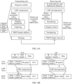
- FIG. 4A shows a data sending and receiving procedure.
- the sending device may communicate with the receiving device by using a sidelink (sidelink, SL).
- a radio link control (radio link control, RLC) layer may be in unacknowledged mode (unacknowledged mode, UM) or (transparent mode, TM).
- the sending device is a UE, and the receiving device is an access network device.
- the first original data is, for example, to-be-sent data, and the first original data may include one or more pieces of to-be-sent data. If the first original data includes a plurality of pieces of data, the plurality of pieces of data may be separately processed.
- FIG. 4A shows a process of processing one piece of data included in the first original data.
- the sending device adds a sequence number (for example, a step shown by "sequence number" in FIG. 4A ) to the first original data, and compresses (compression), at a PDCP layer based on the UDC technology, the first original data to which the sequence number is added.
- the sending device may compress, by using the first buffer, the first original data to which the sequence number is added, to obtain compressed data.
- the first compressed data in this embodiment of this application is the compressed data.
- a UDC header may be added to the compressed data at the PDCP layer. For the UDC header, refer to FIG. 1A .
- the first original data is associated with a PDCP service data unit (service data unit, SDU). Therefore, the PDCP layer assembles the data to which the UDC header is added, performs operations such as integrity protection (integrity protection) and ciphering (ciphering) on the data, adds a PDCP header (add PDCP header) to a result obtained through the operations, obtains a PDCP protocol data unit (protocol data unit, PDU) based on the result to which the PDCP header is added, and finally sends the PDCP PDU to the corresponding RLC layer (represented as routing (routing) in FIG. 4A ).
- the RLC layer considers the received information as an RLC SDU.
- the RLC layer performs an operation such as segmentation on the RLC SDU, and adds an RLC header to the RLC SDU to obtain an RLC PDU.
- the RLC layer sends the RLC PDU to a media access control (media access control, MAC) layer of the sending device.
- the MAC layer adds a MAC header to the received data, and multiplexes, into a MAC PDU (MPDU), the data to which the MAC header is added. For example, in a multiplexing manner, the MAC layer may add, to the MPDU, the data to which the MAC header is added, and the MPDU may include the data to which the MAC header is added.
- MPDU MAC PDU
- Main functions of the MAC layer are to multiplex (for example, add) a plurality of pieces of data from an upper layer (for example, the RLC layer) into an MPDU, and transfer the MPDU to a physical (PHY) layer.
- the physical layer performs processing such as cyclic redundancy check (cyclic redundancy check, CRC), channel encoding, interleaving, rate matching, and mapping on the MPDU, and maps obtained data to a transport block (transport block, TB) for transmission.
- CRC cyclic redundancy check
- a physical layer of the receiving device performs channel decoding on the received TB, and performs CRC decoding on a result obtained through the channel decoding. If the CRC decoding succeeds, the receiving device feeds back an acknowledgment (ACK) to the sending device through the physical layer based on a hybrid automatic repeat request (hybrid automatic repeat request, HARQ) mechanism, to indicate that the TB is successfully received. If the CRC decoding fails, the receiving device feeds back a negative acknowledgment (NACK) to the sending device through the physical layer, to indicate that the TB fails to be received.
- ACK acknowledgment
- HARQ hybrid automatic repeat request
- NACK negative acknowledgment
- each TB may correspond to one HARQ process number, and usually, a HARQ feedback result is specific to a HARQ process.
- the physical layer of the receiving device submits a decoding result to the MAC layer.
- the MAC layer performs corresponding processing (for example, removes a MAC header) and then submits the decoding result to the RLC layer.
- the RLC layer performs corresponding processing (for example, removes an RLC header) and then submits the decoding result to the PDCP layer.
- the PDCP layer may remove a PDCP header of the received information, and perform operations such as deciphering (deciphering) and integrity verification (integrity verification) on the information whose header is removed.
- the PDCP layer may reorder (reordering) the received information, associate the reordered information with a PDCP PDU, remove a UDC header of the PDCP PDU, decompress (decompression), based on the UDC technology, the information whose UDC header is removed, and perform processing such as in order delivery and duplication detection (in order delivery and duplication detection) on data obtained through the decompression.
- FIG. 4A further includes a control information sending and receiving procedure.
- a control information sending and receiving procedure Different from the data processing procedure, if information to be sent by a PDCP layer does not have an associated PDCP SDU, for example, PDCP control information, after adding a UDC header to compressed PDCP control information, a PDCP layer of the sending device does not need to perform steps such as integrity protection and ciphering, but adds a PDCP header to the information, and sends the information to which the PDCP header is added to an RLC layer.
- one type of PDCP control information is an interspersed robust header compression feedback (interspersed robust header compression feedback, interspersed ROHC feedback) packet.
- the receiving device determines, based on the PDCP header, that the corresponding packet is the PDCP control information
- the PDCP layer of the receiving device does not need to perform processing such as deciphering, but may remove the UDC header of the received information, decompress, based on the UDC technology, the information whose UDC header is removed, and perform processing such as in order delivery and duplication detection on data obtained through the decompression.
- the receiving device may not need to perform processing such as UDC decompression on the information whose header is removed, but may directly perform processing such as in order delivery and duplication detection on the information whose header is removed.
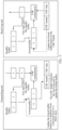
- FIG. 4B shows another data sending and receiving procedure.
- a sending device is a STA and a receiving device is an AP is used, in other words, a Wi-Fi system is used as an example.
- the sending device and the receiving device may communicate through a Wi-Fi link.
- a UDC layer may be added to a communication protocol layer.
- the UDC layer may be added to protocol layers of both the sending device and the receiving device, to implement a UDC function.
- the UDC layer may be located between a logical link control (logical link control, LLC) layer and a MAC layer.
- logical link control logical link control
- the UDC layer may be located between the LLC layer and the MAC layer.
- the UDC layer may be located above the LLC layer.
- feedback may be performed by the LLC layer, and the UDC layer may perform operations such as data receiving and sending by using feedback information of the LLC layer. Therefore, in the Wi-Fi system, the first feedback information in this embodiment of this application may be MAC layer information or LLC layer information.
- the first feedback information is MAC layer information is also used.
- IP internet protocol
- SNAP subnetwork access protocol
- FCS frame check sequence
- a UDC layer may perform UDC compression, based on a UDC buffer (for example, a first buffer), on the data processed by the LLC layer, to obtain compressed data.
- the processed data is the first original data
- the compressed data is the first compressed data in this embodiment of this application.
- the UDC layer may add a UDC header to the compressed data, and the compressed data to which the UDC header is added may be delivered to the MAC layer as a MAC SDU.
- a MAC layer adds a MAC header to the received data, where a MAC address in the MAC header is the same as a MAC address of the LLC layer.
- the MAC layer regenerates an FCS for the data to form an MPDU, and the MPDU is delivered to a physical layer of the sending device for transmission. After receiving the MPDU, the receiving device checks, based on the FCS included in the MPDU, whether the data is correctly received.
- a MAC layer of the receiving device feeds back an ACK to the sending device, and delivers an MSDU corresponding to the MPDU to a UDC layer of the receiving device.
- the UDC layer performs processing such as decompression on the data carried in the MSDU.
- the sending device sends the first compressed data to the receiving device at a first moment.
- the receiving device receives the first compressed data from the sending device at the first moment.
- the "moment" in embodiments of this application may be understood as a time point, or may be understood as a time period.
- the time period is, for example, a subframe (subframe), a slot (slot), a mini-slot (mini-slot), or an orthogonal frequency division multiplexing (orthogonal frequency division multiplexing, OFDM) symbol (symbol).
- the first moment may be a time point, or one or more slots.
- the sending device may further process the first compressed data, and finally send a transmission packet that carries the first compressed data.
- the transmission packet is, for example, a TB.
- the transmission packet is, for example, an MDU.
- the receiving device receives the first compressed data may also be understood as receiving the transmission packet that carries the first compressed data.
- the first compressed data may include one or more pieces of compressed data, where one piece of compressed data may be carried by one transmission packet.
- a plurality of pieces of compressed data may be carried by one transmission packet.
- one piece of compressed data may be carried by a plurality of transmission packets. Therefore, there may be one or more transmission packets used to carry the first compressed data.
- the receiving device sends first feedback information to the sending device at a second moment.
- the sending device receives the first feedback information from the receiving device at the second moment.
- the first feedback information may indicate whether the first compressed data is successfully received or fails to be received.
- the first feedback information is, for example, physical layer feedback information, for example, HARQ feedback information. For example, if the first feedback information is a first value, it indicates that the first compressed data is successfully received; or if the first feedback information is a second value, it indicates that the first compressed data fails to be received.
- the first value is, for example, "1", “true (true)", or "ACK”
- the second value is, for example, "0", “false (false)", or "NACK”.
- an example in which the first value is an ACK and the second value is a NACK is mainly used.
- the sending device may consider that a TB corresponding to a HARQ process corresponding to the ACK has been successfully received by the receiving device. Further, if the TB corresponding to the HARQ process carries compressed data, the sending device may also consider that the compressed data has been successfully received by the receiving device, and the physical layer of the sending device may indicate, to the PDCP layer of the sending device, that the first original data (or the first compressed data) corresponding to the first compressed data has been successfully received.
- the sending device may consider that the receiving device fails to receive a TB corresponding to a HARQ process corresponding to the NACK. Further, if the TB corresponding to the HARQ process carries compressed data, the sending device may also consider that the compressed data fails to be received, and the physical layer of the sending device may indicate, to the PDCP layer of the sending device, that the first original data (or the first compressed data) corresponding to the first compressed data fails to be received.
- whether data corresponding to an uplink data compression technology is successfully received or fails to be received can be fed back by using a feedback mechanism (for example, a physical layer feedback mechanism) corresponding to the first feedback information, without introducing a feedback mechanism of another protocol layer (for example, a PDCP layer), reducing a probability of repeated feedback mechanisms and reducing transmission overheads.
- a feedback mechanism for example, a physical layer feedback mechanism
- another protocol layer for example, a PDCP layer
- the receiving device sends the first feedback information to the sending device for the TB. If the sending device receives first feedback information of a HARQ process corresponding to the TB, the sending device may consider that the first compressed data is successfully received or fails to be received. For example, the first compressed data is transmitted through a TB whose HARQ process number is 3. If the receiving device successfully decodes the TB, the receiving device may send, to the sending device, first feedback information corresponding to the TB, and the first feedback information is an ACK. If the sending device receives the ACK corresponding to the HARQ process number 3, the sending device may determine that the first compressed data is successfully received.
- the receiving device may send, to the sending device, first feedback information corresponding to the TB, and the first feedback information is a NACK. If the sending device receives the NACK corresponding to the HARQ process number 3, the sending device may determine that the first compressed data fails to be received. There may be two cases in which the quantity of TBs used to carry the first compressed data is 1. In one case, the TB is used to carry only the first compressed data, and is not used to carry other compressed data. In this case, the sending device may determine, based on the first feedback information of the HARQ process corresponding to the TB, whether the first compressed data is successfully received or fails to be received.
- the TB is further used to carry other compressed data in addition to the first compressed data.
- the sending device may also determine, based on the first feedback information of the HARQ process corresponding to the TB, whether the first compressed data and the other compressed data are successfully received or fail to be received.
- the receiving device sends first feedback information to the sending device for each of the plurality of TBs.
- the receiving device may send a plurality of pieces of first feedback information for the plurality of TBs. If the sending device receives the plurality of pieces of first feedback information corresponding to the plurality of TBs, the sending device may consider that the first compressed data is successfully received or fails to be received. For example, the first compressed data is transmitted through a TB 1 whose HARQ process number is 3 and a TB 2 whose HARQ process number is 4.
- the receiving device may send first feedback information 1 corresponding to the TB 1 to the sending device, and the first feedback information 1 is an ACK. If the receiving device successfully decodes the TB 2, the receiving device may send first feedback information 2 corresponding to the TB 2 to the sending device, and the first feedback information 2 is an ACK. If the sending device receives the ACK corresponding to the HARQ process number 3 and the ACK corresponding to the HARQ process number 4, the sending device may determine that the first compressed data is successfully received.
- the receiving device may send, to the sending device, first feedback information corresponding to a TB that fails to be decoded, and the first feedback information is a NACK. If the sending device receives the NACK corresponding to the HARQ process number 3 and/or the HARQ process number 4, the sending device may determine that the first compressed data fails to be received.
- a Wi-Fi scenario in which the sending device is a STA and the receiving device is an AP is used as an example. It may be understood that, if the first feedback information is an ACK, the sending device may consider that an MPDU corresponding to the ACK has been successfully received by the receiving device. Further, if the TB carries compressed data, the sending device may also consider that the compressed data has been successfully received by the receiving device, and the MAC layer of the sending device may indicate, to the UDC layer of the sending device, that the first original data (or the first compressed data) corresponding to the first compressed data has been successfully received. Alternatively, if the first feedback information is a NACK, the sending device may consider that the receiving device fails to receive an MPDU corresponding to the NACK.
- the sending device may also consider that the compressed data fails to be received, and the MAC layer of the sending device may indicate, to the UDC layer of the sending device, that the first original data (or the first compressed data) corresponding to the first compressed data fails to be received.
- a feedback mechanism for example, a MAC layer feedback mechanism
- the first feedback information without introducing a feedback mechanism of another protocol layer (for example, a PDCP layer), reducing a probability of repeated feedback mechanisms and reducing transmission overheads.
- the receiving device sends the first feedback information to the sending device for the MPDU. If the sending device receives first feedback information corresponding to the MPDU, the sending device may consider that the first compressed data is successfully received or fails to be received. For example, the first compressed data is transmitted through one MPDU. If the receiving device successfully decodes the MPDU, the receiving device may send, to the sending device, first feedback information corresponding to the MPDU, and the first feedback information is an ACK. If the sending device receives the ACK corresponding to the MPDU, the sending device may determine that the first compressed data is successfully received.
- the receiving device may send, to the sending device, first feedback information corresponding to the MPDU, and the first feedback information is a NACK. If the sending device receives the NACK corresponding to the MPDU, the sending device may determine that the first compressed data fails to be received.
- the quantity of MPDUs used to carry the first compressed data is 1.
- the MPDU is used to carry only the first compressed data, and is not used to carry other compressed data.
- the sending device may determine, based on the first feedback information corresponding to the MPDU, whether the first compressed data is successfully received or fails to be received.
- the MPDU is further used to carry other compressed data in addition to the first compressed data. In this case, the sending device may also determine, based on the first feedback information corresponding to the MPDU, whether the first compressed data and the other compressed data are successfully received or fail to be received.
- the receiving device separately sends first feedback information to the sending device for the plurality of MPDUs. If the sending device receives the first feedback information (including a plurality of pieces of first feedback information) corresponding to the plurality of MPDUs, the sending device may consider that the first compressed data is successfully received or fails to be received. For example, the first compressed data is transmitted through an MPDU 1 and an MPDU 2. If the receiving device successfully decodes the MPDU 1, the receiving device may send first feedback information 1 corresponding to the MPDU 1 to the sending device, and the first feedback information 1 is an ACK.
- the receiving device may send first feedback information 2 corresponding to the MPDU 2 to the sending device, and the first feedback information 2 is an ACK. If the sending device receives the ACK corresponding to the MPDU 1 and the ACK corresponding to the MPDU 2, the sending device may determine that the first compressed data is successfully received. Alternatively, if the receiving device fails to decode either or both of the MPDU 1 or the MPDU 2, the receiving device may send, to the sending device, first feedback information corresponding to an MPDU that fails to be decoded, and the first feedback information is a NACK. If the sending device receives the NACK corresponding to the MPDU 1 and/or the MPDU 2, the sending device may determine that the first compressed data fails to be received.
- the sending device updates the first buffer at a third moment based on the first original data in response to the first feedback information, to obtain a second buffer.
- the second buffer may include the first original data.
- two types of buffers may be provided.
- One type of buffer may be referred to as a standby buffer, and the other type of buffer may be referred to as a formal buffer.
- Both the two types of buffers are buffers corresponding to the UDC technology.
- a buffer used to compress original data is a formal buffer
- a buffer used to store data to be added to the formal buffer is a standby buffer.
- Both the sending device and the receiving device may maintain the two types of buffers.
- a formal buffer of the sending device may be referred to as the first buffer before being updated, for example, before S304 is performed; and the formal buffer may be referred to as the second buffer after being updated, for example, after S304 is performed.
- the to-be-updated formal buffer maintained by the sending device is referred to as the first buffer
- the updated formal buffer is referred to as the second buffer.
- the sending device Before receiving the first feedback information, the sending device cannot determine whether the first original data can be used to update the formal buffer (in this case, the formal buffer is referred to as the first buffer). Therefore, before the sending device receives the first feedback information, the PDCP layer of the sending device may temporarily add the first original data to the standby buffer. If the sending device receives the first feedback information corresponding to the first compressed data, and the first feedback information is an ACK, the physical layer of the sending device may indicate, to the PDCP layer, that the first compressed data is successfully received. In this case, the PDCP layer may extract the first original data in the standby buffer from the standby buffer, and place the first original data in the formal buffer. In this way, the second buffer is obtained. If the sending device needs to compress other original data subsequently, the second buffer may be used for compression.
- the processing process in FIG. 4A is used as an example. If an SN of the first compressed data is 0 (an SN of the first original data is also 0), after operations such as encapsulation and encoding at the RLC layer, the MAC layer, and the PHY layer are performed on the first compressed data, the first compressed data is transmitted through a TB whose HARQ process number is 2. If the receiving device successfully decodes the TB, the receiving device sends an ACK to the sending device for the TB. If the receiving device fails to decode the TB, the receiving device feeds back a NACK to the sending device for the TB.
- the physical layer of the sending device may determine that the first compressed data whose SN is 0 is successfully received. Therefore, the physical layer may notify a layer (for example, the PDCP layer) in which UDC is performed that data whose SN is 0 (or compressed data whose SN is 0 or original data whose SN is 0) may be used for subsequent data compression. In this case, the PDCP layer may extract the original data (for example, the first original data) whose SN is 0 from the standby buffer of the sending device, and add the original data to the first buffer. In this way, the second buffer is obtained.
- a HARQ feedback for example, the first feedback information
- the physical layer of the sending device may determine that the first compressed data whose SN is 0 is successfully received. Therefore, the physical layer may notify a layer (for example, the PDCP layer) in which UDC is performed that data whose SN is 0 (or compressed data whose SN is 0 or original data whose SN is 0) may be used for subsequent
- S305 The receiving device updates a third buffer at a sixth moment based on the first compressed data, to obtain a fourth buffer.
- the receiving device may also maintain a standby buffer and a formal buffer.
- the formal buffer of the receiving device may be referred to as the third buffer before being updated, for example, before S305 is performed; and the formal buffer may be referred to as the fourth buffer after being updated, for example, after S305 is performed.
- the to-be-updated formal buffer maintained by the receiving device is referred to as the third buffer
- the updated formal buffer is referred to as the fourth buffer.
- the third buffer corresponds to the first buffer of the sending device.
- data included in the third buffer is the same as data included in the first buffer.
- the fourth buffer corresponds to the second buffer of the sending device.
- data included in the fourth buffer is the same as data included in the second buffer.
- the sending device may perform S304, and the receiving device may perform S305.
- the sixth moment may be later than the third moment, or may be earlier than the third moment, or may be the same as the third moment. That the receiving device obtains the fourth buffer based on the first compressed data and the third buffer may be understood as that the receiving device obtains the fourth buffer based on the original data corresponding to the first compressed data and the third buffer. For example, the receiving device may add, to the third buffer, the first original data obtained by decompressing the first compressed data, and an obtained buffer is the fourth buffer.
- FIG. 5 is a diagram of working of a formal buffer and a standby buffer in an original data sending process.
- FIG. 5 may correspond to the UDC compression step in the data receiving and sending process shown in FIG. 4A , or may correspond to the UDC compression step in the data receiving and sending process shown in FIG. 4B .
- FIG. 5 is a diagram of working of a formal buffer and a standby buffer in an original data sending process.
- a physical layer feedback corresponding to FIG. 4A
- a MAC layer feedback corresponding to FIG. 4B
- FIG. 5 is applied to the data receiving and sending process shown in FIG. 4A .
- FIG. 5 is applied to the data receiving and sending process shown in FIG. 4B .
- the sending device and the receiving device may update the formal buffer by using different implementation mechanisms. The following describes the implementation mechanisms by using examples.
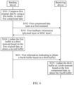
- the sending device sends first information to the receiving device at a fourth moment.
- the receiving device receives the first information from the sending device at the fourth moment.
- the sending device may perform S601.
- the first information may include first indication information.
- the first indication information may indicate the receiving device to obtain the fourth buffer based on the third buffer, or the first indication information may indicate the receiving device to update the third buffer, or the first indication information may indicate the receiving device to obtain the fourth buffer, or the first indication information may indicate the receiving device to update the formal buffer, or the first indication information may indicate the receiving device to update the formal buffer based on the first compressed data (or the first original data).
- the fourth moment may be later than the second moment.
- the first information may further include second indication information, the second indication information may indicate second compressed data, and the second compressed data may be generated based on the second buffer.
- the sending device may continue to compress a next piece of original data by using the second buffer.
- the next piece of original data is second original data, and data obtained by compressing the second original data is referred to as second compressed data.
- the sending device may send the second compressed data to the receiving device.
- the first information may be a data packet including the second compressed data.
- the second indication information includes, for example, an SN of the second compressed data.
- the sending device may include the first indication information to a data packet including a next piece of compressed data, to indicate the receiving device to update the formal buffer, without separately sending the first indication information, effectively improving utilization of the first information. How the first indication information indicates the receiving device to update the formal buffer is described below.
- the receiving device may perform S305. To be specific, after receiving the first information, the receiving device may update the third buffer based on an indication of the first indication information, to obtain the fourth buffer.
- the first information may include the second indication information and the first indication information.
- FIG. 7 is a flowchart of the implementation mechanism.
- the sending device sends first information to the receiving device at a fourth moment.
- the receiving device receives the first information from the sending device at the fourth moment.
- the sending device after performing S303, temporarily does not perform S304, but may perform S701.
- the first information may include first indication information.
- the fourth moment may be later than the second moment.
- the first information may further include second indication information, and the second indication information may indicate second compressed data.
- the second compressed data may be generated based on the first buffer.
- the sending device may continue to compress a next piece of original data by using the first buffer.
- the next piece of original data is second original data, and data obtained by compressing the second original data is referred to as second compressed data.
- the sending device may send the second compressed data to the receiving device.
- the first information may be a data packet including the second compressed data.
- the second indication information includes, for example, an SN of the second compressed data.
- the sending device may include the first indication information to a data packet including a next piece of compressed data, to indicate the receiving device to update the formal buffer, without separately sending the first indication information, effectively improving utilization of the first information. How the first indication information indicates the receiving device to update the formal buffer is described below.
- the receiving device decompresses the second compressed data based on the third buffer.
- the receiving device If the receiving device successfully receives the first information, although the first information indicates the receiving device to update the formal buffer, the receiving device decompresses, by using the third buffer before updating the third buffer, the second compressed data carried in the first information.
- the receiving device may perform S305.
- the receiving device sends second feedback information to the sending device at a fifth moment.
- the sending device receives the second feedback information from the receiving device at the fifth moment.
- the fifth moment may be later than the fourth moment.
- the second feedback information may indicate whether the first information is successfully received or fails to be received. For example, if a value of the second feedback information is a first value, it indicates that the first information is successfully received; or if a value of the second feedback information is a second value, it indicates that the first information fails to be received.
- the second feedback information refer to the foregoing description of the first feedback information.
- the sending device may perform S304.
- the example in FIG. 5 is still used.
- the first information may include the second indication information and the first indication information.
- a moment at which the receiving device sends a physical layer feedback is usually later than a moment at which the receiving device receives compressed data. Therefore, for the foregoing second implementation mechanism, occasions for updating the formal buffers by the receiving device and the sending device may be inconsistent.
- An SL scenario in which both the sending device and the receiving device are UEs is used as an example.
- the HARQ feedback needs to be transmitted at an interval of at least two slots.
- the HARQ feedback can be sent at least on a physical sidelink feedback channel (physical sidelink feedback channel, PSFCH) in a slot T3. Therefore, the sending device can update the formal buffer at least in the slot T3.
- the receiving device may be able to update the formal buffer in a slot T1 or a slot T2. It can be learned that occasions for updating the formal buffers by the receiving device and the sending device are inconsistent. Consequently, the formal buffers of the two ends cannot be aligned, and a decompression failure may be caused.
- the receiving device may wait first duration before updating a formal buffer.
- the sending device may also wait the first duration before updating the formal buffer.
- a unit of the first duration is, for example, a subframe, a slot, an OFDM symbol, or a millisecond.
- a timer may be configured for each of the sending device and the receiving device.
- the timer of the sending device is referred to as a first timer
- the timer of the receiving device is referred to as a second timer.
- Timing duration of the first timer may be equal to timing duration of the second timer.
- the timing duration is, for example, the first duration.
- An end moment of the first duration is, for example, the third moment, and a start moment of the first duration is, for example, the fourth moment or the fifth moment.
- the third moment may be later than or equal to a moment obtained by adding the first duration to the fourth moment, or the third moment may be later than or equal to a moment obtained by adding the first duration to the fifth moment. If the end moment of the first duration is the third moment, and the start moment of the first duration is the fourth moment, for the receiving device, the first duration may indicate a delay between a moment at which the receiving device receives the first indication information and a moment at which the first indication information actually takes effect (that is, the receiving device updates the third buffer).
- the first duration may indicate a delay between a moment at which the receiving device sends, to the sending device, a physical layer feedback or a MAC layer feedback corresponding to a transmission packet (for example, a TB or an MPDU) that carries the first indication information and a moment at which the first indication information actually takes effect.
- a transmission packet for example, a TB or an MPDU
- the first duration may be configured by the sending device and notified to the receiving device, or may be configured by the receiving device and notified to the sending device, or may be predefined in a protocol, or may be preconfigured in the sending device and the receiving device. That the first duration is configured by the sending device and notified to the receiving device is used as an example.
- the sending device may send second information to the receiving device, and the second information may indicate the first duration.
- the second information may be sent in a semi-static manner.
- the second information may be carried in a radio resource control (radio resource control, RRC) message.
- RRC radio resource control
- the second information may be valid in second duration, where the second duration is, for example, greater than or equal to the first duration; or the second information may be valid in one or more slots; or the second information may be valid in one or more OFDM symbols.
- the second information may be sent in another manner.
- the second information may be sent by using signaling such as a MAC control element (control element, CE).
- the start moment of the first duration is the fourth moment
- the end moment of the first duration is the third moment.
- the first duration is five slots. Still refer to FIG. 8 .
- a start moment of the slot T1 is the fourth moment.
- the receiving device does not update the formal buffer immediately, but waits five slots before updating the formal buffer.
- the receiving device may update the formal buffer when a 5 th slot (a slot T5) arrives.
- the receiving device may update the formal buffer when a last OFDM symbol in the slot T5 ends, or may update the formal buffer at a start time domain position of a 1 st OFDM symbol in a slot T6.
- an end time domain position of the last OFDM symbol in the slot T5 or the start time domain position of the 1 st OFDM symbol in the slot T6 is the third moment.
- the receiving device may update the formal buffer when a 5 th slot (a slot T6) arrives.
- the receiving device may update the formal buffer when a last OFDM symbol of the T6 slot ends, or may update the formal buffer at a start time domain position of a 1 st OFDM symbol of a slot T7.
- a mechanism of updating the formal buffer by the sending device is similar to that of the receiving device.
- the start moment of the first duration is the fifth moment
- the end moment of the first duration is the third moment.
- the first duration is five slots. Still refer to FIG. 8 .
- the receiving device may send a physical layer feedback or a MAC layer feedback to the sending device in the slot T4, to indicate that the data packet is successfully received.
- the receiving device does not update the formal buffer immediately, but waits five slots before updating the formal buffer.
- the receiving device may update the formal buffer when a 5 th slot (a slot T8) arrives.
- the receiving device may update the formal buffer when a last OFDM symbol of the slot T8 ends, or may update the formal buffer at a start time domain position of a 1 st OFDM symbol of a slot T9.
- a mechanism of updating the formal buffer by the sending device is similar to that of the receiving device.
- the sending device sends a piece of compressed data in the slot T3
- the compressed data needs to be compressed by using a to-be-updated formal buffer
- the receiving device needs to decompress the compressed data by using a to-be-updated formal buffer. It can be learned that, because the occasions for updating the formal buffers of the receiving end and the transmitting end are aligned, the formal buffers of the receiving end and the transmitting end may be consistent. This helps improve a success rate of compression and decompression.
- the first indication information may indicate the receiving device to update the formal buffer.
- the first indication information may indicate the first compressed data, to indirectly indicate the receiving device to update the formal buffer based on the first compressed data.
- the first indication information may indicate the first compressed data in a plurality of different indication manners. The following describes some optional manners by using examples.
- the first indication information may indicate a sequence number of the first compressed data, for example, an SN of the first compressed data.
- the first indication information includes the sequence number of the first compressed data. If the first compressed data includes a plurality of pieces of compressed data, that the first indication information includes the sequence number of the first compressed data may indicate that the first indication information includes sequence numbers of some or all of the plurality of pieces of compressed data.
- the first indication information includes the sequence number of the first compressed data.
- the following describes a manner in which the first indication information includes the sequence number of the first compressed data by using an example in which the first indication information is included in a UDC header of the first information.
- the first indication information includes sequence numbers of all pieces of compressed data in the first compressed data.
- the first compressed data may include one or more pieces of compressed data, and the first indication information may include sequence numbers of all the pieces of compressed data. This indication manner is clear, in which the receiving device may directly obtain the sequence numbers of all the pieces of compressed data included in the first compressed data.
- FIG. 9A is a diagram of a PDCP header and a UDC header.
- the UDC header may be included in the first information, and the UDC header may include the first indication information.
- the UDC header in FIG. 9A has newly added fields.
- the newly added fields are collectively referred to as a first field.
- the first field may include at least one field, and the first field may be used to carry the first indication information.
- one field is used to carry one piece of information, which may also be described as that the field includes the information.
- the first field is used to carry a sequence number of compressed data, which may also be described as that the first field includes the sequence number of the compressed data.
- an SL scenario in which both the sending device and the receiving device are UEs is used as an example.
- the first field includes a field shown by "PDCP SN update (update)" in FIG. 9A
- the PDCP SN update field may be used to carry the sequence numbers of all the pieces of compressed data included in the first compressed data.
- a length of the PDCP SN update field in FIG. 9A is merely an example. In actual application, the length of the PDCP SN update field may be extended based on lengths of the sequence numbers of all the pieces of compressed data included in the first compressed data.
- the first field may further include a first indication field.
- the first indication field is, for example, a "U" field in the UDC header in FIG. 9A .
- the U field may indicate whether to update the formal buffer.
- the first information may indicate, by using the U field, whether to update the formal buffer. If the U field indicates to update the formal buffer, the PDCP SN update field is used to indicate compressed data through which the formal buffer is updated. For example, if a value of the U field is "1", it indicates to update the formal buffer; or if the value of the U field is "0", it indicates not to update the formal buffer. If the U field indicates to update the formal buffer, PDCP SN update may carry a PDCP SN of compressed data used to update the formal buffer. If the U field indicates not to update the formal buffer, PDCP SN update may be empty, or the PDCP SN update field may not exist, to reduce overheads of the UDC header.
- the U field may not exist. If the PDCP SN update field carries a PDCP SN, it indicates to update the formal buffer based on the compressed data corresponding to the PDCP SN. If the PDCP SN update field does not carry a PDCP SN (for example, the PDCP SN update field is empty), or the PDCP SN update field does not exist, it indicates not to update the formal buffer.
- the PDCP header in FIG. 9A includes a PDCP SN field that is used to carry a PDCP SN of compressed data newly sent this time.
- a PDCP SN field that is used to carry a PDCP SN of compressed data newly sent this time.
- FIG. 9B is a diagram of another UDC header.
- the UDC header may be included in the first information, and the UDC header may carry the first indication information.
- New fields are added to the UDC header in FIG. 9B .
- the newly added fields are collectively referred to as a first field.
- the first field may include at least one field, and the first field may be used to carry the first indication information.
- a Wi-Fi scenario in which the sending device is a STA and the receiving device is an AP is used as an example.
- the first field includes a field shown by "SN update" in FIG. 9B
- the SN update field may be used to carry the sequence numbers of all the pieces of compressed data included in the first compressed data.
- a length of the SN update field in FIG. 9B is merely an example. In actual application, the length of the SN update field may be extended based on lengths of the sequence numbers of all the pieces of compressed data included in the first compressed data.
- the first field may further include a first indication field, for example, a "U" field in the UDC header in FIG. 9B .
- a first indication field for example, a "U" field in the UDC header in FIG. 9B .
- U field For a description of the U field, refer to the foregoing description.
- the PDCP header in FIG. 9B includes an SN field that is used to carry an SN of compressed data newly sent this time.
- an SN field that is used to carry an SN of compressed data newly sent this time.
- the first indication information includes a sequence number of a last piece of compressed data in the first compressed data. For example, if the first compressed data includes M pieces of compressed data, the first indication information may include a sequence number of a last piece of compressed data in the M pieces of compressed data, and M is a positive integer. The last piece of compressed data in the M pieces of compressed data is a last piece of compressed data that is in the M pieces of compressed data and that is sorted by sequence number.
- FIG. 9A An SL scenario in which both the sending device and the receiving device are UEs is used as an example. Still refer to FIG. 9A .
- the PDCP SN update field in FIG. 9A does not carry the sequence numbers of all the pieces of compressed data included in the first compressed data, but carries the sequence number of the last piece of compressed data in the M pieces of compressed data, in other words, PDCP SN update carries only one PDCP SN. In this way, overheads of the UDC header can be effectively reduced.
- the manner A1 For more descriptions (for example, the U field and the PDCP header) of the manner A2, refer to the manner A1.
- a Wi-Fi scenario in which the sending device is a STA and the receiving device is an AP is used as an example. Still refer to FIG. 9B .
- the SN update field in FIG. 9B does not carry the sequence numbers of all the pieces of compressed data included in the first compressed data, but carries the sequence number of the last piece of compressed data in the M pieces of compressed data, in other words, the SN update carries only one SN. In this way, overheads of the UDC header can be effectively reduced.
- the manner A1 For more descriptions (for example, the U field and the PDCP header) of the manner A2, refer to the manner A1.
- the first compressed data includes M pieces of compressed data, the M pieces of compressed data belong to K groups, and the first indication information includes a sequence number of a 1 st piece of compressed data in each of the K groups and a sequence number of a last piece of compressed data in each of the K groups.
- K is a positive integer.
- a 1 st piece of compressed data in a group of compressed data is a 1 st piece of compressed data that is in the group of compressed data and that is sorted by sequence number.
- a last piece of compressed data in a group of compressed data is a last piece of compressed data that is in the group of compressed data and that is sorted by sequence number.
- a first field is added to the UDC header, the first field includes K groups of fields, and the K groups of fields may carry the first indication information.
- one group of fields may carry sequence numbers of one group of compressed data.
- a group of fields in the K groups of fields may include a start field and an end field. The start field may carry a sequence number of a 1 st piece of compressed data in a group of compressed data, and the end field may carry a sequence number of a last piece of compressed data in the group of compressed data.
- FIG. 9C is a diagram of a PDCP header and a UDC header.
- the UDC header may be included in the first information, and the UDC header may carry the first indication information.
- an SL scenario in which both the sending device and the receiving device are UEs is used as an example.
- an example in which the first compressed data includes two groups of compressed data is used. Therefore, an example in which a first field includes two groups of fields is also used.
- a first group of fields in the first field includes a 1 st PDCP SN start (start) field from top to bottom and a 1 st PDCP SN end (end) field from top to bottom.
- a second group of fields in the first field includes a 2 nd PDCP SN start field from top to bottom and a 2 nd PDCP SN end field from top to bottom.
- the first group of fields is used as an example.
- the first group of fields may further include a second indication field.
- the second indication field is, for example, located between the PDCP SN start field and the PDCP SN end field, and includes, for example, an "E" field in FIG. 9C .
- the second indication field may indicate whether the UDC header further includes a sequence number of compressed data used to update the formal buffer, or indicate whether the UDC header further includes a next group of fields used to update the formal buffer.
- a value of the E field is "1" it indicates that the UDC header further includes the sequence number of the compressed data used to update the formal buffer, and the receiving device may continue decoding. If the value of the E field is "0", it indicates that the UDC header does not include the sequence number of the compressed data used to update the formal buffer, and the receiving device does not need to continue decoding.
- a value of an E field namely, a 1 st E field from top to bottom
- a value of an E field namely, a 2 nd E field from top to bottom
- a value of the 1 st E field is "1”. Therefore, the receiving device further continues to decode the UDC header.
- FIG. 9D is a diagram of another UDC header.
- the UDC header may be included in the first information, and the UDC header may carry the first indication information.
- a Wi-Fi scenario in which the sending device is a STA and the receiving device is an AP is used as an example.
- the first compressed data includes two groups of compressed data is used. Therefore, an example in which a first field includes two groups of fields is also used.
- a first group of fields in the first field includes a 1 st SN start field from top to bottom and a 1 st SN end field from top to bottom.
- a second group of fields in the first field includes a 2 nd SN start field from top to bottom and a 2 nd SN end field from top to bottom.
- the first field may further include a second indication field.
- the second indication field is, for example, located between the first group of fields and the second group of fields, and includes, for example, an "E" field in FIG. 9D .
- the second indication field may indicate whether the UDC header further includes a sequence number of compressed data used to update the formal buffer, or indicate whether the UDC header further includes a next group of fields used to update the formal buffer. For example, if a value of the E field is "1", it indicates that the UDC header further includes the sequence number of the compressed data used to update the formal buffer, and the receiving device may continue decoding.
- a value of a 1 st E field is "1”. Therefore, the receiving device further continues to decode the UDC header.
- the first field may be improved, to reduce overheads of the UDC header.
- the first field still includes K groups of fields, and a group of fields in the K groups of fields may include a start field and an end field.
- the K groups of fields further include K 1 groups of fields (K 1 is a positive integer less than K).
- a group of fields in the K 1 groups of fields may include a sequence number field.
- the sequence number field may carry a sequence number of a group of compressed data that includes only one piece of compressed data. In other words, the sequence number field needs to carry a sequence number of only one piece of compressed data.
- FIG. 9E is a diagram of a PDCP header and a UDC header.
- the UDC header may be included in the first information, and the UDC header may carry the first indication information.
- an SL scenario in which both the sending device and the receiving device are UEs is used as an example.
- an example in which the first compressed data includes two groups of compressed data is used. Therefore, an example in which a first field includes two groups of fields is also used.
- a first group of fields in the first field includes a 1 st PDCP SN start field from top to bottom and a 1 st PDCP SN end field from top to bottom.
- the group of fields may further include a third indication field, and the third indication field is, for example, located between the PDCP SN start field and the PDCP SN end field.
- the third indication field may include a first indication subfield and a second indication subfield.
- the first indication subfield is, for example, a 1 st "E1" field from top to bottom in FIG. 9E
- the second indication subfield is, for example, a 1 st "E2" field from top to bottom in FIG. 9E .
- the first indication subfield may indicate whether the UDC header further includes sequence numbers of a group of compressed data used to update the formal buffer, or indicate whether the UDC header further includes a group of start fields and end fields.
- the second indication subfield may indicate whether the UDC header further includes a sequence number of a piece of compressed data used to update the formal buffer, or indicate whether the UDC header further includes a sequence number field. For example, if a value of the E1 field is "1", it indicates that the UDC header further includes a group of start fields and end fields; or if the value of the E1 field is "0", it indicates that the UDC header does not include a group of start fields and end fields. For example, if a value of the E2 field is "1", it indicates that the UDC header further includes a sequence number field; or if the value of the E2 field is "0", it indicates that the UDC header does not include a sequence number field.
- different groups of fields included in the first field in FIG. 9E may have different formats, and therefore may be separately indicated by different indication subfields.
- a quantity of types of fields included in the first field may be equal to a quantity of indication subfields included in the third indication field.
- the E1 field and the E2 field may be replaced with the E field in FIG. 9C , to indicate whether the UDC header further includes a group of fields, without distinguishing a type of the group of fields.
- a second group of fields in the first field includes a 2 nd PDCP SN field from top to bottom.
- the second group of fields may further include a fourth indication field, and the fourth indication field is, for example, located after the PDCP SN field.
- the fourth indication field may include a third indication subfield and a fourth indication subfield.
- the third indication subfield is, for example, a 2 nd "E1" field from top to bottom in FIG. 9E
- the fourth indication subfield is, for example, a 2 nd "E2" field from top to bottom in FIG. 9E .
- the value of the 1 st E1 field is "0”
- the value of the 1 st E2 field is "1".
- the receiving device further continues to decode the UDC header.
- FIG. 9F is a diagram of another UDC header.
- the UDC header may be included in the first information, and the UDC header may carry the first indication information.
- a Wi-Fi scenario in which the sending device is a STA and the receiving device is an AP is used as an example.
- the first compressed data includes three groups of compressed data is used. Therefore, an example in which a first field includes three groups of fields is also used. For example, a first group of fields in the first field includes a 1 st SN start field from top to bottom and a 1 st SN end field from top to bottom.
- a second group of fields in the first field includes a 2 nd SN start field from top to bottom and a 2 nd SN end field from top to bottom.
- a third group of fields in the first field includes a 2 nd SN field from top to bottom.
- the first field may further include a third indication field.
- the third indication field includes, for example, a field located between the first group of fields and the second group of fields, and includes, for example, a 1 st "E1" field and a 1 st "E2" field from top to bottom in FIG. 9F .
- the first field may further include a fourth indication field.
- the fourth indication field is, for example, located between the second group of fields and the third group of fields, and includes, for example, a 2 nd "E1" field and a 2 nd "E2" field from top to bottom in FIG. 9F .
- the third indication field indicates the second group of fields, and the fourth indication field indicates the third group of fields.
- the value of the 1 st E1 field is "1”
- the value of the 1 st E2 field is "0".
- the receiving device further continues to decode the UDC header.
- the first indication field may indicate a type of the first group of fields included in the first field.
- the first indication field may include a U field and an R field in FIG. 9E or FIG. 9F .
- the two fields are combined as the first indication field. For example, if a value of the first indication field is "00", it indicates that the first group of fields does not exist, and the receiving device does not need to continue decoding. If the value of the first indication field is "01", it indicates that a type of the first group of fields is a start field and an end field.
- the first indication field indicates that a type of the first group of fields is a sequence number field.
- the first indication field may be used to indicate whether the first group of fields exists, or may be used to indicate a type of the first group of fields, so that the indication manner is more flexible.
- the first field also includes a plurality of types of fields, a similar implementation may also be used for the first indication field. This is not limited.
- the first compressed data includes M pieces of compressed data, the M pieces of compressed data belong to K groups, and the first indication information includes a sequence number of a 1 st piece of compressed data that is in each of the K groups and that is sorted by sequence number, and includes an offset between the 1 st piece of compressed data and a last piece of compressed data that is in each of the K groups and that is sorted based on the sequence numbers.
- K is a positive integer. In this embodiment of this application, and the two features may be replaced with each other. Details are not described below.
- a first field is added to the UDC header, the first field includes K groups of fields, and the K groups of fields may carry the first indication information.
- a group of fields in the K groups of fields may include a start field and an offset field.
- the start field may carry a sequence number of a 1 st piece of compressed data in a group of compressed data
- the offset field may carry an offset between a last piece of compressed data in a group of compressed data and a 1 st piece of compressed data in the group of compressed data.
- the manner A1 the manner A3, or the manner A4 may be used. If the manner A3 or the manner A4 is used, overheads of the UDC header can be reduced in comparison with the manner A1. If the manner A4 is used, overheads of the UDC header can be further reduced in comparison with the manner A3.
- FIG. 9G is a diagram of a PDCP header and a UDC header.
- the UDC header may be included in the first information, and the UDC header may carry the first indication information.
- an SL scenario in which both the sending device and the receiving device are UEs is used as an example.
- an example in which the first compressed data includes two groups of compressed data is used. Therefore, an example in which a first field includes two groups of fields is also used.
- a first group of fields in the first field includes a 1 st PDCP SN start field from top to bottom and a 1 st PDCP SN offset (offset) field from top to bottom.
- a second group of fields in the first field includes a 2 nd PDCP SN start field from top to bottom and a 2 nd PDCP SN offset field from top to bottom.
- the first group of fields is used as an example.
- the group of fields may further include a fifth indication field.
- the fifth indication field is, for example, located between the PDCP SN start field and the PDCP SN offset field, and includes, for example, an "E" field in FIG. 9G .
- For the fifth indication field refer to the foregoing description of the first indication field.
- Content included in the second group of fields is similar, and details are not described again. For example, if the two groups of fields in FIG.
- a value of an E field (namely, a 1 st E field from top to bottom) in the first group of fields may be "1”
- a value of an E field (namely, a 1 st E field from top to bottom) in the second group of fields may be "0”.
- the PDCP SN offset field in the first group of fields may carry 3, and a value of a 1 st E field is "1". Therefore, the receiving device further continues to decode the UDC header.
- the PDCP SN offset field in the second group of fields may carry 0, and a value of a 2 nd E field is "0".
- FIG. 9H is a diagram of another UDC header.
- the UDC header may be included in the first information, and the UDC header may carry the first indication information.
- a Wi-Fi scenario in which the sending device is a STA and the receiving device is an AP is used as an example.
- the first compressed data includes two groups of compressed data is used. Therefore, an example in which a first field includes two groups of fields is also used.
- a first group of fields in the first field includes a 1 st SN start field from top to bottom and a 1 st SN offset field from top to bottom.
- a second group of fields in the first field includes a 2 nd SN start field from top to bottom and a 2 nd SN offset field from top to bottom.
- the first field may further include a sixth indication field.
- the sixth indication field is, for example, located between the first group of fields and the second group of fields, and includes, for example, a 1 st "E" field from top to bottom in FIG. 9H .
- the first field may further include a seventh indication field.
- the seventh indication field is, for example, located between the second group of fields and a third group of fields, and includes, for example, a 2 nd "E" field from top to bottom in FIG. 9H .
- the sixth indication field indicates the second group of fields, and the seventh indication field indicates the third group of fields. For content such as indication manners of these fields, refer to the foregoing description.
- the SN offset field in the first group of fields may carry 3, and a value of the 1 st E field is "1". Therefore, the receiving device further continues to decode the UDC header.
- the SN offset field in the second group of fields may carry 0, and a value of the 2 nd E field is "0". Therefore, the receiving device stops decoding the UDC header.
- the first field may further include a field used to carry a single SN.
- FIG. 9G may be extended to further include a sequence number field used to carry a single SN.
- the PDCP SN end field in FIG. 9E may be replaced with a PDCP SN offset field.
- FIG. 9H may be extended to further include a sequence number field used to carry a single SN.
- the SN end field in FIG. 9F may be replaced with an SN offset field.
- a group of fields in the K groups of fields may include an offset field and an end field.
- the offset field may carry an offset between a 1 st piece of compressed data in a group of compressed data and a last piece of compressed data in the group of compressed data
- the end field may carry a sequence number of a last piece of compressed data in a group of compressed data. Details are not described again.
- the first compressed data includes M pieces of compressed data
- the first indication information includes sequence numbers of a 1 st piece of compressed data and a last piece of compressed data that are in N pieces of compressed data and that are sorted by sequence number, and further includes sequence numbers of some or all of N-M pieces of compressed data.
- the sequence numbers of the N pieces of compressed data are consecutive, the N pieces of compressed data include the M pieces of compressed data, M is a positive integer less than or equal to N, and N is a positive integer.
- a first field is added to the UDC header, the first field includes K groups of fields, and the K groups of fields may carry the first indication information.
- An i th group of fields in the K groups of fields may include a start field and an end field.
- the start field may carry the sequence number of the 1 st piece of compressed data in the N pieces of compressed data
- the end field may carry the sequence number of the last piece of compressed data in the N pieces of compressed data.
- an i th group of fields in the K groups of fields may include a start field and an offset field.
- the start field may carry the sequence number of the 1 st piece of compressed data in the N pieces of compressed data
- the offset field may carry an offset between the last piece of compressed data and the 1 st piece of compressed data in the N pieces of compressed data.
- the i th group of fields is, for example, a first group of fields in the K groups of fields, or may be any group of fields in the K groups of fields.
- the K groups of fields further include K-1 groups of fields.
- the K-1 groups of fields may indicate the N-M pieces of compressed data.
- the K-1 groups of fields may carry sequence numbers of some or all of the N-M pieces of compressed data.
- the N-M pieces of compressed data are further divided into H groups of compressed data based on continuity of sequence numbers, where H is a positive integer.
- the K-1 groups of fields carry sequence numbers of some or all of the H groups of compressed data.
- a carrying manner refer to any one of the manner A1 to the manner A4.
- the i th group of fields indicates the N pieces of compressed data
- the K-1 groups of fields indicate the compressed data (namely, the N-M pieces of compressed data) that needs to be removed from the N pieces of compressed data.
- the N pieces of compressed data are indicated by the K groups of fields.
- the first indication information may indicate an offset of the first compressed data.
- the first information may further include second indication information
- the second indication information may indicate second compressed data
- the second compressed data is, for example, compressed data that is newly sent to the receiving device this time.
- the offset that is of the first compressed data and indicated by the first indication information is, for example, an offset between a sequence number of the first compressed data and a sequence number of the second compressed data, or an offset between the sequence number of the first compressed data and a sequence number of a last piece of compressed data stored in a current UDC buffer (for example, the first buffer or the third buffer).
- FIG. 9I is a diagram of a PDCP header and a UDC header.
- the UDC header may be included in the first information, and the UDC header may carry the first indication information and the second indication information.
- an SL scenario in which both the sending device and the receiving device are UEs is used as an example.
- a PDCP SN field in FIG. 9I is used to carry the second indication information, and the second indication information includes, for example, a PDCP SN of the second compressed data.
- a PDCP SN offset field in FIG. 9I may be used to carry the first indication information, and the first indication information includes, for example, an offset between a PDCP SN of the first compressed data and the PDCP SN of the second compressed data.
- Other offsets in this embodiment of this application may also be processed similarly. For other content of FIG. 9I , refer to the description of FIG. 9A .
- FIG. 9J is a diagram of another UDC header.
- the UDC header may be included in the first information, and the UDC header may carry the first indication information and the second indication information.
- a Wi-Fi scenario in which the sending device is a STA and the receiving device is an AP is used as an example.
- an SN field in FIG. 9J is used to carry the second indication information, and the second indication information includes, for example, an SN of the second compressed data.
- An SN offset field in FIG. 9J may be used to carry the first indication information, and the first indication information includes, for example, an offset between an SN of the first compressed data and the SN of the second compressed data.
- the description of FIG. 9B refer to the description of FIG. 9B .
- the first indication information may indicate the first compressed data in another manner. This is not limited in embodiments of this application.
- whether data corresponding to the UDC technology is successfully received or fails to be received can be fed back by using a feedback mechanism corresponding to the first feedback information, without introducing a feedback mechanism of another protocol layer (for example, a PDCP layer), reducing feedback resource overheads when ensuring transmission reliability.
- the sending device may indicate, in various manners, the compressed data used to update the formal buffer. This is flexible.
- FIG. 10 is a diagram of a structure of a communication apparatus according to an embodiment of this application.
- the communication apparatus 1000 may be the sending device in the embodiment shown in any one of FIG. 3 , FIG. 6 , or FIG. 7 or a circuit system of the sending device, and is configured to implement the method corresponding to the sending device in the foregoing method embodiments.
- the communication apparatus 1000 may be the receiving device in the embodiment shown in any one of FIG. 3 , FIG. 6 , or FIG. 7 or a circuit system of the receiving device, and is configured to implement the method corresponding to the receiving device in the foregoing method embodiments.
- a circuit system is a chip system.
- the communication apparatus 1000 includes at least one processor 1001.
- the processor 1001 may be configured to perform internal processing of the apparatus, to implement a specific control processing function.
- the processor 1001 includes instructions.
- the processor 1001 may store data.
- different processors may be independent components, may be located at different physical locations, or may be located on different integrated circuits.
- different processors may be integrated into one or more processors, for example, integrated into one or more integrated circuits.
- the communication apparatus 1000 includes one or more memories 1003, configured to store instructions.
- the memory 1003 may further store data.
- the processor and the memory may be separately disposed, or may be integrated together.
- the communication apparatus 1000 includes a communication line 1002 and at least one communication interface 1004.
- the memory 1003, the communication line 1002, and the communication interface 1004 are all optional, and therefore are all represented by dashed lines in FIG. 10 .
- the communication apparatus 1000 may further include a transceiver and/or an antenna.
- the transceiver may be configured to send information to another apparatus or receive information from another apparatus.
- the transceiver may be referred to as a transceiver machine, a transceiver circuit, an input/output interface, or the like, and is configured to implement receiving and sending functions of the communication apparatus 1000 by using an antenna.
- the transceiver includes a transmitter (transmitter) and a receiver (receiver).
- the transmitter may be configured to generate a radio frequency (radio frequency) signal based on a baseband signal
- the receiver may be configured to convert the radio frequency signal into the baseband signal.
- the processor 1001 may include a general-purpose central processing unit (central processing unit, CPU), a microprocessor, an application-specific integrated circuit (application-specific integrated circuit, ASIC), or one or more integrated circuits configured to control program execution in the solutions of this application.
- CPU central processing unit
- ASIC application-specific integrated circuit
- the communication line 1002 may include a path for transmitting information between the foregoing components.
- the communication interface 1004 may be any apparatus like a transceiver, and is configured to communicate with another device or a communication network, such as Ethernet, a radio access network (radio access network, RAN), a wireless local area network (wireless local area network, WLAN), or a wired access network.
- a radio access network radio access network, RAN
- a wireless local area network wireless local area network, WLAN
- the memory 1003 may be a read-only memory (read-only memory, ROM) or another type of static storage device that can store static information and instructions, or a random access memory (random access memory, RAM) or another type of dynamic storage device that can store information and instructions, or may be an electrically erasable programmable read-only memory (electrically erasable programmable read-only memory, EEPROM), a compact disc read-only memory (compact disc read-only memory, CD-ROM) or another optical disc storage, an optical disc storage (including a compact optical disc, a laser disc, an optical disc, a digital versatile optical disc, a blue optical disc, and the like), a magnetic disk storage medium or another magnetic storage device, or any other medium that can carry or store expected program code in an instruction or data structure form and can be accessed by a computer, but is not limited thereto.
- the memory 1003 may exist alone, and is connected to the processor 1001 through the communication line 1002. Alternatively, the memory 1003 may be integrated with the processor 1001.
- the memory 1003 is configured to store computer-executable instructions for executing the solutions of this application, and the processor 1001 controls the execution.
- the processor 1001 is configured to execute the computer-executable instructions stored in the memory 1003, to implement the steps performed by the sending device in the embodiment shown in any one of FIG. 3 , FIG. 6 , or FIG. 7 , or implement the steps performed by the receiving device in the embodiment shown in any one of FIG. 3 , FIG. 6 , or FIG. 7 .
- the computer-executable instructions in this embodiment of this application may also be referred to as application program code. This is not specifically limited in this embodiment of this application.
- the processor 1001 may include one or more CPUs, such as a CPU 0 and a CPU 1 in FIG. 10 .
- the communication apparatus 1000 may include a plurality of processors such as the processor 1001 and a processor 1005 in FIG. 10 .
- Each of the processors may be a single-core (single-CPU) processor, or may be a multi-core (multi-CPU) processor.
- the processor herein may be one or more devices, circuits, and/or processing cores configured to process data (for example, computer program instructions).
- the chip includes the processor 1001 (and may further include the processor 1005), the communication line 1002, the memory 1003, and the communication interface 1004.
- the communication interface 1004 may be an input interface, a pin, a circuit, or the like.
- the memory 1003 may be a register, a buffer, or the like.
- the processor 1001 and the processor 1005 may be a general-purpose CPU, a microprocessor, an ASIC, or one or more integrated circuits configured to control program execution of the communication method in any one of the foregoing embodiments.
- the apparatus may be divided into functional modules based on the foregoing method examples.
- each functional module may be obtained through division based on each corresponding function, or two or more functions may be integrated into one processing module.
- the integrated module may be implemented in a form of hardware, or may be implemented in a form of a software functional module.
- module division is an example, and is merely a logical function division. In actual implementation, another division manner may be used.
- FIG. 11 is a diagram of an apparatus.
- the apparatus 1100 may be the sending device or the receiving device in the foregoing method embodiments, or a chip in the sending device or a chip in the receiving device.
- the apparatus 1100 includes a sending unit 1101, a processing unit 1102, and a receiving unit 1103.
- the apparatus 1100 may be configured to implement the steps performed by the sending device or the receiving device in the communication method in embodiments of this application.
- the apparatus 1100 may be configured to implement the steps performed by the sending device or the receiving device in the communication method in embodiments of this application.
- functions/implementation processes of the sending unit 1101, the receiving unit 1103, and the processing unit 1102 in FIG. 11 may be implemented by the processor 1001 in FIG. 10 by invoking the computer-executable instructions stored in the memory 1003.
- functions/implementation processes of the processing unit 1102 in FIG. 11 may be implemented by the processor 1001 in FIG. 10 by invoking the computer-executable instructions stored in the memory 1003, and functions/implementation processes of the sending unit 1101 and the receiving unit 1103 in FIG. 11 may be implemented through the communication interface 1004 in FIG. 10 .
- functions/implementation processes of the sending unit 1101 and the receiving unit 1103 may alternatively be implemented by a pin, a circuit, or the like.
- This application further provides a computer-readable storage medium.
- the computer-readable storage medium stores a computer program or instructions, and when the computer program or the instructions are run, the method performed by the sending device or the receiving device according to the foregoing method embodiments is implemented.
- the functions in the foregoing embodiments may be implemented in a form of a software functional unit and sold or used as an independent product.
- the technical solutions of this application essentially, or the part contributing to conventional technologies, or a part of the technical solutions may be implemented in a form of a software product.
- the computer software product is stored in a storage medium, and includes several instructions for instructing a computer device (which may be a personal computer, a server, a network device, or the like) to perform all or a part of the steps of the methods described in embodiments of this application.
- the storage medium includes any medium that can store program code, such as a USB flash drive, a removable hard disk, a ROM, a RAM, a magnetic disk, or an optical disc.
- the computer program product includes computer program code.
- the computer program code When the computer program code is run on a computer, the computer is enabled to perform the method performed by the sending device or the receiving device in any one of the foregoing method embodiments.
- An embodiment of this application further provides a processing apparatus, including a processor and an interface.
- the processor is configured to perform the method performed by the sending device or the receiving device in any one of the foregoing method embodiments.
- All or some of the foregoing embodiments may be implemented by using software, hardware, firmware, or any combination thereof.
- software is used to implement the embodiments, all or a part of the embodiments may be implemented in a form of a computer program product.
- the computer program product includes one or more computer instructions.
- the computer may be a general-purpose computer, a dedicated computer, a computer network, or another programmable apparatus.
- the computer instructions may be stored in a computer-readable storage medium or may be transmitted from a computer-readable storage medium to another computer-readable storage medium.
- the computer instructions may be transmitted from a website, computer, server, or data center to another website, computer, server, or data center in a wired (for example, a coaxial cable, an optical fiber, or a digital subscriber line (DSL)) or wireless (for example, infrared, radio, or microwave) manner.
- the computer-readable storage medium may be any usable medium accessible by the computer, or a data storage device, for example, a server or a data center, integrating one or more usable media.
- the usable medium may be a magnetic medium (for example, a floppy disk, a hard disk, or a magnetic tape), an optical medium (for example, a DVD), a semiconductor medium (for example, a solid state disk, (solid state disk, SSD)), or the like.
- a magnetic medium for example, a floppy disk, a hard disk, or a magnetic tape
- an optical medium for example, a DVD
- a semiconductor medium for example, a solid state disk, (solid state disk, SSD)
- Various illustrative logic units and circuits described in embodiments of this application may implement or operate the described functions by using a general-purpose processor, a digital signal processor (digital signal processor, DSP), an application-specific integrated circuit (application-specific integrated circuit, ASIC), a field-programmable gate array (field-programmable gate array, FPGA) or another programmable logic apparatus, a discrete gate or transistor logic, a discrete hardware part, or a design of any combination of the foregoing devices.
- the general-purpose processor may be a microprocessor.
- the general-purpose processor may also be any conventional processor, controller, microcontroller, or state machine.
- the processor may alternatively be implemented by a combination of computing apparatuses, such as a digital signal processor and a microprocessor, multiple microprocessors, one or more microprocessors with a digital signal processor core, or any other similar configuration.
- Steps of the methods or algorithms described in embodiments of this application may be directly embedded into hardware, a software unit executed by a processor, or a combination thereof.
- the software unit may be stored in a RAM, a flash memory, a ROM, an erasable programmable read-only memory (erasable programmable read-only memory, EPROM), an EEPROM, a register, a hard disk, a removable magnetic disk, a CD-ROM, or any other form of storage medium in the art.
- the storage medium may connect to a processor, so that the processor can read information from the storage medium and write information into the storage medium.
- the storage medium may be integrated into a processor.
- the processor and the storage medium may be disposed in an ASIC, and the ASIC may be disposed in a terminal device.
- the processor and the storage medium may be disposed in different parts of a terminal device.
- These computer program instructions may also be loaded onto a computer or another programmable data processing device, so that a series of operations and steps are performed on the computer or the another programmable device, thereby generating computer-implemented processing. Therefore, the instructions executed on the computer or the another programmable device provide steps for implementing a specific function in one or more processes in the flowcharts and/or in one or more blocks in the block diagrams.
- the sending device and/or the receiving device may perform some or all steps in embodiments of this application. These steps or operations are merely examples. In embodiments of this application, other operations or variations of various operations may be further performed. In addition, the steps may be performed in a sequence different from a sequence presented in embodiments of this application, and not all operations in embodiments of this application need to be performed.
Landscapes
- Engineering & Computer Science (AREA)
- Computer Networks & Wireless Communication (AREA)
- Signal Processing (AREA)
- Computer Security & Cryptography (AREA)
- Mobile Radio Communication Systems (AREA)
Applications Claiming Priority (3)
| Application Number | Priority Date | Filing Date | Title |
|---|---|---|---|
| CN202210538050 | 2022-05-17 | ||
| CN202210827300.1A CN117134865A (zh) | 2022-05-17 | 2022-07-13 | 一种通信方法及装置 |
| PCT/CN2023/093204 WO2023221832A2 (zh) | 2022-05-17 | 2023-05-10 | 一种通信方法及装置 |
Publications (2)
| Publication Number | Publication Date |
|---|---|
| EP4518209A2 true EP4518209A2 (de) | 2025-03-05 |
| EP4518209A4 EP4518209A4 (de) | 2025-07-02 |
Family
ID=88834556
Family Applications (1)
| Application Number | Title | Priority Date | Filing Date |
|---|---|---|---|
| EP23806784.7A Pending EP4518209A4 (de) | 2022-05-17 | 2023-05-10 | Kommunikationsverfahren und -vorrichtung |
Country Status (2)
| Country | Link |
|---|---|
| EP (1) | EP4518209A4 (de) |
| WO (1) | WO2023221832A2 (de) |
Family Cites Families (5)
| Publication number | Priority date | Publication date | Assignee | Title |
|---|---|---|---|---|
| CN107094142B (zh) * | 2017-04-28 | 2020-11-27 | 电信科学技术研究院 | 一种上行数据解压缩、压缩的方法和装置 |
| US11122462B2 (en) * | 2018-11-06 | 2021-09-14 | Samsung Electronics Co., Ltd. | Method and system for handling checksum error in uplink data compression |
| CN111510419B (zh) * | 2019-01-31 | 2021-03-30 | 华为技术有限公司 | 一种数据压缩的方法及基站 |
| CN112218390A (zh) * | 2019-07-10 | 2021-01-12 | 大唐移动通信设备有限公司 | 数据处理的方法和设备 |
| CN112333769B (zh) * | 2019-08-05 | 2022-10-11 | 华为技术有限公司 | 一种通信方法和装置 |
-
2023
- 2023-05-10 WO PCT/CN2023/093204 patent/WO2023221832A2/zh not_active Ceased
- 2023-05-10 EP EP23806784.7A patent/EP4518209A4/de active Pending
Also Published As
| Publication number | Publication date |
|---|---|
| EP4518209A4 (de) | 2025-07-02 |
| WO2023221832A3 (zh) | 2024-01-11 |
| WO2023221832A2 (zh) | 2023-11-23 |
Similar Documents
| Publication | Publication Date | Title |
|---|---|---|
| US8988994B2 (en) | System and method for creating logical radio link control (RLC) and medium access control (MAC) protocol data units (PDUs) in mobile communication system | |
| US12261694B2 (en) | Terminal device based on downlink data processing accelerator | |
| CN107005560B (zh) | 一种数据发送方法、数据接收方法和相关设备 | |
| US12348309B2 (en) | Data processing method and apparatus | |
| EP4554280A1 (de) | Datenverarbeitungsverfahren und -vorrichtung | |
| US10469210B2 (en) | Acknowledgment data unit for data unit fragment | |
| CN107404734A (zh) | 数据发送方法、装置及系统 | |
| WO2017185941A1 (zh) | 一种数据传输方法及相关设备 | |
| EP4311300A1 (de) | Datenübertragungsverfahren und -vorrichtung | |
| EP4145899A1 (de) | Verfahren zur meldung des funkverbindungssteuerstatus und entsprechende vorrichtung | |
| US20200145145A1 (en) | Acknowledgment data unit for data unit fragment | |
| WO2024021982A1 (zh) | 通信方法及装置 | |
| CN115918149A (zh) | 用于数据平面的级联和预处理的系统和方法 | |
| US9794930B1 (en) | Method and apparatus for packet data unit processing for retransmission | |
| EP4661485A1 (de) | Kommunikationsverfahren und zugehörige vorrichtung | |
| CN110506436A (zh) | 无线通信装置、无线通信方法及无线通信系统 | |
| CN117134865A (zh) | 一种通信方法及装置 | |
| WO2023221832A2 (zh) | 一种通信方法及装置 | |
| CN111416689B (zh) | 数据传输方法及通信设备 | |
| EP3413665A1 (de) | Basisstationsvorrichtung, kommunikationsendgerät, kommunikationssystem, programm, rahmenübertragungsverfahren und datenstruktur | |
| EP4693981A1 (de) | Kommunikationsverfahren und kommunikationsvorrichtung | |
| WO2019095228A1 (en) | Method, apparatus and computer program | |
| EP4576926A1 (de) | Datenübertragungsverfahren und -vorrichtung | |
| CN109983824A (zh) | 数据传输方法、装置及存储介质 | |
| CN121751247A (zh) | 通信方法及应用装置 |
Legal Events
| Date | Code | Title | Description |
|---|---|---|---|
| STAA | Information on the status of an ep patent application or granted ep patent |
Free format text: STATUS: THE INTERNATIONAL PUBLICATION HAS BEEN MADE |
|
| PUAI | Public reference made under article 153(3) epc to a published international application that has entered the european phase |
Free format text: ORIGINAL CODE: 0009012 |
|
| STAA | Information on the status of an ep patent application or granted ep patent |
Free format text: STATUS: REQUEST FOR EXAMINATION WAS MADE |
|
| 17P | Request for examination filed |
Effective date: 20241127 |
|
| AK | Designated contracting states |
Kind code of ref document: A2 Designated state(s): AL AT BE BG CH CY CZ DE DK EE ES FI FR GB GR HR HU IE IS IT LI LT LU LV MC ME MK MT NL NO PL PT RO RS SE SI SK SM TR |
|
| REG | Reference to a national code |
Ref country code: DE Ref legal event code: R079 Free format text: PREVIOUS MAIN CLASS: H04L0001160000 Ipc: H04L0069040000 |
|
| A4 | Supplementary search report drawn up and despatched |
Effective date: 20250530 |
|
| RIC1 | Information provided on ipc code assigned before grant |
Ipc: H04W 28/14 20090101ALI20250523BHEP Ipc: H04W 28/06 20090101ALI20250523BHEP Ipc: H04L 1/1867 20230101ALI20250523BHEP Ipc: H04L 1/1829 20230101ALI20250523BHEP Ipc: H04L 1/1822 20230101ALI20250523BHEP Ipc: H04L 69/04 20220101AFI20250523BHEP |
|
| DAV | Request for validation of the european patent (deleted) | ||
| DAX | Request for extension of the european patent (deleted) | ||
| GRAP | Despatch of communication of intention to grant a patent |
Free format text: ORIGINAL CODE: EPIDOSNIGR1 |
|
| STAA | Information on the status of an ep patent application or granted ep patent |
Free format text: STATUS: GRANT OF PATENT IS INTENDED |