EP4518178A1 - Vorrichtung und verfahren zur durchführung von ai/ml-basierter strahlverwaltung in einem drahtloskommunikationssystem - Google Patents
Vorrichtung und verfahren zur durchführung von ai/ml-basierter strahlverwaltung in einem drahtloskommunikationssystem Download PDFInfo
- Publication number
- EP4518178A1 EP4518178A1 EP23796795.5A EP23796795A EP4518178A1 EP 4518178 A1 EP4518178 A1 EP 4518178A1 EP 23796795 A EP23796795 A EP 23796795A EP 4518178 A1 EP4518178 A1 EP 4518178A1
- Authority
- EP
- European Patent Office
- Prior art keywords
- ssbris
- cris
- rsrp
- sinr
- report
- Prior art date
- Legal status (The legal status is an assumption and is not a legal conclusion. Google has not performed a legal analysis and makes no representation as to the accuracy of the status listed.)
- Pending
Links
Images


Classifications
-
- H—ELECTRICITY
- H04—ELECTRIC COMMUNICATION TECHNIQUE
- H04B—TRANSMISSION
- H04B7/00—Radio transmission systems, i.e. using radiation field
- H04B7/02—Diversity systems; Multi-antenna system, i.e. transmission or reception using multiple antennas
- H04B7/04—Diversity systems; Multi-antenna system, i.e. transmission or reception using multiple antennas using two or more spaced independent antennas
- H04B7/06—Diversity systems; Multi-antenna system, i.e. transmission or reception using multiple antennas using two or more spaced independent antennas at the transmitting station
- H04B7/0686—Hybrid systems, i.e. switching and simultaneous transmission
- H04B7/0695—Hybrid systems, i.e. switching and simultaneous transmission using beam selection
- H04B7/06952—Selecting one or more beams from a plurality of beams, e.g. beam training, management or sweeping
-
- G—PHYSICS
- G06—COMPUTING OR CALCULATING; COUNTING
- G06N—COMPUTING ARRANGEMENTS BASED ON SPECIFIC COMPUTATIONAL MODELS
- G06N20/00—Machine learning
-
- G—PHYSICS
- G06—COMPUTING OR CALCULATING; COUNTING
- G06N—COMPUTING ARRANGEMENTS BASED ON SPECIFIC COMPUTATIONAL MODELS
- G06N3/00—Computing arrangements based on biological models
- G06N3/02—Neural networks
- G06N3/04—Architecture, e.g. interconnection topology
-
- G—PHYSICS
- G06—COMPUTING OR CALCULATING; COUNTING
- G06N—COMPUTING ARRANGEMENTS BASED ON SPECIFIC COMPUTATIONAL MODELS
- G06N3/00—Computing arrangements based on biological models
- G06N3/02—Neural networks
- G06N3/04—Architecture, e.g. interconnection topology
- G06N3/045—Combinations of networks
-
- H—ELECTRICITY
- H04—ELECTRIC COMMUNICATION TECHNIQUE
- H04L—TRANSMISSION OF DIGITAL INFORMATION, e.g. TELEGRAPHIC COMMUNICATION
- H04L5/00—Arrangements affording multiple use of the transmission path
- H04L5/003—Arrangements for allocating sub-channels of the transmission path
- H04L5/0048—Allocation of pilot signals, i.e. of signals known to the receiver
- H04L5/005—Allocation of pilot signals, i.e. of signals known to the receiver of common pilots, i.e. pilots destined for multiple users or terminals
-
- H—ELECTRICITY
- H04—ELECTRIC COMMUNICATION TECHNIQUE
- H04L—TRANSMISSION OF DIGITAL INFORMATION, e.g. TELEGRAPHIC COMMUNICATION
- H04L5/00—Arrangements affording multiple use of the transmission path
- H04L5/003—Arrangements for allocating sub-channels of the transmission path
- H04L5/0053—Allocation of signalling, i.e. of overhead other than pilot signals
- H04L5/0057—Physical resource allocation for CQI
-
- H—ELECTRICITY
- H04—ELECTRIC COMMUNICATION TECHNIQUE
- H04W—WIRELESS COMMUNICATION NETWORKS
- H04W24/00—Supervisory, monitoring or testing arrangements
- H04W24/02—Arrangements for optimising operational condition
-
- H—ELECTRICITY
- H04—ELECTRIC COMMUNICATION TECHNIQUE
- H04W—WIRELESS COMMUNICATION NETWORKS
- H04W24/00—Supervisory, monitoring or testing arrangements
- H04W24/10—Scheduling measurement reports ; Arrangements for measurement reports
Definitions
- the present disclosure relates to a device and method for performing artificial intelligence/machine learning (AI/ML) based beam management in a wireless communication system. More specifically, the present disclosure relates to a method for a user equipment (UE) to report information capable of mainly using as an input parameter of base station AI/ML and a device and method for performing a beam report through UE AI/ML in AI/ML based beam management in a wireless communication system.
- UE user equipment
- the present disclosure describes a method for a UE to report information capable of mainly using as an input parameter of BS AI/ML in AI/ML-based beam management and a beam reporting method through UE AI/ML.
- the present disclosure proposes a beam reporting operation of a UE for AI/ML-based beam management.
- the present disclosure provides a device and method for performing artificial intelligence/machine learning (AI/ML) based beam management in a wireless communication system.
- AI/ML artificial intelligence/machine learning
- the present disclosure provides a method for a user equipment (UE) to report information capable of mainly using as an input parameter of base station (BS) AI/ML and a device and method for performing a beam report through UE AI/ML in AI/ML based beam management in a wireless communication system.
- UE user equipment
- a method of operating a user equipment (UE) in a wireless communication system comprising receiving a channel state information (CSI) resource configuration from a base station, receiving a plurality of CSI-reference signals (RSs) from the base station based on a plurality of first CSI-reference signal resource indicators (CRIs) or a plurality of first synchronization signal block resource indicators (SSBRIs) related to the CSI resource configuration, measuring a received signal received power (RSRP) or a signal to interference power (SINR) related to the first CRIs or the first SSBRIs, calculating a derivative value per time unit of the measured RSRP or SINR, selecting a predetermined number of second CRIs or second SSBRIs from among the first CRIs or the first SSBRIs based on an absolute value and the derivative value of the RSRP or the SINR, and transmitting, to the base station, a report message related to the second CRIs or the second CSI resource configuration from a base station, receiving a
- a method of operating a base station in a wireless communication system comprising transmitting a channel state information (CSI) resource configuration to a user equipment (UE), transmitting a plurality of CSI-reference signals (RSs) to the UE based on a plurality of first CSI-reference signal resource indicators (CRIs) or a plurality of first synchronization signal block resource indicators (SSBRIs) related to the CSI resource configuration, and receiving, from the UE, a report message related to second CRIs or second SSBRIs which are a part of the first CRIs or the first SSBRIs, wherein the second CRIs or the second SSBRIs are a predetermined number of CRIs or SSBRIs selected based on an absolute value of a received signal received power (RSRP) or a signal to interference power (SINR) related to the first CRIs or the first SSBRIs and a derivative value per time unit of the RSRP
- RSRP received signal received power
- a user equipment in a wireless communication system, the UE comprising a transceiver, at least one processor, and at least one memory operably connectable to the at least one processor and configured to store instructions performing operations based on being executed by the at least one processor, wherein the operations comprise all steps of a method of operating the UE according to various embodiments of the present disclosure.
- a base station in a wireless communication system comprising a transceiver, at least one processor, and at least one memory operably connectable to the at least one processor and configured to store instructions performing operations based on being executed by the at least one processor, wherein the operations comprise all steps of a method of operating the base station according to various embodiments of the present disclosure.
- a control device controlling a user equipment (UE) in a wireless communication system
- the control device comprising at least one processor and at least one memory operably connectable to the at least one processor, wherein the at least one memory is configured to store instructions performing operations based on being executed by the at least one processor, and the operations comprise all steps of a method of operating the UE according to various embodiments of the present disclosure.
- a control device controlling a base station in a wireless communication system
- the control device comprising at least one processor and at least one memory operably connectable to the at least one processor, wherein the at least one memory is configured to store instructions performing operations based on being executed by the at least one processor, and the operations comprise all steps of a method of operating the base station according to various embodiments of the present disclosure.
- one or more non-transitory computer readable mediums storing one or more instructions, wherein the one or more instructions are configured to perform operations based on being executed by one or more processors, and the operations comprise all steps of a method of operating a user equipment (UE) according to various embodiments of the present disclosure.
- UE user equipment
- one or more non-transitory computer readable mediums storing one or more instructions, wherein the one or more instructions are configured to perform operations based on being executed by one or more processors, and the operations comprise all steps of a method of operating a base station according to various embodiments of the present disclosure.
- the present disclosure can provide a device and method for performing artificial intelligence/machine learning (AI/ML) based beam management in a wireless communication system.
- AI/ML artificial intelligence/machine learning
- the present disclosure can provide a method for a user equipment (UE) to report information capable of mainly using as an input parameter of base station (BS) AI/ML and a device and method for performing a beam report through UE AI/ML in AI/ML based beam management in a wireless communication system.
- UE user equipment
- a or B may mean “only A,” “only B” or “both A and B.” In other words, in various embodiments of the present disclosure, “A or B” may be interpreted as “A and/or B.” For example, in various embodiments of the present disclosure, “A, B or C” may mean “only A,” “only B,” “only C” or "any combination of A, B and C.”
- a slash (/) or comma used in various embodiments of the present disclosure may mean “and/or.”
- A/B may mean “A and/or B.”
- A/B may mean “only A,” “only B” or “both A and B.”
- A, B, C may mean “A, B, or C.”
- At least one of A and B may mean “only A,” “only B” or “both A and B.”
- the expression of "at least one of A or B” or “at least one of A and/or B” may be interpreted in the same meaning as "at least one of A and B.”
- At least one of A, B, and C may mean “only A,” “only B,” “only C” or “any combination of A, B and C.”
- at least one of A, B or C or “at least one of A, B and/or C” may mean “at least one of A, B, and C.”
- parentheses used in various embodiments of the present disclosure may mean “for example.” Specifically, when “control information (PDCCH)" is described, “PDCCH” may be proposed as an example of “control information.” In other words, “control information” in various embodiments of the present disclosure is not limited to “PDCCH,” and “PDDCH” may be proposed as an example of "control information.” In addition, even when “control information (i.e., PDCCH)" is described, “PDCCH” may be proposed as an example of "control information.”
- downlink means communication from a base station (BS) to a terminal
- uplink means communication from the terminal to the base station.
- a transmitter may be part of the base station, and a receiver may be part of the terminal.
- the transmitter may be part of the terminal, and the receiver may be part of the base station.
- the base station may be expressed as a first communication device, and the terminal may be expressed as a second communication device.
- the base station may be replaced with terms including a fixed station, a Node B, an evolved-NodeB (eNB), a next generation NodeB (gNB), a base transceiver system (BTS), an access point (AP), a network (5G network), an artificial intelligence (AI) system/module, a road side unit (RSU), a robot, an unmanned aerial vehicle (UAV), an augmented reality (AR) device, a virtual reality (VR) device, and the like.
- a fixed station a Node B, an evolved-NodeB (eNB), a next generation NodeB (gNB), a base transceiver system (BTS), an access point (AP), a network (5G network), an artificial intelligence (AI) system/module, a road side unit (RSU), a robot, an unmanned aerial vehicle (UAV), an augmented reality (AR) device, a virtual reality (VR) device, and the like.
- eNB evolved-NodeB
- gNB next generation NodeB
- the terminal may be fixed or mobile and may be replaced with terms including a user equipment (UE), a mobile station (MS), a user terminal (UT), a mobile subscriber station (MSS), a subscriber station (SS), an advanced mobile station (AMS), a wireless terminal (WT), a machine-type communication (MTC) device, a machine-to-machine (M2M) device, and a device-to-device (D2D) device, a vehicle, a road side unit (RSU), a robot, an AI module, an unmanned aerial vehicle (UAV), an augmented reality (AR) device, a virtual reality (VR) device, and the like.
- UE user equipment
- MS mobile station
- UT mobile subscriber station
- SS subscriber station
- AMS advanced mobile station
- WT wireless terminal
- MTC machine-type communication
- M2M machine-to-machine
- D2D device-to-device
- vehicle a vehicle, a road side unit (RSU), a robot, an AI
- the following technology may be used in various radio access system including CDMA, FDMA, TDMA, OFDMA, SC-FDMA, and the like.
- the CDMA may be implemented as radio technology such as Universal Terrestrial Radio Access (UTRA) or CDMA2000.
- the TDMA may be implemented as radio technology such as a global system for mobile communications (GSM)/general packet radio service (GPRS)/enhanced data rates for GSM evolution (EDGE).
- GSM global system for mobile communications
- GPRS general packet radio service
- EDGE enhanced data rates for GSM evolution
- the OFDMA may be implemented as radio technology such as Institute of Electrical and Electronics Engineers (IEEE) 802.11 (Wi-Fi), IEEE 802.16 (WiMAX), IEEE 802.20, Evolved UTRA (E-UTRA), or the like.
- the UTRA is a part of Universal Mobile Telecommunications System (UMTS).
- 3rd Generation Partnership Project (3GPP) Long Term Evolution (LTE) is a part of Evolved UMTS (E-UMTS) using the E-UTRA and LTE-Advanced (A)/LTE-A pro is an evolved version of the 3GPP LTE.
- 3GPP NR New Radio or New Radio Access Technology
- 3GPP LTE/LTE-A/LTE-A pro is an evolved version of the 3GPP LTE/LTE-A/LTE-A pro.
- LTE means technology after 3GPP TS 36.xxx Release 8.
- LTE technology after 3GPP TS 36.xxx Release 10 is referred to as the LTE-A
- LTE technology after 3GPP TS 36.xxx Release 13 is referred to as the LTE-A pro.
- the 3GPP NR means technology after TS 38.xxx Release 15.
- the LTE/NR may be referred to as a 3GPP system.
- "xxx" means a detailed standard document number.
- the LTE/NR may be collectively referred to as the 3GPP system.
- the three main use cases for evaluating performance improvement using the AI/ML have been presented to be CSI reporting, beam management, and positioning.
- the AI/ML-based operation between the BS and the UE may be simply divided into a BS AI/ML operation, a UE AI/ML operation, and a BS-UE joint AI/ML operation.
- the present disclosure describes a method for a UE to report information capable of mainly using as an input parameter of BS AI/ML in AI/ML-based beam management and a beam reporting method through UE AI/ML.
- the present disclosure proposes a beam reporting operation of a UE for AI/ML-based beam management.
- downlink means communication from a base station (BS) to a terminal
- uplink means communication from the terminal to the base station.
- a transmitter may be part of the base station, and a receiver may be part of the terminal.
- the transmitter may be part of the terminal, and the receiver may be part of the base station.
- the base station may be expressed as a first communication device, and the terminal may be expressed as a second communication device.
- the base station may be replaced with terms including a fixed station, a Node B, an evolved-NodeB (eNB), a next generation NodeB (gNB), a base transceiver system (BTS), an access point (AP), a network (5G network), an artificial intelligence (AI) system/module, a road side unit (RSU), a robot, an unmanned aerial vehicle (UAV), an augmented reality (AR) device, a virtual reality (VR) device, and the like.
- a fixed station a Node B, an evolved-NodeB (eNB), a next generation NodeB (gNB), a base transceiver system (BTS), an access point (AP), a network (5G network), an artificial intelligence (AI) system/module, a road side unit (RSU), a robot, an unmanned aerial vehicle (UAV), an augmented reality (AR) device, a virtual reality (VR) device, and the like.
- eNB evolved-NodeB
- gNB next generation NodeB
- the terminal may be fixed or mobile and may be replaced with terms including a user equipment (UE), a mobile station (MS), a user terminal (UT), a mobile subscriber station (MSS), a subscriber station (SS), an advanced mobile station (AMS), a wireless terminal (WT), a machine-type communication (MTC) device, a machine-to-machine (M2M) device, and a device-to-device (D2D) device, a vehicle, a road side unit (RSU), a robot, an AI module, an unmanned aerial vehicle (UAV), an augmented reality (AR) device, a virtual reality (VR) device, and the like.
- UE user equipment
- MS mobile station
- UT mobile subscriber station
- SS subscriber station
- AMS advanced mobile station
- WT wireless terminal
- MTC machine-type communication
- M2M machine-to-machine
- D2D device-to-device
- vehicle a vehicle, a road side unit (RSU), a robot, an AI
- the BM procedure as layer 1 (L1)/layer 2 (L2) procedures for obtaining and maintaining a set of base station (e.g., gNB, TRP, etc.) and/or terminal (e.g., UE) beams available for downlink (DL) and uplink (UL) transmission/reception, may include the following procedures and terms.
- the BM procedure may be divided into (1) a DL BM procedure using synchronization signal (SS)/physical broadcast channel (PBCH) block or CSI-RS, and (2) an UL BM procedure using a sounding reference signal (SRS).
- SS synchronization signal
- PBCH physical broadcast channel
- SRS sounding reference signal
- each BM procedure may include Tx beam sweeping for determining the Tx beam and RX beam sweeping for determining the Rx beam.
- a TCI state may be used to configure/indicate an Rx beam (i.e., spatial Rx parameter) to be used when a base station receives PDCCH and PDSCH from a UE using the quasi co-located (QCL) concept introduced in (Rel-15) NR (more specifically, when the base station receives DMRS of PDCCH and PDSCH from the UE). It may be indicated to use the Rx beam when receiving the DL RS configured as a reference upon the PDCCH or PDSCH reception by configuring/updating a DL reference signal (e.g., SSB-RI, CRI(P/SP/AP)) as a reference RS or a source RS of a QCL Type-D component through the TCI state.
- a DL reference signal e.g., SSB-RI, CRI(P/SP/AP)
- spatialRelationInfo may be used to configure/indicate a Tx beam to be used when a base station transmits an UL channel to a UE.
- the base station transmits PUCCH and SRS by configuring/updating a DL reference signal (i.e., SSB-RI, CRI(P/SP/AP)) or an SRS (i.e., SRS resource) as a reference RS for a target UL channel and/or a target RS via RRC configuration and/or MAC CE activation
- the base station may indicate which UL Tx beam (i.e., spatial Tx parameter) is used.
- a Tx beam that is configured/updated/indicated by the base station and is used for SRS transmission is indicated as a Tx beam for the PUSCH via an SRI field of UL grant DCI and is used as a PUSCH Tx beam of the UE.
- a TCI state configuration may be used to configure/indicate an Rx beam for target DL RS/channel.
- a UE Rx beam can be configured by configuring a QCL type-D RS at an RRC/MAC CE level (through TCI state ID configuration within a TCI state pool).
- the target DL RS/channel is PDCCH, a specific TCI state ID is indicated via MAC CE after configuring up to 64 TCI state IDs to a specific CORESET, and thus the UE Rx beam can be configured, and the Rx beam of the corresponding CORESET can be updated through the same MAC CE massage.
- the PDSCH Rx beam can be indicated through the TCI indication upon DL scheduling by connecting up to 8 TCI state IDs to a TCI state field of DL DCI (within up to 128 TCI state pools) via MAC CE, and the PDSCH Rx beam can be updated by updating the TCI state IDs connected to the TCI state field through the same MAC CE massage.
- the Tx beam can be configured by connecting PUCCH-SpatialRelationInfoId to each PUCCH resource through the MAC CE message in order to configure/indicate the PUCCH Tx beam, and an MAC level for PUCCH-SpatialRelationInfo can be updated through the same MAC CE message.
- SRS-SpatialRelationInfo of SRS resources in a corresponding semi-persistent SRS resource set can be updated through the MAC CE message that activates transmission of SRS for SP-SRS.
- the operation between the BS and the UE has been enhanced to enable update of SRS-SpatialRelationInfo of SRS resources in a corresponding aperiodic SRS resource set through the MAC CE message for AP-SRS.
- the operation between the BS and the UE has been enhanced to enable the simultaneous update of spatial relation reference RSs in multiple CCs (BWPs) for the SP-SRS and the AP-SRS through the MAC CE message.
- BWPs CCs
- the operation between the BS and the UE has been enhanced to enable the simultaneous spatial relation update for PUSCH resources in the PUCCH resource group.
- NR Rel-15/Rel-16 higher layer signaling such as RRC and MAC CE is mainly used for a beam indication/update operation for reception/transmission between a BS and a UE, and a DCI based beam indication operation has been supported for some channels/RSs (PDSCH, PUSCH), etc.
- PDSCH DL/UL TCI
- PUSCH PUSCH
- a dynamic beam update operation using a joint DL/UL TCI state and a separate DL/UL TCI state is introduced, and the base station has standardized a UE common beam update operation that performs a common indication/update of a plurality of UE-specific channel/RS combinations to one beam by using DCI.
- Target channels/RSs of the common beam update may include UE-dedicated CORESET and UE-dedicated reception on PDSCH in the case of DL, and DG/CG-PUSCH and all or subset of dedicated PUCCHs in the case of UL.
- AP CSI-RS for tracking/BM and SRS may be configured for the target channels/RSs.
- one feature corresponds to the content agreed upon as a working assumption and is defined as a UE capability value set index (hereinafter referred to as C-ID for short), and how many C-IDs the UE has is reported to the UE as a UE capability report.
- C-ID UE capability value set index
- the attribute to be included in the C-IDs agreed upon so far is the maximum number of SRS ports supported by the UE for each C-ID. That is, the C-ID is defined only for panel(s) with different SRS port numbers.
- Another feature is an operation of (instantaneous/periodic) report by including the C-IDs reported as the UE capability in the beam report as captured in the agreement.
- this evolved reporting method will be hereinafter referred to as 'panel-specific beam report'.
- RS indices i.e., CRI or SSBRI
- N is a value between 1 and 4 and is set by the base station
- L1-RSRP or L1-SINR value which is a reception quality value of the corresponding RSs.
- the panel-specific beam report method will report the optimal C-ID (for each CRI/SSBRI) along with the L1-RSRP/L1-SINR(s) related to the CRI/SSBRI(s).
- a mode for individually reporting C-ID for each CRI/SSBRI and/or a mode for reporting a single C-ID for all the CRIs/SSBRIs will be supported.
- Working Assumption Support the UE reporting a list of UE capability value sets - Each UE capability value set comprises the max supported number of SRS ports - For any two different value sets, at least one capability value needs to be different ⁇ FFS: If in addition also identical value sets are allowed.
- the UE capability value set can be common across all BWPs/CCs in same band or BC can be discussed in UE feature session Agreement On Rel.17 enhancements to facilitate UE -initiated panel activation and selection via UE reporting a list of UE capability value sets, the correspondence between each reported CSI-RS and/or SSB resource index and one of the UE capability value sets in the reported list is determined by the UE (analogous to Rel-15/16) and is informed to NW in a beam reporting instance. - The Rel-15/16 beam reporting framework is used, i.e.
- the index of corresponding UE capability value set is reported along with the pair of SSBRI/CRI and L1-RSRP/SINR (up to 4 pairs, with 7-bit absolute and 4-bit differential) in the beam reporting UCI and down select (maintenance) between the following two-options:
- ⁇ Option 2 UE can report one index for each reported CRI/SSBRI in one beam reporting.
- ⁇ FFS whether/how to take DL-only panel into account in the report - FFS: Time-domain behaviour, e.g.
- ⁇ FFS Semi-persistent and/or aperiodic reporting is triggered only when periodic reporting is configured - (Working assumptions): Support acknowledgement mechanism of the reported correspondence from NW to UE, which doesn't preclude reusing/reinterpreting existing signaling/procedure ⁇ FFS (maintenance): the application time for the reported correspondence (if any), the exact acknowledgement mechanism and whether spec impact is needed, e.g. based on TCI state update, BFR response like mechanism, including the application time for the reported correspondence, if any ⁇ No new DCI format and no new RNTI are introduced for this function.
- the power control configuration/indication for the UE of the base station is performed by configuration per UL channel/RS (i.e., PUSCH, PUCCH, SRS).
- PUSCH Physical Uplink Control Channel
- PUCCH Physical Uplink Control Channel
- SRS Physical Uplink Control Channel
- a PL-RS (configured for path-loss calculation) is either included in UL TCI state or (if applicable) joint TCI state or associated with UL TCI state or (if applicable) joint TCI state.
- a UE supports "beam misalignment or not" (detailed definition FFS) between the DL source RS in the UL or (if applicable) joint TCI state to provide spatial relation indication and the PL-RS is a UE capability ⁇
- the term "beam misalignment” is for discussion purpose only • Whether it is 'included in' or 'associated with' (including the manner it is performed and the signaling) is up to RAN2 •
- the UE maintains the PL-RS of the activated UL TCI state or (if applicable) joint TCI state •
- the maximum number of activated UL TCI states or (if applicable) joint TCI states per band per cell is a UE capability •
- FFS detailed aspects of PL-RS, e.g.
- Each setting can be associated with at least one TCI state, and, for a given TCI state, only one setting for PUSCH and only one setting for PUCCH can be associated at a time.
- ⁇ Working Assumption
- each of the activated UL or (if applicable) joint TCI states is associated with one of the settings.
- the setting(s) of (P0, alpha, closed loop index) per channel/signal per BWP is independent of the UL or (if applicable) joint TCI states • FFS: If the setting of (P0, alpha, closed loop index) for SRS can also be associated with UL or (if applicable) joint TCI state.
- FFS (to be decided in RAN1#106-e) whether to configure the same setting of (P0, alpha, closed loop index) per TCI state across channels and apply a channel dependent component, or configure a channel dependent setting of (P0, alpha, closed loop index) per TCI state Agreement
- the setting of (P0, alpha, closed loop index) for SRS can also be associated with UL or (if applicable) joint TCI state.
- a pathloss reference RS (hereinafter referred to as PL-RS) has been standardized so that it is associated with or included in the joint TCI state and/or UL TCI state (association/including is determined in the RAN2).
- the power control parameters (P0, alpha, closed-loop index) other than the PL-RS have been standardized so that they are associated with the joint TCI state and/or the UL TCI state. That is, due to the Rel-17 MIMO standardization, the base station may configure/indicate the UL Tx beam for a specific target DL/UL channel/RS of the UE through the joint and/or separate UL TCI states and also configure/indicate the power control parameters required for determining the transmission power.
- FIG. 1 illustrates an example of a concept related to deep learning based artificial intelligence (AI) in a system applicable to the present disclosure.
- AI artificial intelligence
- node(s) and UE(s) constituting a wireless communication network are becoming more intelligent/advanced.
- various network/base station decision parameter values e.g., transmission/reception power of each BS, transmission power of each UE, precoder/beam of BS/UE, time/frequency resource allocation for each UE, duplex method of each BS, etc.
- various environmental parameters e.g., distribution/location of base stations, distribution/location/material of buildings/furniture, etc., location/movement direction/speed of UEs, climate information, etc.
- AI/ML may be easily referred to as artificial intelligence based on deep learning in a narrow sense, but conceptually, it is as shown in table below.
- Representative models of deep learning include a feed-forward neural network (FFNN), a recurrent neural network (RNN), a convolution neural network (CNN), and an auto encoder.
- FFNN feed-forward neural network
- RNN recurrent neural network
- CNN convolution neural network
- auto encoder an auto encoder
- FIG. 2 illustrates an example of a structure of a feed-forward neural network (FFNN) as an example of a deep learning model in a system applicable to the present disclosure.
- FFNN feed-forward neural network
- It consists of an input layer, a hidden layer, and an output layer.
- FIG. 3 illustrates an example of a structure of a recurrent neural network (RNN) as an example of a deep learning model in a system applicable to the present disclosure.
- RNN recurrent neural network
- RNN is a type of artificial neural network in which hidden nodes are connected to directed edges to form a directed cycle. It is a model suitable for processing data that sequentially appears, such as voice and text.
- LSTM long short-term memory
- FIG. 4 illustrates an example of a structure of a convolution neural network (CNN) as an example of a deep learning model in a system applicable to the present disclosure.
- CNN convolution neural network
- CNN is used for two purposes of reducing model complexity and extracting good features by applying convolution operations generally used in video processing or image processing fields.
- FIG. 5 illustrates an example of a structure of an auto-encoder as an example of a deep learning model in a system applicable to the present disclosure.
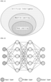
- FIG. 6 illustrates an example of a structure of a functional framework for radio access network (RAN) intelligence in a system applicable to the present disclosure.
- RAN radio access network
- Examples of input data may include measurements from UEs or different network entities, feedback from Actor, and output from an AI/ML model.
- Examples of input data may include measurements from UEs or different network entities, feedback from Actor, output from an AI/ML model.
- Model Training is a function that performs the ML model training, validation, and testing which may generate model performance metrics as part of the model testing procedure.
- the Model Training function is also responsible for data preparation (e.g., data pre-processing and cleaning, formatting, and transformation) based on Training Data delivered by a Data Collection function, if required.
- Model Deployment/Update Used to initially deploy a trained, validated, and tested AI/ML model to the Model Inference function or to deliver an updated model to the Model Inference function.
- Model Training is a function that performs the ML model training, validation, and testing which may generate model performance metrics as part of the model testing procedure.
- the Model Training function is also responsible for data preparation (e.g. data pre-processing and cleaning, formatting, and transformation) based on Training Data delivered by a Data Collection function, if required.
- Model Deployment/Update Used to initially deploy a trained, validated, and tested AI/ML model to the Model Inference function or to deliver an updated model to the Model Inference function.
- Model Inference is a function that provides AI/ML model inference output (e.g., predictions or decisions). Model Inference function may provide model performance feedback to Model Training function when applicable. The Model inference function is also responsible for data preparation (e.g., data pre-processing and cleaning, formatting, and transformation) based on Inference Data delivered by a Data Collection function, if required.
- data preparation e.g., data pre-processing and cleaning, formatting, and transformation
- (3-1) Output The inference output of the AI/ML model produced by a Model Inference function.
- Model Performance Feedback It may be used for monitoring the performance of the AI/ML model.
- Model Inference is a function that provides AI/ML model inference output (e.g. predictions or decisions). Model Inference function may provide model performance feedback to Model Training function when applicable. The Model inference function is also responsible for data preparation (e.g. data pre-processing and cleaning, formatting, and transformation) based on Inference Data delivered by a Data Collection function, if required.
- data preparation e.g. data pre-processing and cleaning, formatting, and transformation
- (3-1) Output The inference output of the AI/ML model produced by a Model Inference function.
- Model Performance Feedback It may be used for monitoring the performance of the AI/ML model.
- Actor is a function that receives the output from the Model inference function and triggers or performs corresponding actions.
- the Actor may trigger actions directed to other entities or to itself.
- the training data and the validation data within the entire training set are divided and used in a ratio of about 8:2 or 7:3, and if the test data is included, they is divided and used in a ratio of 6:2:2 (training: validation: test).
- a collaboration level can be defined as follows depending on whether the AI/ML function between a base station and a UE is capable, and variations due to combination or separation of levels below are also possible.
- Use cases to focus on: - Initial set of use cases includes: ⁇ CSI feedback enhancement, e.g., overhead reduction, improved accuracy, prediction [RAN1] ⁇ Beam management, e.g., beam prediction in time, and/or spatial domain for overhead and latency reduction, beam selection accuracy improvement [RAN1] ⁇ Positioning accuracy enhancements for different scenarios including, e.g., those with heavy NLOS conditions [RAN1] - Finalize representative sub use cases for each use case for characterization and baseline performance evaluations by RAN#98 ⁇
- the AI/ML approaches for the selected sub use cases need to be diverse enough to support various requirements on the gNB-UE collaboration levels Note: the selection of use cases for this study solely targets the formulation of a framework to apply AI/ML to the air-interface for these and other use cases.
- AI/ML model terminology and description to identify common and specific characteristics for framework investigations: - Characterize the defining stages of AI/ML related algorithms and associated complexity: ⁇ Model generation, e.g., model training (including input/output, pre-/post-process, online/offline as applicable), model validation, model testing, as applicable ⁇ Inference operation, e.g., input/output, pre-/post-process, as applicable - Identify various levels of collaboration between UE and gNB pertinent to the selected use cases, e.g., ⁇ No collaboration: implementation-based only AI/ML algorithms without information exchange [for comparison purposes] ⁇ Various levels of UE/gNB collaboration targeting at separate or joint ML operation.
- the present disclosure describes a method for a UE to report information capable of mainly using as an input parameter of BS AI/ML in AI/ML-based beam management and a beam reporting method through UE AI/ML.
- the present disclosure proposes a beam reporting operation of a UE for AI/ML-based beam management.
- a UE may perform best CRI/SSBRI(s) reporting from a best beam perspective with a large slope/derivative value and/or from a beam perspective with a slope/derivative value greater than or equal to a threshold, based on a slope of L1-RSRP/SINR values (e.g., based on a derivative value per time unit of L1-RSRP/SINR values) in CRIs/SSBRIs within CSI resource config for a specific beam reporting, in addition to/separately from legacy L1-RSRP/SINR-based beam reporting.
- L1-RSRP/SINR values e.g., based on a derivative value per time unit of L1-RSRP/SINR values
- the beam reporting for the slope/derivative value may be reported to the base station as an additional payload to a legacy beam reporting instance (e.g., CRI/SSBRI + RSRP/SINR value of the CRI/SSBRI + slope/derivative value of the CRI/SSBRI), or independently reported to the base station via a separate beam reporting configuration.
- a legacy beam reporting instance e.g., CRI/SSBRI + RSRP/SINR value of the CRI/SSBRI + slope/derivative value of the CRI/SSBRI
- a beam with a small absolute value of RSRP/SINR but a good slope may be selected and reported.
- the UE proposes a method of defining/configuring and using a metric that considers both an absolute value and a slope of L1-RSRP/SINR for a specific CRI/SSBRI (e.g., selecting a beam with a maximum value of w1*RSRP/SINR + w2*slope_RSRP/SINR). Or/and, the UE may select N1 beams based on the absolute value of RSRP/SINR and select N2 beams based on the slope to report a total of N1+N2 beam IDs and related quality information (RSRP/SINR value for N1 beams and slope/derivative value for N2 beams).
- a metric that considers both an absolute value and a slope of L1-RSRP/SINR for a specific CRI/SSBRI (e.g., selecting a beam with a maximum value of w1*RSRP/SINR + w2*slope_RSRP/SINR).
- reportQuantity for the beam reporting may be newly introduced.
- the slope/derivative value can be expressed as (y(t2) - y(t1)) / (t2 - t1) when the instantaneous L1-RSRP/SINR is expressed as a function with a time of y(x) as a variable.
- the time unit for calculating the slope/derivative value (in the above example, t1 and t2) or/and w1/w2 in the metric for considering both the absolute value and the slope may be specified/defined in the specification or configured/indicated by the base station configuration.
- the best beam reporting using the slope/derivative value may be used by the base station without any separate processing for the base station to determine the DL serving beam for the UE, or may be used as one of input parameters of an AI/ML function for future DL serving beam prediction at the base station side. That is, if the base station not having (or having) the AI/ML function configures and receives the UE beam reporting, the base station may immediately configure/indicate at least one of the reported best beams as a DL beam for DL transmission/reception because the beam reporting contains information that RSRP/SINR value of a specific beam increases.
- the base station when the base station having the AI/ML function drives the AI/ML function for the future DL serving beam prediction, the base station may apply the beam reporting information as one of the input parameters and use it for UE serving beam prediction. Afterwards, the base station may configure/indicate a DL beam for DL transmission/reception to the UE based on the predicted serving beam information.
- L3 filtered RSRP value may be used. That is, the UE may perform the best beam reporting on beams with a good tendency (e.g., slope/derivative value) of RSRP values filtered in L3.
- Layer 3 filtering in higher layer is performed by a procedure shown in table below. In the formula below, value of 'a' is configured by base station RRC configuration.
- the present invention proposes a method of performing L3 filtering for beam measurement quantity through base station AI/ML or/and UE AI/ML.
- the base station may configure an optimal value of 'a' to the UE through the AI/ML, or/and the UE may calculate and configure/apply a filter output (using the beam measurement(s) as the input parameter) for a specific beam measurement quantity through the AI/ML function, not performing L3 filtering using the formula below.
- M n is the latest received measurement result from the physical layer
- F n is the updated filtered measurement result, that is used for evaluation of reporting criteria or for measurement reporting
- F n-l is the old filtered measurement result, where F 0 is set to M 1 when the first measurement result from the physical layer is received
- a 1/2 ( ki /4)
- k i is the filterCoefficient for the corresponding measurement quantity of the i:th QuantityConfigNR in quantityConfigNR-List, and i is indicated by quantityConfigIndex in MeasObjectNR
- a 1/2 ( k /4)
- k is the filterCoefficient for the corresponding measurement quantity received by the quantityConfig, for UTRA-FDD
- a 1/2 (k/4)
- k is the filterCoefficient for the corresponding measurement quantity received by quantityConfigUTRA-FDD in the QuantityConfig, 3.
- a UE may perform best beam reporting for specific time instance(s) in the past or/and future time instance(s), in addition to/separately from legacy L1-RSRP/SINR-based beam reporting. That is, the UE device can report best CRI/SSBRI(s) and L1-RSRP/SINR values for each time stamp when reporting CRI/SSBRI and L1-RSRP/SINR values in a beam reporting payload.
- a beam reporting payload E.g., ...
- t-2 CRI1, -76 dBm, t-1: CRI1, -68 dBm, t: CRI3, -70 dBm, t+1: CRI3, -72 dBm, t+2: CRI3, -66 dBm, ....
- RSRP(/SINR) value of the best CRI/SSBRI of each time stamp may be represented by 7-bit value in the range [-140, -44](/[-23, 40]) dBm with 1(/0.5)dB step size
- RSRP(/SINR) value of the remaining CRIs/SSBRIs may be represented by computed with 2 dB(/1 dB) step size with a reference to the largest measured L1-RSRP(/SINR) value which is part of the same L1-RSRP(/SINR) reporting instance.
- the UE may report a change amount for the measurement/prediction value in the form of a function.
- f(a) may be a function of the change amount.
- the UE may report coefficients of the 0th, 1st, 2nd order ... (if needed) used to measure a change amount at a specific reference time (t0).
- the UE may report a change amount for the measurement/prediction value in the form of a function.
- f(a) may be a function of the change amount.
- the UE may report one or more coefficients of the 0th, 1st, 2nd order ... (if needed) used to measure a change amount at a specific reference time (t0). That is, the UE may report one or more coefficients within a polynomial to express the change amount/change rate.
- the time unit between the time stamps and the number of time stamps to be reported may be specified/defined in the specification or configured/indicated by the base station configuration.
- the best beam in the best beam report for instance(s) at a future point in time, the best beam may be determined based on the RSRP/SINR tendency measured at the UE as described in the proposal 1, or determined based on UE AI/ML calculation if there is an AI/ML function at the UE side.
- the best beam reporting for each time stamp in the proposal 2 may be used by the base station without any separate processing for the base station to determine the DL serving beam for the UE, or may be used as one of input parameters of an AI/ML function for future DL serving beam prediction at the base station side.
- At least one combination of embodiments of the proposals 1 and 2 can be used for the operation between the base station and the UE.
- An example of a UE (or base station) operation based on at least one of the above-described embodiments (e.g., at least one of the proposals 1 and 2) is as follows.
- the configuration information may be based on the proposals 1 and 2.
- the best beam measurement/determination may be based on the proposals 1 and 2.
- the UE/BS operation is merely an example, and each operation (and step) is not necessarily essential.
- operation related to beam measurement and reporting of the UE according to the above-described embodiments may be omitted or added based on a UE/BS implementation method.
- operations of the UE/BS can be processed by a device (e.g., processors 1610 and 1660 of FIG. 9 ) of FIG. 9 to be described below.
- a device e.g., processors 1610 and 1660 of FIG. 9
- the operations of the UE/BS can be stored in a memory (e.g., memories 1640 and 1690 of FIG. 9 ) in the form of commands/programs (e.g., instructions, executable codes) for running at least one processor (e.g., processors 1610 and 1660 of FIG. 9 ).
- a memory e.g., memories 1640 and 1690 of FIG. 9
- commands/programs e.g., instructions, executable codes
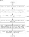
- FIG. 7 illustrates an example of an operation process of a UE in a system applicable to the present disclosure.
- a UE receives a channel state information (CSI) resource configuration from a base station.
- CSI channel state information
- step S3220 the UE receives a plurality of CSI-reference signals (RSs) from the base station based on a plurality of first CSI-reference signal resource indicators (CRIs) or a plurality of first synchronization signal block resource indicators (SSBRIs) related to the CSI resource configuration.
- RSs CSI-reference signals
- CRIs first CSI-reference signal resource indicators
- SSBRIs first synchronization signal block resource indicators
- step S3230 the UE measures a received signal received power (RSRP) or a signal to interference power (SINR) related to the first CRIs or the first SSBRIs.
- RSRP received signal received power
- SINR signal to interference power
- step S3240 the UE calculates a derivative value per time unit of the measured RSRP or SINR.
- step S3250 the UE selects a predetermined number of second CRIs or second SSBRIs from among the first CRIs or the first SSBRIs based on an absolute value and the derivative value of the RSRP or the SINR.
- step S3260 the UE transmits, to the base station, a report message related to the second CRIs or the second SSBRIs.
- the report message may include the absolute value of the RSRP or the SINR related to the second CRIs or the second SSBRIs and the derivative value of the RSRP or the SINR related to the second CRIs or the second SSBRIs.
- the report message may include a first report configuration based on the absolute value of the RSRP or the SINR related to the second CRIs or the second SSBRIs and a second report configuration based on the derivative value of the RSRP or the SINR related to the second CRIs or the second SSBRIs.
- the second report configuration may be transmitted together with the first report configuration as an additional payload of the first report configuration.
- the second report configuration may be configured separately from the first report configuration and transmitted separately from the first report configuration.
- the second CRIs or the second SSBRIs may include (N1+N2) CRIs or (N1+N2) SSBRIs.
- N1 CRIs or N1 SSBRIs among the second CRIs or the second SSBRIs may be CRIs or SSBRIs determined based on the absolute value of the RSRP or the SINR among the plurality of first CRIs or first SSBRIs.
- N2 CRIs or N2 SSBRIs among the second CRIs or the second SSBRIs may be CRIs or SSBRIs determined based on the derivative value of the RSRP or the SINR among the plurality of first CRIs or first SSBRIs.
- the report message may be based on a metric based on both the absolute value and the derivative value of the RSRP or the SINR.
- the second CRIs or the second SSBRIs may be a predetermined number of CRIs or SSBRIs with a highest value based on the metric among the first CRIs or the first SSBRIs.
- the report message may include an optimal second CRI or second SSBRI for each time stamp, and the RSRP or the SINR related to the optimal second CRI or second SSBRI per time.
- the report message may include a report on an optimal CRI or SSBRI for a specific time in the past or future based on the second CRIs or the second SSBRIs or a prediction of the optimal CRI or SSBRI.
- the report message may be expressed in the form of a rate of change value at a specific time for one or more of the absolute value of the RSRP or the SINR related to the second CRIs or the second SSBRIs or the derivative of the RSRP or the SINR related to the second CRIs or the second SSBRIs.
- the report message may include information on CRIs or SSBRIs with a best change rate based on the rate of change value.
- the rate of change value at the specific time may be calculated by a polynomial based on a variable at the specific time.
- the report message may include information on one or more coefficients included in the polynomial.
- a user equipment in a wireless communication system.
- the UE may include a transceiver and at least one processor, and the at least one processor may be configured to perform the operation method of the UE based on FIG. 7 .
- a device controlling a user equipment (UE) in a wireless communication system may include at least one processor and at least one memory operably connected to the at least one processor.
- the at least one memory may be configured to store instructions performing the operation method of the UE based on FIG. 7 based on being executed by the at least one processor.
- one or more non-transitory computer readable mediums storing one or more instructions.
- the one or more instructions may be configured to perform operations based on being executed by one or more processors, and the operations may include the operation method of the UE based on FIG. 7 .
- FIG. 8 illustrates an example of an operation process of a base station in a system applicable to the present disclosure.
- the base station transmits a plurality of CSI-reference signals (RSs) to the UE based on a plurality of first CSI-reference signal resource indicators (CRIs) or a plurality of first synchronization signal block resource indicators (SSBRIs) related to the CSI resource configuration.
- RSs CSI-reference signals
- CRIs first CSI-reference signal resource indicators
- SSBRIs first synchronization signal block resource indicators
- step S3330 the base station receives, from the UE, a report message related to second CRIs or second SSBRIs which are a part of the first CRIs or the first SSBRIs.
- the second CRIs or the second SSBRIs may be a predetermined number of CRIs or SSBRIs selected based on an absolute value of a received signal received power (RSRP) or a signal to interference power (SINR) related to the first CRIs or the first SSBRIs and a derivative value per time unit of the RSRP or the SINR related to the first CRIs or the first SSBRIs from among the first CRIs or the first SSBRIs.
- RSRP received signal received power
- SINR signal to interference power
- the report message may include a first report configuration based on the absolute value of the RSRP or the SINR related to the second CRIs or the second SSBRIs and a second report configuration based on the derivative value of the RSRP or the SINR related to the second CRIs or the second SSBRIs.
- the second report configuration may be received together with the first report configuration as an additional payload of the first report configuration.
- the second report configuration may be configured separately from the first report configuration and received separately from the first report configuration.
- the second CRIs or the second SSBRIs may include (N1+N2) CRIs or (N1+N2) SSBRIs.
- N1 CRIs or N1 SSBRIs among the second CRIs or the second SSBRIs may be CRIs or SSBRIs determined based on the absolute value of the RSRP or the SINR among the plurality of first CRIs or first SSBRIs.
- N2 CRIs or N2 SSBRIs among the second CRIs or the second SSBRIs may be CRIs or SSBRIs determined based on the derivative value of the RSRP or the SINR among the plurality of first CRIs or first SSBRIs.
- the report message may be based on a metric based on both the absolute value and the derivative value of the RSRP or the SINR.
- the second CRIs or the second SSBRIs may be a predetermined number of CRIs or SSBRIs with a highest value based on the metric among the first CRIs or the first SSBRIs.
- the report message may include an optimal second CRI or second SSBRI for each time stamp, and the RSRP or the SINR related to the optimal second CRI or second SSBRI per time.
- the report message may include a report on an optimal CRI or SSBRI for a specific time in the past or future based on the second CRIs or the second SSBRIs or a prediction of the optimal CRI or SSBRI.
- the report message may be expressed in the form of a rate of change value at a specific time for one or more of the absolute value of the RSRP or the SINR related to the second CRIs or the second SSBRIs or the derivative of the RSRP or the SINR related to the second CRIs or the second SSBRIs.
- the report message may include information on CRIs or SSBRIs with a best change rate based on the rate of change value.
- the rate of change value at the specific time may be calculated by a polynomial based on a variable at the specific time.
- the report message may include information on one or more coefficients included in the polynomial.
- a base station in a wireless communication system may include a transceiver and at least one processor, and the at least one processor may be configured to perform the operation method of the BS based on FIG. 8 .
- a device controlling a base station in a wireless communication system may include at least one processor and at least one memory operably connected to the at least one processor.
- the at least one memory may be configured to store instructions performing the operation method of the BS based on FIG. 8 based on being executed by the at least one processor.
- one or more non-transitory computer readable mediums storing one or more instructions.
- the one or more instructions may be configured to perform operations based on being executed by one or more processors, and the operations may include the operation method of the BS based on FIG. 8 .
- FIG. 9 illustrates an example of a structure of a first device and a second device in a system applicable to the present disclosure.
- a first device 1600 may include a processor 1610, an antenna unit 1620, a transceiver 1630, and a memory 1640.
- the processor 1610 may perform baseband-related signal processing and include a higher layer processing unit 1611 and a physical layer processing unit 1615.
- the higher layer processing unit 1611 may process operations of the MAC layer, the RRC layer, or higher layers.
- the physical layer processing unit 1615 may process the operation of the PHY layer. For example, if the first device 1600 is a base station (BS) device in BS-UE communication, the physical layer processing unit 1615 may perform uplink reception signal processing, downlink transmission signal processing, and the like. For example, if the first device 1600 is a first UE device in inter-UE communication, the physical layer processing unit 1615 may performs downlink reception signal processing, uplink transmission signal processing, sidelink transmission signal processing, and the like.
- the processor 1610 may control the overall operation of the first device 1600 in addition to performing the baseband-related signal processing.
- the antenna unit 1620 may include one or more physical antennas and support MIMO transmission/reception if the antenna unit 1620 includes a plurality of antennas.
- the transceiver 1630 may include a radio frequency (RF) transmitter and an RF receiver.
- the memory 1640 may store information processed by the processor 1610 and software, operating systems, and applications related to the operation of the first device 1600.
- the memory 1640 may also include components such as a buffer.
- the processor 1610 of the first device 1600 may be configured to implement the operation of the BS in the BS-UE communication (or the operation of the first UE device in the inter-UE communication) in embodiments described in the present disclosure.
- the second device 1650 may include a processor 1660, an antenna unit 1670, a transceiver 1680, and a memory 1690.
- the processor 1660 may perform baseband-related signal processing and include a higher layer processing unit 1661 and a physical layer processing unit 1665.
- the higher layer processing unit 1661 may process the operation of the MAC layer, the RRC layer, or higher layers.
- the physical layer processing unit 1665 may process the operation of the PHY layer. For example, if the second device 1650 is a UE device in BS-UE communication, the physical layer processing unit 1665 may perform downlink reception signal processing, uplink transmission signal processing, and the like. For example, if the second device 1650 is a second UE device in inter-UE communication, the physical layer processing unit 1665 may perform downlink reception signal processing, uplink transmission signal processing, sidelink reception signal processing, and the like.
- the processor 1660 may control the overall operation of the second device 1660 in addition to performing the baseband-related signal processing.
- the antenna unit 1670 may include one or more physical antennas and support MIMO transmission/reception if the antenna unit 1670 includes a plurality of antennas.
- the transceiver 1680 may include an RF transmitter and an RF receiver.
- the memory 1690 may store information processed by the processor 1660 and software, operating systems, and applications related to the operation of the second device 1650.
- the memory 1690 may also include components such as a buffer.
- the processor 1660 of the second device 1650 may be configured to implement the operation of the UE in the BS-UE communication (or the operation of the second UE device in the inter-UE communication) in embodiments described in the present disclosure.
- the wireless communication technology implemented in the devices 1600 and 1650 according to the present disclosure may further include narrowband Internet of Things (NB-IoT) for low-power communication in addition to LTE, NR, and 6G.
- NB-IoT narrowband Internet of Things
- the NB-IoT technology may be an example of a low power wide area network (LPWAN) technology and may be implemented in standards such as LTE Cat NB1 and/or LTE Cat NB2.
- LPWAN low power wide area network
- LTE Cat NB1 low power wide area network
- LTE Cat NB2 LTE Cat NB2
- the NB-IoT technology is not limited to the above-described names.
- the wireless communication technology implemented in the devices 1600 and 1650 according to the present disclosure may perform communication based on LTE-M technology.
- the LTE-M technology may be an example of the LPWAN technology, and may be called by various names such as enhanced machine type communication (eMTC).
- eMTC enhanced machine type communication
- the LTE-M technology may be implemented with at least one of various standards such as 1) LTE CAT 0, 2) LTE Cat M1, 3) LTE Cat M2, 4) LTE non-BL (non-Bandwidth Limited), 5) LTE-MTC, 6) LTE machine type communication, and/or 7) LTE M.
- the LTE-M technology is not limited to the above-mentioned names.
- the wireless communication technology implemented in the devices 1600 and 1650 according to the present disclosure may include at least one of ZigBee, Bluetooth, and low power wide area network (LPWAN) in consideration of low power communication, and is not limited to the above-mentioned names.
- the ZigBee technology may create personal area networks (PAN) related to small/low-power digital communication based on various standards such as IEEE 802.15.4, and may be called by various names.
Landscapes
- Engineering & Computer Science (AREA)
- Signal Processing (AREA)
- Theoretical Computer Science (AREA)
- Physics & Mathematics (AREA)
- Computer Networks & Wireless Communication (AREA)
- Software Systems (AREA)
- Artificial Intelligence (AREA)
- General Engineering & Computer Science (AREA)
- Data Mining & Analysis (AREA)
- Evolutionary Computation (AREA)
- Mathematical Physics (AREA)
- General Physics & Mathematics (AREA)
- Computing Systems (AREA)
- Biomedical Technology (AREA)
- Molecular Biology (AREA)
- General Health & Medical Sciences (AREA)
- Computational Linguistics (AREA)
- Biophysics (AREA)
- Life Sciences & Earth Sciences (AREA)
- Health & Medical Sciences (AREA)
- Computer Vision & Pattern Recognition (AREA)
- Medical Informatics (AREA)
- Mobile Radio Communication Systems (AREA)
Applications Claiming Priority (2)
| Application Number | Priority Date | Filing Date | Title |
|---|---|---|---|
| KR20220053047 | 2022-04-28 | ||
| PCT/KR2023/005695 WO2023211152A1 (ko) | 2022-04-28 | 2023-04-26 | 무선 통신 시스템에서 ai/ml 기반 빔 관리를 수행하기 위한 장치 및 방법 |
Publications (1)
| Publication Number | Publication Date |
|---|---|
| EP4518178A1 true EP4518178A1 (de) | 2025-03-05 |
Family
ID=88519123
Family Applications (1)
| Application Number | Title | Priority Date | Filing Date |
|---|---|---|---|
| EP23796795.5A Pending EP4518178A1 (de) | 2022-04-28 | 2023-04-26 | Vorrichtung und verfahren zur durchführung von ai/ml-basierter strahlverwaltung in einem drahtloskommunikationssystem |
Country Status (3)
| Country | Link |
|---|---|
| EP (1) | EP4518178A1 (de) |
| CN (1) | CN119547345A (de) |
| WO (1) | WO2023211152A1 (de) |
Families Citing this family (2)
| Publication number | Priority date | Publication date | Assignee | Title |
|---|---|---|---|---|
| KR20250097480A (ko) * | 2023-12-21 | 2025-06-30 | 삼성전자주식회사 | 무선 통신 시스템에서 링크 적응을 위한 ai 기반 채널 정보를 보고하는 방법 및 장치와 이를 이용한 링크 적응 방법 및 장치 |
| CN120602970A (zh) * | 2024-03-05 | 2025-09-05 | 维沃移动通信有限公司 | 测量处理方法、测量配置方法、装置、设备及可读存储介质 |
Family Cites Families (5)
| Publication number | Priority date | Publication date | Assignee | Title |
|---|---|---|---|---|
| US10863433B2 (en) * | 2018-02-13 | 2020-12-08 | Mediatek Inc. | Power saving on UE reports |
| KR102633678B1 (ko) * | 2019-01-25 | 2024-02-02 | 지티이 코포레이션 | 무선 통신에서의 채널 상태 추정 및 보고 방식 |
| WO2020215106A2 (en) * | 2019-11-07 | 2020-10-22 | Futurewei Technologies, Inc. | Methods and apparatus for information feedback |
| US12200641B2 (en) * | 2020-09-22 | 2025-01-14 | Samsung Electronics Co., Ltd. | Method and apparatus for beam measurement, reporting and indication |
| EP4218155A1 (de) * | 2020-09-30 | 2023-08-02 | Nokia Technologies Oy | Frühe ue-tafelschaltmeldung |
-
2023
- 2023-04-26 EP EP23796795.5A patent/EP4518178A1/de active Pending
- 2023-04-26 WO PCT/KR2023/005695 patent/WO2023211152A1/ko not_active Ceased
- 2023-04-26 CN CN202380035779.8A patent/CN119547345A/zh active Pending
Also Published As
| Publication number | Publication date |
|---|---|
| CN119547345A (zh) | 2025-02-28 |
| WO2023211152A1 (ko) | 2023-11-02 |
Similar Documents
| Publication | Publication Date | Title |
|---|---|---|
| US20240298202A1 (en) | Method and device for transmitting or receiving channel state information in wireless communication system | |
| EP4373002A1 (de) | Verfahren und vorrichtung zum senden oder empfangen von strahlinformationen in einem drahtloskommunikationssystem | |
| EP4422107A1 (de) | Verfahren und vorrichtung zum senden/empfangen eines drahtlossignals in einem drahtloskommunikationssystem | |
| EP4518412A1 (de) | Verfahren und vorrichtung zum senden und empfangen von kanalstatusinformationen in einem drahtloskommunikationssystem | |
| US20250192963A1 (en) | Method and device for transmitting or receiving improved codebook-based channel state information in wireless communication system | |
| US20250096966A1 (en) | Method and device for transmitting and receiving physical channel in wireless communication system | |
| US20240396608A1 (en) | Method and device for transmitting/receiving wireless signal in wireless communication system | |
| EP4518178A1 (de) | Vorrichtung und verfahren zur durchführung von ai/ml-basierter strahlverwaltung in einem drahtloskommunikationssystem | |
| EP4465705A1 (de) | Verfahren und vorrichtung zum senden/empfangen eines drahtlossignals in einem drahtloskommunikationssystem | |
| US20250159523A1 (en) | Method and device for transmitting or receiving quantization-based channel state information in wireless communication system | |
| EP4557624A1 (de) | Verfahren und vorrichtung zur strahlmeldung in einem drahtloskommunikationssystem | |
| US20250008347A1 (en) | Method and apparatus for performing uplink or downlink transmission/reception in wireless communication system | |
| US20250226946A1 (en) | Training dataset obtaining method and apparatus | |
| EP4597867A1 (de) | Verfahren und vorrichtung zum senden oder empfangen von kanalstatusinformationen in einem drahtloskommunikationssystem | |
| EP4654639A1 (de) | Verfahren und vorrichtung zum senden oder empfangen von kapazitätsinformationen in einem drahtloskommunikationssystem | |
| US20250247180A1 (en) | Method and device for transmitting/receiving wireless signal in wireless communication system | |
| US20250323768A1 (en) | Method and device for transmitting and receiving signal in wireless communication system | |
| CN120077578A (zh) | 无线通信系统中用于波束指示的方法和装置 | |
| EP4542875A1 (de) | Verfahren und vorrichtung zum senden/empfangen von kanalstatusinformationen in einem drahtloskommunikationssystem | |
| US20260039367A1 (en) | Method and device for beam management in wireless communication system | |
| EP4694428A1 (de) | Verfahren und vorrichtung zum senden/empfangen eines signals in einem drahtloskommunikationssystem | |
| EP4614828A1 (de) | Verfahren und vorrichtung zur strahlanzeige in einem drahtloskommunikationssystem | |
| EP4518177A1 (de) | Verfahren und vorrichtung für uplink-übertragung und -empfang in einem drahtloskommunikationssystem | |
| US20260122627A1 (en) | Method and device for beam indication in wireless communication system | |
| EP4661304A1 (de) | Verfahren und vorrichtung zum senden und empfangen von kanalstatusinformationen in einem drahtloskommunikationssystem |
Legal Events
| Date | Code | Title | Description |
|---|---|---|---|
| STAA | Information on the status of an ep patent application or granted ep patent |
Free format text: STATUS: THE INTERNATIONAL PUBLICATION HAS BEEN MADE |
|
| PUAI | Public reference made under article 153(3) epc to a published international application that has entered the european phase |
Free format text: ORIGINAL CODE: 0009012 |
|
| STAA | Information on the status of an ep patent application or granted ep patent |
Free format text: STATUS: REQUEST FOR EXAMINATION WAS MADE |
|
| 17P | Request for examination filed |
Effective date: 20241126 |
|
| AK | Designated contracting states |
Kind code of ref document: A1 Designated state(s): AL AT BE BG CH CY CZ DE DK EE ES FI FR GB GR HR HU IE IS IT LI LT LU LV MC ME MK MT NL NO PL PT RO RS SE SI SK SM TR |
|
| DAV | Request for validation of the european patent (deleted) | ||
| DAX | Request for extension of the european patent (deleted) |