EP4518102A1 - Interior permanent magnet rotor and rotating electric machine - Google Patents
Interior permanent magnet rotor and rotating electric machine Download PDFInfo
- Publication number
- EP4518102A1 EP4518102A1 EP22930173.4A EP22930173A EP4518102A1 EP 4518102 A1 EP4518102 A1 EP 4518102A1 EP 22930173 A EP22930173 A EP 22930173A EP 4518102 A1 EP4518102 A1 EP 4518102A1
- Authority
- EP
- European Patent Office
- Prior art keywords
- permanent magnet
- rotor
- rotor core
- magnet housing
- interior
- Prior art date
- Legal status (The legal status is an assumption and is not a legal conclusion. Google has not performed a legal analysis and makes no representation as to the accuracy of the status listed.)
- Withdrawn
Links
Images


Classifications
-
- H—ELECTRICITY
- H02—GENERATION; CONVERSION OR DISTRIBUTION OF ELECTRIC POWER
- H02K—DYNAMO-ELECTRIC MACHINES
- H02K1/00—Details of the magnetic circuit
- H02K1/06—Details of the magnetic circuit characterised by the shape, form or construction
- H02K1/22—Rotating parts of the magnetic circuit
- H02K1/27—Rotor cores with permanent magnets
- H02K1/2706—Inner rotors
- H02K1/272—Inner rotors the magnetisation axis of the magnets being perpendicular to the rotor axis
- H02K1/274—Inner rotors the magnetisation axis of the magnets being perpendicular to the rotor axis the rotor consisting of two or more circumferentially positioned magnets
- H02K1/2753—Inner rotors the magnetisation axis of the magnets being perpendicular to the rotor axis the rotor consisting of two or more circumferentially positioned magnets the rotor consisting of magnets or groups of magnets arranged with alternating polarity
- H02K1/276—Magnets embedded in the magnetic core, e.g. interior permanent magnets [IPM]
-
- H—ELECTRICITY
- H02—GENERATION; CONVERSION OR DISTRIBUTION OF ELECTRIC POWER
- H02K—DYNAMO-ELECTRIC MACHINES
- H02K1/00—Details of the magnetic circuit
- H02K1/06—Details of the magnetic circuit characterised by the shape, form or construction
- H02K1/22—Rotating parts of the magnetic circuit
- H02K1/28—Means for mounting or fastening rotating magnetic parts on to, or to, the rotor structures
Definitions
- the present invention relates to an interior magnet rotor and a rotary electric machine.
- through-holes extending in an axial direction are formed in regions near a radially outer side in the rotor core to house permanent magnets.
- this through-hole has not only a space to house the permanent magnet but also partial spaces at a radially outer side and inner side. These partial spaces are flux barriers that suppress passage of magnetic fluxes.
- top bridges which are part of the rotor core, are present between the radially outer partial space and an outer surface of the rotor core to strengthen a structure of the rotor core.
- the top bridges serve as paths of magnetic fluxes caused by the permanent magnet, that is, magnetic paths.
- the magnetic fluxes that pass through the magnetic paths become leakage fluxes that stay only inside the rotor and are not interlinked with stator side, leading to low torque efficiency of the rotary electric machine.
- Patent Document 1 Japanese Patent Application Laid-open No. 2020-182358
- An object of the present invention is to provide a rotary electric machine that enables prevention of excessive bending stress on the center bridges in an interior magnet rotor without top bridges.
- an interior magnet rotor comprises: a rotor shaft extending in an axial direction; a rotor core attached to a radially outer side of the rotor shaft, and having two permanent magnet housing holes that are formed in a radially outer portion of the rotor core, disposed with circumferential intervals therebetween, and arranged across each d-axis; and plate-shaped permanent magnets respectively housed in the permanent magnet housing holes, wherein the permanent magnet housing hole is communicated with an outside of an outer peripheral surface of the rotor core, the permanent magnet housing hole has gaps between the permanent magnet and a housing portion that houses the permanent magnet, and the gaps are filled with a filler.
- FIG. 1 is a cross-sectional view illustrating a configuration of a rotary electric machine 200 according to a first embodiment.
- the rotary electric machine 200 includes: an interior magnet rotor 100 having a rotor shaft 110 extending in a rotation-axis direction (axial direction), a rotor core 120 attached to the rotor shaft 110, and a plurality of permanent magnets 130; a stator 10; and two bearings (not illustrated) by which the rotor shaft 110 is rotatably supported.
- a plurality of permanent magnet housing holes 121 are formed in the rotor core 120.
- two permanent magnet housing holes 121 are formed across each d-axis and center bridge 125, in a V-shaped arrangement projecting radially inward.
- FIG. 1 illustrates only one of eight d axes. Note that though FIG. 1 illustrates the case where there is only one layer of the V-shaped arrangement as an example, this is not restrictive.
- the V-shaped arrangement may be formed in a plurality of layers in a radial direction.
- the permanent magnet 130 is plate-shaped. Though FIG. 1 illustrates the case where the permanent magnet 130 is flat plate-shaped as an example, the permanent magnet 130 may have, for example, a curved shape in its cross-section perpendicular to the rotation axis of the rotor shaft 110 (vertical cross-section).
- the stator 10 has a cylindrical stator core 11, which is disposed to surround the rotor core 120 on a radially outer side of the rotor core 120 with a gap 15 therebetween and formed with stator teeth 11a.
- a plurality of stator teeth 11a are formed on an inner peripheral side of the stator 10, and disposed with circumferential intervals therebetween, for winding a non-illustrated stator winding.
- FIG. 2 is a partial cross-sectional view illustrating a configuration of an inter-pole portion of the interior magnet rotor 100 according to the first embodiment.
- FIG. 2 illustrates a portion around one d-axis.
- the two permanent magnet housing holes 121 are formed in the V-shaped arrangement projecting radially inward across the center bridge 125.
- Each permanent magnet housing hole 121 has a holding space formed by an outer wall 121a and an inner wall 121b to hold the permanent magnet 130, an outer space 121c adjacent to the radially outer side of the holding space, and an inner space 121d adjacent to the radially inner side of the holding space.
- the outer space 121c is communicated with the gap 15 through an opening 126 formed on an outer peripheral surface of the rotor core 120.
- a fan-shaped portion 128 is formed in the rotor core 120, sandwiched between the two permanent magnet housing holes 121, with the center bridge 125 as a keystone of the fan.
- a distance between the outer wall 121a and inner wall 121b of each permanent magnet housing hole 121 is formed to be larger than a thickness of the permanent magnet 130. Therefore, an outer gap 121f and inner gap 121g are formed between the outer wall 121a and the permanent magnet 130, and between the inner wall 121b and the permanent magnet 130, respectively.
- the outer gap 121f and inner gap 121g are filled with a filler to form a filling portion 141 and filling portion 142, respectively.
- the filler is, for example, a molding material such as a polymer compound or an adhesive.
- a total width of each of the outer gap 121f and inner gap 121g is constant, but the percentage of each is not limited.
- One of the gaps may be from 0% to 100% of the other, that is, the gap may be biased one way or the other.
- FIG. 3 is a partial cross-sectional view illustrating a configuration of an inter-pole portion of a modification example of the interior magnet rotor 100 according to the first embodiment.
- the outer space 121c and inner space 121d are also filled with the filler to form a filling portion 143 and filling portion 144, respectively.
- FIG. 4 is a partial cross-sectional view illustrating a configuration of an inter-pole portion for explaining the effect of the interior magnet rotor 100 according to the first embodiment. Common parts with the embodiment will be denoted by the same reference signs, for convenience of explanation.
- FIG. 4 illustrates a conventional case in which, unlike the present embodiment and modification example, the filling portion is not formed in the permanent magnet housing hole 121.
- the gaps corresponding to the outer gap 121f and inner gap 121g as in this embodiment are not formed by intended way, but there is a gap, which is necessary to insert the permanent magnet 130 into the permanent magnet housing hole 121.
- the fan-shaped portion 128 and adjacent portions of the rotor core 120 are mechanically integrated with each other at least through the filling portions 141 and 142.
- the load added to the fan-shaped portion 128 is transferred to the adjacent portions of the rotor core 120, and no bending stress on the center bridge 125 is generated.
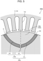
- FIG. 5 is a partial cross-sectional view illustrating a configuration of an inter-pole portion of an interior magnet rotor 100a according to a second embodiment.
- the present embodiment is a modification of the first embodiment.
- the interior magnet rotor 100a of a rotary electric machine 200a in this embodiment has permanent magnets 131 instead of the permanent magnets 130 in the first embodiment.
- the permanent magnet 131 is a bond magnet.
- the permanent magnet 131 is formed by filling a permanent magnet housing hole 122 with the bond magnet. Therefore, no gap is formed between the permanent magnet 131 and the permanent magnet housing hole 122, unlike the first embodiment.
- the fan-shaped portion 128 and the adjacent portions of the rotor core 120 are mechanically integrated with each other through the permanent magnets 131. As a result, the load added to the fan-shaped portion 128 is transferred to the adjacent portions of the rotor core 120, and no bending stress on the center bridge 125 is generated.
Landscapes
- Engineering & Computer Science (AREA)
- Power Engineering (AREA)
- Permanent Field Magnets Of Synchronous Machinery (AREA)
- Iron Core Of Rotating Electric Machines (AREA)
Abstract
Description
- The present invention relates to an interior magnet rotor and a rotary electric machine.
- In the rotary electric machine having the interior magnet rotor, through-holes extending in an axial direction are formed in regions near a radially outer side in the rotor core to house permanent magnets. Typically, this through-hole has not only a space to house the permanent magnet but also partial spaces at a radially outer side and inner side. These partial spaces are flux barriers that suppress passage of magnetic fluxes.
- In many cases, top bridges, which are part of the rotor core, are present between the radially outer partial space and an outer surface of the rotor core to strengthen a structure of the rotor core.
- The top bridges serve as paths of magnetic fluxes caused by the permanent magnet, that is, magnetic paths. The magnetic fluxes that pass through the magnetic paths become leakage fluxes that stay only inside the rotor and are not interlinked with stator side, leading to low torque efficiency of the rotary electric machine.
- On this background, there are cases of rotors using a method that removes the top bridges and connects the above-mentioned radially outer flux barriers to a space outside the rotor core (a gap space between the rotor and stator).
- Patent Document 1:
Japanese Patent Application Laid-open No. 2020-182358 - In an interior magnet rotor without top bridges, while leakage fluxes can be reduced as described above, excessive bending stress is generated in center bridges on a radially inner side when a circumferential load is applied to the magnet and the rotor core on an outer peripheral side of the magnet due to the rotor torque. Therefore, it is necessary to make the center bridges thicker, but this increases leakage fluxes and reduces torque performance.
- An object of the present invention is to provide a rotary electric machine that enables prevention of excessive bending stress on the center bridges in an interior magnet rotor without top bridges.
- To achieve the above object, an interior magnet rotor according to an embodiment of the present invention comprises: a rotor shaft extending in an axial direction; a rotor core attached to a radially outer side of the rotor shaft, and having two permanent magnet housing holes that are formed in a radially outer portion of the rotor core, disposed with circumferential intervals therebetween, and arranged across each d-axis; and plate-shaped permanent magnets respectively housed in the permanent magnet housing holes, wherein the permanent magnet housing hole is communicated with an outside of an outer peripheral surface of the rotor core, the permanent magnet housing hole has gaps between the permanent magnet and a housing portion that houses the permanent magnet, and the gaps are filled with a filler.
-
-
FIG. 1 is a cross-sectional view illustrating a configuration of a rotary electric machine according to a first embodiment. -
FIG. 2 is a partial cross-sectional view illustrating a configuration of an inter-pole portion of an interior magnet rotor according to the first embodiment. -
FIG. 3 is a partial cross-sectional view illustrating a configuration of an inter-pole portion of a modification example of the interior magnet rotor according to the first embodiment. -
FIG. 4 is a partial cross-sectional view illustrating a configuration of an inter-pole portion for explaining an effect of the interior magnet rotor according to the first embodiment. -
FIG. 5 is a partial cross-sectional view illustrating a configuration of an inter-pole portion of an interior magnet rotor according to a second embodiment. - An interior magnet rotor and a rotary electric machine according to embodiments of the present invention will be described below with reference to the drawings. Identical or similar parts will be denoted by common reference signs and a redundant description thereof will be omitted here.
-
FIG. 1 is a cross-sectional view illustrating a configuration of a rotaryelectric machine 200 according to a first embodiment. - The rotary
electric machine 200 includes: aninterior magnet rotor 100 having arotor shaft 110 extending in a rotation-axis direction (axial direction), arotor core 120 attached to therotor shaft 110, and a plurality ofpermanent magnets 130; astator 10; and two bearings (not illustrated) by which therotor shaft 110 is rotatably supported. - A plurality of permanent
magnet housing holes 121 are formed in therotor core 120. In detail, two permanentmagnet housing holes 121 are formed across each d-axis andcenter bridge 125, in a V-shaped arrangement projecting radially inward.FIG. 1 illustrates only one of eight d axes. Note that thoughFIG. 1 illustrates the case where there is only one layer of the V-shaped arrangement as an example, this is not restrictive. The V-shaped arrangement may be formed in a plurality of layers in a radial direction. - The
permanent magnet 130 is plate-shaped. ThoughFIG. 1 illustrates the case where thepermanent magnet 130 is flat plate-shaped as an example, thepermanent magnet 130 may have, for example, a curved shape in its cross-section perpendicular to the rotation axis of the rotor shaft 110 (vertical cross-section). - The
stator 10 has acylindrical stator core 11, which is disposed to surround therotor core 120 on a radially outer side of therotor core 120 with agap 15 therebetween and formed withstator teeth 11a. A plurality ofstator teeth 11a are formed on an inner peripheral side of thestator 10, and disposed with circumferential intervals therebetween, for winding a non-illustrated stator winding. -
FIG. 2 is a partial cross-sectional view illustrating a configuration of an inter-pole portion of theinterior magnet rotor 100 according to the first embodiment.FIG. 2 illustrates a portion around one d-axis. - As mentioned above, with respect to the d-axis, the two permanent
magnet housing holes 121 are formed in the V-shaped arrangement projecting radially inward across thecenter bridge 125. - Each permanent
magnet housing hole 121 has a holding space formed by anouter wall 121a and aninner wall 121b to hold thepermanent magnet 130, anouter space 121c adjacent to the radially outer side of the holding space, and aninner space 121d adjacent to the radially inner side of the holding space. - The
outer space 121c is communicated with thegap 15 through an opening 126 formed on an outer peripheral surface of therotor core 120. As a result, a fan-shaped portion 128 is formed in therotor core 120, sandwiched between the two permanentmagnet housing holes 121, with thecenter bridge 125 as a keystone of the fan. - A distance between the
outer wall 121a andinner wall 121b of each permanentmagnet housing hole 121 is formed to be larger than a thickness of thepermanent magnet 130. Therefore, anouter gap 121f andinner gap 121g are formed between theouter wall 121a and thepermanent magnet 130, and between theinner wall 121b and thepermanent magnet 130, respectively. - The
outer gap 121f andinner gap 121g are filled with a filler to form afilling portion 141 and fillingportion 142, respectively. Here, the filler is, for example, a molding material such as a polymer compound or an adhesive. - A total width of each of the
outer gap 121f andinner gap 121g is constant, but the percentage of each is not limited. One of the gaps may be from 0% to 100% of the other, that is, the gap may be biased one way or the other. -
FIG. 3 is a partial cross-sectional view illustrating a configuration of an inter-pole portion of a modification example of theinterior magnet rotor 100 according to the first embodiment. - In this modification example, in addition to the example illustrated in
FIG. 2 , theouter space 121c andinner space 121d are also filled with the filler to form afilling portion 143 and fillingportion 144, respectively. - Next, operations and effects of this embodiment and modification example will be explained.
-
FIG. 4 is a partial cross-sectional view illustrating a configuration of an inter-pole portion for explaining the effect of theinterior magnet rotor 100 according to the first embodiment. Common parts with the embodiment will be denoted by the same reference signs, for convenience of explanation. -
FIG. 4 illustrates a conventional case in which, unlike the present embodiment and modification example, the filling portion is not formed in the permanentmagnet housing hole 121. In the conventional case, the gaps corresponding to theouter gap 121f andinner gap 121g as in this embodiment are not formed by intended way, but there is a gap, which is necessary to insert thepermanent magnet 130 into the permanentmagnet housing hole 121. - During rotation of the
interior magnet rotor 100, a circumferential load is applied to thepermanent magnets 130 and the fan-shaped portion 128 due to the torque. In particular, an excessive load is added during acceleration or deceleration. This circumferential load causes excessive bending stress on thecenter bridge 125. - On the other hand, in the present embodiment and modification example, the fan-
shaped portion 128 and adjacent portions of therotor core 120 are mechanically integrated with each other at least through thefilling portions shaped portion 128 is transferred to the adjacent portions of therotor core 120, and no bending stress on thecenter bridge 125 is generated. - Therefore, there is no need to take a measure to increase the width of the
center bridge 125 to ensure rigidity of thecenter bridge 125, which would result in increased leakage flux. -
FIG. 5 is a partial cross-sectional view illustrating a configuration of an inter-pole portion of aninterior magnet rotor 100a according to a second embodiment. - The present embodiment is a modification of the first embodiment. The
interior magnet rotor 100a of a rotaryelectric machine 200a in this embodiment haspermanent magnets 131 instead of thepermanent magnets 130 in the first embodiment. - Here, the
permanent magnet 131 is a bond magnet. Thepermanent magnet 131 is formed by filling a permanentmagnet housing hole 122 with the bond magnet. Therefore, no gap is formed between thepermanent magnet 131 and the permanentmagnet housing hole 122, unlike the first embodiment. - In
FIG. 5 , thepermanent magnet 131 is not flat plate-shaped but aspect-shaped in the width direction, but the shape is not restrictive. For example, the permanentmagnet housing hole 122 may be formed to house a flat plate-shaped permanent magnet. - In this embodiment formed as described above, the fan-shaped
portion 128 and the adjacent portions of therotor core 120 are mechanically integrated with each other through thepermanent magnets 131. As a result, the load added to the fan-shapedportion 128 is transferred to the adjacent portions of therotor core 120, and no bending stress on thecenter bridge 125 is generated. - According to the embodiments described above, it is possible to provide a rotary electric machine that makes it possible to prevent the occurrence of excessive bending stress on center bridges in an interior magnet rotor without top bridges.
- While certain embodiments have been described, these embodiments have been presented by way of example only, and are not intended to limit the scope of the inventions. Further, the features of the embodiments may be combined. The embodiments may be embodied in a variety of other forms; furthermore, various omissions, substitutions, and changes in the form of the embodiments described herein may be made without departing from the spirit of the inventions. The accompanying claims and their equivalents are intended to cover such forms or modifications as would fall within the scope and spirit of the inventions.
- 10 ... stator, 11 ... stator core, 11a ... stator tooth, 15 ... gap, 100 ... interior magnet rotor, 110 ... rotor shaft, 120 ... rotor core, 121, 121a... permanent magnet housing hole, 121a ... outer wall, 121b ... inner wall, 121c ... outer space, 121d ... inner space, 121f ... outer gap, 121g ... inner gap, 122 ... permanent magnet housing hole, 125 ... center bridge, 126 ... opening, 128, 128a ... fan-shaped portion, 130, 131 ... permanent magnet, 141, 142, 143, 144 ... filling portion, 200 ... rotary electric machine
Claims (5)
- An interior magnet rotor comprising:a rotor shaft extending in an axial direction;a rotor core attached to a radially outer side of the rotor shaft, and having two permanent magnet housing holes that are formed in a radially outer portion of the rotor core, disposed with circumferential intervals therebetween, and arranged across each d-axis; andplate-shaped permanent magnets respectively housed in the permanent magnet housing holes, whereinthe permanent magnet housing hole is communicated with an outside of an outer peripheral surface of the rotor core,the permanent magnet housing hole has gaps between the permanent magnet and a housing portion that houses the permanent magnet, andthe gaps are filled with a filler.
- The interior magnet rotor according to claim 1, wherein
the filler is also filled in portions other than the housing portion in the permanent magnet housing hole. - The interior magnet rotor according to claim 1 or claim 2, wherein
the filler is a molding material or an adhesive. - An interior magnet rotor comprising:a rotor shaft extending in an axial direction;a rotor core attached to a radially outer side of the rotor shaft, and having two permanent magnet housing holes that are formed in a radially outer portion of the rotor core, disposed with circumferential intervals therebetween and arranged across each d-axis; andpermanent magnets respectively housed in the permanent magnet housing holes, whereinthe permanent magnet housing hole is communicated with an outside of an outer peripheral surface of the rotor core, andthe permanent magnet is a bond magnet and is filled into the permanent magnet housing hole.
- A rotary electric machine comprising:the interior magnet rotor according to claim 1 or claim 4; anda stator disposed on a radially outer side of the rotor core.
Applications Claiming Priority (1)
| Application Number | Priority Date | Filing Date | Title |
|---|---|---|---|
| PCT/JP2022/019037 WO2023209851A1 (en) | 2022-04-27 | 2022-04-27 | Interior permanent magnet rotor and rotating electric machine |
Publications (1)
| Publication Number | Publication Date |
|---|---|
| EP4518102A1 true EP4518102A1 (en) | 2025-03-05 |
Family
ID=88518296
Family Applications (1)
| Application Number | Title | Priority Date | Filing Date |
|---|---|---|---|
| EP22930173.4A Withdrawn EP4518102A1 (en) | 2022-04-27 | 2022-04-27 | Interior permanent magnet rotor and rotating electric machine |
Country Status (5)
| Country | Link |
|---|---|
| US (1) | US20240014701A1 (en) |
| EP (1) | EP4518102A1 (en) |
| JP (1) | JPWO2023209851A1 (en) |
| CN (1) | CN117321885A (en) |
| WO (1) | WO2023209851A1 (en) |
Family Cites Families (10)
| Publication number | Priority date | Publication date | Assignee | Title |
|---|---|---|---|---|
| JP2002010547A (en) * | 2000-06-16 | 2002-01-11 | Yamaha Motor Co Ltd | Permanent magnet rotor and manufacturing method thereof |
| JP2004104962A (en) * | 2002-09-12 | 2004-04-02 | Toshiba Industrial Products Manufacturing Corp | Permanent magnet type reluctance type rotating electric machine |
| JP5399343B2 (en) * | 2010-08-20 | 2014-01-29 | 株式会社三井ハイテック | Permanent magnet resin sealing method and laminated iron core manufactured by the method |
| JP5370433B2 (en) * | 2011-08-21 | 2013-12-18 | 株式会社豊田自動織機 | Permanent magnet embedded electric motor |
| JP2013099048A (en) * | 2011-10-31 | 2013-05-20 | Toyota Industries Corp | Rotor of permanent magnet rotary electric machine and permanent magnet rotary electric machine |
| JP5851365B2 (en) * | 2012-08-31 | 2016-02-03 | 日立オートモティブシステムズ株式会社 | Rotating electric machine |
| JP2015186422A (en) * | 2014-03-26 | 2015-10-22 | 株式会社豊田自動織機 | Permanent magnet-embedded rotor for rotary electric machine, and rotary electric machine |
| JP6545387B2 (en) * | 2016-08-05 | 2019-07-17 | 三菱電機株式会社 | Conscious pole rotor, motor and air conditioner |
| JP2020182358A (en) | 2019-04-26 | 2020-11-05 | 株式会社東芝 | Rotor of rotating electric machine |
| JP7239738B2 (en) * | 2019-12-12 | 2023-03-14 | 三菱電機株式会社 | Rotors, electric motors, fans, and air conditioners |
-
2022
- 2022-04-27 EP EP22930173.4A patent/EP4518102A1/en not_active Withdrawn
- 2022-04-27 CN CN202280024853.1A patent/CN117321885A/en not_active Withdrawn
- 2022-04-27 WO PCT/JP2022/019037 patent/WO2023209851A1/en not_active Ceased
- 2022-04-27 JP JP2022576070A patent/JPWO2023209851A1/ja active Pending
-
2023
- 2023-09-21 US US18/471,351 patent/US20240014701A1/en not_active Abandoned
Also Published As
| Publication number | Publication date |
|---|---|
| WO2023209851A1 (en) | 2023-11-02 |
| US20240014701A1 (en) | 2024-01-11 |
| CN117321885A (en) | 2023-12-29 |
| JPWO2023209851A1 (en) | 2023-11-02 |
Similar Documents
| Publication | Publication Date | Title |
|---|---|---|
| US7327062B2 (en) | Rotor for rotary electric machine | |
| JP7478104B2 (en) | Rotor core | |
| JP7404557B2 (en) | rotor of rotating electric machine | |
| WO2014034344A1 (en) | Rotating electric machine | |
| US12283848B2 (en) | Rotor for rotary electric machine | |
| JP2021136785A (en) | Rotor of rotary electric machine and rotary electric machine | |
| US12519356B2 (en) | Rotor and rotating electric machine | |
| US20240014701A1 (en) | Interior magnet rotor and rotary electric machine | |
| US20240333053A1 (en) | Rotor and rotating electric machine | |
| JP2006050820A (en) | Rotary electric machine | |
| JP7600730B2 (en) | Rotating Electric Machine | |
| EP4084295B1 (en) | Rotary electric machine | |
| EP4503390A1 (en) | Embedded magnet rotor and rotating electrical machine | |
| JP2023102517A (en) | Rotor and rotary electric machine | |
| US20190288572A1 (en) | Rotor of rotary electric machine | |
| CN114556748B (en) | Electric motors with segmented stators or rotors | |
| EP4572094A1 (en) | Permanent magnet rotor and permanent magnet rotary electric machine | |
| JP7616135B2 (en) | Rotating Electric Machine | |
| US20250373104A1 (en) | Stator, motor, and method of manufacturing stator | |
| US20250192628A1 (en) | Rotor laminated core for a rotor of an electric machine, having a terminal lamination | |
| CN118613989A (en) | Double-layer magnet embedded rotor, double-layer magnet embedded rotating electrical machine, and method for manufacturing double-layer magnet embedded rotor | |
| WO2025022801A1 (en) | Embedded magnet-type rotor and rotating electric machine | |
| WO2024171577A1 (en) | Rotating electric machine rotor | |
| JP2024119371A (en) | Wound-field type rotating electric machine and method of manufacturing the same | |
| WO2023054064A1 (en) | Rotor |
Legal Events
| Date | Code | Title | Description |
|---|---|---|---|
| STAA | Information on the status of an ep patent application or granted ep patent |
Free format text: STATUS: UNKNOWN |
|
| STAA | Information on the status of an ep patent application or granted ep patent |
Free format text: STATUS: THE INTERNATIONAL PUBLICATION HAS BEEN MADE |
|
| PUAI | Public reference made under article 153(3) epc to a published international application that has entered the european phase |
Free format text: ORIGINAL CODE: 0009012 |
|
| STAA | Information on the status of an ep patent application or granted ep patent |
Free format text: STATUS: REQUEST FOR EXAMINATION WAS MADE |
|
| 17P | Request for examination filed |
Effective date: 20230915 |
|
| AK | Designated contracting states |
Kind code of ref document: A1 Designated state(s): AL AT BE BG CH CY CZ DE DK EE ES FI FR GB GR HR HU IE IS IT LI LT LU LV MC MK MT NL NO PL PT RO RS SE SI SK SM TR |
|
| DAV | Request for validation of the european patent (deleted) | ||
| DAX | Request for extension of the european patent (deleted) | ||
| RAP1 | Party data changed (applicant data changed or rights of an application transferred) |
Owner name: KABUSHIKI KAISHA TOSHIBA |
|
| STAA | Information on the status of an ep patent application or granted ep patent |
Free format text: STATUS: THE APPLICATION HAS BEEN WITHDRAWN |
|
| 18W | Application withdrawn |
Effective date: 20251013 |