EP4518018A1 - Pellets for electrolyte injection and electrolyte injection method - Google Patents
Pellets for electrolyte injection and electrolyte injection method Download PDFInfo
- Publication number
- EP4518018A1 EP4518018A1 EP23840029.5A EP23840029A EP4518018A1 EP 4518018 A1 EP4518018 A1 EP 4518018A1 EP 23840029 A EP23840029 A EP 23840029A EP 4518018 A1 EP4518018 A1 EP 4518018A1
- Authority
- EP
- European Patent Office
- Prior art keywords
- battery
- sealing member
- housing
- electrolyte
- pallet
- Prior art date
- Legal status (The legal status is an assumption and is not a legal conclusion. Google has not performed a legal analysis and makes no representation as to the accuracy of the status listed.)
- Pending
Links
Images





Classifications
-
- H—ELECTRICITY
- H01—ELECTRIC ELEMENTS
- H01M—PROCESSES OR MEANS, e.g. BATTERIES, FOR THE DIRECT CONVERSION OF CHEMICAL ENERGY INTO ELECTRICAL ENERGY
- H01M50/00—Constructional details or processes of manufacture of the non-active parts of electrochemical cells other than fuel cells, e.g. hybrid cells
- H01M50/60—Arrangements or processes for filling or topping-up with liquids; Arrangements or processes for draining liquids from casings
- H01M50/609—Arrangements or processes for filling with liquid, e.g. electrolytes
- H01M50/627—Filling ports
-
- H—ELECTRICITY
- H01—ELECTRIC ELEMENTS
- H01M—PROCESSES OR MEANS, e.g. BATTERIES, FOR THE DIRECT CONVERSION OF CHEMICAL ENERGY INTO ELECTRICAL ENERGY
- H01M50/00—Constructional details or processes of manufacture of the non-active parts of electrochemical cells other than fuel cells, e.g. hybrid cells
- H01M50/60—Arrangements or processes for filling or topping-up with liquids; Arrangements or processes for draining liquids from casings
- H01M50/609—Arrangements or processes for filling with liquid, e.g. electrolytes
-
- H—ELECTRICITY
- H01—ELECTRIC ELEMENTS
- H01M—PROCESSES OR MEANS, e.g. BATTERIES, FOR THE DIRECT CONVERSION OF CHEMICAL ENERGY INTO ELECTRICAL ENERGY
- H01M50/00—Constructional details or processes of manufacture of the non-active parts of electrochemical cells other than fuel cells, e.g. hybrid cells
- H01M50/10—Primary casings; Jackets or wrappings
- H01M50/102—Primary casings; Jackets or wrappings characterised by their shape or physical structure
- H01M50/107—Primary casings; Jackets or wrappings characterised by their shape or physical structure having curved cross-section, e.g. round or elliptic
-
- H—ELECTRICITY
- H01—ELECTRIC ELEMENTS
- H01M—PROCESSES OR MEANS, e.g. BATTERIES, FOR THE DIRECT CONVERSION OF CHEMICAL ENERGY INTO ELECTRICAL ENERGY
- H01M50/00—Constructional details or processes of manufacture of the non-active parts of electrochemical cells other than fuel cells, e.g. hybrid cells
- H01M50/10—Primary casings; Jackets or wrappings
- H01M50/147—Lids or covers
- H01M50/166—Lids or covers characterised by the methods of assembling casings with lids
- H01M50/167—Lids or covers characterised by the methods of assembling casings with lids by crimping
-
- H—ELECTRICITY
- H01—ELECTRIC ELEMENTS
- H01M—PROCESSES OR MEANS, e.g. BATTERIES, FOR THE DIRECT CONVERSION OF CHEMICAL ENERGY INTO ELECTRICAL ENERGY
- H01M50/00—Constructional details or processes of manufacture of the non-active parts of electrochemical cells other than fuel cells, e.g. hybrid cells
- H01M50/60—Arrangements or processes for filling or topping-up with liquids; Arrangements or processes for draining liquids from casings
- H01M50/609—Arrangements or processes for filling with liquid, e.g. electrolytes
- H01M50/618—Pressure control
-
- H—ELECTRICITY
- H01—ELECTRIC ELEMENTS
- H01M—PROCESSES OR MEANS, e.g. BATTERIES, FOR THE DIRECT CONVERSION OF CHEMICAL ENERGY INTO ELECTRICAL ENERGY
- H01M50/00—Constructional details or processes of manufacture of the non-active parts of electrochemical cells other than fuel cells, e.g. hybrid cells
- H01M50/60—Arrangements or processes for filling or topping-up with liquids; Arrangements or processes for draining liquids from casings
- H01M50/609—Arrangements or processes for filling with liquid, e.g. electrolytes
- H01M50/627—Filling ports
- H01M50/636—Closing or sealing filling ports, e.g. using lids
- H01M50/645—Plugs
-
- H—ELECTRICITY
- H01—ELECTRIC ELEMENTS
- H01M—PROCESSES OR MEANS, e.g. BATTERIES, FOR THE DIRECT CONVERSION OF CHEMICAL ENERGY INTO ELECTRICAL ENERGY
- H01M50/00—Constructional details or processes of manufacture of the non-active parts of electrochemical cells other than fuel cells, e.g. hybrid cells
- H01M50/60—Arrangements or processes for filling or topping-up with liquids; Arrangements or processes for draining liquids from casings
- H01M50/673—Containers for storing liquids; Delivery conduits therefor
-
- Y—GENERAL TAGGING OF NEW TECHNOLOGICAL DEVELOPMENTS; GENERAL TAGGING OF CROSS-SECTIONAL TECHNOLOGIES SPANNING OVER SEVERAL SECTIONS OF THE IPC; TECHNICAL SUBJECTS COVERED BY FORMER USPC CROSS-REFERENCE ART COLLECTIONS [XRACs] AND DIGESTS
- Y02—TECHNOLOGIES OR APPLICATIONS FOR MITIGATION OR ADAPTATION AGAINST CLIMATE CHANGE
- Y02E—REDUCTION OF GREENHOUSE GAS [GHG] EMISSIONS, RELATED TO ENERGY GENERATION, TRANSMISSION OR DISTRIBUTION
- Y02E60/00—Enabling technologies; Technologies with a potential or indirect contribution to GHG emissions mitigation
- Y02E60/10—Energy storage using batteries
Definitions
- the present disclosure relates to a pallet for electrolyte injection and an electrolyte injection method.
- a secondary battery may include an electrode assembly and an electrolyte.
- a hole for electrolyte injection may be formed, or electrolyte injection may be followed by housing sealing.
Landscapes
- Chemical & Material Sciences (AREA)
- Chemical Kinetics & Catalysis (AREA)
- Electrochemistry (AREA)
- General Chemical & Material Sciences (AREA)
- Filling, Topping-Up Batteries (AREA)
- Sealing Battery Cases Or Jackets (AREA)
- Secondary Cells (AREA)
- Connection Of Batteries Or Terminals (AREA)
Abstract
Description
- The present disclosure relates to a pallet for electrolyte injection and an electrolyte injection method.
- The present application claims priority to
Korean Patent Application No. 10-2022-0087614 filed on July 15, 2022 - A secondary battery may include an electrode assembly and an electrolyte. In the fabrication of the secondary battery, after a housing of the secondary battery is sealed, a hole for electrolyte injection may be formed, or electrolyte injection may be followed by housing sealing.
- In any case, it is necessary to prevent electrolyte leakage in the secondary battery during electrolyte injection. To prevent electrolyte leakage, a tight seal on a connected part between an injector and the secondary battery is required.
- For example, in the case of a cylindrical secondary battery, after inserting an electrode assembly through an open portion on a side of the housing, electrolyte injection may be performed. The electrolyte injection may be performed by feeding the electrolyte using an electrolyte feeder connected to a side of a pallet configured to connect the electrolyte feeder to the secondary battery while an opposite side of the pallet is inserted into the open portion of the housing of the secondary battery.
- In this case, the end of the pallet inserted into the open portion of the housing may come into close contact with a beading portion of the housing. The inner surface of the beading portion extending inward around the housing may not be perfectly flat, and other component may be disposed on the beading portion. Accordingly, though the end of the pallet is in close contact with the beading portion, a seal on the connected part of the pallet and the secondary battery may be incomplete.
- To form a tight seal on the connected part, the pallet may have an outer diameter or width of the end that is substantially equal to an inner diameter or width of the housing to bring it into close contact with the inner surface of the sidewall of the housing. However, for reinforced sealing, when the size of the end of the pallet increases, the process of inserting the pallet into the secondary battery may not be easy, and to make it easy to insert the pallet, when the size of the end of the pallet decreases, the seal may be poor or incomplete.
- Accordingly, there is a need for the development of pallets for electrolyte injection having a structure for solving the above-described problem.
- The present disclosure is designed to solve the above-described problem, and therefore the present disclosure is directed to providing a pallet for electrolyte injection that is easy to perform a process of inserting the pallet into a battery and ensures enhanced sealability on a connected part between the pallet and the battery.
- The problem to be solved by the present disclosure is not limited to the above-described problems, and these and other problems will be clearly understood by those skilled in the art from the following description.
- To solve the above-described problem, a pallet according to an embodiment of the present disclosure is a pallet for electrolyte injection configured to connect an electrolyte feeder for feeding an electrolyte to an open portion on a side of a housing of a battery, and includes a hopper having a hollow structure; and a sealing member including a hopper coupling portion coupled to the hopper and a battery sealing portion configured to seal the open portion, wherein the battery sealing portion is configured to come into close contact with an inner surface of the housing of the battery.
- The sealing member may have a hollow structure having an internal space in communication with an internal space of the hopper.
- The battery sealing portion may be configured to come into close contact with the inner surface of the battery housing as an end of the battery sealing portion deforms outwards when pressed towards the battery.
- The battery sealing portion may be configured to increase in inner diameter or an inner width in a direction facing away from the hopper.
- The battery sealing portion may be configured to decrease in thickness in a direction facing away from the hopper.
- The battery sealing portion may be configured such that when pressed towards the battery, an end of the battery sealing portion slides in an outward direction of the battery on a beading portion of the housing of the battery and comes into close contact with the inner surface of the housing above the beading portion.
- The sealing member may include a core protection portion configured to reduce a cross-sectional area of an internal space of the sealing member through which the electrolyte passes.
- The core protection portion may be configured to go across the internal space of the sealing member.
- The core protection portion may be configured to pass through a central area of the internal space of the sealing member.
- The core protection portion may be located such that the core protection portion overlaps a winding center hole of an electrode assembly accommodated in the battery at least in part.
- To solve the above-described problem, an electrolyte injection method according to an embodiment of the present disclosure is an electrolyte injection method for injecting an electrolyte into a battery through an open portion on a side of a housing of a battery, and includes an insertion step of inserting a pallet for electrolyte injection into the open portion; a seating step of seating a sealing member of the pallet on a beading portion of the housing; a close contact step of pressing the sealing member towards the beading portion so that an end of the sealing member slides on the beading portion and comes into close contact with an inner surface of the housing above the beading portion; and an injection step of injecting the electrolyte into the housing through the pallet.
- The close contact step may comprise pressing the sealing member with the end of the sealing member in contact with the beading portion so that the end of the sealing member deforms outwards to bring the sealing member into close contact with the inner surface of the housing.
- In the electrolyte injection method of the present disclosure, the battery may include a current collector electrically connected to an electrode assembly accommodated in the housing, and the current collector may be located on the beading portion.
- In the electrolyte injection method of the present disclosure, the current collector may be discontinuously disposed on the beading portion along a circumferential direction of the housing.
- The injection step may comprise dispersing an electrolyte injection pressure facing a winding center hole of an electrode assembly accommodated in the housing using a core protection portion configured to pass through a central area of an internal space of the sealing member.
- According to an aspect of the present disclosure, it may be possible to make it easy to perform the process of inserting the pallet for electrolyte injection into the battery and enhance sealability on the connected part between the pallet and the battery.
- The present disclosure may have many other effects, and its description will be provided in each exemplary configuration, or regarding effects that can be easily inferred by those skilled in the art, the corresponding description is omitted.
- The accompanying drawings illustrate exemplary embodiments of the present disclosure and together with the following detailed description, serve to provide a further understanding of the technical aspect of the present disclosure, and thus the present disclosure should not be construed as being limited to the drawings.
-
FIG. 1 is a diagram showing a pallet according to an embodiment of the present disclosure, connected to a battery. -
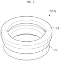
FIG. 2 is a perspective view of a sealing member of the present disclosure. -
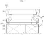
FIG. 3 is a cross-sectional view of a sealing member of the present disclosure. -
FIG. 4 is a diagram showing a connection structure between a sealing member and a battery according to the present disclosure. -
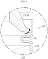
FIG. 5 is a partial enlarged view ofFIG. 4 . -
FIG. 6 is a diagram showing a connection structure between a sealing member and a battery according to the present disclosure when the battery includes a current collector plate. -
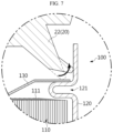
FIG. 7 is a partial enlarged view ofFIG. 6 . -
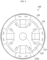
FIG. 8 is a top view of a battery including a current collector plate. -
FIG. 9 is a perspective view of a sealing member of the present disclosure, showing the sealing member shown inFIG. 3 having a core protection portion. -
FIG. 10 is a top view of the sealing member shown inFIG. 9 . - Hereinafter, exemplary embodiments of the present disclosure will be described in detail with reference to the accompanying drawings. Prior to the description, it should be understood that the terms or words used in the specification and the appended claims should not be construed as limited to general and dictionary meanings, but rather interpreted based on the meanings and concepts corresponding to the technical aspect of the present disclosure on the basis of the principle that the inventor is allowed to define terms appropriately for the best explanation.
- Therefore, the embodiments described herein and the illustrations in the accompanying drawings are an exemplary embodiment of the present disclosure to describe the technical aspect of the present disclosure and are not intended to be limiting, and thus it should be understood that a variety of other equivalents and modifications could have been made thereto at the time that the application was filed.
- In the drawings, the size of each element or specific parts of the elements is exaggerated, omitted or schematically illustrated for convenience of description and clarity. Accordingly, the size of each element does not necessarily reflect the actual size. When it is determined that a certain detailed description of relevant known functions or elements may unnecessarily obscure the subject matter of the present disclosure, the description is omitted. For reference, as used herein, the terms indicating directions are the terms on the basis of the elements in the accompanying drawings, and may be relative terms that are subject to change depending on the actual position or locations of the elements.
- The terms indicating directions such as upper, lower, left, right, front and rear are used for convenience of description, but it is obvious to those skilled in the art that the terms may change depending on the position of the stated element or an observer.
- A
pallet 1 according to an embodiment of the present disclosure will be described with reference toFIGS. 1 to 3 . -
FIG. 1 is a diagram showing the pallet according to an embodiment of the present disclosure, connected to a battery.FIG. 2 is a perspective view of a sealing member of the present disclosure.FIG. 3 is a cross-sectional view of the sealing member of the present disclosure. - Referring to
FIGS. 1 to 3 , thepallet 1 according to an embodiment of the present disclosure may be a pallet for electrolyte injection configured to connect an electrolyte feeder for feeding an electrolyte to an open portion on a side of ahousing 120 of thebattery 100. In the present disclosure, thebattery 100 into which the electrolyte is injected may be, for example, a cylindrical battery. - The
pallet 1 may include ahopper 10 and a sealingmember 20. Thehopper 10 may have a hollow structure to allow the electrolyte fed by the electrolyte feeder to pass therethrough. That is, thehopper 10 may act as a connector to connect the electrolyte feeder to thebattery 100 during electrolyte injection. Thehopper 10 may include a metal to ensure strength. However, the material of thehopper 10 is not limited thereto, and any material that maintains optimal strength and has chemical resistance to the electrolyte passing through thehopper 10 may be applied to thehopper 10. - The sealing
member 20 may include ahopper coupling portion 21 coupled to thehopper 10 and abattery sealing portion 22 configured to seal the open portion of thehousing 120. Thehopper coupling portion 21 may have a shape corresponding to an end on a side of thehopper 10. Thebattery sealing portion 22 may be configured to closely contact the inner surface of thehousing 120 of thebattery 100. The sealingmember 20 may include a flexible material to prevent electrolyte leakage at the coupled part of thehopper 10 and the sealingmember 20 and the contact part of the sealingmember 20 and thebattery 100. - The sealing
member 20 may include, for example, a rubber material. The sealingmember 20 may have a hollow structure having the internal space in communication with the internal space of thehopper 10. The sealingmember 20 may have an approximately cylindrical shape with the hollow center. - The
battery sealing portion 22 of the present disclosure may be configured to come into close contact with the inner surface of thehousing 120 as its end deforms outwards when pressed towards thebattery 100. - For example, the
battery sealing portion 22 may have an increasing inner diameter or inner width in a direction facing away from thehopper 10. Thebattery sealing portion 22 may have a decreasing thickness in a direction facing away from thehopper 10. - In case where the inner diameter increase structure of the
battery sealing portion 22 and/or the thickness decrease structure of thebattery sealing portion 22 is applied, when the sealingmember 20 is pressed towards thebattery 100, the end of thebattery sealing portion 22 may flexibly deform and come into close contact with the inner surface of thehousing 120 of thebattery 100. Accordingly, it may be possible to remove or reduce the electrolyte leakage risk in the process of injecting the electrolyte into thebattery 100. - Meanwhile, the
pallet 1 may further include an additional sealingmember 30 configured to connect thehopper 10 to the electrolyte feeder. The additional sealingmember 30 may prevent electrolyte leakage at the connected part of the electrolyte feeder and thehopper 10. - Subsequently, a shape change of the sealing
member 20 of the present disclosure when pressed towards thebattery 100 will be described with reference toFIGS. 4 and5 . -
FIG. 4 is a diagram showing the connection structure between the sealing member and the battery according to the present disclosure.FIG. 5 is a partial enlarged view ofFIG. 4 . - Referring to
FIGS. 4 and5 , thebattery sealing portion 22 may be configured such that when pressed towards thebattery 100, its end slides in the outward direction of thebattery 100 on abeading portion 121 of thehousing 120 of thebattery 100 and comes into close contact with the inner surface of thehousing 120 above thebeading portion 121. - The inner surface of the
beading portion 121 extending inward around thehousing 120 of thebattery 100 may not be a perfect flat surface, and other component may be disposed on thebeading portion 121. Accordingly, though the end of thebattery sealing portion 22 is in close contact with thebeading portion 121, a seal on the contact interface between thebattery sealing portion 22 and thebeading portion 121 may be incomplete. Accordingly, as described above, since the end of thebattery sealing portion 22 slides in the outward direction of thebattery 100 on thebeading portion 121 and comes into close contact with the inner surface of thehousing 120 above thebeading portion 121, it may be possible to further improve sealability. - Meanwhile, the motion of the
battery sealing portion 22 when thepallet 1 is pressed towards thebattery 100 may be, for example, obtained by the inner diameter increase structure of thebattery sealing portion 22 and/or the thickness decrease structure of thebattery sealing portion 22 as described above. Meanwhile, an angle of the inner surface of the end of thebattery sealing portion 22 with the vertical direction (parallel to the Z axis) may be, for example, approximately 10° to 30°. An angle of the outer surface of the end of thebattery sealing portion 22 with the vertical direction (parallel to the Z axis) may be, for example, approximately 40° to 60°. This angle condition is an angle condition before thebattery sealing portion 22 is pressed and deformed. - Subsequently, advantage(s) of the close contact between the
battery sealing portion 22 of the present disclosure and the inner surface of the sidewall of thehousing 120 will be described in more detail with reference toFIGS. 6 to 8 . -
FIG. 6 is a diagram showing the connection structure between the sealing member and the battery according to the present disclosure when the battery includes a current collector plate.FIG. 7 is a partial enlarged view ofFIG. 6 .FIG. 8 is a top view of the battery including the current collector plate. - Referring to
FIGS. 6 and7 , thepallet 1 of the present disclosure may be, for example, applied to thebattery 100 including thecurrent collector 130 disposed on thebeading portion 121 of thehousing 120. Thebattery 100 may include anelectrode assembly 110, thehousing 120 accommodating theelectrode assembly 110 and thecurrent collector 130 electrically connected to theelectrode assembly 110 and connected to thebeading portion 121 of thehousing 120. Thecurrent collector 130 may be, for example, coupled to anuncoated portion 111 on a surface of theelectrode assembly 110. Thecurrent collector 130 may have acurrent collector hole 130a. Thecurrent collector hole 130a may be formed approximately at the center of thecurrent collector 130. Thecurrent collector hole 130a may be formed at a location corresponding to a winding center hole of theelectrode assembly 110. - When the
current collector 130 is disposed on thebeading portion 121 of thehousing 120, the upper surface of thebeading portion 121 may be uneven due to thecurrent collector 130. Additionally, when thecurrent collector 130 is welded to thebeading portion 121, the upper surface of thebeading portion 121 may have lower flatness due to a weld bead. - Referring to
FIG. 8 , thecurrent collector 130 may be, for example, discontinuously disposed on thebeading portion 121 along the circumferential direction of thehousing 120. When thebattery 100 has the above-described structure, the flatness on thebeading portion 121 may be lower. - In case where the flatness of the upper surface of the
beading portion 121 is low, when the connected part between thepallet 1 and thebattery 100 is sealed by bringing thebattery sealing portion 22 into close contact with thebeading portion 121, sealability may be low, and as a consequence, electrolyte leakage may occur during electrolyte injection. Accordingly, as in an embodiment of the present disclosure, due to thebattery sealing portion 22 configured with its end in close contact with the inner surface of the sidewall of thehousing 120 above thebeading portion 121, it may be possible to ensure further improved sealability. - Subsequently, the sealing
member 20 having a different structure fromFIG. 2 will be described with reference toFIGS. 9 and10 together withFIG. 1 . -
FIG. 9 is a perspective view of the sealing member of the present disclosure, showing the sealing member shown inFIG. 3 having a core protection portion.FIG. 10 is a top view of the sealing member shown inFIG. 9 . - Referring to
FIGS. 9 and10 together withFIG. 1 , the sealingmember 20 may include thecore protection portion 23. Thecore protection portion 23 may be configured to decrease the cross-sectional area of the internal space of the sealingmember 20 through which the electrolyte passes. For example, thecore protection portion 23 may be configured to go across the internal space of the sealingmember 20. For example, thecore protection portion 23 may be configured to pass through approximately the central area of the internal space of the sealingmember 20. Thecore protection portion 23 may be located such that thecore protection portion 23 overlaps the winding center hole of theelectrode assembly 110 accommodated in thebattery 100 at least in part. - The
core protection portion 23 may include a plurality ofbridges 23a extending outwards approximately radially from approximately the central area of the internal space of the sealingmember 20. Thecore protection portion 23 may include acore cover 23b disposed approximately at the central area of the internal space of the sealingmember 20. Thecore cover 23b may be configured to cover at least part of the winding center hole at the core of theelectrode assembly 110 of thebattery 100. Thecore cover 23b may be supported by thebridges 23a. - According to the above-described configuration of the sealing
member 20, it may be possible to reduce the flow volume and/or flow rate when the electrolyte passing through thepallet 1 flows into the winding center hole of the core of theelectrode assembly 110. Alternatively, it may be possible to prevent the electrolyte from directly flowing into the winding center hole of theelectrode assembly 110 according to the size and location of thebridges 23a and/or thecore cover 23b of thecore protection portion 23. Accordingly, it may be possible to prevent or minimize damage to the separator disposed around the inner wall of the winding center hole of theelectrode assembly 110 due to the electrolyte injection pressure. - Subsequently, an electrolyte injection method according to an embodiment of the present disclosure will be described. The electrolyte injection method of the present disclosure will be described with reference to
FIGS. 1 to 10 . - The electrolyte injection method of the present disclosure relates to a method for injecting the electrolyte into the
battery 100 through the open portion on a side of thehousing 120 of thebattery 100, and may include an insertion step, a seating step, a close contact step and an injection step. - The insertion step may be the step of inserting the
pallet 1 for electrolyte injection into the open portion of thehousing 120. The seating step may be the step of seating the sealingmember 20 of thepallet 1 on thebeading portion 121 of thehousing 120. The close contact step may be the step of pressing the sealingmember 20 towards thebeading portion 121 so that the sealingmember 20 may slide on thebeading portion 121 and come into close contact with the inner surface of thehousing 120 above thebeading portion 121. The injection step may be the step of injecting the electrolyte into thehousing 120 through thepallet 1. - The close contact step may be the step of pressing the sealing
member 20 with its end in contact with thebeading portion 121 so that the end of the sealingmember 20 may deform outwards to bring the sealingmember 20 into close contact with the inner surface of thehousing 120. - In the electrolyte injection method of the present disclosure, the
battery 100 may include thecurrent collector 130 electrically connected to theelectrode assembly 110 accommodated in thehousing 120. Thecurrent collector 130 may be disposed on thebeading portion 121. Thecurrent collector 130 may be discontinuously disposed on thebeading portion 121 along the circumferential direction of thehousing 120. - The injection step may be the step of dispersing the electrolyte injection pressure facing the winding center hole of the
electrode assembly 110 accommodated in thehousing 120 using thecore protection portion 23 configured to pass through the central area of the internal space of the sealingmember 20. - While the present disclosure has been hereinabove described with regard to a limited number of embodiments and drawings, the present disclosure is not limited thereto and it is apparent that a variety of changes and modifications may be made by those skilled in the art within the technical aspect of the present disclosure and the scope of the appended claims and their equivalents.
-
- 1: Pallet
- 10: Hopper
- 20: Sealing member
- 21: Hopper coupling portion
- 22: Battery sealing portion
- 23: Core protection portion
- 23a: Bridge
- 23b: Core cover
- 100: Battery
- 111: Uncoated portion
- 110: Electrode assembly
- 120: Housing
- 121: Beading portion
- 130: Current collector
- 130a: Current collector hole
Claims (15)
- A pallet for electrolyte injection, configured to connect an electrolyte feeder for feeding an electrolyte to an open portion on a side of a housing of a battery, the pallet comprising:a hopper having a hollow structure; anda sealing member including a hopper coupling portion coupled to the hopper and a battery sealing portion configured to seal the open portion, wherein the battery sealing portion is configured to come into close contact with an inner surface of the housing of the battery.
- The pallet according to claim 1, wherein the sealing member has a hollow structure having an internal space in communication with an internal space of the hopper.
- The pallet according to claim 1, wherein the battery sealing portion is configured to come into close contact with the inner surface of the battery housing as an end of the battery sealing portion deforms outwards when pressed towards the battery.
- The pallet according to claim 1, wherein the battery sealing portion is configured to increase in inner diameter or an inner width in a direction facing away from the hopper.
- The pallet according to claim 1, wherein the battery sealing portion is configured to decrease in thickness in a direction facing away from the hopper.
- The pallet according to claim 1, wherein the battery sealing portion is configured such that when pressed towards the battery, an end of the battery sealing portion slides in an outward direction of the battery on a beading portion of the housing of the battery and comes into close contact with the inner surface of the housing above the beading portion.
- The pallet according to claim 1, wherein the sealing member includes a core protection portion configured to reduce a cross-sectional area of an internal space of the sealing member through which the electrolyte passes.
- The pallet according to claim 7, wherein the core protection portion is configured to go across the internal space of the sealing member.
- The pallet according to claim 8, wherein the core protection portion is configured to pass through a central area of the internal space of the sealing member.
- The pallet according to claim 8, wherein the core protection portion is located such that the core protection portion overlaps a winding center hole of an electrode assembly accommodated in the battery at least in part.
- An electrolyte injection method for injecting an electrolyte into a battery through an open portion on a side of a housing of a battery, the electrolyte injection method comprising:an insertion step of inserting a pallet for electrolyte injection into the open portion;a seating step of seating a sealing member of the pallet on a beading portion of the housing;a close contact step of pressing the sealing member towards the beading portion so that an end of the sealing member slides on the beading portion and comes into close contact with an inner surface of the housing above the beading portion; andan injection step of injecting the electrolyte into the housing through the pallet.
- The electrolyte injection method according to claim 11, wherein the close contact step comprises pressing the sealing member with the end of the sealing member in contact with the beading portion so that the end of the sealing member deforms outwards to bring the sealing member into close contact with the inner surface of the housing.
- The electrolyte injection method according to claim 11, wherein the battery includes a current collector electrically connected to an electrode assembly accommodated in the housing, and
wherein the current collector is located on the beading portion. - The electrolyte injection method according to claim 13, wherein the current collector is discontinuously disposed on the beading portion along a circumferential direction of the housing.
- The electrolyte injection method according to claim 11, wherein the injection step comprises dispersing an electrolyte injection pressure facing a winding center hole of an electrode assembly accommodated in the housing using a core protection portion configured to pass through a central area of an internal space of the sealing member.
Applications Claiming Priority (2)
| Application Number | Priority Date | Filing Date | Title |
|---|---|---|---|
| KR20220087614 | 2022-07-15 | ||
| PCT/KR2023/010219 WO2024014938A1 (en) | 2022-07-15 | 2023-07-17 | Pellets for electrolyte injection and electrolyte injection method |
Publications (2)
| Publication Number | Publication Date |
|---|---|
| EP4518018A1 true EP4518018A1 (en) | 2025-03-05 |
| EP4518018A4 EP4518018A4 (en) | 2025-08-13 |
Family
ID=89537166
Family Applications (1)
| Application Number | Title | Priority Date | Filing Date |
|---|---|---|---|
| EP23840029.5A Pending EP4518018A4 (en) | 2022-07-15 | 2023-07-17 | PELLETS FOR ELECTROLYTE INJECTION AND ELECTROLYTE INJECTION PROCESS |
Country Status (7)
| Country | Link |
|---|---|
| US (1) | US20250323400A1 (en) |
| EP (1) | EP4518018A4 (en) |
| JP (1) | JP2025523690A (en) |
| KR (1) | KR20240010441A (en) |
| CN (1) | CN119234352A (en) |
| CA (1) | CA3257819A1 (en) |
| WO (1) | WO2024014938A1 (en) |
Families Citing this family (1)
| Publication number | Priority date | Publication date | Assignee | Title |
|---|---|---|---|---|
| KR20260055699A (en) * | 2024-10-17 | 2026-04-24 | 주식회사 엘지에너지솔루션 | Hopper and electrolyte injection pallet including the same |
Family Cites Families (12)
| Publication number | Priority date | Publication date | Assignee | Title |
|---|---|---|---|---|
| KR100599792B1 (en) * | 2004-05-19 | 2006-07-13 | 삼성에스디아이 주식회사 | Secondary Battery, Electrode Assembly and Current Collecting Plate Used in the Same |
| JP2007165170A (en) * | 2005-12-15 | 2007-06-28 | Matsushita Electric Ind Co Ltd | Secondary battery manufacturing method and manufacturing apparatus thereof |
| JP2008091065A (en) * | 2006-09-29 | 2008-04-17 | Matsushita Electric Ind Co Ltd | Lithium secondary battery pouring method and pouring device |
| JP2014022073A (en) * | 2012-07-12 | 2014-02-03 | Hitachi Vehicle Energy Ltd | Manufacturing method and apparatus for square secondary battery |
| CN105024038A (en) * | 2014-04-29 | 2015-11-04 | 江苏智航新能源有限公司 | Cluster type electrolyte injection tool |
| CN204179142U (en) * | 2014-11-20 | 2015-02-25 | 东莞市振华新能源科技有限公司 | A leak-proof injection cup for lithium-ion cylindrical batteries |
| CN205194777U (en) * | 2015-11-24 | 2016-04-27 | 赣州雄博新能源科技有限公司 | High accuracy battery solution injection device |
| JP7055648B2 (en) * | 2018-01-26 | 2022-04-18 | 三洋電機株式会社 | Power storage device |
| KR101876834B1 (en) * | 2018-02-26 | 2018-07-11 | (주)하나기술 | Apparatus for injecting electrolyte and method thereof |
| CN212380531U (en) * | 2020-07-08 | 2021-01-19 | 宁波久鼎新能源科技有限公司 | Anti-overflow cap for battery |
| KR20220087614A (en) | 2020-12-17 | 2022-06-27 | 현대자동차주식회사 | Power transmission system of hybrid electric vehicle |
| CN112952307B (en) * | 2021-03-30 | 2022-06-07 | 天能电池集团股份有限公司 | Acid adding and formation system for storage battery |
-
2023
- 2023-07-17 JP JP2025501674A patent/JP2025523690A/en active Pending
- 2023-07-17 EP EP23840029.5A patent/EP4518018A4/en active Pending
- 2023-07-17 CA CA3257819A patent/CA3257819A1/en active Pending
- 2023-07-17 WO PCT/KR2023/010219 patent/WO2024014938A1/en not_active Ceased
- 2023-07-17 CN CN202380041481.8A patent/CN119234352A/en active Pending
- 2023-07-17 US US18/867,226 patent/US20250323400A1/en active Pending
- 2023-07-17 KR KR1020230092727A patent/KR20240010441A/en active Pending
Also Published As
| Publication number | Publication date |
|---|---|
| JP2025523690A (en) | 2025-07-23 |
| WO2024014938A1 (en) | 2024-01-18 |
| US20250323400A1 (en) | 2025-10-16 |
| CA3257819A1 (en) | 2025-03-19 |
| CN119234352A (en) | 2024-12-31 |
| EP4518018A4 (en) | 2025-08-13 |
| KR20240010441A (en) | 2024-01-23 |
Similar Documents
| Publication | Publication Date | Title |
|---|---|---|
| CN101083310B (en) | Sealed battery | |
| CN101764246B (en) | Secondary battery | |
| CN217158371U (en) | Top cover assembly and single battery | |
| US6632562B1 (en) | Battery module composed of a plurality of serially connected cells, and method and structure for connecting cells | |
| CN118575357A (en) | Secondary battery | |
| CN116435675B (en) | Cylindrical secondary battery | |
| US8592077B2 (en) | Rechargeable battery | |
| EP4331036B1 (en) | Cylindrical battery cell, battery and method for forming cylindrical battery cell | |
| WO2018124152A1 (en) | Coin-type battery and manufacturing method thereof | |
| US12494534B2 (en) | Cap assembly, secondary battery comprising the same, and battery pack | |
| CN113875056A (en) | Method for manufacturing secondary battery and method for manufacturing battery pack including the same | |
| US20250323400A1 (en) | Pallet for Electrolyte Injection and Electrolyte Injection Method | |
| CN120413921A (en) | Cylindrical secondary batteries | |
| US20250167412A1 (en) | Electrolyte injection o-ring and cylindrical battery manufacturing method using the same | |
| EP4664671A1 (en) | Pellets for electrolyte injection and electrolyte injection method | |
| CN119627322A (en) | Secondary battery | |
| WO2024053272A1 (en) | Cylindrical battery gasket, and cylindrical battery provided with said gasket | |
| US9190637B2 (en) | Rechargeable battery | |
| KR20250101752A (en) | Pellets for electrolyte injection and electrolyte injection method | |
| EP4693721A1 (en) | Electrolyte injection jig and electrolyte injection method | |
| CN223193879U (en) | Cover plate assembly, single battery and electric equipment | |
| EP4411976A1 (en) | Power storage device and method for manufacturing power storage device | |
| EP4358283A1 (en) | Cap assembly, cylindrical secondary battery including same, and method for manufacturing cylindrical secondary battery including same | |
| KR102887618B1 (en) | Secondary Battery | |
| CN120814110A (en) | Battery cell, battery pack including the same, vehicle, and method of manufacturing battery cell |
Legal Events
| Date | Code | Title | Description |
|---|---|---|---|
| STAA | Information on the status of an ep patent application or granted ep patent |
Free format text: STATUS: THE INTERNATIONAL PUBLICATION HAS BEEN MADE |
|
| PUAI | Public reference made under article 153(3) epc to a published international application that has entered the european phase |
Free format text: ORIGINAL CODE: 0009012 |
|
| STAA | Information on the status of an ep patent application or granted ep patent |
Free format text: STATUS: REQUEST FOR EXAMINATION WAS MADE |
|
| 17P | Request for examination filed |
Effective date: 20241127 |
|
| AK | Designated contracting states |
Kind code of ref document: A1 Designated state(s): AL AT BE BG CH CY CZ DE DK EE ES FI FR GB GR HR HU IE IS IT LI LT LU LV MC ME MK MT NL NO PL PT RO RS SE SI SK SM TR |
|
| A4 | Supplementary search report drawn up and despatched |
Effective date: 20250716 |
|
| RIC1 | Information provided on ipc code assigned before grant |
Ipc: H01M 50/609 20210101AFI20250710BHEP Ipc: H01M 50/627 20210101ALI20250710BHEP Ipc: H01M 50/107 20210101ALI20250710BHEP Ipc: H01M 50/167 20210101ALI20250710BHEP |
|
| DAV | Request for validation of the european patent (deleted) | ||
| DAX | Request for extension of the european patent (deleted) | ||
| STAA | Information on the status of an ep patent application or granted ep patent |
Free format text: STATUS: EXAMINATION IS IN PROGRESS |
|
| 17Q | First examination report despatched |
Effective date: 20260309 |