EP4518014A1 - Batteriemodul, nageleindringschutzverfahren für batteriemodul und fahrzeug - Google Patents
Batteriemodul, nageleindringschutzverfahren für batteriemodul und fahrzeug Download PDFInfo
- Publication number
- EP4518014A1 EP4518014A1 EP23794706.4A EP23794706A EP4518014A1 EP 4518014 A1 EP4518014 A1 EP 4518014A1 EP 23794706 A EP23794706 A EP 23794706A EP 4518014 A1 EP4518014 A1 EP 4518014A1
- Authority
- EP
- European Patent Office
- Prior art keywords
- battery core
- battery
- metal member
- battery module
- core group
- Prior art date
- Legal status (The legal status is an assumption and is not a legal conclusion. Google has not performed a legal analysis and makes no representation as to the accuracy of the status listed.)
- Pending
Links
Images


Classifications
-
- H—ELECTRICITY
- H01—ELECTRIC ELEMENTS
- H01M—PROCESSES OR MEANS, e.g. BATTERIES, FOR THE DIRECT CONVERSION OF CHEMICAL ENERGY INTO ELECTRICAL ENERGY
- H01M50/00—Constructional details or processes of manufacture of the non-active parts of electrochemical cells other than fuel cells, e.g. hybrid cells
- H01M50/20—Mountings; Secondary casings or frames; Racks, modules or packs; Suspension devices; Shock absorbers; Transport or carrying devices; Holders
- H01M50/204—Racks, modules or packs for multiple batteries or multiple cells
- H01M50/207—Racks, modules or packs for multiple batteries or multiple cells characterised by their shape
- H01M50/209—Racks, modules or packs for multiple batteries or multiple cells characterised by their shape adapted for prismatic or rectangular cells
-
- H—ELECTRICITY
- H01—ELECTRIC ELEMENTS
- H01M—PROCESSES OR MEANS, e.g. BATTERIES, FOR THE DIRECT CONVERSION OF CHEMICAL ENERGY INTO ELECTRICAL ENERGY
- H01M50/00—Constructional details or processes of manufacture of the non-active parts of electrochemical cells other than fuel cells, e.g. hybrid cells
- H01M50/20—Mountings; Secondary casings or frames; Racks, modules or packs; Suspension devices; Shock absorbers; Transport or carrying devices; Holders
- H01M50/204—Racks, modules or packs for multiple batteries or multiple cells
- H01M50/207—Racks, modules or packs for multiple batteries or multiple cells characterised by their shape
- H01M50/211—Racks, modules or packs for multiple batteries or multiple cells characterised by their shape adapted for pouch cells
-
- H—ELECTRICITY
- H01—ELECTRIC ELEMENTS
- H01M—PROCESSES OR MEANS, e.g. BATTERIES, FOR THE DIRECT CONVERSION OF CHEMICAL ENERGY INTO ELECTRICAL ENERGY
- H01M50/00—Constructional details or processes of manufacture of the non-active parts of electrochemical cells other than fuel cells, e.g. hybrid cells
- H01M50/20—Mountings; Secondary casings or frames; Racks, modules or packs; Suspension devices; Shock absorbers; Transport or carrying devices; Holders
- H01M50/249—Mountings; Secondary casings or frames; Racks, modules or packs; Suspension devices; Shock absorbers; Transport or carrying devices; Holders specially adapted for aircraft or vehicles, e.g. cars or trains
-
- H—ELECTRICITY
- H01—ELECTRIC ELEMENTS
- H01M—PROCESSES OR MEANS, e.g. BATTERIES, FOR THE DIRECT CONVERSION OF CHEMICAL ENERGY INTO ELECTRICAL ENERGY
- H01M50/00—Constructional details or processes of manufacture of the non-active parts of electrochemical cells other than fuel cells, e.g. hybrid cells
- H01M50/20—Mountings; Secondary casings or frames; Racks, modules or packs; Suspension devices; Shock absorbers; Transport or carrying devices; Holders
- H01M50/258—Modular batteries; Casings provided with means for assembling
-
- H—ELECTRICITY
- H01—ELECTRIC ELEMENTS
- H01M—PROCESSES OR MEANS, e.g. BATTERIES, FOR THE DIRECT CONVERSION OF CHEMICAL ENERGY INTO ELECTRICAL ENERGY
- H01M50/00—Constructional details or processes of manufacture of the non-active parts of electrochemical cells other than fuel cells, e.g. hybrid cells
- H01M50/50—Current conducting connections for cells or batteries
- H01M50/502—Interconnectors for connecting terminals of adjacent batteries; Interconnectors for connecting cells outside a battery casing
- H01M50/509—Interconnectors for connecting terminals of adjacent batteries; Interconnectors for connecting cells outside a battery casing characterised by the type of connection, e.g. mixed connections
- H01M50/51—Connection only in series
-
- H—ELECTRICITY
- H01—ELECTRIC ELEMENTS
- H01M—PROCESSES OR MEANS, e.g. BATTERIES, FOR THE DIRECT CONVERSION OF CHEMICAL ENERGY INTO ELECTRICAL ENERGY
- H01M50/00—Constructional details or processes of manufacture of the non-active parts of electrochemical cells other than fuel cells, e.g. hybrid cells
- H01M50/50—Current conducting connections for cells or batteries
- H01M50/572—Means for preventing undesired use or discharge
- H01M50/574—Devices or arrangements for the interruption of current
- H01M50/583—Devices or arrangements for the interruption of current in response to current, e.g. fuses
-
- H—ELECTRICITY
- H01—ELECTRIC ELEMENTS
- H01M—PROCESSES OR MEANS, e.g. BATTERIES, FOR THE DIRECT CONVERSION OF CHEMICAL ENERGY INTO ELECTRICAL ENERGY
- H01M50/00—Constructional details or processes of manufacture of the non-active parts of electrochemical cells other than fuel cells, e.g. hybrid cells
- H01M50/50—Current conducting connections for cells or batteries
- H01M50/572—Means for preventing undesired use or discharge
- H01M50/584—Means for preventing undesired use or discharge for preventing incorrect connections inside or outside the batteries
- H01M50/59—Means for preventing undesired use or discharge for preventing incorrect connections inside or outside the batteries characterised by the protection means
- H01M50/593—Spacers; Insulating plates
-
- H—ELECTRICITY
- H01—ELECTRIC ELEMENTS
- H01M—PROCESSES OR MEANS, e.g. BATTERIES, FOR THE DIRECT CONVERSION OF CHEMICAL ENERGY INTO ELECTRICAL ENERGY
- H01M2200/00—Safety devices for primary or secondary batteries
-
- H—ELECTRICITY
- H01—ELECTRIC ELEMENTS
- H01M—PROCESSES OR MEANS, e.g. BATTERIES, FOR THE DIRECT CONVERSION OF CHEMICAL ENERGY INTO ELECTRICAL ENERGY
- H01M2200/00—Safety devices for primary or secondary batteries
- H01M2200/10—Temperature sensitive devices
- H01M2200/103—Fuse
-
- H—ELECTRICITY
- H01—ELECTRIC ELEMENTS
- H01M—PROCESSES OR MEANS, e.g. BATTERIES, FOR THE DIRECT CONVERSION OF CHEMICAL ENERGY INTO ELECTRICAL ENERGY
- H01M2220/00—Batteries for particular applications
- H01M2220/20—Batteries in motive systems, e.g. vehicle, ship, plane
-
- Y—GENERAL TAGGING OF NEW TECHNOLOGICAL DEVELOPMENTS; GENERAL TAGGING OF CROSS-SECTIONAL TECHNOLOGIES SPANNING OVER SEVERAL SECTIONS OF THE IPC; TECHNICAL SUBJECTS COVERED BY FORMER USPC CROSS-REFERENCE ART COLLECTIONS [XRACs] AND DIGESTS
- Y02—TECHNOLOGIES OR APPLICATIONS FOR MITIGATION OR ADAPTATION AGAINST CLIMATE CHANGE
- Y02E—REDUCTION OF GREENHOUSE GAS [GHG] EMISSIONS, RELATED TO ENERGY GENERATION, TRANSMISSION OR DISTRIBUTION
- Y02E60/00—Enabling technologies; Technologies with a potential or indirect contribution to GHG emissions mitigation
- Y02E60/10—Energy storage using batteries
Definitions
- the present disclosure relates to a battery module, a nail penetration protection method for a battery module, and a vehicle having the battery module.
- lithium iron phosphate batteries When existing batteries, particularly, lithium iron phosphate batteries, are subjected to nail penetration tests, a single lithium iron phosphate battery is not prone to a fire or explosion under a nail penetration condition and can pass the nail penetration tests.
- batteries are connected in series, particularly, when a number of batteries connected in series is greater than or equal to 3, violent arcing, fire, and combustion may occur during nail penetration tests.
- An objective of the present disclosure is to provide a battery module, to resolve a technical problem that a battery in the related art is prone to arcing, fire, and combustion in a nail penetration test.
- Another objective of the present disclosure to provide a nail penetration protection method for a battery module.
- the nail penetration protection method can improve safety performance of the battery module during a nail penetration test.
- Still another objective of the present disclosure is to provide a vehicle, having the foregoing battery module, which can improve safety performance.
- a battery module including multiple battery cores, a guard assembly, and a protection component.
- the multiple battery cores are connected in series.
- the multiple battery cores include a first battery core group and a second battery core group oppositely arranged.
- the first battery core group and the second battery core group are each provided with at least one of the battery cores.
- the guard assembly is located between the first battery core group and the second battery core group, and includes a first metal member, a first insulation member, and a second metal member that are stacked.
- the first metal member is arranged opposite to at least one of the battery cores in the first battery core group, and the second metal member is arranged opposite to at least one of the battery cores in the second battery core group.
- the protection component is arranged between two of the battery cores adjacently arranged, and configured to cut off a circuit.
- a test steel nail sequentially passes through the battery core corresponding to the first metal member in the first battery core group, the first metal member, the first insulation member, and the second metal member, a loop is formed in the battery module.
- a short-circuit loop is added to the battery module.
- the first insulation member includes a first insulation layer and a second insulation layer
- the guard assembly includes a first composite layer and a second composite layer.
- the first composite layer includes the first insulation layer and the first metal member
- the second composite layer includes the second insulation layer and the second metal member.
- the guard assembly further includes a second insulation member.
- the second insulation member is located between the first battery core group and the first metal member, and/or located between the second battery core group and the second metal member.
- the protection component is a fuse.
- the first metal member and the second metal member are each an elongated sheet-shaped body. An end of the sheet-shaped body along a length direction thereof is connected to a terminal of the battery core.
- a position at which the sheet-shaped body is connected to the battery core in the corresponding first battery core group or second battery core group is adjustable.
- the sheet-shaped body includes a body and an electrical connection piece.
- the body is in an elongated shape, and the electrical connection piece is located at an end of the body along a length direction.
- a length of the electrical connection piece is less than a width of the body, and the electrical connection piece is a bent member.
- a number of the battery cores in the first battery core group is equal to a number of the battery cores in the second battery core group.
- a nail penetration protection method for a battery module is provided.
- the battery module is the battery module according to any one of the foregoing.
- the nail penetration protection method includes the following steps: A loop is formed in the battery module when a test steel nail sequentially penetrates through the battery core corresponding to the first metal member in the first battery core group, the first metal member, and the first insulation member to the second metal member. A short-circuit loop is added to the battery module when the test steel nail penetrates the battery core corresponding to the second metal member in the second battery core group.
- a vehicle includes the battery module according to any one of the foregoing.
- a guard assembly is arranged between a first battery core group and a second battery core group oppositely arranged. Through cooperation between the guard assembly and a protection component, arcing, fire, and combustion can be avoided during a nail penetration test when multiple battery cores are connected in series.
- the present disclosure is an invention made by the inventor based on the following facts.
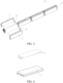
- FIG. 1 and FIG. 2 show overall structural diagrams of a battery module in the related art.
- FIG. 1 shows a blade-shaped module structure in the related art.
- the module has positive and negative poles on a same side, and is a U-shaped series structure.
- the U-shaped structure has a U-shaped safety structure 3 at a tail.
- a steel nail enters from a battery 1 and continues moving forward to penetrate through the battery 2.
- the steel nail connects positive and negative pole pieces in the battery 1.
- the steel nail serves as a conductor.
- a battery module 100 according to an embodiment of the present disclosure is described below with reference to the accompanying drawings.
- the battery module 100 includes multiple battery cores, a guard assembly, and a protection component.
- the multiple battery cores are connected in series.
- the multiple battery cores include a first battery core group and a second battery core group oppositely arranged.
- the first battery core group and the second battery core group are each provided with at least one of the battery cores.
- the guard assembly is located between the first battery core group and the second battery core group.
- the guard assembly includes a first metal member 31, a first insulation member, and a second metal member 41 that are stacked.
- the first metal member 31 is arranged opposite to at least one of the battery cores in the first battery core group, and the second metal member 41 is arranged opposite to at least one of the battery cores in the second battery core group.
- the protection component 20 is arranged between two of the battery cores adjacently arranged. The protection component 20 can cut off a circuit.
- the battery module 100 mainly includes multiple battery cores, a guard assembly, and a protection component.
- the multiple battery cores are connected in series.
- the battery module 100 in this embodiment of the present disclosure may be a circuit connected in series, or may be a circuit connected in series and parallel.
- the first battery core in the multiple battery cores may be electrically connected to a total positive pole of the battery module 100, and the last battery core in the multiple battery cores may be electrically connected to a total negative pole of the battery module 100.
- the multiple battery cores connected in series may form a battery core string.
- the first battery core in the battery core string can be electrically connected to the total positive pole, and the last battery core can be electrically connected to the total negative pole.
- the total positive pole and the total negative pole of the battery module 100 may be located on a same side.
- the battery module 100 may be substantially a U-shaped series-connection structure.
- the battery core string includes a first battery core group and a second battery core group oppositely arranged.
- the first battery core group includes at least one battery core
- the second battery core group also includes at least one battery core.
- one battery core in the first battery core group is defined as a first battery core 11
- one battery core in the second battery core group is defined as a second battery core 12.
- the first battery core 11 and the second battery core 12 are oppositely arranged.
- the first battery core 11 and the second battery core 12 respectively extend along a horizontal direction, and the second battery core 12 is located above or below the first battery core 11.
- the first battery core group includes at least one battery core
- the second battery core group includes at least one battery core.
- a guard assembly is arranged between the first battery core group and the second battery core group. A position of the guard assembly is described below by using examples.
- the first battery core group includes 4 battery cores
- the second battery core group includes 4 battery cores.
- the first battery core 11 of the first battery core group is connected to the total positive pole
- the second battery core 12 is connected to the total negative pole.
- the guard assembly is located between the first battery core 11 and the second battery core 12, and the guard assembly does not exceed the first battery core 11 and the second battery core 12.
- the first battery core group includes 4 battery cores
- the second battery core group includes 4 battery cores.
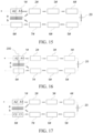
- the battery core string is divided into a battery core 1#, a battery core 2#, a battery core 3#, a battery core 4#, a battery core 5#, a battery core 6#, a battery core 7#, and a battery core 8#.
- the first battery core group includes the battery core 1#, the battery core 2#, the battery core 3#, and the battery core 4#.
- the second battery core group includes the battery core 5#, the battery core 6#, the battery core 7#, and the battery core 8#.
- the battery core 1# is connected to the total positive pole
- the battery core 8# is connected to the total negative pole.
- the battery core 2# and the battery core 7# are oppositely arranged.
- the battery core 3# and the battery core 6# are oppositely arranged.
- the battery core 4# and the battery core 5# are oppositely arranged.
- One side of the guard assembly is arranged opposite to the battery core# 2, and an other side of the guard assembly is arranged opposite to the battery core# 7.
- the first battery core group includes 4 battery cores
- the second battery core group includes 4 battery cores.
- the battery core string is divided into a battery core 1#, a battery core 2#, a battery core 3#, a battery core 4#, a battery core 5#, a battery core 6#, a battery core 7#, and a battery core 8#.
- the first battery core group includes the battery core 1#, the battery core 2#, the battery core 3#, and the battery core 4#.
- the second battery core group includes the battery core 5#, the battery core 6#, the battery core 7#, and the battery core 8#.
- the battery core 1# is connected to the total positive pole
- the battery core 8# is connected to the total negative pole.
- the battery core 2# and the battery core 7# are oppositely arranged.
- the battery core 3# and the battery core 6# are oppositely arranged.
- the battery core 4# and the battery core 5# are oppositely arranged.
- One side of the guard assembly is arranged opposite to the battery core 3#, and an other side of the guard assembly is arranged opposite to the battery core 6#.
- the first battery core group includes 4 battery cores
- the second battery core group includes 4 battery cores.
- the battery core string is divided into a battery core 1#, a battery core 2#, a battery core 3#, a battery core 4#, a battery core 5#, a battery core 6#, a battery core 7#, and a battery core 8#.
- the first battery core group includes the battery core 1#, the battery core 2#, the battery core 3#, and the battery core 4#.
- the second battery core group includes the battery core 5#, the battery core 6#, the battery core 7#, and the battery core 8#.
- the battery core 1# is connected to the total positive pole
- the battery core 8# is connected to the total negative pole.
- the battery core 2# and the battery core 7# are oppositely arranged.
- the battery core 3# and the battery core 6# are oppositely arranged.
- the battery core 4# and the battery core 5# are oppositely arranged.
- One side of the guard assembly is opposite to both the battery core 2# and the battery core 3#, and an other side of the guard assembly is opposite to both the battery core 7# and the battery core 6#.
- the first battery core group includes 4 battery cores
- the second battery core group includes 4 battery cores.
- the battery core string is divided into a battery core 1#, a battery core 2#, a battery core 3#, a battery core 4#, a battery core 5#, a battery core 6#, a battery core 7#, and a battery core 8#.
- the first battery core group includes the battery core 1#, the battery core 2#, the battery core 3#, and the battery core 4#.
- the second battery core group includes the battery core 5#, the battery core 6#, the battery core 7#, and the battery core 8#.
- the battery core 1# is connected to the total positive pole
- the battery core 8# is connected to the total negative pole.
- the battery core 2# and the battery core 7# are oppositely arranged.
- the battery core 3# and the battery core 6# are oppositely arranged.
- the battery core 4# and the battery core 5# are oppositely arranged.
- One side of the guard assembly is opposite to all of the battery core 1#, the battery core 2#, the battery core 3#, and the battery core 4#, and an other side of the guard assembly is opposite to all of the battery core 8#, the battery core 7#, the battery core 6#, and the battery core 5#.
- a first metal member 31, a first insulation member, and a second metal member 41 may be arranged between the first battery core 11 and the second battery core 12.
- the first metal member 31, the first insulation member, and the second metal member 41 are stacked.
- the second battery core 12, the second metal member 41, the first insulation member, the first metal member 31, and the first battery core 11 are sequentially distributed from bottom to top.
- the first metal member 31 is arranged opposite to the first battery core 11, and the second metal member 41 is arranged opposite to the second battery core 12. It should be noted that the first metal member 31 may be connected to a terminal of the first battery core 11 or connected to a terminal of a battery core adjacent to the first battery core 11 or the like, and the second metal member 41 may also be connected to a terminal of the second battery core 12 or connected to a terminal of a battery core adjacent to the second battery core 12 or the like.
- a protection component 20 is arranged between two battery cores adjacently arranged in the multiple battery cores.
- a fuse or a protection structure formed by a circuit structure of the circuit may be selected as the protection component 20 according to an actual use situation.
- the protection component 20 of this structure may be configured to perform battery overcurrent protection, thereby improving use safety of the battery module 100.
- a fuse or an overcurrent structural member with a small cross-sectional area may be selected as the protection component 20.
- the test steel nail 200 penetrates upward from the first battery core 11, first enters the first battery core 11, and then continues moving forward to penetrate through the first metal member 31 to the second metal member 41.
- the high temperature on the test steel nail 200 melts through the first insulation member between the first metal member 31 and the second metal member 41, thereby increasing a contact area between the first metal member 31 and the second metal member 41, and forming a loop among the first battery core 11, the first metal member 31, the second metal member 41, the protection component 20, and the like in advance.
- the battery core in the present disclosure may be a lithium iron phosphate battery or a ternary battery such as a lithium manganate battery.
- the guard assembly is arranged between the first battery core group and the second battery core group oppositely arranged.
- the guard assembly Through cooperation between the guard assembly and the protection component, it is ensured that a circuit is cut off in time during a nail penetration test when multiple battery cores are connected in series, for example, when a number of battery cores connected in series is greater than or equal to 3, thereby avoiding arcing, fire, and combustion.
- the first insulation member includes a first insulation layer 32 and a second insulation layer 42
- the guard assembly includes a first composite layer 30 and a second composite layer 40.
- the first composite layer 30 includes the first insulation layer 32 and the first metal member 31
- the second composite layer 40 includes the second insulation layer 42 and the second metal member 41. That is, the first composite layer 30 includes the first insulation layer 32 and the first metal member 31.
- the first composite layer 30 may include the first insulation layer 32 and the first metal member 31, or may include another structure, for example, a second insulation member 50.
- the first composite layer 30 includes the first insulation layer 32 and the first metal member 31, and when an outer periphery of the first battery core 11 is wrapped with an insulation protection layer, an upper surface of the first battery core 11 is insulated from the first metal member 31. Similarly, when an outer periphery of the second battery core 12 is wrapped with an insulation protection layer, a lower surface of the second battery core 12 is also insulated from the second metal member 41. Details are not described herein again.
- the guard assembly further includes a second insulation member 50.
- the second insulation member 50 is located between the first battery core group and the first metal member 31, and/or located between the second battery core group and the second metal member 41.
- the battery core is a pouch battery core. Based on this, arranging the second insulation member 50 between the first battery core 11 and the first metal member 31 can further enhance guarantee of insulation between the first battery core 11 and the first metal member 31, to prevent insulation between the first battery core 11 and the first metal member 31 from failing due to burrs on the outer surface of the first battery core 11.
- the second insulation member 50 can also improve reliability of insulation between the second battery core 12 and the second metal member 41. Details are not described herein again.
- the second insulation member 50 can be arranged to ensure that the outer surface of the battery core is insulated from the corresponding first metal member 31 or second metal member 41.
- the protection component 20 is a fuse, can generate heat or even blow when the circuit is overcurrent, and has an advantage of high sensitivity.
- the first metal member 31 and the second metal member 41 are respectively connected to terminals of corresponding battery cores.
- the first metal member 31 is connected to a terminal of the first battery core 11
- the second metal member 41 is connected to a terminal of the second battery core 12.
- a terminal of the first battery core 11 is arranged opposite to a terminal of the second battery core 12.
- a terminal of the first battery core 11 connected to the first metal member 31 and a terminal of the second battery core 12 connected to the second metal member 41 are oppositely arranged.
- the first metal member 31 and the second metal member 41 are each an elongated sheet-shaped body.
- a structural thickness along a direction from the first battery core 11 to the second battery core 12 can be reduced.
- An end of the sheet-shaped body along a length direction thereof is connected to a terminal of the battery core, so that a connection position on the sheet-shaped body can be prevented from hindering the nail penetration test.
- the sheet-shaped body may be connected to a left-side terminal of the battery core or may be connected to a right-side terminal of the battery core provided that a short-circuit loop is added to ensure that the fuse blows during the nail penetration test.
- a position at which the sheet-shaped body is connected to the battery core in the corresponding first battery core group or second battery core group is adjustable.
- the sheet-shaped body may be selectively connected to the left-side or right-side terminal of the battery core, or a terminal of another battery core.
- the sheet-shaped body includes a body 61 and an electrical connection piece 62. That is, the sheet-shaped body may include a welding piece and a nail-penetrated piece.
- the welding piece is the electrical connection piece 62
- the nail-penetrated piece is the body 61.
- the welding piece can be connected to a terminal of a corresponding battery core.
- the body 61 is an elongated sheet-shaped body, which not only helps the test steel nail 200 to penetrate through the body 61, but also facilitates sandwiching the body 61 between the first battery core 11 and the second battery core 12, so that a thickness in a direction from the first battery core 11 to the second battery core 12 can be reduced.
- the electrical connection piece 62 is located at one end of the body 61 along a length direction.
- a length of the electrical connection piece 62 is smaller than a width of the body 61.
- the electrical connection piece 62 is located at a central position of the body 61 along a width direction, to facilitate connecting the electrical connection piece 62 to a terminal.
- the electrical connection piece 62 is a bent member, and using the bent electrical connection piece 62 is conducive to connecting the electrical connection piece 62 to a corresponding terminal.
- a number of battery cores in the first battery core group is equal to a number of battery cores in the second battery core group. That is, a total number of battery cores is an even number.
- Using an even number of battery cores facilitates folding the battery module 100 into a U-shaped structure, thereby improving a capacity of battery cores in a battery shell.
- the total number of battery cores is an even number, compared with a solution with an odd number of battery cores, there is an advantage of saving space.
- the battery module of the present disclosure may also be used in a solution with an odd total number of battery cores, but has a complex structure.
- the present disclosure further provides a nail penetration protection method for a battery module 100.
- the battery module 100 is the battery module 100 according to any one of the foregoing embodiments.
- the nail penetration protection method includes the following steps:
- the protection component 20 when the test steel nail 200 penetrates through the first battery core 11, the first metal member 31, and the first insulation member to the second metal member 41, the protection component 20 is located in a first loop.
- the protection component 20 When the test steel nail 200 continues to penetrate through the second battery core 12, the protection component 20 is located in a second loop, and a resistance value of the second loop is smaller than a resistance value of the first loop, so that a circuit is cut off through the protection component 20.
- the resistance value decreases, and a voltage does not change.
- the fuse may possibly blow. If the fuse does not blow, when the test steel nail 200 continues to penetrate the second battery core 12, blowing of the fuse can be ensured by adding a short-circuit loop.
- the battery core 1# is located above the battery core 8#, the battery core 2# is located above the battery core 7#, the battery core 3# is located above the battery core 6#, and the battery core 4# is located above the battery core 5#.
- a fuse is arranged between the battery cores 4# and 5# as a protection component 20.
- the fuse is constructed as a U-shaped safety structure. That is, a U-shaped safety structure is arranged at a structural tail of the U-shaped battery module 100.
- the battery core# 1 is a first battery core 11, and the battery core# 8 is a second battery core 12.
- a first composite layer 30 is arranged below the battery core 1#.
- the first composite layer 30 includes a second insulation member 50, a first metal member 31, and a first insulation layer 32 from bottom to top.
- a second composite layer 40 is arranged below the first composite layer 30.
- the second composite layer 40 includes a second insulation layer 42, a second metal member 41, and a second insulation member 50 from bottom to top.
- An electrical connection piece 62 of the first metal member 31 is connected to a terminal on a side of the battery core 1# close to the battery core 2#
- an electrical connection piece 62 of the second metal member 41 is connected to a terminal on a side of the battery core 8# close to the battery core 7#.
- the first composite layer 30 including the second insulation member 50, the first metal member 31, and the first insulation layer 32 is defined as a nail-penetrated sheet a
- the second composite layer 40 including the second insulation layer 42, the second metal member 41, and the second insulation member 50 is defined as a nail-penetrated sheet b.
- a steel nail penetrates the battery core 1# from a middle thereof.
- a middle of the battery core 1# as a dividing line
- a part of the battery core 1# close to the battery core 2# is A1
- a part thereof close to the total positive pole is A2.
- a middle of the battery core 8# as a dividing line a part of the battery core 8# close to the battery core 2# is C1
- a part thereof close to the total positive pole is C2.
- a-right-side terminal of battery core 1#-2#...right-side terminal of 8#-b-a which is equivalent to externally short-circuiting the battery core 2# and the battery core 7#.
- the fuse blows or the fuse does not blow there are two cases: the fuse blows or the fuse does not blow.
- a left-side terminal of the first battery core 11 is A
- a right-side terminal thereof is B.
- A is aluminum foil
- B is copper foil
- the guard assembly by arranging the guard assembly between two battery cores oppositely arranged, during a nail penetration test, in a case that the steel nail 200 passes through a battery core, and the fuse does not blow, the fuse can be ensured to blow by adding a short-circuit loop when the steel nail 200 continues to penetrate another battery core, thereby greatly improving safety performance of the battery module 100.
- the present disclosure further provides a vehicle, including the battery module 100 according to any one of the foregoing embodiments. Because the battery module 100 avoids severe arcing, fire, and combustion during a nail penetration test, and has high safety performance, the vehicle of the present disclosure also has the same advantages. Details are not described herein again.
Landscapes
- Chemical & Material Sciences (AREA)
- Chemical Kinetics & Catalysis (AREA)
- Electrochemistry (AREA)
- General Chemical & Material Sciences (AREA)
- Engineering & Computer Science (AREA)
- Aviation & Aerospace Engineering (AREA)
- Connection Of Batteries Or Terminals (AREA)
- Battery Mounting, Suspending (AREA)
Applications Claiming Priority (2)
| Application Number | Priority Date | Filing Date | Title |
|---|---|---|---|
| CN202210473891.7A CN117013211A (zh) | 2022-04-29 | 2022-04-29 | 电池模组、电池模组的针刺保护方法及车辆 |
| PCT/CN2023/076851 WO2023207270A1 (zh) | 2022-04-29 | 2023-02-17 | 电池模组、电池模组的针刺保护方法及车辆 |
Publications (2)
| Publication Number | Publication Date |
|---|---|
| EP4518014A1 true EP4518014A1 (de) | 2025-03-05 |
| EP4518014A4 EP4518014A4 (de) | 2025-08-20 |
Family
ID=88517220
Family Applications (1)
| Application Number | Title | Priority Date | Filing Date |
|---|---|---|---|
| EP23794706.4A Pending EP4518014A4 (de) | 2022-04-29 | 2023-02-17 | Batteriemodul, nageleindringschutzverfahren für batteriemodul und fahrzeug |
Country Status (6)
| Country | Link |
|---|---|
| US (1) | US20250030138A1 (de) |
| EP (1) | EP4518014A4 (de) |
| JP (1) | JP7793814B2 (de) |
| KR (1) | KR20240155325A (de) |
| CN (1) | CN117013211A (de) |
| WO (1) | WO2023207270A1 (de) |
Families Citing this family (1)
| Publication number | Priority date | Publication date | Assignee | Title |
|---|---|---|---|---|
| CN117878514A (zh) * | 2023-12-08 | 2024-04-12 | 华为数字能源技术有限公司 | 电池模组、电池包和储能系统 |
Family Cites Families (10)
| Publication number | Priority date | Publication date | Assignee | Title |
|---|---|---|---|---|
| JP5285961B2 (ja) * | 2008-05-27 | 2013-09-11 | 株式会社ケーヒン | 組電池の電源制御装置 |
| US8883332B2 (en) * | 2011-12-09 | 2014-11-11 | Samsung Sdi Co., Ltd. | Rechargeable secondary battery |
| WO2014109041A1 (ja) * | 2013-01-11 | 2014-07-17 | 株式会社 日立製作所 | 電池モジュール並びにそれを用いた電池システム |
| CN104347892B (zh) * | 2013-08-02 | 2017-04-19 | 万向一二三股份公司 | 一种锂电池 |
| KR101816974B1 (ko) * | 2014-11-17 | 2018-02-21 | 주식회사 엘지화학 | 이차전지용 냉각 플레이트 및 이를 포함하는 이차전지 모듈 |
| CN113454824A (zh) * | 2019-03-29 | 2021-09-28 | 三井化学株式会社 | 锂离子电池组 |
| KR20210090477A (ko) * | 2020-01-10 | 2021-07-20 | 에스케이이노베이션 주식회사 | 안정성이 향상된 배터리 모듈 |
| WO2021153938A1 (ko) * | 2020-01-31 | 2021-08-05 | 에스케이이노베이션 주식회사 | 배터리 모듈 |
| CN212517351U (zh) * | 2020-07-23 | 2021-02-09 | 中航锂电(洛阳)有限公司 | 电池模组及电池包 |
| CN214477798U (zh) * | 2021-03-31 | 2021-10-22 | 比亚迪股份有限公司 | 电池、电池包及车辆 |
-
2022
- 2022-04-29 CN CN202210473891.7A patent/CN117013211A/zh active Pending
-
2023
- 2023-02-17 WO PCT/CN2023/076851 patent/WO2023207270A1/zh not_active Ceased
- 2023-02-17 JP JP2024561967A patent/JP7793814B2/ja active Active
- 2023-02-17 KR KR1020247032740A patent/KR20240155325A/ko active Pending
- 2023-02-17 EP EP23794706.4A patent/EP4518014A4/de active Pending
-
2024
- 2024-10-09 US US18/910,739 patent/US20250030138A1/en active Pending
Also Published As
| Publication number | Publication date |
|---|---|
| EP4518014A4 (de) | 2025-08-20 |
| US20250030138A1 (en) | 2025-01-23 |
| CN117013211A (zh) | 2023-11-07 |
| JP7793814B2 (ja) | 2026-01-05 |
| WO2023207270A1 (zh) | 2023-11-02 |
| JP2025514787A (ja) | 2025-05-09 |
| KR20240155325A (ko) | 2024-10-28 |
Similar Documents
| Publication | Publication Date | Title |
|---|---|---|
| US10804526B2 (en) | Electrode member, electrode assembly and rechargeable battery | |
| US11121439B2 (en) | Secondary battery | |
| US9225000B2 (en) | Current collecting terminal with PTC layer for electrochemical cells | |
| EP2612387B1 (de) | Stromabnehmerklemme für elektrochemische zellen | |
| KR102425797B1 (ko) | 이차 전지 | |
| EP2876708B1 (de) | Wiederaufladbare Batterie mit Sicherung | |
| US9203117B2 (en) | Rechargeable secondary battery | |
| US9768437B2 (en) | Rechargeable battery | |
| US20250030138A1 (en) | Battery module, nail penetration method for battery module, and vehicle | |
| US20170271641A1 (en) | Secondary battery | |
| CN213483695U (zh) | 一种保险结构、电池包和车辆 | |
| EP2710654B1 (de) | Verbindungsanordnung für zellen in einer batterie | |
| JPH1167279A (ja) | 電 池 | |
| KR101715964B1 (ko) | 이차 전지 | |
| JPH1197066A (ja) | 電 池 | |
| US20250125506A1 (en) | Connector | |
| CN208819997U (zh) | 二次电池 | |
| CN110911628A (zh) | 动力电池 | |
| EP3279982B1 (de) | Stromabnehmer mit verbessertem sicherheitsverhalten und batteriezelle damit | |
| EP4156216A1 (de) | Elektrisches speicherelement | |
| JPWO2023207270A5 (de) | ||
| CN207504024U (zh) | 一种圆柱形锂离子电池组 | |
| CN209896166U (zh) | 一种动力电池顶盖及二次电池 | |
| CN218101362U (zh) | 圆柱电芯 | |
| CN215342700U (zh) | 一种锂电池电芯结构 |
Legal Events
| Date | Code | Title | Description |
|---|---|---|---|
| STAA | Information on the status of an ep patent application or granted ep patent |
Free format text: STATUS: THE INTERNATIONAL PUBLICATION HAS BEEN MADE |
|
| PUAI | Public reference made under article 153(3) epc to a published international application that has entered the european phase |
Free format text: ORIGINAL CODE: 0009012 |
|
| STAA | Information on the status of an ep patent application or granted ep patent |
Free format text: STATUS: REQUEST FOR EXAMINATION WAS MADE |
|
| 17P | Request for examination filed |
Effective date: 20241128 |
|
| AK | Designated contracting states |
Kind code of ref document: A1 Designated state(s): AL AT BE BG CH CY CZ DE DK EE ES FI FR GB GR HR HU IE IS IT LI LT LU LV MC ME MK MT NL NO PL PT RO RS SE SI SK SM TR |
|
| DAV | Request for validation of the european patent (deleted) | ||
| DAX | Request for extension of the european patent (deleted) | ||
| A4 | Supplementary search report drawn up and despatched |
Effective date: 20250721 |
|
| RIC1 | Information provided on ipc code assigned before grant |
Ipc: H01M 50/583 20210101AFI20250715BHEP Ipc: H01M 50/593 20210101ALI20250715BHEP Ipc: H01M 50/209 20210101ALI20250715BHEP Ipc: H01M 50/211 20210101ALI20250715BHEP Ipc: H01M 50/249 20210101ALI20250715BHEP Ipc: H01M 50/51 20210101ALI20250715BHEP Ipc: H01M 50/258 20210101ALI20250715BHEP Ipc: H01M 50/572 20210101ALI20250715BHEP |