EP4518014A1 - Battery module, nail penetration protection method for battery module, and vehicle - Google Patents
Battery module, nail penetration protection method for battery module, and vehicle Download PDFInfo
- Publication number
- EP4518014A1 EP4518014A1 EP23794706.4A EP23794706A EP4518014A1 EP 4518014 A1 EP4518014 A1 EP 4518014A1 EP 23794706 A EP23794706 A EP 23794706A EP 4518014 A1 EP4518014 A1 EP 4518014A1
- Authority
- EP
- European Patent Office
- Prior art keywords
- battery core
- battery
- metal member
- battery module
- core group
- Prior art date
- Legal status (The legal status is an assumption and is not a legal conclusion. Google has not performed a legal analysis and makes no representation as to the accuracy of the status listed.)
- Pending
Links
Images




Classifications
-
- H—ELECTRICITY
- H01—ELECTRIC ELEMENTS
- H01M—PROCESSES OR MEANS, e.g. BATTERIES, FOR THE DIRECT CONVERSION OF CHEMICAL ENERGY INTO ELECTRICAL ENERGY
- H01M50/00—Constructional details or processes of manufacture of the non-active parts of electrochemical cells other than fuel cells, e.g. hybrid cells
- H01M50/20—Mountings; Secondary casings or frames; Racks, modules or packs; Suspension devices; Shock absorbers; Transport or carrying devices; Holders
- H01M50/204—Racks, modules or packs for multiple batteries or multiple cells
- H01M50/207—Racks, modules or packs for multiple batteries or multiple cells characterised by their shape
- H01M50/209—Racks, modules or packs for multiple batteries or multiple cells characterised by their shape adapted for prismatic or rectangular cells
-
- H—ELECTRICITY
- H01—ELECTRIC ELEMENTS
- H01M—PROCESSES OR MEANS, e.g. BATTERIES, FOR THE DIRECT CONVERSION OF CHEMICAL ENERGY INTO ELECTRICAL ENERGY
- H01M50/00—Constructional details or processes of manufacture of the non-active parts of electrochemical cells other than fuel cells, e.g. hybrid cells
- H01M50/20—Mountings; Secondary casings or frames; Racks, modules or packs; Suspension devices; Shock absorbers; Transport or carrying devices; Holders
- H01M50/204—Racks, modules or packs for multiple batteries or multiple cells
- H01M50/207—Racks, modules or packs for multiple batteries or multiple cells characterised by their shape
- H01M50/211—Racks, modules or packs for multiple batteries or multiple cells characterised by their shape adapted for pouch cells
-
- H—ELECTRICITY
- H01—ELECTRIC ELEMENTS
- H01M—PROCESSES OR MEANS, e.g. BATTERIES, FOR THE DIRECT CONVERSION OF CHEMICAL ENERGY INTO ELECTRICAL ENERGY
- H01M50/00—Constructional details or processes of manufacture of the non-active parts of electrochemical cells other than fuel cells, e.g. hybrid cells
- H01M50/20—Mountings; Secondary casings or frames; Racks, modules or packs; Suspension devices; Shock absorbers; Transport or carrying devices; Holders
- H01M50/249—Mountings; Secondary casings or frames; Racks, modules or packs; Suspension devices; Shock absorbers; Transport or carrying devices; Holders specially adapted for aircraft or vehicles, e.g. cars or trains
-
- H—ELECTRICITY
- H01—ELECTRIC ELEMENTS
- H01M—PROCESSES OR MEANS, e.g. BATTERIES, FOR THE DIRECT CONVERSION OF CHEMICAL ENERGY INTO ELECTRICAL ENERGY
- H01M50/00—Constructional details or processes of manufacture of the non-active parts of electrochemical cells other than fuel cells, e.g. hybrid cells
- H01M50/20—Mountings; Secondary casings or frames; Racks, modules or packs; Suspension devices; Shock absorbers; Transport or carrying devices; Holders
- H01M50/258—Modular batteries; Casings provided with means for assembling
-
- H—ELECTRICITY
- H01—ELECTRIC ELEMENTS
- H01M—PROCESSES OR MEANS, e.g. BATTERIES, FOR THE DIRECT CONVERSION OF CHEMICAL ENERGY INTO ELECTRICAL ENERGY
- H01M50/00—Constructional details or processes of manufacture of the non-active parts of electrochemical cells other than fuel cells, e.g. hybrid cells
- H01M50/50—Current conducting connections for cells or batteries
- H01M50/502—Interconnectors for connecting terminals of adjacent batteries; Interconnectors for connecting cells outside a battery casing
- H01M50/509—Interconnectors for connecting terminals of adjacent batteries; Interconnectors for connecting cells outside a battery casing characterised by the type of connection, e.g. mixed connections
- H01M50/51—Connection only in series
-
- H—ELECTRICITY
- H01—ELECTRIC ELEMENTS
- H01M—PROCESSES OR MEANS, e.g. BATTERIES, FOR THE DIRECT CONVERSION OF CHEMICAL ENERGY INTO ELECTRICAL ENERGY
- H01M50/00—Constructional details or processes of manufacture of the non-active parts of electrochemical cells other than fuel cells, e.g. hybrid cells
- H01M50/50—Current conducting connections for cells or batteries
- H01M50/572—Means for preventing undesired use or discharge
-
- H—ELECTRICITY
- H01—ELECTRIC ELEMENTS
- H01M—PROCESSES OR MEANS, e.g. BATTERIES, FOR THE DIRECT CONVERSION OF CHEMICAL ENERGY INTO ELECTRICAL ENERGY
- H01M50/00—Constructional details or processes of manufacture of the non-active parts of electrochemical cells other than fuel cells, e.g. hybrid cells
- H01M50/50—Current conducting connections for cells or batteries
- H01M50/572—Means for preventing undesired use or discharge
- H01M50/574—Devices or arrangements for the interruption of current
- H01M50/583—Devices or arrangements for the interruption of current in response to current, e.g. fuses
-
- H—ELECTRICITY
- H01—ELECTRIC ELEMENTS
- H01M—PROCESSES OR MEANS, e.g. BATTERIES, FOR THE DIRECT CONVERSION OF CHEMICAL ENERGY INTO ELECTRICAL ENERGY
- H01M50/00—Constructional details or processes of manufacture of the non-active parts of electrochemical cells other than fuel cells, e.g. hybrid cells
- H01M50/50—Current conducting connections for cells or batteries
- H01M50/572—Means for preventing undesired use or discharge
- H01M50/584—Means for preventing undesired use or discharge for preventing incorrect connections inside or outside the batteries
- H01M50/59—Means for preventing undesired use or discharge for preventing incorrect connections inside or outside the batteries characterised by the protection means
- H01M50/593—Spacers; Insulating plates
-
- H—ELECTRICITY
- H01—ELECTRIC ELEMENTS
- H01M—PROCESSES OR MEANS, e.g. BATTERIES, FOR THE DIRECT CONVERSION OF CHEMICAL ENERGY INTO ELECTRICAL ENERGY
- H01M2200/00—Safety devices for primary or secondary batteries
-
- H—ELECTRICITY
- H01—ELECTRIC ELEMENTS
- H01M—PROCESSES OR MEANS, e.g. BATTERIES, FOR THE DIRECT CONVERSION OF CHEMICAL ENERGY INTO ELECTRICAL ENERGY
- H01M2200/00—Safety devices for primary or secondary batteries
- H01M2200/10—Temperature sensitive devices
- H01M2200/103—Fuse
-
- H—ELECTRICITY
- H01—ELECTRIC ELEMENTS
- H01M—PROCESSES OR MEANS, e.g. BATTERIES, FOR THE DIRECT CONVERSION OF CHEMICAL ENERGY INTO ELECTRICAL ENERGY
- H01M2220/00—Batteries for particular applications
- H01M2220/20—Batteries in motive systems, e.g. vehicle, ship, plane
-
- Y—GENERAL TAGGING OF NEW TECHNOLOGICAL DEVELOPMENTS; GENERAL TAGGING OF CROSS-SECTIONAL TECHNOLOGIES SPANNING OVER SEVERAL SECTIONS OF THE IPC; TECHNICAL SUBJECTS COVERED BY FORMER USPC CROSS-REFERENCE ART COLLECTIONS [XRACs] AND DIGESTS
- Y02—TECHNOLOGIES OR APPLICATIONS FOR MITIGATION OR ADAPTATION AGAINST CLIMATE CHANGE
- Y02E—REDUCTION OF GREENHOUSE GAS [GHG] EMISSIONS, RELATED TO ENERGY GENERATION, TRANSMISSION OR DISTRIBUTION
- Y02E60/00—Enabling technologies; Technologies with a potential or indirect contribution to GHG emissions mitigation
- Y02E60/10—Energy storage using batteries
Definitions
- the present disclosure relates to a battery module, a nail penetration protection method for a battery module, and a vehicle having the battery module.
- lithium iron phosphate batteries When existing batteries, particularly, lithium iron phosphate batteries, are subjected to nail penetration tests, a single lithium iron phosphate battery is not prone to a fire or explosion under a nail penetration condition and can pass the nail penetration tests.
- batteries are connected in series, particularly, when a number of batteries connected in series is greater than or equal to 3, violent arcing, fire, and combustion may occur during nail penetration tests.
- An objective of the present disclosure is to provide a battery module, to resolve a technical problem that a battery in the related art is prone to arcing, fire, and combustion in a nail penetration test.
- Another objective of the present disclosure to provide a nail penetration protection method for a battery module.
- the nail penetration protection method can improve safety performance of the battery module during a nail penetration test.
- Still another objective of the present disclosure is to provide a vehicle, having the foregoing battery module, which can improve safety performance.
- a battery module including multiple battery cores, a guard assembly, and a protection component.
- the multiple battery cores are connected in series.
- the multiple battery cores include a first battery core group and a second battery core group oppositely arranged.
- the first battery core group and the second battery core group are each provided with at least one of the battery cores.
- the guard assembly is located between the first battery core group and the second battery core group, and includes a first metal member, a first insulation member, and a second metal member that are stacked.
- the first metal member is arranged opposite to at least one of the battery cores in the first battery core group, and the second metal member is arranged opposite to at least one of the battery cores in the second battery core group.
- the protection component is arranged between two of the battery cores adjacently arranged, and configured to cut off a circuit.
- a test steel nail sequentially passes through the battery core corresponding to the first metal member in the first battery core group, the first metal member, the first insulation member, and the second metal member, a loop is formed in the battery module.
- a short-circuit loop is added to the battery module.
- the first insulation member includes a first insulation layer and a second insulation layer
- the guard assembly includes a first composite layer and a second composite layer.
- the first composite layer includes the first insulation layer and the first metal member
- the second composite layer includes the second insulation layer and the second metal member.
- the guard assembly further includes a second insulation member.
- the second insulation member is located between the first battery core group and the first metal member, and/or located between the second battery core group and the second metal member.
- the protection component is a fuse.
- the first metal member and the second metal member are each an elongated sheet-shaped body. An end of the sheet-shaped body along a length direction thereof is connected to a terminal of the battery core.
- a position at which the sheet-shaped body is connected to the battery core in the corresponding first battery core group or second battery core group is adjustable.
- the sheet-shaped body includes a body and an electrical connection piece.
- the body is in an elongated shape, and the electrical connection piece is located at an end of the body along a length direction.
- a length of the electrical connection piece is less than a width of the body, and the electrical connection piece is a bent member.
- a number of the battery cores in the first battery core group is equal to a number of the battery cores in the second battery core group.
- a nail penetration protection method for a battery module is provided.
- the battery module is the battery module according to any one of the foregoing.
- the nail penetration protection method includes the following steps: A loop is formed in the battery module when a test steel nail sequentially penetrates through the battery core corresponding to the first metal member in the first battery core group, the first metal member, and the first insulation member to the second metal member. A short-circuit loop is added to the battery module when the test steel nail penetrates the battery core corresponding to the second metal member in the second battery core group.
- a vehicle includes the battery module according to any one of the foregoing.
- a guard assembly is arranged between a first battery core group and a second battery core group oppositely arranged. Through cooperation between the guard assembly and a protection component, arcing, fire, and combustion can be avoided during a nail penetration test when multiple battery cores are connected in series.
- the present disclosure is an invention made by the inventor based on the following facts.
- FIG. 1 and FIG. 2 show overall structural diagrams of a battery module in the related art.
- FIG. 1 shows a blade-shaped module structure in the related art.
- the module has positive and negative poles on a same side, and is a U-shaped series structure.
- the U-shaped structure has a U-shaped safety structure 3 at a tail.
- a steel nail enters from a battery 1 and continues moving forward to penetrate through the battery 2.
- the steel nail connects positive and negative pole pieces in the battery 1.
- the steel nail serves as a conductor.
- a battery module 100 according to an embodiment of the present disclosure is described below with reference to the accompanying drawings.
- the battery module 100 includes multiple battery cores, a guard assembly, and a protection component.
- the multiple battery cores are connected in series.
- the multiple battery cores include a first battery core group and a second battery core group oppositely arranged.
- the first battery core group and the second battery core group are each provided with at least one of the battery cores.
- the guard assembly is located between the first battery core group and the second battery core group.
- the guard assembly includes a first metal member 31, a first insulation member, and a second metal member 41 that are stacked.
- the first metal member 31 is arranged opposite to at least one of the battery cores in the first battery core group, and the second metal member 41 is arranged opposite to at least one of the battery cores in the second battery core group.
- the protection component 20 is arranged between two of the battery cores adjacently arranged. The protection component 20 can cut off a circuit.
- the battery module 100 mainly includes multiple battery cores, a guard assembly, and a protection component.
- the multiple battery cores are connected in series.
- the battery module 100 in this embodiment of the present disclosure may be a circuit connected in series, or may be a circuit connected in series and parallel.
- the first battery core in the multiple battery cores may be electrically connected to a total positive pole of the battery module 100, and the last battery core in the multiple battery cores may be electrically connected to a total negative pole of the battery module 100.
- the multiple battery cores connected in series may form a battery core string.
- the first battery core in the battery core string can be electrically connected to the total positive pole, and the last battery core can be electrically connected to the total negative pole.
- the total positive pole and the total negative pole of the battery module 100 may be located on a same side.
- the battery module 100 may be substantially a U-shaped series-connection structure.
- the battery core string includes a first battery core group and a second battery core group oppositely arranged.
- the first battery core group includes at least one battery core
- the second battery core group also includes at least one battery core.
- one battery core in the first battery core group is defined as a first battery core 11
- one battery core in the second battery core group is defined as a second battery core 12.
- the first battery core 11 and the second battery core 12 are oppositely arranged.
- the first battery core 11 and the second battery core 12 respectively extend along a horizontal direction, and the second battery core 12 is located above or below the first battery core 11.
- the first battery core group includes at least one battery core
- the second battery core group includes at least one battery core.
- a guard assembly is arranged between the first battery core group and the second battery core group. A position of the guard assembly is described below by using examples.
- the first battery core group includes 4 battery cores
- the second battery core group includes 4 battery cores.
- the first battery core 11 of the first battery core group is connected to the total positive pole
- the second battery core 12 is connected to the total negative pole.
- the guard assembly is located between the first battery core 11 and the second battery core 12, and the guard assembly does not exceed the first battery core 11 and the second battery core 12.
- the first battery core group includes 4 battery cores
- the second battery core group includes 4 battery cores.
- the battery core string is divided into a battery core 1#, a battery core 2#, a battery core 3#, a battery core 4#, a battery core 5#, a battery core 6#, a battery core 7#, and a battery core 8#.
- the first battery core group includes the battery core 1#, the battery core 2#, the battery core 3#, and the battery core 4#.
- the second battery core group includes the battery core 5#, the battery core 6#, the battery core 7#, and the battery core 8#.
- the battery core 1# is connected to the total positive pole
- the battery core 8# is connected to the total negative pole.
- the battery core 2# and the battery core 7# are oppositely arranged.
- the battery core 3# and the battery core 6# are oppositely arranged.
- the battery core 4# and the battery core 5# are oppositely arranged.
- One side of the guard assembly is arranged opposite to the battery core# 2, and an other side of the guard assembly is arranged opposite to the battery core# 7.
- the first battery core group includes 4 battery cores
- the second battery core group includes 4 battery cores.
- the battery core string is divided into a battery core 1#, a battery core 2#, a battery core 3#, a battery core 4#, a battery core 5#, a battery core 6#, a battery core 7#, and a battery core 8#.
- the first battery core group includes the battery core 1#, the battery core 2#, the battery core 3#, and the battery core 4#.
- the second battery core group includes the battery core 5#, the battery core 6#, the battery core 7#, and the battery core 8#.
- the battery core 1# is connected to the total positive pole
- the battery core 8# is connected to the total negative pole.
- the battery core 2# and the battery core 7# are oppositely arranged.
- the battery core 3# and the battery core 6# are oppositely arranged.
- the battery core 4# and the battery core 5# are oppositely arranged.
- One side of the guard assembly is arranged opposite to the battery core 3#, and an other side of the guard assembly is arranged opposite to the battery core 6#.
- the first battery core group includes 4 battery cores
- the second battery core group includes 4 battery cores.
- the battery core string is divided into a battery core 1#, a battery core 2#, a battery core 3#, a battery core 4#, a battery core 5#, a battery core 6#, a battery core 7#, and a battery core 8#.
- the first battery core group includes the battery core 1#, the battery core 2#, the battery core 3#, and the battery core 4#.
- the second battery core group includes the battery core 5#, the battery core 6#, the battery core 7#, and the battery core 8#.
- the battery core 1# is connected to the total positive pole
- the battery core 8# is connected to the total negative pole.
- the battery core 2# and the battery core 7# are oppositely arranged.
- the battery core 3# and the battery core 6# are oppositely arranged.
- the battery core 4# and the battery core 5# are oppositely arranged.
- One side of the guard assembly is opposite to both the battery core 2# and the battery core 3#, and an other side of the guard assembly is opposite to both the battery core 7# and the battery core 6#.
- the first battery core group includes 4 battery cores
- the second battery core group includes 4 battery cores.
- the battery core string is divided into a battery core 1#, a battery core 2#, a battery core 3#, a battery core 4#, a battery core 5#, a battery core 6#, a battery core 7#, and a battery core 8#.
- the first battery core group includes the battery core 1#, the battery core 2#, the battery core 3#, and the battery core 4#.
- the second battery core group includes the battery core 5#, the battery core 6#, the battery core 7#, and the battery core 8#.
- the battery core 1# is connected to the total positive pole
- the battery core 8# is connected to the total negative pole.
- the battery core 2# and the battery core 7# are oppositely arranged.
- the battery core 3# and the battery core 6# are oppositely arranged.
- the battery core 4# and the battery core 5# are oppositely arranged.
- One side of the guard assembly is opposite to all of the battery core 1#, the battery core 2#, the battery core 3#, and the battery core 4#, and an other side of the guard assembly is opposite to all of the battery core 8#, the battery core 7#, the battery core 6#, and the battery core 5#.
- a first metal member 31, a first insulation member, and a second metal member 41 may be arranged between the first battery core 11 and the second battery core 12.
- the first metal member 31, the first insulation member, and the second metal member 41 are stacked.
- the second battery core 12, the second metal member 41, the first insulation member, the first metal member 31, and the first battery core 11 are sequentially distributed from bottom to top.
- the first metal member 31 is arranged opposite to the first battery core 11, and the second metal member 41 is arranged opposite to the second battery core 12. It should be noted that the first metal member 31 may be connected to a terminal of the first battery core 11 or connected to a terminal of a battery core adjacent to the first battery core 11 or the like, and the second metal member 41 may also be connected to a terminal of the second battery core 12 or connected to a terminal of a battery core adjacent to the second battery core 12 or the like.
- a protection component 20 is arranged between two battery cores adjacently arranged in the multiple battery cores.
- a fuse or a protection structure formed by a circuit structure of the circuit may be selected as the protection component 20 according to an actual use situation.
- the protection component 20 of this structure may be configured to perform battery overcurrent protection, thereby improving use safety of the battery module 100.
- a fuse or an overcurrent structural member with a small cross-sectional area may be selected as the protection component 20.
- the test steel nail 200 penetrates upward from the first battery core 11, first enters the first battery core 11, and then continues moving forward to penetrate through the first metal member 31 to the second metal member 41.
- the high temperature on the test steel nail 200 melts through the first insulation member between the first metal member 31 and the second metal member 41, thereby increasing a contact area between the first metal member 31 and the second metal member 41, and forming a loop among the first battery core 11, the first metal member 31, the second metal member 41, the protection component 20, and the like in advance.
- the battery core in the present disclosure may be a lithium iron phosphate battery or a ternary battery such as a lithium manganate battery.
- the guard assembly is arranged between the first battery core group and the second battery core group oppositely arranged.
- the guard assembly Through cooperation between the guard assembly and the protection component, it is ensured that a circuit is cut off in time during a nail penetration test when multiple battery cores are connected in series, for example, when a number of battery cores connected in series is greater than or equal to 3, thereby avoiding arcing, fire, and combustion.
- the first insulation member includes a first insulation layer 32 and a second insulation layer 42
- the guard assembly includes a first composite layer 30 and a second composite layer 40.
- the first composite layer 30 includes the first insulation layer 32 and the first metal member 31
- the second composite layer 40 includes the second insulation layer 42 and the second metal member 41. That is, the first composite layer 30 includes the first insulation layer 32 and the first metal member 31.
- the first composite layer 30 may include the first insulation layer 32 and the first metal member 31, or may include another structure, for example, a second insulation member 50.
- the first composite layer 30 includes the first insulation layer 32 and the first metal member 31, and when an outer periphery of the first battery core 11 is wrapped with an insulation protection layer, an upper surface of the first battery core 11 is insulated from the first metal member 31. Similarly, when an outer periphery of the second battery core 12 is wrapped with an insulation protection layer, a lower surface of the second battery core 12 is also insulated from the second metal member 41. Details are not described herein again.
- the guard assembly further includes a second insulation member 50.
- the second insulation member 50 is located between the first battery core group and the first metal member 31, and/or located between the second battery core group and the second metal member 41.
- the battery core is a pouch battery core. Based on this, arranging the second insulation member 50 between the first battery core 11 and the first metal member 31 can further enhance guarantee of insulation between the first battery core 11 and the first metal member 31, to prevent insulation between the first battery core 11 and the first metal member 31 from failing due to burrs on the outer surface of the first battery core 11.
- the second insulation member 50 can also improve reliability of insulation between the second battery core 12 and the second metal member 41. Details are not described herein again.
- the second insulation member 50 can be arranged to ensure that the outer surface of the battery core is insulated from the corresponding first metal member 31 or second metal member 41.
- the protection component 20 is a fuse, can generate heat or even blow when the circuit is overcurrent, and has an advantage of high sensitivity.
- the first metal member 31 and the second metal member 41 are respectively connected to terminals of corresponding battery cores.
- the first metal member 31 is connected to a terminal of the first battery core 11
- the second metal member 41 is connected to a terminal of the second battery core 12.
- a terminal of the first battery core 11 is arranged opposite to a terminal of the second battery core 12.
- a terminal of the first battery core 11 connected to the first metal member 31 and a terminal of the second battery core 12 connected to the second metal member 41 are oppositely arranged.
- the first metal member 31 and the second metal member 41 are each an elongated sheet-shaped body.
- a structural thickness along a direction from the first battery core 11 to the second battery core 12 can be reduced.
- An end of the sheet-shaped body along a length direction thereof is connected to a terminal of the battery core, so that a connection position on the sheet-shaped body can be prevented from hindering the nail penetration test.
- the sheet-shaped body may be connected to a left-side terminal of the battery core or may be connected to a right-side terminal of the battery core provided that a short-circuit loop is added to ensure that the fuse blows during the nail penetration test.
- a position at which the sheet-shaped body is connected to the battery core in the corresponding first battery core group or second battery core group is adjustable.
- the sheet-shaped body may be selectively connected to the left-side or right-side terminal of the battery core, or a terminal of another battery core.
- the sheet-shaped body includes a body 61 and an electrical connection piece 62. That is, the sheet-shaped body may include a welding piece and a nail-penetrated piece.
- the welding piece is the electrical connection piece 62
- the nail-penetrated piece is the body 61.
- the welding piece can be connected to a terminal of a corresponding battery core.
- the body 61 is an elongated sheet-shaped body, which not only helps the test steel nail 200 to penetrate through the body 61, but also facilitates sandwiching the body 61 between the first battery core 11 and the second battery core 12, so that a thickness in a direction from the first battery core 11 to the second battery core 12 can be reduced.
- the electrical connection piece 62 is located at one end of the body 61 along a length direction.
- a length of the electrical connection piece 62 is smaller than a width of the body 61.
- the electrical connection piece 62 is located at a central position of the body 61 along a width direction, to facilitate connecting the electrical connection piece 62 to a terminal.
- the electrical connection piece 62 is a bent member, and using the bent electrical connection piece 62 is conducive to connecting the electrical connection piece 62 to a corresponding terminal.
- a number of battery cores in the first battery core group is equal to a number of battery cores in the second battery core group. That is, a total number of battery cores is an even number.
- Using an even number of battery cores facilitates folding the battery module 100 into a U-shaped structure, thereby improving a capacity of battery cores in a battery shell.
- the total number of battery cores is an even number, compared with a solution with an odd number of battery cores, there is an advantage of saving space.
- the battery module of the present disclosure may also be used in a solution with an odd total number of battery cores, but has a complex structure.
- the present disclosure further provides a nail penetration protection method for a battery module 100.
- the battery module 100 is the battery module 100 according to any one of the foregoing embodiments.
- the nail penetration protection method includes the following steps:
- the protection component 20 when the test steel nail 200 penetrates through the first battery core 11, the first metal member 31, and the first insulation member to the second metal member 41, the protection component 20 is located in a first loop.
- the protection component 20 When the test steel nail 200 continues to penetrate through the second battery core 12, the protection component 20 is located in a second loop, and a resistance value of the second loop is smaller than a resistance value of the first loop, so that a circuit is cut off through the protection component 20.
- the resistance value decreases, and a voltage does not change.
- the fuse may possibly blow. If the fuse does not blow, when the test steel nail 200 continues to penetrate the second battery core 12, blowing of the fuse can be ensured by adding a short-circuit loop.
- the battery core 1# is located above the battery core 8#, the battery core 2# is located above the battery core 7#, the battery core 3# is located above the battery core 6#, and the battery core 4# is located above the battery core 5#.
- a fuse is arranged between the battery cores 4# and 5# as a protection component 20.
- the fuse is constructed as a U-shaped safety structure. That is, a U-shaped safety structure is arranged at a structural tail of the U-shaped battery module 100.
- the battery core# 1 is a first battery core 11, and the battery core# 8 is a second battery core 12.
- a first composite layer 30 is arranged below the battery core 1#.
- the first composite layer 30 includes a second insulation member 50, a first metal member 31, and a first insulation layer 32 from bottom to top.
- a second composite layer 40 is arranged below the first composite layer 30.
- the second composite layer 40 includes a second insulation layer 42, a second metal member 41, and a second insulation member 50 from bottom to top.
- An electrical connection piece 62 of the first metal member 31 is connected to a terminal on a side of the battery core 1# close to the battery core 2#
- an electrical connection piece 62 of the second metal member 41 is connected to a terminal on a side of the battery core 8# close to the battery core 7#.
- the first composite layer 30 including the second insulation member 50, the first metal member 31, and the first insulation layer 32 is defined as a nail-penetrated sheet a
- the second composite layer 40 including the second insulation layer 42, the second metal member 41, and the second insulation member 50 is defined as a nail-penetrated sheet b.
- a steel nail penetrates the battery core 1# from a middle thereof.
- a middle of the battery core 1# as a dividing line
- a part of the battery core 1# close to the battery core 2# is A1
- a part thereof close to the total positive pole is A2.
- a middle of the battery core 8# as a dividing line a part of the battery core 8# close to the battery core 2# is C1
- a part thereof close to the total positive pole is C2.
- a-right-side terminal of battery core 1#-2#...right-side terminal of 8#-b-a which is equivalent to externally short-circuiting the battery core 2# and the battery core 7#.
- the fuse blows or the fuse does not blow there are two cases: the fuse blows or the fuse does not blow.
- a left-side terminal of the first battery core 11 is A
- a right-side terminal thereof is B.
- A is aluminum foil
- B is copper foil
- the guard assembly by arranging the guard assembly between two battery cores oppositely arranged, during a nail penetration test, in a case that the steel nail 200 passes through a battery core, and the fuse does not blow, the fuse can be ensured to blow by adding a short-circuit loop when the steel nail 200 continues to penetrate another battery core, thereby greatly improving safety performance of the battery module 100.
- the present disclosure further provides a vehicle, including the battery module 100 according to any one of the foregoing embodiments. Because the battery module 100 avoids severe arcing, fire, and combustion during a nail penetration test, and has high safety performance, the vehicle of the present disclosure also has the same advantages. Details are not described herein again.
Landscapes
- Chemical & Material Sciences (AREA)
- Chemical Kinetics & Catalysis (AREA)
- Electrochemistry (AREA)
- General Chemical & Material Sciences (AREA)
- Engineering & Computer Science (AREA)
- Aviation & Aerospace Engineering (AREA)
- Connection Of Batteries Or Terminals (AREA)
- Battery Mounting, Suspending (AREA)
Abstract
Description
- The present disclosure claims priority to and benefits of
Chinese Patent Application No. 202210473891.7, filed on April 29, 2022 - The present disclosure relates to a battery module, a nail penetration protection method for a battery module, and a vehicle having the battery module.
- When existing batteries, particularly, lithium iron phosphate batteries, are subjected to nail penetration tests, a single lithium iron phosphate battery is not prone to a fire or explosion under a nail penetration condition and can pass the nail penetration tests. However, when batteries are connected in series, particularly, when a number of batteries connected in series is greater than or equal to 3, violent arcing, fire, and combustion may occur during nail penetration tests.
- An objective of the present disclosure is to provide a battery module, to resolve a technical problem that a battery in the related art is prone to arcing, fire, and combustion in a nail penetration test.
- Another objective of the present disclosure to provide a nail penetration protection method for a battery module. The nail penetration protection method can improve safety performance of the battery module during a nail penetration test.
- Still another objective of the present disclosure is to provide a vehicle, having the foregoing battery module, which can improve safety performance.
- According to a first aspect of the present disclosure, a battery module is provided, including multiple battery cores, a guard assembly, and a protection component. The multiple battery cores are connected in series. The multiple battery cores include a first battery core group and a second battery core group oppositely arranged. The first battery core group and the second battery core group are each provided with at least one of the battery cores. The guard assembly is located between the first battery core group and the second battery core group, and includes a first metal member, a first insulation member, and a second metal member that are stacked. The first metal member is arranged opposite to at least one of the battery cores in the first battery core group, and the second metal member is arranged opposite to at least one of the battery cores in the second battery core group. The protection component is arranged between two of the battery cores adjacently arranged, and configured to cut off a circuit. When a test steel nail sequentially passes through the battery core corresponding to the first metal member in the first battery core group, the first metal member, the first insulation member, and the second metal member, a loop is formed in the battery module. When the test steel nail penetrates the battery core corresponding to the second metal member in the second battery core group, a short-circuit loop is added to the battery module.
- In an embodiment, the first insulation member includes a first insulation layer and a second insulation layer, and the guard assembly includes a first composite layer and a second composite layer. The first composite layer includes the first insulation layer and the first metal member, and the second composite layer includes the second insulation layer and the second metal member.
- In an embodiment, the guard assembly further includes a second insulation member. The second insulation member is located between the first battery core group and the first metal member, and/or located between the second battery core group and the second metal member.
- In an embodiment, the protection component is a fuse.
- In an embodiment, the first metal member and the second metal member are each an elongated sheet-shaped body. An end of the sheet-shaped body along a length direction thereof is connected to a terminal of the battery core.
- In an embodiment, a position at which the sheet-shaped body is connected to the battery core in the corresponding first battery core group or second battery core group is adjustable.
- In an embodiment, the sheet-shaped body includes a body and an electrical connection piece. The body is in an elongated shape, and the electrical connection piece is located at an end of the body along a length direction. A length of the electrical connection piece is less than a width of the body, and the electrical connection piece is a bent member.
- In an embodiment, a number of the battery cores in the first battery core group is equal to a number of the battery cores in the second battery core group.
- According to a second aspect of the present disclosure, a nail penetration protection method for a battery module is provided. The battery module is the battery module according to any one of the foregoing. The nail penetration protection method includes the following steps: A loop is formed in the battery module when a test steel nail sequentially penetrates through the battery core corresponding to the first metal member in the first battery core group, the first metal member, and the first insulation member to the second metal member. A short-circuit loop is added to the battery module when the test steel nail penetrates the battery core corresponding to the second metal member in the second battery core group.
- According to a third aspect of the present disclosure, a vehicle is provided. The vehicle includes the battery module according to any one of the foregoing.
- In an embodiment, a guard assembly is arranged between a first battery core group and a second battery core group oppositely arranged. Through cooperation between the guard assembly and a protection component, arcing, fire, and combustion can be avoided during a nail penetration test when multiple battery cores are connected in series.
- Other features and advantages of the present disclosure will become apparent from the following detailed description of exemplary embodiments of the present disclosure with reference to the accompanying drawings.
- The accompanying drawings incorporated into the specification and constituting a part of the specification show embodiments of the present disclosure and are used for describing a principle of the present disclosure together with the specification.
-
FIG. 1 is a schematic structural diagram of a module according to the related art from one perspective; -
FIG. 2 is a schematic structural diagram of a module according to the related art from another perspective; -
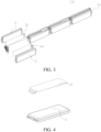
FIG. 3 is a partial exploded view of a battery module according to an embodiment of the present disclosure from one perspective; -
FIG. 4 is a schematic diagram of assembly of a second battery core and a second composite layer of a battery module according to an embodiment of the present disclosure; -
FIG. 5 is a schematic diagram of assembly of a second battery core and a second composite layer of a battery module according to an embodiment of the present disclosure; -
FIG. 6 is a partial exploded view of a battery module according to an embodiment of the present disclosure from another perspective; -
FIG. 7 is a schematic diagram of assembly of a second insulation member, a first metal member, and a first insulation layer of a battery module according to an embodiment of the present disclosure; -
FIG. 8 is a schematic diagram of assembly of a second insulation member, a second metal member, and a second insulation layer of a battery module according to an embodiment of the present disclosure; -
FIG. 9 is a schematic diagram of assembly of a body and an electrical connection piece of a battery module according to an embodiment of the present disclosure; -
FIG. 10 is a partial exploded view of a battery module according to another embodiment of the present disclosure; -
FIG. 11 is a partial exploded view of a battery module according to another embodiment of the present disclosure; -
FIG. 12 is a partial exploded view of a battery module according to another embodiment of the present disclosure; -
FIG. 13 is a partial exploded view of a battery module according to another embodiment of the present disclosure; -
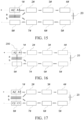
FIG. 14 is a schematic diagram of a loop formed in a battery module according to an embodiment of the present disclosure during a nail penetration test; -
FIG. 15 is a schematic diagram of a loop formed in a battery module according to an embodiment of the present disclosure during a nail penetration test; -
FIG. 16 is a schematic diagram of a loop formed in a battery module according to an embodiment of the present disclosure during a nail penetration test; -
FIG. 17 is a schematic diagram of a loop formed in a battery module according to an embodiment of the present disclosure during a nail penetration test; -
FIG. 18 is a schematic diagram of a loop formed in a battery module according to an embodiment of the present disclosure during a nail penetration test; and -
FIG. 19 is a schematic diagram of a battery module according to an embodiment of the present disclosure during a nail penetration test. -
-
battery module 100; -
first battery core 11;second battery core 12; -
protection component 20; - first
composite layer 30;first metal member 31;first insulation layer 32; - second
composite layer 40;second metal member 41;second insulation layer 42; -
second insulation member 50; -
body 61;electrical connection piece 62; -
test steel nail 200; -
battery 1;battery 2;safety structure 3. - Various exemplary embodiments of the present disclosure are described herein in detail with reference to the accompanying drawings. It should be noted that unless otherwise specified, the relative deployment, the numerical expression, and values of the components and steps described in the embodiments do not limit the scope of the present disclosure.
- In fact, the following descriptions of at least one exemplary embodiment are merely illustrative, and in no way constitute any limitation on the present disclosure and application or use of the present disclosure.
- Technologies, methods, and devices known to a person of ordinary skill in the art may not be discussed in detail, but in proper circumstances, the technologies, methods, and devices shall be regarded as a part of the specification.
- In all examples that are shown and discussed herein, any specific value should be interpreted only as an example and not as a constraint. Therefore, other examples of the exemplary embodiments may have different values.
- It should be noted that: similar reference signs or letters in the accompanying drawings indicate similar items. Therefore, once an item is defined in one accompanying drawing, the item does not need to be further discussed in the subsequent accompanying drawings.
- The present disclosure is an invention made by the inventor based on the following facts.
-
FIG. 1 and FIG. 2 show overall structural diagrams of a battery module in the related art. -
FIG. 1 shows a blade-shaped module structure in the related art. The module has positive and negative poles on a same side, and is a U-shaped series structure. As shown inFIG. 2 , the U-shaped structure has aU-shaped safety structure 3 at a tail. In this case, during a nail penetration test, a steel nail enters from abattery 1 and continues moving forward to penetrate through thebattery 2. In a process in which a single steel nail penetrates through thebattery 1, the steel nail connects positive and negative pole pieces in thebattery 1. The steel nail serves as a conductor. There is a huge current between each of the positive and negative pole pieces and the steel nail, and the huge current melts the positive and negative pole pieces around the steel nail. At a moment when the steel nail penetrates through thebattery 1 and just penetrates thebattery 2, due to existence of a potential difference between thebattery 1 and thebattery 2, arcing between the steel nail and thebattery 2 is caused. The steel nail continues penetrating thebattery 2. Since the positive and negative pole pieces of thebattery 1 are both ablated at peripheries in contact with the steel nail, contact resistance between the steel nail and the positive and negative pole pieces of thebattery 1 increases. A loop formed by thebattery 1, the steel nail, thebattery 2, another battery, and the safety structure has large resistance, which can hardly cause quick blowing of the safety structure, resulting in long duration of the arcing. The continuous arcing burns an aluminum shell through, which causes air to enter into a cavity of the module, and ignites an electrolyte in the battery, resulting in a fire. - Based on this, the inventor of the present disclosure creatively obtains the following invention after long-term researches and experiments.
- A
battery module 100 according to an embodiment of the present disclosure is described below with reference to the accompanying drawings. - As shown in
FIG. 3 to FIG. 13 , thebattery module 100 according to this embodiment of the present disclosure includes multiple battery cores, a guard assembly, and a protection component. - Specifically, the multiple battery cores are connected in series. The multiple battery cores include a first battery core group and a second battery core group oppositely arranged. The first battery core group and the second battery core group are each provided with at least one of the battery cores. The guard assembly is located between the first battery core group and the second battery core group. The guard assembly includes a
first metal member 31, a first insulation member, and asecond metal member 41 that are stacked. Thefirst metal member 31 is arranged opposite to at least one of the battery cores in the first battery core group, and thesecond metal member 41 is arranged opposite to at least one of the battery cores in the second battery core group. Theprotection component 20 is arranged between two of the battery cores adjacently arranged. Theprotection component 20 can cut off a circuit. - When a
test steel nail 200 sequentially passes through the battery core corresponding to thefirst metal member 31 in the first battery core group, thefirst metal member 31, the first insulation member, and thesecond metal member 41, a loop is formed in thebattery module 100. When thetest steel nail 200 penetrates the battery core corresponding to thesecond metal member 41 in the second battery core group, a short-circuit loop is added to thebattery module 100. - In other words, the
battery module 100 according to this embodiment of the present disclosure mainly includes multiple battery cores, a guard assembly, and a protection component. The multiple battery cores are connected in series. It should be noted that thebattery module 100 in this embodiment of the present disclosure, as a whole, may be a circuit connected in series, or may be a circuit connected in series and parallel. Optionally, the first battery core in the multiple battery cores may be electrically connected to a total positive pole of thebattery module 100, and the last battery core in the multiple battery cores may be electrically connected to a total negative pole of thebattery module 100. In other words, the multiple battery cores connected in series may form a battery core string. The first battery core in the battery core string can be electrically connected to the total positive pole, and the last battery core can be electrically connected to the total negative pole. Optionally, the total positive pole and the total negative pole of thebattery module 100 may be located on a same side. Optionally, thebattery module 100 may be substantially a U-shaped series-connection structure. - The battery core string includes a first battery core group and a second battery core group oppositely arranged. In other words, the first battery core group includes at least one battery core, and the second battery core group also includes at least one battery core. For ease of description, one battery core in the first battery core group is defined as a
first battery core 11, and one battery core in the second battery core group is defined as asecond battery core 12. Thefirst battery core 11 and thesecond battery core 12 are oppositely arranged. For example, thefirst battery core 11 and thesecond battery core 12 respectively extend along a horizontal direction, and thesecond battery core 12 is located above or below thefirst battery core 11. - It should be noted that the first battery core group includes at least one battery core, and the second battery core group includes at least one battery core. A guard assembly is arranged between the first battery core group and the second battery core group. A position of the guard assembly is described below by using examples.
- As shown in
FIG. 6 , the first battery core group includes 4 battery cores, and the second battery core group includes 4 battery cores. Thefirst battery core 11 of the first battery core group is connected to the total positive pole, and thesecond battery core 12 is connected to the total negative pole. In this case, the guard assembly is located between thefirst battery core 11 and thesecond battery core 12, and the guard assembly does not exceed thefirst battery core 11 and thesecond battery core 12. - As shown in
FIG. 10 , the first battery core group includes 4 battery cores, and the second battery core group includes 4 battery cores. For ease of description, the battery core string is divided into abattery core 1#, abattery core 2#, abattery core 3#, abattery core 4#, abattery core 5#, abattery core 6#, abattery core 7#, and abattery core 8#. The first battery core group includes thebattery core 1#, thebattery core 2#, thebattery core 3#, and thebattery core 4#. The second battery core group includes thebattery core 5#, thebattery core 6#, thebattery core 7#, and thebattery core 8#. Thebattery core 1# is connected to the total positive pole, and thebattery core 8# is connected to the total negative pole. Thebattery core 2# and thebattery core 7# are oppositely arranged. Thebattery core 3# and thebattery core 6# are oppositely arranged. Thebattery core 4# and thebattery core 5# are oppositely arranged. One side of the guard assembly is arranged opposite to thebattery core# 2, and an other side of the guard assembly is arranged opposite to thebattery core# 7. - As shown in
FIG. 11 , the first battery core group includes 4 battery cores, and the second battery core group includes 4 battery cores. For ease of description, the battery core string is divided into abattery core 1#, abattery core 2#, abattery core 3#, abattery core 4#, abattery core 5#, abattery core 6#, abattery core 7#, and abattery core 8#. The first battery core group includes thebattery core 1#, thebattery core 2#, thebattery core 3#, and thebattery core 4#. The second battery core group includes thebattery core 5#, thebattery core 6#, thebattery core 7#, and thebattery core 8#. Thebattery core 1# is connected to the total positive pole, and thebattery core 8# is connected to the total negative pole. Thebattery core 2# and thebattery core 7# are oppositely arranged. Thebattery core 3# and thebattery core 6# are oppositely arranged. Thebattery core 4# and thebattery core 5# are oppositely arranged. One side of the guard assembly is arranged opposite to thebattery core 3#, and an other side of the guard assembly is arranged opposite to thebattery core 6#. - As shown in
FIG. 12 , the first battery core group includes 4 battery cores, and the second battery core group includes 4 battery cores. For ease of description, the battery core string is divided into abattery core 1#, abattery core 2#, abattery core 3#, abattery core 4#, abattery core 5#, abattery core 6#, abattery core 7#, and abattery core 8#. The first battery core group includes thebattery core 1#, thebattery core 2#, thebattery core 3#, and thebattery core 4#. The second battery core group includes thebattery core 5#, thebattery core 6#, thebattery core 7#, and thebattery core 8#. Thebattery core 1# is connected to the total positive pole, and thebattery core 8# is connected to the total negative pole. Thebattery core 2# and thebattery core 7# are oppositely arranged. Thebattery core 3# and thebattery core 6# are oppositely arranged. Thebattery core 4# and thebattery core 5# are oppositely arranged. One side of the guard assembly is opposite to both thebattery core 2# and thebattery core 3#, and an other side of the guard assembly is opposite to both thebattery core 7# and thebattery core 6#. - As shown in
FIG. 13 , the first battery core group includes 4 battery cores, and the second battery core group includes 4 battery cores. For ease of description, the battery core string is divided into abattery core 1#, abattery core 2#, abattery core 3#, abattery core 4#, abattery core 5#, abattery core 6#, abattery core 7#, and abattery core 8#. The first battery core group includes thebattery core 1#, thebattery core 2#, thebattery core 3#, and thebattery core 4#. The second battery core group includes thebattery core 5#, thebattery core 6#, thebattery core 7#, and thebattery core 8#. Thebattery core 1# is connected to the total positive pole, and thebattery core 8# is connected to the total negative pole. Thebattery core 2# and thebattery core 7# are oppositely arranged. Thebattery core 3# and thebattery core 6# are oppositely arranged. Thebattery core 4# and thebattery core 5# are oppositely arranged. One side of the guard assembly is opposite to all of thebattery core 1#, thebattery core 2#, thebattery core 3#, and thebattery core 4#, and an other side of the guard assembly is opposite to all of thebattery core 8#, thebattery core 7#, thebattery core 6#, and thebattery core 5#. - A
first metal member 31, a first insulation member, and asecond metal member 41 may be arranged between thefirst battery core 11 and thesecond battery core 12. Thefirst metal member 31, the first insulation member, and thesecond metal member 41 are stacked. For example, thesecond battery core 12, thesecond metal member 41, the first insulation member, thefirst metal member 31, and thefirst battery core 11 are sequentially distributed from bottom to top. - The
first metal member 31 is arranged opposite to thefirst battery core 11, and thesecond metal member 41 is arranged opposite to thesecond battery core 12. It should be noted that thefirst metal member 31 may be connected to a terminal of thefirst battery core 11 or connected to a terminal of a battery core adjacent to thefirst battery core 11 or the like, and thesecond metal member 41 may also be connected to a terminal of thesecond battery core 12 or connected to a terminal of a battery core adjacent to thesecond battery core 12 or the like. Provided that a loop exists in thebattery module 100 when thetest steel nail 200 penetrates through thefirst battery core 11 and the guard assembly during a nail penetration test, when thetest steel nail 200 continues to penetrate thesecond battery core 12, a short-circuit loop is added to thebattery module 100, which falls within the protection scope of the present disclosure. - In addition, a
protection component 20 is arranged between two battery cores adjacently arranged in the multiple battery cores. Theprotection component 20 can cut off a circuit when a condition is met. For example, when a short-circuit loop is added, a resistance value of the loop decreases, and a voltage does not change. According to the Ohm's law: I=U/R, a current increases, so that theprotection component 20 can be broken, thereby cutting off the circuit of the battery core string. A fuse or a protection structure formed by a circuit structure of the circuit may be selected as theprotection component 20 according to an actual use situation. Theprotection component 20 of this structure may be configured to perform battery overcurrent protection, thereby improving use safety of thebattery module 100. For example, a fuse or an overcurrent structural member with a small cross-sectional area may be selected as theprotection component 20. Thetest steel nail 200 penetrates upward from thefirst battery core 11, first enters thefirst battery core 11, and then continues moving forward to penetrate through thefirst metal member 31 to thesecond metal member 41. In this case, the high temperature on thetest steel nail 200 melts through the first insulation member between thefirst metal member 31 and thesecond metal member 41, thereby increasing a contact area between thefirst metal member 31 and thesecond metal member 41, and forming a loop among thefirst battery core 11, thefirst metal member 31, thesecond metal member 41, theprotection component 20, and the like in advance. When thetest steel nail 200 continues moving forward to penetrate thesecond battery core 12, a short-circuit loop is added among thesecond battery core 12, thefirst metal member 31, thesecond metal member 41, theprotection component 20, and the like. According to the Ohm's law: I=U/R, a current is large, which can ensure that the fuse can quickly blow, and nail penetration does not cause a fire or explosion. The battery core in the present disclosure may be a lithium iron phosphate battery or a ternary battery such as a lithium manganate battery. - Therefore, for the
battery module 100 according to this embodiment of the present disclosure, the guard assembly is arranged between the first battery core group and the second battery core group oppositely arranged. Through cooperation between the guard assembly and the protection component, it is ensured that a circuit is cut off in time during a nail penetration test when multiple battery cores are connected in series, for example, when a number of battery cores connected in series is greater than or equal to 3, thereby avoiding arcing, fire, and combustion. - According to an embodiment of the present disclosure, as shown in
FIG. 3 ,FIG. 7, and FIG. 8 , the first insulation member includes afirst insulation layer 32 and asecond insulation layer 42, and the guard assembly includes a firstcomposite layer 30 and a secondcomposite layer 40. The firstcomposite layer 30 includes thefirst insulation layer 32 and thefirst metal member 31, and the secondcomposite layer 40 includes thesecond insulation layer 42 and thesecond metal member 41. That is, the firstcomposite layer 30 includes thefirst insulation layer 32 and thefirst metal member 31. To be specific, the firstcomposite layer 30 may include thefirst insulation layer 32 and thefirst metal member 31, or may include another structure, for example, asecond insulation member 50. When the firstcomposite layer 30 includes thefirst insulation layer 32 and thefirst metal member 31, and when an outer periphery of thefirst battery core 11 is wrapped with an insulation protection layer, an upper surface of thefirst battery core 11 is insulated from thefirst metal member 31. Similarly, when an outer periphery of thesecond battery core 12 is wrapped with an insulation protection layer, a lower surface of thesecond battery core 12 is also insulated from thesecond metal member 41. Details are not described herein again. - In some specific implementations of the present disclosure, as shown in
FIG. 7 and FIG. 8 , the guard assembly further includes asecond insulation member 50. Thesecond insulation member 50 is located between the first battery core group and thefirst metal member 31, and/or located between the second battery core group and thesecond metal member 41. When an outer surface of a battery core is provided with an insulation protection layer, the battery core is a pouch battery core. Based on this, arranging thesecond insulation member 50 between thefirst battery core 11 and thefirst metal member 31 can further enhance guarantee of insulation between thefirst battery core 11 and thefirst metal member 31, to prevent insulation between thefirst battery core 11 and thefirst metal member 31 from failing due to burrs on the outer surface of thefirst battery core 11. Similarly, arranging thesecond insulation member 50 between thesecond battery core 12 and thesecond metal member 41 can also improve reliability of insulation between thesecond battery core 12 and thesecond metal member 41. Details are not described herein again. When the outer surface of the battery core is a metal shell, thesecond insulation member 50 can be arranged to ensure that the outer surface of the battery core is insulated from the correspondingfirst metal member 31 orsecond metal member 41. - According to an embodiment of the present disclosure, the
protection component 20 is a fuse, can generate heat or even blow when the circuit is overcurrent, and has an advantage of high sensitivity. - In some specific implementations of the present disclosure, the
first metal member 31 and thesecond metal member 41 are respectively connected to terminals of corresponding battery cores. To be specific, thefirst metal member 31 is connected to a terminal of thefirst battery core 11, and thesecond metal member 41 is connected to a terminal of thesecond battery core 12. Along a direction from thefirst battery core 11 to thesecond battery core 12, a terminal of thefirst battery core 11 is arranged opposite to a terminal of thesecond battery core 12. In other words, a terminal of thefirst battery core 11 connected to thefirst metal member 31 and a terminal of thesecond battery core 12 connected to thesecond metal member 41 are oppositely arranged. - According to an embodiment of the present disclosure, the
first metal member 31 and thesecond metal member 41 are each an elongated sheet-shaped body. By adopting a sheet-shaped structure, a structural thickness along a direction from thefirst battery core 11 to thesecond battery core 12 can be reduced. An end of the sheet-shaped body along a length direction thereof is connected to a terminal of the battery core, so that a connection position on the sheet-shaped body can be prevented from hindering the nail penetration test. It should be noted that the sheet-shaped body may be connected to a left-side terminal of the battery core or may be connected to a right-side terminal of the battery core provided that a short-circuit loop is added to ensure that the fuse blows during the nail penetration test. - According to an embodiment of the present disclosure, a position at which the sheet-shaped body is connected to the battery core in the corresponding first battery core group or second battery core group is adjustable. In other words, according to a specific situation, the sheet-shaped body may be selectively connected to the left-side or right-side terminal of the battery core, or a terminal of another battery core.
- In some specific implementations of the present disclosure, as shown in
FIG. 7 to FIG. 9 , the sheet-shaped body includes abody 61 and anelectrical connection piece 62. That is, the sheet-shaped body may include a welding piece and a nail-penetrated piece. The welding piece is theelectrical connection piece 62, and the nail-penetrated piece is thebody 61. The welding piece can be connected to a terminal of a corresponding battery core. Thebody 61 is an elongated sheet-shaped body, which not only helps thetest steel nail 200 to penetrate through thebody 61, but also facilitates sandwiching thebody 61 between thefirst battery core 11 and thesecond battery core 12, so that a thickness in a direction from thefirst battery core 11 to thesecond battery core 12 can be reduced. Theelectrical connection piece 62 is located at one end of thebody 61 along a length direction. A length of theelectrical connection piece 62 is smaller than a width of thebody 61. For example, theelectrical connection piece 62 is located at a central position of thebody 61 along a width direction, to facilitate connecting theelectrical connection piece 62 to a terminal. Theelectrical connection piece 62 is a bent member, and using the bentelectrical connection piece 62 is conducive to connecting theelectrical connection piece 62 to a corresponding terminal. - According to an embodiment of the present disclosure, as shown in
FIG. 6 , a number of battery cores in the first battery core group is equal to a number of battery cores in the second battery core group. That is, a total number of battery cores is an even number. Using an even number of battery cores facilitates folding thebattery module 100 into a U-shaped structure, thereby improving a capacity of battery cores in a battery shell. When the total number of battery cores is an even number, compared with a solution with an odd number of battery cores, there is an advantage of saving space. It should be noted that the battery module of the present disclosure may also be used in a solution with an odd total number of battery cores, but has a complex structure. - The present disclosure further provides a nail penetration protection method for a
battery module 100. Thebattery module 100 is thebattery module 100 according to any one of the foregoing embodiments. The nail penetration protection method includes the following steps: - When a
test steel nail 200 penetrates through the battery core corresponding to thefirst metal member 31 in the first battery core group, thefirst metal member 31, and the first insulation member to thesecond metal member 41, a loop is formed in thebattery module 100. - When the
test steel nail 200 penetrates the battery core corresponding to thesecond metal member 41 in the second battery core group, a short-circuit loop is added to thebattery module 100. - For example, when the
test steel nail 200 penetrates through thefirst battery core 11, thefirst metal member 31, and the first insulation member to thesecond metal member 41, theprotection component 20 is located in a first loop. When thetest steel nail 200 continues to penetrate through thesecond battery core 12, theprotection component 20 is located in a second loop, and a resistance value of the second loop is smaller than a resistance value of the first loop, so that a circuit is cut off through theprotection component 20. - In other words, after a loop is added, the resistance value decreases, and a voltage does not change. According to the Ohm's law: I=U/R, a current is large, to ensure that the
protection component 20 can quickly cut off the circuit, for example, quickly blow, thereby preventing a fire or explosion during nail penetration. In addition, it should be noted that when thetest steel nail 200 penetrates through thefirst battery core 11, thefirst metal member 31, and the first insulation member to thesecond metal member 41, the fuse may possibly blow. If the fuse does not blow, when thetest steel nail 200 continues to penetrate thesecond battery core 12, blowing of the fuse can be ensured by adding a short-circuit loop. - The principle of the nail penetration protection method for a
battery module 100 according to this embodiment of the present disclosure is described below in detail with reference to specific embodiments. - As shown in
FIG. 6 , thebattery module 100 includes 8 battery cores connected in series. For ease of description, the 8 battery cores are divided into 1#, 2#, 3#, 4#, 5#, 6#, 7#, and 8#. An outer periphery of each battery core is wrapped with an insulation protection layer. That is, the battery core is a pouch battery core. A total positive pole and a total negative pole of thebattery module 100 are located on a same side of thebattery module 100. A left end of thebattery core 1# is connected to the total positive pole, and a left end of thebattery core 8# is connected to the total negative pole. Thebattery core 1# is located above thebattery core 8#, thebattery core 2# is located above thebattery core 7#, thebattery core 3# is located above thebattery core 6#, and thebattery core 4# is located above thebattery core 5#. A fuse is arranged between thebattery cores 4# and 5# as aprotection component 20. For appearance and space saving, the fuse is constructed as a U-shaped safety structure. That is, a U-shaped safety structure is arranged at a structural tail of theU-shaped battery module 100. - The
battery core# 1 is afirst battery core 11, and thebattery core# 8 is asecond battery core 12. A firstcomposite layer 30 is arranged below thebattery core 1#. The firstcomposite layer 30 includes asecond insulation member 50, afirst metal member 31, and afirst insulation layer 32 from bottom to top. A secondcomposite layer 40 is arranged below the firstcomposite layer 30. The secondcomposite layer 40 includes asecond insulation layer 42, asecond metal member 41, and asecond insulation member 50 from bottom to top. Anelectrical connection piece 62 of thefirst metal member 31 is connected to a terminal on a side of thebattery core 1# close to thebattery core 2#, and anelectrical connection piece 62 of thesecond metal member 41 is connected to a terminal on a side of thebattery core 8# close to thebattery core 7#. For ease of description, the firstcomposite layer 30 including thesecond insulation member 50, thefirst metal member 31, and thefirst insulation layer 32 is defined as a nail-penetrated sheet a, and the secondcomposite layer 40 including thesecond insulation layer 42, thesecond metal member 41, and thesecond insulation member 50 is defined as a nail-penetrated sheet b. - During a nail penetration test, a steel nail penetrates the
battery core 1# from a middle thereof. Using the middle of thebattery core 1# as a dividing line, a part of thebattery core 1# close to thebattery core 2# is A1, and a part thereof close to the total positive pole is A2. Similarly, using a middle of thebattery core 8# as a dividing line, a part of thebattery core 8# close to thebattery core 2# is C1, and a part thereof close to the total positive pole is C2. - When the steel nail penetrates through the
battery core 1# from top to bottom, and continues moving downward to penetrate through thefirst metal member 31 to thesecond metal member 41, the high temperature on the steel nail melts through thefirst insulation layer 32 and thesecond insulation layer 42 between thefirst metal member 31 and thesecond metal member 41. In this case, a contact area between thefirst metal member 31 and thesecond metal member 41 increases. In this case, two loops are formed, which are specifically aloop 1 shown inFIG. 14 : a-A1-2#...-7#-right-side terminal of 8#-b-a; and aloop 2 shown inFIG. 15 : a-right-side terminal ofbattery core 1#-2#...right-side terminal of 8#-b-a, which is equivalent to externally short-circuiting thebattery core 2# and thebattery core 7#. In this case, there are two cases: the fuse blows or the fuse does not blow. For example, as shown inFIG. 19 , using afirst battery core 11 as an example for description, a left-side terminal of thefirst battery core 11 is A, and a right-side terminal thereof is B. A is aluminum foil, and B is copper foil, and there is a membrane for insulation therebetween. When thetest steel nail 200 penetrates through thefirst battery core 11, A and B are connected by the steel nail. Therefore, there is a loop in which a current passes through a to B, then passes through the steel nail to B, and then flows to thebattery core 2#. - If the fuse does not blow, when the steel nail continues moving downward to penetrate through the
battery core 8#, three loops are formed, which are specifically aloop 1 shown inFIG. 16 : a-A1-2#...7#-right-side terminal of 8#-b-a; aloop 2 shown inFIG. 17 : a-right-side terminal of 1#-2#...7#-right-side terminal of 8#-b-a; and aloop 3 shown inFIG. 18 : a-right-side terminal of 1#-2#...7#-C1-b-a, where if theloop 2 causes the fuse to break, theloop 3 does not exist. - In view of the above, when the steel nail penetrates the
battery core 8#, a short-circuit loop is added to the battery core string, the resistance value of the loop decreases, and a voltage does not change. According to the Ohm's law: I=U/R, a current is large, to ensure that the fuse can quickly blow, thereby preventing a fire or explosion during nail penetration. - In conclusion, according to the
battery module 100 in the embodiments of the present disclosure, by arranging the guard assembly between two battery cores oppositely arranged, during a nail penetration test, in a case that thesteel nail 200 passes through a battery core, and the fuse does not blow, the fuse can be ensured to blow by adding a short-circuit loop when thesteel nail 200 continues to penetrate another battery core, thereby greatly improving safety performance of thebattery module 100. - The present disclosure further provides a vehicle, including the
battery module 100 according to any one of the foregoing embodiments. Because thebattery module 100 avoids severe arcing, fire, and combustion during a nail penetration test, and has high safety performance, the vehicle of the present disclosure also has the same advantages. Details are not described herein again. - Although some specific embodiments of the present disclosure have been described in detail by way of examples, a person skilled in the art should understand that the foregoing examples are only for description and are not intended to limit the scope of the present disclosure. A person skilled in the art should appreciate that modifications may be made to the foregoing embodiments without departing from the scope and spirit of the present disclosure. The scope of the present disclosure is limited only by the appended claims.
Claims (10)
- A battery module, comprising:a plurality of battery cores, connected in series and comprising a first battery core group and a second battery core group oppositely arranged, the first battery core group and the second battery core group being each provided with at least one of the battery cores;a guard assembly, located between the first battery core group and the second battery core group, and comprising a first metal member, a first insulation member, and a second metal member that are stacked, wherein the first metal member is arranged opposite to at least one of the battery cores in the first battery core group, and the second metal member is arranged opposite to at least one of the battery cores in the second battery core group; anda protection component, arranged between two of the battery cores adjacently arranged, and configured to cut off a circuit,wherein when a test steel nail sequentially passes through the battery core corresponding to the first metal member in the first battery core group, the first metal member, the first insulation member, and the second metal member, a loop is formed in the battery module; andwhen the test steel nail penetrates the battery core corresponding to the second metal member in the second battery core group, a short-circuit loop is added to the battery module.
- The battery module according to claim 1, wherein the first insulation member comprises a first insulation layer and a second insulation layer, and the guard assembly comprises a first composite layer and a second composite layer, the first composite layer comprising the first insulation layer and the first metal member, and the second composite layer comprising the second insulation layer and the second metal member.
- The battery module according to claim 1 or 2, wherein the guard assembly further comprises:
a second insulation member, located between the first battery core group and the first metal member, and/or located between the second battery core group and the second metal member. - The battery module according to any one of claims 1 to 3, wherein the protection component is a fuse.
- The battery module according to any one of claims 1 to 3, wherein the first metal member and the second metal member are each an elongated sheet-shaped body, an end of the sheet-shaped body along a length direction thereof being connected to a terminal of the battery core.
- The battery module according to any one of claims 1 to 3, wherein a position at which the sheet-shaped body is connected to the battery core in the corresponding first battery core group or second battery core group is adjustable.
- The battery module according to any one of claims 1 to 3, wherein the sheet-shaped body comprises a body and an electrical connection piece, the body being in an elongated shape, and the electrical connection piece being located at an end of the body along a length direction, a length of the electrical connection piece being less than a width of the body, and the electrical connection piece being a bent member.
- The battery module according to any one of claims 1 to 3, wherein a number of the battery cores in the first battery core group is equal to a number of the battery cores in the second battery core group.
- A nail penetration protection method for a battery module, the battery module being the battery module according to any one of claims 1 to 8, and the nail penetration protection method comprising the following steps:forming a loop in the battery module when a test steel nail sequentially penetrates through the battery core corresponding to the first metal member in the first battery core group, the first metal member, and the first insulation member to the second metal member; andadding a short-circuit loop to the battery module when the test steel nail penetrates the battery core corresponding to the second metal member in the second battery core group.
- A vehicle, comprising the battery module according to any one of claims 1 to 8.
Applications Claiming Priority (2)
| Application Number | Priority Date | Filing Date | Title |
|---|---|---|---|
| CN202210473891.7A CN117013211A (en) | 2022-04-29 | 2022-04-29 | Battery module, needling protection method of battery module and vehicle |
| PCT/CN2023/076851 WO2023207270A1 (en) | 2022-04-29 | 2023-02-17 | Battery module, nail penetration protection method for battery module, and vehicle |
Publications (2)
| Publication Number | Publication Date |
|---|---|
| EP4518014A1 true EP4518014A1 (en) | 2025-03-05 |
| EP4518014A4 EP4518014A4 (en) | 2025-08-20 |
Family
ID=88517220
Family Applications (1)
| Application Number | Title | Priority Date | Filing Date |
|---|---|---|---|
| EP23794706.4A Pending EP4518014A4 (en) | 2022-04-29 | 2023-02-17 | BATTERY MODULE, NAIL PENETRATION PROTECTION METHOD FOR BATTERY MODULE AND VEHICLE |
Country Status (6)
| Country | Link |
|---|---|
| US (1) | US20250030138A1 (en) |
| EP (1) | EP4518014A4 (en) |
| JP (1) | JP7793814B2 (en) |
| KR (1) | KR20240155325A (en) |
| CN (1) | CN117013211A (en) |
| WO (1) | WO2023207270A1 (en) |
Families Citing this family (1)
| Publication number | Priority date | Publication date | Assignee | Title |
|---|---|---|---|---|
| CN117878514A (en) * | 2023-12-08 | 2024-04-12 | 华为数字能源技术有限公司 | Battery modules, battery packs and energy storage systems |
Family Cites Families (10)
| Publication number | Priority date | Publication date | Assignee | Title |
|---|---|---|---|---|
| JP5285961B2 (en) * | 2008-05-27 | 2013-09-11 | 株式会社ケーヒン | Battery control device for battery pack |
| US8883332B2 (en) | 2011-12-09 | 2014-11-11 | Samsung Sdi Co., Ltd. | Rechargeable secondary battery |
| WO2014109041A1 (en) | 2013-01-11 | 2014-07-17 | 株式会社 日立製作所 | Cell module and cell system using same |
| CN104347892B (en) * | 2013-08-02 | 2017-04-19 | 万向一二三股份公司 | Lithium battery |
| KR101816974B1 (en) | 2014-11-17 | 2018-02-21 | 주식회사 엘지화학 | Cooling plate for secondary battery and secondary battery module comprising the same |
| EP3951906A4 (en) * | 2019-03-29 | 2023-08-16 | Mitsui Chemicals, Inc. | Lithium ion battery stack |
| KR20210090477A (en) * | 2020-01-10 | 2021-07-20 | 에스케이이노베이션 주식회사 | Battery module with improved stability |
| CN115004455B (en) * | 2020-01-31 | 2025-09-02 | Sk新能源株式会社 | battery module |
| CN212517351U (en) * | 2020-07-23 | 2021-02-09 | 中航锂电(洛阳)有限公司 | Battery modules and battery packs |
| CN214477798U (en) * | 2021-03-31 | 2021-10-22 | 比亚迪股份有限公司 | Battery, battery pack and vehicle |
-
2022
- 2022-04-29 CN CN202210473891.7A patent/CN117013211A/en active Pending
-
2023
- 2023-02-17 KR KR1020247032740A patent/KR20240155325A/en active Pending
- 2023-02-17 JP JP2024561967A patent/JP7793814B2/en active Active
- 2023-02-17 EP EP23794706.4A patent/EP4518014A4/en active Pending
- 2023-02-17 WO PCT/CN2023/076851 patent/WO2023207270A1/en not_active Ceased
-
2024
- 2024-10-09 US US18/910,739 patent/US20250030138A1/en active Pending
Also Published As
| Publication number | Publication date |
|---|---|
| WO2023207270A1 (en) | 2023-11-02 |
| CN117013211A (en) | 2023-11-07 |
| JP2025514787A (en) | 2025-05-09 |
| EP4518014A4 (en) | 2025-08-20 |
| JP7793814B2 (en) | 2026-01-05 |
| US20250030138A1 (en) | 2025-01-23 |
| KR20240155325A (en) | 2024-10-28 |
Similar Documents
| Publication | Publication Date | Title |
|---|---|---|
| US10804526B2 (en) | Electrode member, electrode assembly and rechargeable battery | |
| EP2612387B1 (en) | Current collecting terminal for electrochemical cells | |
| KR102425797B1 (en) | Rechargeable secondary battery | |
| US9225000B2 (en) | Current collecting terminal with PTC layer for electrochemical cells | |
| JP4084926B2 (en) | Fracture control mechanism for electrochemical cells | |
| EP2876708B1 (en) | Rechargeable battery having fuse | |
| US20170187025A1 (en) | Secondary battery | |
| CN103326061B (en) | Lithium rechargeable battery | |
| US9203117B2 (en) | Rechargeable secondary battery | |
| US20250030138A1 (en) | Battery module, nail penetration method for battery module, and vehicle | |
| US20150044526A1 (en) | Rechargeable battery | |
| US20250125506A1 (en) | Connector | |
| US20170271641A1 (en) | Secondary battery | |
| CN213483695U (en) | Insurance structure, battery package and vehicle | |
| EP2710654B1 (en) | Connection assembly for cells in a battery | |
| CN112234296A (en) | Cells and battery modules | |
| JPH1167279A (en) | Battery | |
| KR101715964B1 (en) | Rechargeable secondary battery | |
| JP2025514787A5 (en) | ||
| EP3279982B1 (en) | Current collector with an improved security behavior and battery cell comprising the same | |
| CN110911628B (en) | Power battery | |
| CN208819997U (en) | Secondary battery | |
| EP4156216A1 (en) | Electrical storage element | |
| CN207504024U (en) | A kind of column lithium ion battery group | |
| CN218101362U (en) | Cylindrical battery cell |
Legal Events
| Date | Code | Title | Description |
|---|---|---|---|
| STAA | Information on the status of an ep patent application or granted ep patent |
Free format text: STATUS: THE INTERNATIONAL PUBLICATION HAS BEEN MADE |
|
| PUAI | Public reference made under article 153(3) epc to a published international application that has entered the european phase |
Free format text: ORIGINAL CODE: 0009012 |
|
| STAA | Information on the status of an ep patent application or granted ep patent |
Free format text: STATUS: REQUEST FOR EXAMINATION WAS MADE |
|
| 17P | Request for examination filed |
Effective date: 20241128 |
|
| AK | Designated contracting states |
Kind code of ref document: A1 Designated state(s): AL AT BE BG CH CY CZ DE DK EE ES FI FR GB GR HR HU IE IS IT LI LT LU LV MC ME MK MT NL NO PL PT RO RS SE SI SK SM TR |
|
| DAV | Request for validation of the european patent (deleted) | ||
| DAX | Request for extension of the european patent (deleted) | ||
| A4 | Supplementary search report drawn up and despatched |
Effective date: 20250721 |
|
| RIC1 | Information provided on ipc code assigned before grant |
Ipc: H01M 50/583 20210101AFI20250715BHEP Ipc: H01M 50/593 20210101ALI20250715BHEP Ipc: H01M 50/209 20210101ALI20250715BHEP Ipc: H01M 50/211 20210101ALI20250715BHEP Ipc: H01M 50/249 20210101ALI20250715BHEP Ipc: H01M 50/51 20210101ALI20250715BHEP Ipc: H01M 50/258 20210101ALI20250715BHEP Ipc: H01M 50/572 20210101ALI20250715BHEP |