EP4517997A2 - Separator für elektrochemische vorrichtung und elektrochemische vorrichtung damit - Google Patents
Separator für elektrochemische vorrichtung und elektrochemische vorrichtung damit Download PDFInfo
- Publication number
- EP4517997A2 EP4517997A2 EP24781357.9A EP24781357A EP4517997A2 EP 4517997 A2 EP4517997 A2 EP 4517997A2 EP 24781357 A EP24781357 A EP 24781357A EP 4517997 A2 EP4517997 A2 EP 4517997A2
- Authority
- EP
- European Patent Office
- Prior art keywords
- coating layer
- separator
- polymer
- porous
- electrochemical device
- Prior art date
- Legal status (The legal status is an assumption and is not a legal conclusion. Google has not performed a legal analysis and makes no representation as to the accuracy of the status listed.)
- Pending
Links
Images
Classifications
-
- H—ELECTRICITY
- H01—ELECTRIC ELEMENTS
- H01M—PROCESSES OR MEANS, e.g. BATTERIES, FOR THE DIRECT CONVERSION OF CHEMICAL ENERGY INTO ELECTRICAL ENERGY
- H01M10/00—Secondary cells; Manufacture thereof
- H01M10/05—Accumulators with non-aqueous electrolyte
- H01M10/052—Li-accumulators
-
- H—ELECTRICITY
- H01—ELECTRIC ELEMENTS
- H01M—PROCESSES OR MEANS, e.g. BATTERIES, FOR THE DIRECT CONVERSION OF CHEMICAL ENERGY INTO ELECTRICAL ENERGY
- H01M50/00—Constructional details or processes of manufacture of the non-active parts of electrochemical cells other than fuel cells, e.g. hybrid cells
- H01M50/40—Separators; Membranes; Diaphragms; Spacing elements inside cells
- H01M50/403—Manufacturing processes of separators, membranes or diaphragms
-
- H—ELECTRICITY
- H01—ELECTRIC ELEMENTS
- H01M—PROCESSES OR MEANS, e.g. BATTERIES, FOR THE DIRECT CONVERSION OF CHEMICAL ENERGY INTO ELECTRICAL ENERGY
- H01M50/00—Constructional details or processes of manufacture of the non-active parts of electrochemical cells other than fuel cells, e.g. hybrid cells
- H01M50/40—Separators; Membranes; Diaphragms; Spacing elements inside cells
- H01M50/409—Separators, membranes or diaphragms characterised by the material
- H01M50/411—Organic material
- H01M50/414—Synthetic resins, e.g. thermoplastics or thermosetting resins
- H01M50/417—Polyolefins
-
- H—ELECTRICITY
- H01—ELECTRIC ELEMENTS
- H01M—PROCESSES OR MEANS, e.g. BATTERIES, FOR THE DIRECT CONVERSION OF CHEMICAL ENERGY INTO ELECTRICAL ENERGY
- H01M50/00—Constructional details or processes of manufacture of the non-active parts of electrochemical cells other than fuel cells, e.g. hybrid cells
- H01M50/40—Separators; Membranes; Diaphragms; Spacing elements inside cells
- H01M50/409—Separators, membranes or diaphragms characterised by the material
- H01M50/411—Organic material
- H01M50/414—Synthetic resins, e.g. thermoplastics or thermosetting resins
- H01M50/42—Acrylic resins
-
- H—ELECTRICITY
- H01—ELECTRIC ELEMENTS
- H01M—PROCESSES OR MEANS, e.g. BATTERIES, FOR THE DIRECT CONVERSION OF CHEMICAL ENERGY INTO ELECTRICAL ENERGY
- H01M50/00—Constructional details or processes of manufacture of the non-active parts of electrochemical cells other than fuel cells, e.g. hybrid cells
- H01M50/40—Separators; Membranes; Diaphragms; Spacing elements inside cells
- H01M50/409—Separators, membranes or diaphragms characterised by the material
- H01M50/431—Inorganic material
-
- H—ELECTRICITY
- H01—ELECTRIC ELEMENTS
- H01M—PROCESSES OR MEANS, e.g. BATTERIES, FOR THE DIRECT CONVERSION OF CHEMICAL ENERGY INTO ELECTRICAL ENERGY
- H01M50/00—Constructional details or processes of manufacture of the non-active parts of electrochemical cells other than fuel cells, e.g. hybrid cells
- H01M50/40—Separators; Membranes; Diaphragms; Spacing elements inside cells
- H01M50/409—Separators, membranes or diaphragms characterised by the material
- H01M50/443—Particulate material
-
- H—ELECTRICITY
- H01—ELECTRIC ELEMENTS
- H01M—PROCESSES OR MEANS, e.g. BATTERIES, FOR THE DIRECT CONVERSION OF CHEMICAL ENERGY INTO ELECTRICAL ENERGY
- H01M50/00—Constructional details or processes of manufacture of the non-active parts of electrochemical cells other than fuel cells, e.g. hybrid cells
- H01M50/40—Separators; Membranes; Diaphragms; Spacing elements inside cells
- H01M50/409—Separators, membranes or diaphragms characterised by the material
- H01M50/446—Composite material consisting of a mixture of organic and inorganic materials
-
- H—ELECTRICITY
- H01—ELECTRIC ELEMENTS
- H01M—PROCESSES OR MEANS, e.g. BATTERIES, FOR THE DIRECT CONVERSION OF CHEMICAL ENERGY INTO ELECTRICAL ENERGY
- H01M50/00—Constructional details or processes of manufacture of the non-active parts of electrochemical cells other than fuel cells, e.g. hybrid cells
- H01M50/40—Separators; Membranes; Diaphragms; Spacing elements inside cells
- H01M50/409—Separators, membranes or diaphragms characterised by the material
- H01M50/449—Separators, membranes or diaphragms characterised by the material having a layered structure
- H01M50/451—Separators, membranes or diaphragms characterised by the material having a layered structure comprising layers of only organic material and layers containing inorganic material
-
- H—ELECTRICITY
- H01—ELECTRIC ELEMENTS
- H01M—PROCESSES OR MEANS, e.g. BATTERIES, FOR THE DIRECT CONVERSION OF CHEMICAL ENERGY INTO ELECTRICAL ENERGY
- H01M50/00—Constructional details or processes of manufacture of the non-active parts of electrochemical cells other than fuel cells, e.g. hybrid cells
- H01M50/40—Separators; Membranes; Diaphragms; Spacing elements inside cells
- H01M50/409—Separators, membranes or diaphragms characterised by the material
- H01M50/449—Separators, membranes or diaphragms characterised by the material having a layered structure
- H01M50/457—Separators, membranes or diaphragms characterised by the material having a layered structure comprising three or more layers
-
- H—ELECTRICITY
- H01—ELECTRIC ELEMENTS
- H01M—PROCESSES OR MEANS, e.g. BATTERIES, FOR THE DIRECT CONVERSION OF CHEMICAL ENERGY INTO ELECTRICAL ENERGY
- H01M50/00—Constructional details or processes of manufacture of the non-active parts of electrochemical cells other than fuel cells, e.g. hybrid cells
- H01M50/40—Separators; Membranes; Diaphragms; Spacing elements inside cells
- H01M50/489—Separators, membranes, diaphragms or spacing elements inside the cells, characterised by their physical properties, e.g. swelling degree, hydrophilicity or shut down properties
-
- Y—GENERAL TAGGING OF NEW TECHNOLOGICAL DEVELOPMENTS; GENERAL TAGGING OF CROSS-SECTIONAL TECHNOLOGIES SPANNING OVER SEVERAL SECTIONS OF THE IPC; TECHNICAL SUBJECTS COVERED BY FORMER USPC CROSS-REFERENCE ART COLLECTIONS [XRACs] AND DIGESTS
- Y02—TECHNOLOGIES OR APPLICATIONS FOR MITIGATION OR ADAPTATION AGAINST CLIMATE CHANGE
- Y02E—REDUCTION OF GREENHOUSE GAS [GHG] EMISSIONS, RELATED TO ENERGY GENERATION, TRANSMISSION OR DISTRIBUTION
- Y02E60/00—Enabling technologies; Technologies with a potential or indirect contribution to GHG emissions mitigation
- Y02E60/10—Energy storage using batteries
-
- Y—GENERAL TAGGING OF NEW TECHNOLOGICAL DEVELOPMENTS; GENERAL TAGGING OF CROSS-SECTIONAL TECHNOLOGIES SPANNING OVER SEVERAL SECTIONS OF THE IPC; TECHNICAL SUBJECTS COVERED BY FORMER USPC CROSS-REFERENCE ART COLLECTIONS [XRACs] AND DIGESTS
- Y02—TECHNOLOGIES OR APPLICATIONS FOR MITIGATION OR ADAPTATION AGAINST CLIMATE CHANGE
- Y02P—CLIMATE CHANGE MITIGATION TECHNOLOGIES IN THE PRODUCTION OR PROCESSING OF GOODS
- Y02P70/00—Climate change mitigation technologies in the production process for final industrial or consumer products
- Y02P70/50—Manufacturing or production processes characterised by the final manufactured product
Definitions
- the present disclosure relates to a separator for an electrochemical device and an electrochemical device including the separator.
- Electrochemical devices convert chemical energy into electric energy using electrochemical reactions, and in recent years, lithium secondary batteries have been widely used in view of high energy density and voltage, long cycle life, and applicability in various fields.
- a lithium secondary battery may include an electrode assembly fabricated using a positive electrode, a negative electrode, and a separator disposed between the positive and negative electrodes, and may be manufactured by accommodating the electrode assembly in a case with an electrolyte solution.
- the present disclosure provides a separator for an electrochemical device that exhibits a reduced dimensional change rate in a high temperature wet state, a method of manufacturing the separator, and an electrochemical device including the separator.
- a separator for an electrochemical device including: a porous polymer substrate; and a porous coating layer formed on at least one surface of the porous polymer substrate, the porous coating layer includes inorganic particles and a polymer binder, the inorganic particles have, on surfaces thereof, a coating layer of a polymer including an amine group, and at least a portion of the polymer binder is crosslinked with the polymer including the amine group.
- the polymer including the amine group is dopamine or a derivative thereof.
- a thickness of the coating layer is about 2 nm to 20 nm.
- the polymer binder includes one or more selected from the group consisting of dextrin, polyetheretherketone, polyethersulfone, and polyacrylamide.
- the polymer binder includes a (co)polymer of a monomer selected from the group consisting of acrylate, acrylic acid, maleic acid, itaconic acid, methacrylic acid, and carboxyethyl acrylate.
- about 60 wt% to 80 wt% of the polymer binder is crosslinked with the polymer including the amine group.
- a loading amount of the porous coating layer for a unit area of the porous polymer substrate is about 5.5 g/m 2 to 8 g/m 2 .
- the porous coating layer includes the inorganic particles in a content of about 90 wt% to 95 wt% based on a total weight of the porous coating layer.
- the separator further includes a second polymer coating layer formed on a surface of the porous coating layer, and the second polymer coating layer includes the polymer including the amine group.
- At least a portion of the polymer including the amine group in the second polymer coating layer is crosslinked with the polymer binder of the porous coating layer.
- the second polymer coating layer further includes dextrin.
- an electrochemical device including: a positive electrode; a negative electrode; and a separator disposed between the positive electrode and the negative electrode, and the separator is the separator for the electrochemical device described above.
- the electrochemical device may be a lithium secondary battery.
- the separator for the electrochemical device provides an improved dimensional stability in the wet state where the separator is impregnated with the electrolyte solution.
- the separator exhibits a thermal shrinkage rate of less than about 10 % in the TD direction under a high temperature condition of about 130 °C or higher, and therefore, the exposure of an electrode caused from the thermal shrinkage of the separator may be prevented.
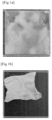
- Fig. 1a and 1b are images of separators of Example 1 and Comparative Example 1, respectively, which are each inserted into a pouch with an electrolyte solution, stored in a 135 °C convection oven for 30 minutes, and then, taken out from the oven to check the appearance of the separator according to experimental examples.
- an “electrochemical device” indicates, for example, a primary battery, a secondary battery, and a supercapacitor.
- wet state refers to the state where a separator is impregnated with at least a portion of an electrolyte solution.
- a separator may include a porous coating layer, which includes a polymer binder and inorganic particles, on at least one surface of a porous substrate.
- the inorganic particles are connected together by the polymer binder to form interstitial volumes, and lithium ions may move through the interstitial volumes.
- the polymer binder may impart an adhesion to the porous coating layer such that the porous coating layer may adhere to each of the porous substrate and an electrode.
- the porous coating layer including the polymer binder and the inorganic particles may prevent the thermal shrinkage of the porous polymer substrate, and the separator including the porous coating layer exhibits the excellent dimensional stability in the dry state where no electrolyte solution exists.
- the separator in the wet state where the separator is impregnated with the electrolyte solution, the polymer binder swells by the electrolyte solution, or the separator is exposed to a temperature of about 130 °C or higher by the operation of the lithium secondary battery including the separator, and as a result, the adhesion of the polymer binder is degraded.
- the adhesion of the porous coating layer decreases, and the separator shrinks significantly.
- the present disclosure provides a separator, which ensures the dimensional stability under the conditions of the high temperature and the wet state while maintaining the relatively low content of the polymer binder in the porous coating layer.
- An embodiment of the present disclosure provides a separator for an electrochemical device, which includes a porous polymer substrate and a porous coating layer formed on at least one surface of the porous polymer substrate.
- the porous coating layer includes inorganic particles and a polymer binder, the inorganic particles have a coating layer of a polymer including an amine group on their surfaces, and at least a portion of the polymer binder is crosslinked with the polymer including the amine group.
- the porous polymer substrate uses a material physically and chemically stable for the electrolyte solution, which is an organic solvent.
- the porous polymer substrate includes polyolefins such as polyethylene, polypropylene, and polybutylene, and resins such as polyvinyl chloride, polyethylene terephthalate, polycycloolefin, polyethersulfone, polyamide, polyimide, polyimidamide, nylon, polytetrafluoroethylene, and copolymers or mixtures thereof, but is not limited thereto.
- a polyolefin-based resin may be used.
- the polyolefin-based resin may be processed to have a relatively thin thicknesses, and may easily be coated with a coating slurry, which is suitable for manufacturing an electrochemical device having the higher energy density.
- the porous polymer substrate has a monolayer or multilayer structure.
- the porous polymer substrate may include two or more polymer resin layers having different melting points (Tm), to provide the shutdown function in the event of the high temperature runaway of a battery.
- Tm melting points
- the porous polymer substrate includes a polypropylene layer having a relatively high melting point and a polyethylene layer having a relatively low melting point.
- the porous polymer substrate may have a three-layer structure in which polypropylene, polyethylene, and polypropylene are laminated in this order.
- the polyethylene layer may shut down the pores by melting as the temperature of a battery rises to a predetermined temperature or more, thereby preventing the thermal runaway of the battery.
- the thickness of the porous polymer substrate is about 1 ⁇ m to 100 ⁇ m.
- the thickness of the porous polymer substrate may be about 10 ⁇ m to 90 ⁇ m, about 20 ⁇ m to 80 ⁇ m, about 30 ⁇ m to 70 ⁇ m, or about 40 ⁇ m to 60 ⁇ m.
- the thickness of the polymer substrate may be about 1 ⁇ m to 30 ⁇ m.
- the thickness of the polymer substrate may be about 5 ⁇ m to 15 ⁇ m, or about 8 ⁇ m to 13 ⁇ m.
- the porous polymer substrate includes pores having an average diameter of about 0.01 ⁇ m to 1 ⁇ m.
- the size of the pores included in the porous polymer substrate may be about 0.01 ⁇ m to 0.09 ⁇ m, about 0.02 ⁇ m to 0.08 ⁇ m, about 0.03 ⁇ m to 0.07 ⁇ m, or about 0.04 ⁇ m to 0.06 ⁇ m. Further, the size of the pores may be about 0.02 ⁇ m to 0.06 ⁇ m.
- the porous polymer substrate has the air permeability of about 10 s/100 cc to 100 s/100 cc.
- the air permeability of the porous polymer substrate may be about 10 s/100 cc to 90 s/100 cc, about 20 s/100 cc to 80 s/100 cc, about 30 s/100 cc to 70 s/100 cc, or about 40 s/100 cc to 60 s/100 cc.
- the air permeability of the porous polymer substrate may be about 50 s/100 cc to 70 s/100 cc.
- the manufactured separator may provide the air permeability in the range suitable for ensuring the power output and the cycle characteristics of the electrochemical device.
- the porous polymer substrate may have the porosity of about 10 vol% to 60 vol%.
- the porosity of the porous polymer substrate may be about 15 vol% to 55 vol%, about 20 vol% to 50 vol%, about 25 vol% to 45 vol%, or about 30 vol% to 40 vol%.
- the porosity of the porous polymer substrate may be about 30 vol% to 50 vol%.
- the manufactured separator may provide the ion conductivity in the range suitable for ensuring the power output and the cycle characteristics of the electrochemical device.
- the porosity indicates the ratio of the volume of the pores to the total volume of the porous polymer substrate.
- the porosity may be measured by any method well-known in the art of the present disclosure.
- the porosity may be measured by the Brunauer Emmett Teller (BET) method using an adsorption of nitrogen gas, a capillary flow porometer, or a water or mercury permeation method.
- BET Brunauer Emmett Teller
- the porous coating layer is formed on at least one surface of the porous polymer substrate, and includes inorganic particles and a polymer binder.
- the porous coating layer is formed in the manner that at least one surface of the porous polymer substrate is coated with a coating slurry including the inorganic particles, the polymer binder, and a dispersant.
- the separator may be manufactured by coating at least one surface of the porous polymer substrate with the coating slurry, and then, drying the slurry to remove the dispersant.
- the porous coating layer includes the interstitial volumes among the inorganic particles connected by the polymer binder so as to allow the passage of lithium ions therethrough, and adheres to the porous polymer substrate so as to prevent the thermal shrinkage of the porous polymer substrate.
- the coating slurry includes the dispersant to dissolve or disperse at least a portion of the polymer binder and disperse the inorganic particles.
- the coating slurry is a slurry in which the polymer binder and the inorganic particles are uniformly dispersed by adjusting the type and the content of the dispersant.
- the dispersant is one selected from the group consisting of water, ethanol, acetone, isopropyl alcohol (IPA), dimethylacetamide (DMAc), dimethylformamide (DMF), N-methyl-2-pyrrolidone (NMP), acetonitrile, and combinations thereof.
- the coating slurry has a viscosity of about 100 cps to 1,000 cps.
- the viscosity of the coating slurry may be about 200 cps to 900 cps, about 300 cps to 800 cps, about 400 cps to 700 cps, or about 500 cps to 600 cps.
- the viscosity of the coating slurry may be about 300 cps to 800 cps.
- the porous coating layer may be formed by continuously coating the porous polymer substrate with the coating slurry.
- the coating slurry further includes additives such as a dispersant, a surfactant, a defoamer, and a flame retardant, to enhance the dispersibility and the flame retardancy and improve the uniformity of the formed porous coating layer.
- the dispersant may include one or more selected from the group consisting of oil-soluble polyamine, an oil-soluble amine compound, fatty acids, fatty alcohols, sorbitan fatty acid ester, tannic acid, and pyrogallic acid.
- this type of dispersant is used, the stability of the coating slurry may be improved, and the uniformity of the porous coating layer formed by the coating slurry may be ensured.
- the dispersant included in the coating slurry is removed through a drying or a heating after the porous coating layer is formed.
- the porous coating layer includes about 5 ppm or less of the dispersant.
- the porous coating layer may be formed with an acrylic-based polymer binder, a copolymer binder, and inorganic particles.
- a plurality of pores is formed in the surface and the inside of the porous coating layer. The pores include the interstitial volumes formed among the inorganic particles, and has the structure of the three-dimensional network through which a fluid can pass.
- the thickness of the porous coating layer is about 0.1 ⁇ m to 10 ⁇ m.
- the thickness of the porous coating layer may be about 0.5 ⁇ m to 9.5 ⁇ m, about 1.0 ⁇ m to 9.0 ⁇ m, about 1.5 ⁇ m to 8.5 ⁇ m, about 2.0 ⁇ m to 8.0 ⁇ m, about 2.5 ⁇ m to 7.5 ⁇ m, about 3.0 ⁇ m to 7.0 ⁇ m, about 3.5 ⁇ m to 6.5 ⁇ m, about 4.0 ⁇ m to 6.0 ⁇ m, or about 4.5 ⁇ m to 5.5 ⁇ m.
- the thickness of the porous coating layer may be about 0.5 ⁇ m to 5 ⁇ m.
- the thickness of the porous coating layer may be about 0.5 ⁇ m to 2 ⁇ m.
- the porous coating layer includes inorganic particles having a coating layer of a polymer including an amine group on the surfaces thereof, and a polymer binder, and at least a portion of the polymer binder is crosslinked with the polymer including the amine group.
- the polymer binder may include two or more different types of polymer binders, at least one of the polymer binders may be crosslinked with the polymer including the amine group.
- the polymer binder, which is crosslinked with the polymer including the amine group forms a physical or chemical bond with the polymer including the amine group.
- the polymer binder, which is crosslinked with the polymer including the amine group may be thermally crosslinked via the amine group.
- the polymer binder is bonded with one or more inorganic particles through the crosslinking with the coating layer of the inorganic particles, thereby forming the interstitial volumes.
- the polymer binder forms and maintains a stronger bond with the inorganic particles having the coating layer, as compared to the inorganic particles having no coating layer, and the porous coating layer including the polymer binder may exhibit the reduced thermal shrinkage rate in the high temperature wet state.
- electrochemically stable inorganic particles are used.
- the inorganic particles are not particularly limited as long as oxidation and/or reduction reactions do not occur in an operation voltage range of the electrochemical device (e.g., 0 V to 5 V based on Li/Li + ).
- the inorganic particles contribute to increasing the dissociation of electrolyte salt, for example, lithium salt in the liquid electrolyte, which improves the ion conductivity of the electrolyte solution.
- the inorganic particles may include inorganic particles with the high dielectric constant of 5 or more, for example, 10 or more.
- Non-limiting examples of the inorganic particles with the dielectric constant of 5 or more include BaTiO 3 , Pb(Zr,Ti)O 3 (PZT), Pb 1-x La x Zr 1-y Ti y O 3 (PLZT, 0 ⁇ x ⁇ 1, 0 ⁇ y ⁇ 1), Pb(Mg 1/3 Nb 2/3 )O 3 -PbTiO 3 (PMN-PT), hafnia (HfO 2 ), SrTiO 3 , SnO 2 , CeO 2 , MgO, NiO, CaO, ZnO, ZrO 2 , SiO 2 , Y 2 O 3 , Al 2 O 3 , Al(OH) 3 , SiC, AlOOH, TiO 2 , and mixtures thereof.
- the inorganic particles may be inorganic particles having a lithium ion transport capability, i.e., a capability of transporting lithium ions while containing lithium elements without storing lithium.
- a lithium ion transport capability i.e., a capability of transporting lithium ions while containing lithium elements without storing lithium.
- Non-limiting examples of the inorganic particles having the lithium ion transport capability include (LiAlTiP) x O y series glass (0 ⁇ x ⁇ 4, 0 ⁇ y ⁇ 13) such as lithium phosphate (Li 3 PO 4 ), lithium titanium phosphate (Li x Ti y (PO 4 ) 3 , 0 ⁇ x ⁇ 2, 0 ⁇ y ⁇ 3), lithium aluminum titanium phosphate (Li x Al y Ti z (PO 4 ) 3 , 0 ⁇ x ⁇ 2, 0 ⁇ y ⁇ 1, 0 ⁇ z ⁇ 3), and 14Li 2 O-9Al 2 O 3 -38TiO 2 -39P 2 O 5 , lithium germanium
- the inorganic particles may be inorganic particles that have the flame retardant property, and thus, may impart the flame retardant property to the separator or prevent the rapid rise of the temperature inside the electrochemical element.
- the inorganic particles having the flame retardancy include Sb 2 O 3 , Sb 2 O 4 , Sb 2 O 5 , SrTiO 3 , SnO 2 , CeO 2 , MgO, Mg(OH) 2 , NiO, CaO, ZnO, Zn 2 SnO 4 , ZnSnO 3 , ZnSn(OH) 6 , ZrO 2 , Y 2 O 3 , SiO 2 , Al 2 O 3 , AlOOH, Al(OH) 3 , SiC, TiO 2 , H 3 BO 3 , HBO 2 , and mixtures thereof.
- the average particle diameter (D50) of the inorganic particles is about 50 nm to 5,000 nm.
- the average particle diameter (D50) of the inorganic particles may be about 100 nm to 4,500 nm, about 200 nm to 4,000 nm, about 300 nm to 3,000 nm, about 400 nm to 2,000 nm, or about 500 nm to 1,000 nm.
- the average particle diameter of the inorganic particles may be about 200 nm to 500 nm.
- the average particle diameter of the inorganic particles is less than about 50 nm, the specific surface area increases, and therefore, additional polymer binders are required to bond the inorganic particles together, which is disadvantageous in terms of the electric resistance.
- the average particle diameter of the inorganic particles exceeds about 5,000 nm, the uniformity of the surface of the coating layer is degraded, which may cause a damage to the porous polymer substrate or electrode during a lamination process.
- the aspect ratio of the inorganic particles is about 1 to 2.
- the aspect ratio of the inorganic particles may be about 1.1 to 1.9, about 1.2 to 1.8, about 1.3 to 1.7, or about 1.4 to 1.6.
- the polymer binder may easily move through the pores among the inorganic particles, and consequently, it is possible to form the porous coating layer including the interstitial volumes through which lithium ions can move.
- the BET specific surface area of the inorganic particles is about 5 m 2 /g to 25 m 2 /g.
- the BET specific surface area of the inorganic particles may be about 6 m 2 /g to 24 m 2 /g, about 7 m 2 /g to 23 m 2 /g, about 8 m 2 /g to 22 m 2 /g, about 9 m 2 /g to 21 m 2 /g, about 10 m 2 /g to 20 m 2 /g, about 11 m 2 /g to 19 m 2 /g, about 12 m 2 /g to 18 m 2 /g, about 13 m 2 /g to 17 m 2 /g, or about 14 m 2 /g to 26 m 2 /g.
- the density of the inorganic particles is about 3 g/cm 3 to 9 g/cm 3 .
- the density of the inorganic particles may be about 3.5 g/cm 3 to 8.5 g/cm 3 , about 4 g/cm 3 to 8 g/cm 3 , about 4.5 g/cm 3 to 7.5 g/cm 3 , about 5 g/cm 3 to 7 g/cm 3 , or about 5.5 g/cm 3 to 6.5 g/cm 3 .
- the density of the inorganic particles may be about 3 g/cm 3 to 4.5 g/cm 3 .
- the inorganic particles have, on the surfaces thereof, a coating layer including a polymer including an amine group.
- each inorganic particle and the coating layer may form a core-shell structure.
- each inorganic particle may have a spherical shape, and the coating layer may entirely enclose the inorganic particle with a constant thickness.
- the polymer including the amine group includes both a catechol group and the amine group.
- the polymer including the amine group may be one or more selected from dopamine and derivatives thereof.
- the polymer including the amine group may be physically or chemically bonded to the inorganic particles via the catechol group to form the coating layer, and may expose one or more amine groups on the surface of the coating layer.
- the inorganic particles may include one or more hydroxy groups on their surfaces or have the surfaces processed to have the hydroxy groups, and the polymer including the amine group is bonded with the hydroxy groups through hydrogen bonds via the catechol groups to form the coating layer while exposing the amine group on the surface of the coating layer.
- the method of bonding the polymer including the amine group and the inorganic particles to each other is not limited thereto.
- the thickness of the coating layer formed on the surfaces of the inorganic particles is about 2 nm to 20 nm.
- the thickness of the coating layer formed on the surfaces of the inorganic particles may be about 2 nm to 18 nm, about 4 nm to 16 nm, about 6 nm to 14 nm, or about 8 nm to 12 nm.
- the thickness of the coating layer may be about 2 nm to 5 nm.
- the polymer binder is crosslinked with the polymer including the amine group, and includes at least one selected from the group consisting of dextrin, polyetheretherketone (PEEK), polyethersulfone (PES), and polyacrylamide (PAAm).
- PEEK polyetheretherketone
- PES polyethersulfone
- PAAm polyacrylamide
- the polymer binder is crosslinked with the polymer including the amine group via a carboxy group. Further, the polymer including the amine group is dopamine, and the polymer binder forms a hydrogen bond with a hydroxy group of the dopamine via the amine group.
- the polymer binder may impart the dimensional stability at high temperatures to the separator, and simultaneously, form the bond with the coating layer, thereby preventing the deformation of the porous coating layer.
- the polymer binder is crosslinked with the polymer including the amine group, and includes a (co)polymer of monomers selected from the group consisting of acrylate, acrylic acid, maleic acid, itaconic acid, methacrylic acid, and carboxyethyl acrylate.
- the (co)polymer may include a carboxy group, and may be crosslinked with the amine group exposed on the surface of the coating layer through amide bonds.
- the polymer binder forms stable bonds with one or more inorganic particles, so that the interstitial volumes are formed, and the deformation of the porous coating layer may be prevented.
- the polymer binder further includes a fluorine-based polymer binder, in addition to being crosslinkable with the polymer including the amine group.
- the fluorine-based polymer binder may be a homopolymer of vinylidene fluoride, a copolymer of vinylidene fluoride and another copolymerizable monomer, or a mixture thereof.
- the polymer binder includes the polymer crosslinkable with the polymer including the amine group, in the content of about 60 wt% to 80 wt% based on the total weight of the polymer binder.
- about 66 wt% to 75 wt% of the polymer binder may be crosslinked with the polymer including the amine group, i.e., the coating layer formed on the surfaces of the inorganic particles.
- the loading amount of the porous coating layer per unit area of the porous polymer substrate in the separator is about 5.5 g/m 2 to 8.0 g/m 2 .
- the loading amount of the porous coating layer may be about 5.7 g/m 2 to 7.8 g/m 2 , about 5.9 g/m 2 to 7.6 g/m 2 , about 6.1 g/m 2 to 7.4 g/m 2 , about 6.3 g/m 2 to 7.2 g/m 2 , about 6.5 g/m 2 to 7.0 g/m 2 , or about 6.7 g/m 2 to 6.8 g/m 2 .
- the separator further includes a second polymer coating layer formed on the surface of the porous coating layer.
- the second polymer coating layer may include a polymer including an amine group.
- the polymer including the amine group in the second polymer coating layer may include both a catechol group and the amine group.
- the polymer including the amine group may be one or more selected from dopamine and derivatives thereof.
- the polymer including the amine group may be dopamine
- the separator including the porous polymer substrate and the porous coating layer may be immersed in the dopamine solution to obtain the separator having the second polymer coating layer including polydopamine.
- the immersing time may be about 40 hours to 48 hours
- the loading amount of polydopamine included in the second polymer coating layer may be about 0.0005 g/m 2 to 0.01 g/m 2 .
- the polymer including the amine group in the second polymer coating layer is crosslinked with the polymer binder of the porous coating layer.
- the polymer binder included in the porous coating layer may be thermally crosslinked via the amine group.
- the crosslink may be performed by applying the solution of the polymer including the amine group to the surface of the porous coating layer, and then, drying the solution or performing a separate heat treatment after drying the solution.
- the porous coating layer and the second polymer coating layer may form and maintain the stronger bond through the crosslink between the polymers, and the separator having the bond may exhibit the further reduced thermal shrinkage rate in the high temperature wet state.
- the second polymer coating layer includes the polymer including the amine group and the dextrin in the weight ratio of about 1:500 to 1:1000.
- the second polymer coating layer may include polydopamine and the dextrin in the weight ratio of about 1:600 to 1:900, or about 1:700 to 1:800.
- the separator for the electrochemical device has the air permeability of about 50 s/100 cc to about 150 s/100 cc.
- the air permeability of the separator may be about 60 s/100 cc to 140 s/100 cc, about 70 s/100 cc to 130 s/100 cc, about 80 s/100 cc to 120 s/100 cc, or about 90 s/100 cc to 110 s/100 cc.
- the air permeability of the separator may be about 100 s/100 cc to 120 s/100 cc.
- the thermal shrinkage rate of the separator for the electrochemical device is less than about 10 %.
- the thermal shrinkage rate of the separator in the wet state is less than about 10 %.
- the thermal shrinkage rate in the wet state indicates the dimensional change rate, for example, when the separator is exposed to 135 °C for about 30 minutes in a state of being immersed in the electrolyte solution.
- the cell when a cell is manufactured using the separator for the electrochemical device described above, the cell has the electric resistance of about 0.5 Ohm to 1.5 Ohm.
- the electric resistance of the cell may be about 0.6 Ohms to 1.4 Ohms, about 0.7 Ohms to 1.3 Ohms, about 0.8 Ohms to 1.2 Ohms, or about 0.9 Ohms to 1.1 Ohms. Further, the electric resistance of the cell may be about 0.6 Ohm to 0.8 Ohm.
- an electrochemical device including a positive electrode, a negative electrode, and a separator disposed between the positive electrode and the negative electrode.
- the separator is the above-described separator for the electrochemical battery.
- the electrochemical device may be manufactured by inserting an electrode assembly including a positive electrode, a negative electrode, and a separator disposed between the positive and negative electrodes into a case or pouch, and sealing the case or pouch. Before sealing the case or pouch, the electrode assembly may be impregnated with the electrolyte solution by injecting the electrolyte solution into the case or pouch.
- the shape of the case or pouch is not limited.
- the electrochemical device may be a lithium secondary battery having a cylindrical, prismatic, coin, or pouch shape.
- the positive electrode and the negative electrode are each formed by coating at least one surface of a current collector with an electrode active material and drying the coating.
- the current collector may be a material that has the conductivity without causing chemical changes in the electrochemical device.
- the current collector for the positive electrode may be, for example, but not be limited to, aluminum, nickel, titanium, calcined carbon, a stainless steel, or aluminum or a stainless steel with its surface processed with carbon, nickel, titanium, silver or the like.
- the current collector for the negative electrode may be, for example, but not be limited to, copper, nickel, titanium, calcined carbon, a stainless steel, or copper or a stainless steel with its surface processed with carbon, nickel, titanium, silver or the like.
- the current collector may be manufactured in various forms such as a metal thin plate, a film, foil, a net, a porous material, and a foam.
- the positive electrode includes a positive electrode current collector, and a positive electrode active material layer formed on at least one surface of the current collector and including a positive electrode active material, a conductive agent, and a binder resin.
- the positive electrode active material may include one compound or a mixture of two or more compounds among a layered compound or a compound substituted with one or more transition metals, such as lithium manganese composite oxides ( e.g., LiMn 2 O 4 and LiMnO 2 ), lithium cobalt oxides ( e.g., LiCoO 2 ), and lithium nickel oxides ( e.g ., LiNiO 2 ); lithium manganese oxides such as compounds of the formula Li 1+x Mn 2-x O 4 (where x represents 0 to 0.33), LiMnO 3 , LiMn 2 O 3 , and LiMnO 2 ; lithium copper oxides ( e.g ., Li 2 CuO 2 ); vanadium oxides such as LiV 3 O 8
- the negative electrode includes a negative electrode current collector, and a negative electrode active material layer formed on at least one surface of the current collector and including a negative electrode active material, a conductive agent, and a binder resin.
- the negative electrode may include, as the negative electrode active material, one compound or a mixture of two or more compounds selected from lithium metal oxides and carbon such as hard carbon and graphitic carbon; LixFe 2 O 3 (0 ⁇ x ⁇ 1); Li x WO 2 (0 ⁇ x ⁇ 1); silicon-based materials such as Si, SiO x (0 ⁇ x ⁇ 2), SiC, and Si alloys; metal composite oxides such as Sn x Me 1-x Me' y O z (Me: Mn, Fe, Pb, Ge; Me': Al, B, P, Si, the elements of Groups 1, 2, 3 of the periodic table, halogen; 0 ⁇ x ⁇ 1; 1 ⁇ y ⁇ 3; 1 ⁇ z ⁇ 8); lithium metals; lithium alloys; silicon-based alloys; tin-based alloys
- the conductive agent is any one conductive material or a mixture of two or more conductive materials selected from the group consisting of graphite, carbon black, carbon fiber or metal fiber, metal powder, conductive whisker, conductive metal oxides, carbon nanotube, activated carbon, and polyphenylene derivatives.
- the carbon nanotube has a cylindrical shape of which graphite sheet has a nanoscale diameter, and has the sp 2 bond structure, which exhibits the characteristics of a conductor or a semiconductor according to the curling angle and structure of the graphite sheet.
- Carbon nanotubes may be classified into a single-walled carbon nanotube (SWCNT), a double-walled carbon nanotube (DWCNT), and a multi-walled carbon nanotube (MWCNT) depending on the number of bonds that make up its walls, and an appropriate carbon nanotube may be selected according to the application of a dispersion.
- the conductive agent may be one conductive material or a mixture of two or more conductive materials selected from the group consisting of natural graphite, artificial graphite, super-p, acetylene black, ketchen black, channel black, furnace black, lamp black, thermal black, denka black, aluminum powder, nickel powder, zinc oxide, potassium titanate, and titanium oxide.
- the binder resin may be a binder resin typically used for electrodes of an electrochemical device.
- the binder resin include polyvinylidene fluoride-co-hexafluoropropylene, polyvinylidene fluoride-cotrichloroethylene, polymethylmethacrylate, polyethylhexyl acrylate, polybutylacrylate, polyacrylonitrile, polyvinylpyrrolidone, polyvinyl acetate, polyethylene-co-vinyl acetate, polyethylene oxide, polyarylate, cellulose acetate, cellulose acetate butyrate, cellulose acetate propionate, cyanoethylpullulan, cyanoethylpolyvinylalcohol, cyanoethylcellulose, cyanoethylsucrose, pullulan, and carboxyl methyl cellulose, but may not be limited thereto.
- the electrolyte solution is an electrolyte solution obtained by dissolving or dissociating a salt having, for example, the structure of A + B - in an organic solvent, in which A + includes ions consisting of alkali metal cations such as Li + , Na + , and K + , or combinations thereof, and B - includes ions consisting of anions such as PF 6 - , BF 4 - , Cl - , Br - , I - , ClO 4 - , AsF 6 - , CH 3 CO 2 - , CF 3 SO 3 - , N(CF 3 SO 2 ) 2 - , C(CF 2 SO 2 ) 3 - , or combinations thereof, and the organic solvent includes propylene carbonate (PC), ethylene carbonate (EC), diethyl carbonate (DEC), dimethyl carbonate (DMC), dipropyl carbonate (DPC), dimethyl sulfoxide, acetonitrile,
- a + includes ions consist
- the electrolyte solution may include a solvent in which the weight ratio of ethylene carbonate (EC)/ethylmethyl carbonate (EMC) is 3/7, or a solvent in which the weight ratio of ethylene carbonate (EC)/ethylmethyl carbonate (EMC)/dimethyl carbonate (DMC) is 20/5/75, and in this case, the dimensional stability of the separator according to the example described above may be maximized.
- the electrochemical device including the electrode assembly described above is a lithium secondary battery.
- the separator for the electrochemical device according to the present disclosure that includes the electrode assembly described above may be similarly applied to a sodium secondary battery manufactured using sodium ions as the positive electrode active material.
- a lithium secondary battery according to another embodiment of the present disclosure may be an all-solid-state battery.
- the battery described above may be used as a unit cell, and also be used for a battery module including the unit cell, a battery pack including the battery module, or a device including the battery pack as a power source.
- the device include small-size devices such as computers, mobile phones, and power tools, and medium- and large-size devices such as electric vehicles (EV), hybrid electric vehicles (HEV), and plug-in hybrid electric vehicles (PHEV); electric two-wheeled vehicles including electric bicycles (E-bikes) and electric scooters (E-scooters); electric golf carts; and power storage systems.
- a polyethylene film having a thickness of 9 ⁇ m (MI: 0.2 g/10 min, T m : 135 °C, porosity: 45 %, and average pore size: 45 nm) was used as a porous polymer substrate.
- Both surfaces of the polyethylene film were coated with the coating slurry above using a bar coater, to form a coating layer with a thickness of 2 ⁇ m for the coating of each surface and a loading amount of 6.3 g/m 2 .
- a process of removing the dispersant was repeated five times by applying low-temperature air volume of 50 °C to the polyethylene film with the coating layer formed thereon, and a drying was performed at 100 °C for 10 minutes to perform the crosslink between polydopamine and polyacrylic acid, to manufacture a separator having an entire thickness of 13 ⁇ m.
- the separator was manufactured in the same manner as Example 1 above, except that polymaleic acid was used as a polymer binder, and the loading amount of the porous coating layer was 6.0 g/m 2 .
- the separator was manufactured in the same manner as Example 1 above, except that dextrin was used as a polymer binder, and the loading amount of the porous coating layer was 6.4 g/m 2 .
- the separator was manufactured in the same manner as Example 1 above, except that PAAm was used as a polymer binder, and the loading amount of the porous coating layer was 5.7 g/m 2 .
- the separator was manufactured in the same manner as Example 1 above, except that dextrin and PVdF-HFP were used as polymer binders in a weight ratio of 3:1.
- the separator prepared in Example 1 above was immersed in the solution above for 48 hours, and then, dried at 60 °C for 12 hours, to manufacture a separator on which a second polymer coating layer having a thickness of 0.5 ⁇ m was formed.
- the separator was manufactured in the same manner as Example 1 above, except that when preparing the coating slurry in the separator for the electrochemical device of Example 1 above, the contents of the inorganic particles and dopamine were adjusted to 30 g and 0.5 g, respectively, (thickness of the coating layer: 1 nm).
- the separator was prepared in the same manner as Example 1 above, except that polyurethane was used as the polymer binder in the separator for the electrochemical device of Example 1 above.
- the separator was prepared in the same manner as Example 1 above, except that inorganic particles having no coating layer were used in the separator for the electrochemical device of Example 1 above.
- the separator was prepared in the same manner as Example 2 above, except that inorganic particles having no coating layer were used in the separator for the electrochemical device of Example 2 above.
- the separator was prepared in the same manner as Comparative Example 2 above, except that inorganic particles having no coating layer were used in the separator for the electrochemical device of Comparative Example 2 above.
- the separator was prepared in the same manner as Example 5 above, except that dextrin and PVdF-HFP were used as polymer binders in a weight ratio of 1:1 in the separator for the electrochemical device of Example 5.
- Tables 1 and 2 herein below represent the physical properties of the separators manufactured according to the Examples and Comparative Examples, respectively.
- the separator of each of the Examples and the Comparative Examples was prepared as a 5 cm ⁇ 5 cm specimen, and inserted into an aluminum pouch with a size of 7 cm ⁇ 10 cm. The pouch was sealed after being filled with 1 g of an electrolyte solution.
- the electrolyte solution was an electrolyte solution prepared by adding 3 mol of vinylene carbonate (VC), 1.5 mol of propanesulfone (PS), 1 mol of ethylene sulfate (ESa), and 1 mol of lithium salt LiPF 6 as additives to a solvent in which ethylene carbonate (EC)/ethyl methyl carbonate (EMC) were mixed at a weight ratio of 3/7.
- VC vinylene carbonate
- PS propanesulfone
- ESa ethylene sulfate
- LiPF 6 lithium salt LiPF 6
Landscapes
- Chemical & Material Sciences (AREA)
- Chemical Kinetics & Catalysis (AREA)
- Electrochemistry (AREA)
- General Chemical & Material Sciences (AREA)
- Inorganic Chemistry (AREA)
- Engineering & Computer Science (AREA)
- Composite Materials (AREA)
- Materials Engineering (AREA)
- Manufacturing & Machinery (AREA)
- Cell Separators (AREA)
- Electric Double-Layer Capacitors Or The Like (AREA)
Applications Claiming Priority (3)
| Application Number | Priority Date | Filing Date | Title |
|---|---|---|---|
| KR20230038901 | 2023-03-24 | ||
| KR1020240037552A KR102723137B1 (ko) | 2023-03-24 | 2024-03-19 | 전기화학소자용 분리막 및 이를 포함하는 전기화학소자 |
| PCT/KR2024/095592 WO2024205368A2 (ko) | 2023-03-24 | 2024-03-20 | 전기화학소자용 분리막 및 이를 포함하는 전기화학소자 |
Publications (1)
| Publication Number | Publication Date |
|---|---|
| EP4517997A2 true EP4517997A2 (de) | 2025-03-05 |
Family
ID=92803277
Family Applications (1)
| Application Number | Title | Priority Date | Filing Date |
|---|---|---|---|
| EP24781357.9A Pending EP4517997A2 (de) | 2023-03-24 | 2024-03-20 | Separator für elektrochemische vorrichtung und elektrochemische vorrichtung damit |
Country Status (7)
| Country | Link |
|---|---|
| US (1) | US20240322370A1 (de) |
| EP (1) | EP4517997A2 (de) |
| JP (1) | JP2025529615A (de) |
| KR (1) | KR20240156994A (de) |
| CN (1) | CN120266332A (de) |
| CA (1) | CA3258917A1 (de) |
| WO (1) | WO2024205368A2 (de) |
Families Citing this family (1)
| Publication number | Priority date | Publication date | Assignee | Title |
|---|---|---|---|---|
| CN119833882A (zh) * | 2025-03-17 | 2025-04-15 | 康辉南通新材料科技有限公司 | 一种二次电池用隔膜及其制备方法 |
Family Cites Families (10)
| Publication number | Priority date | Publication date | Assignee | Title |
|---|---|---|---|---|
| KR101031179B1 (ko) * | 2007-01-12 | 2011-04-26 | 주식회사 엘지화학 | 내부 단락에 대한 안전성이 향상된 전기화학 소자 |
| CN102124591B (zh) * | 2009-03-13 | 2015-01-21 | 日立麦克赛尔株式会社 | 电池用隔膜以及使用其的非水电解液电池 |
| JP5640188B2 (ja) * | 2011-03-18 | 2014-12-17 | サンノプコ株式会社 | 非水系電気化学素子用分散体、これを用いた非水系電気化学素子用部材及びこれを用いた非水系電気化学素子 |
| JP6840396B2 (ja) * | 2015-08-26 | 2021-03-10 | 厦▲門▼大学 | 改質のセラミックセパレータ複合体及びその製造方法 |
| CN107248562A (zh) * | 2017-06-27 | 2017-10-13 | 过春明 | 一种锂离子电池隔膜及其制备方法 |
| CN111180642A (zh) * | 2019-12-23 | 2020-05-19 | 明基材料(芜湖)有限公司 | 陶瓷隔离膜及其制备方法 |
| CN111725511B (zh) * | 2020-06-29 | 2021-11-30 | 东莞市魔方新能源科技有限公司 | 一种锂离子二次电池极片及锂离子二次电池 |
| KR20220139051A (ko) * | 2021-04-07 | 2022-10-14 | 현대자동차주식회사 | 리튬이차전지 분리막 및 그 제조 방법 |
| KR102891646B1 (ko) | 2021-09-13 | 2025-11-27 | 주식회사 엘지화학 | 분체 분산 장치 |
| CN115663195B (zh) * | 2022-12-22 | 2023-03-10 | 博路天成新能源科技有限公司 | 硅基负极片及其制备方法、锂离子电池和电子设备 |
-
2024
- 2024-03-20 JP JP2024569835A patent/JP2025529615A/ja active Pending
- 2024-03-20 CA CA3258917A patent/CA3258917A1/en active Pending
- 2024-03-20 CN CN202480002857.9A patent/CN120266332A/zh active Pending
- 2024-03-20 WO PCT/KR2024/095592 patent/WO2024205368A2/ko not_active Ceased
- 2024-03-20 EP EP24781357.9A patent/EP4517997A2/de active Pending
- 2024-03-22 US US18/613,941 patent/US20240322370A1/en active Pending
- 2024-10-18 KR KR1020240143191A patent/KR20240156994A/ko active Pending
Also Published As
| Publication number | Publication date |
|---|---|
| CA3258917A1 (en) | 2025-03-24 |
| US20240322370A1 (en) | 2024-09-26 |
| WO2024205368A3 (ko) | 2025-06-19 |
| KR20240156994A (ko) | 2024-10-31 |
| WO2024205368A2 (ko) | 2024-10-03 |
| CN120266332A (zh) | 2025-07-04 |
| JP2025529615A (ja) | 2025-09-09 |
Similar Documents
| Publication | Publication Date | Title |
|---|---|---|
| CN101512792B (zh) | 电池用隔板及其制造方法、以及锂二次电池 | |
| CN112385076B (zh) | 用于电化学装置的隔板和制造该隔板的方法 | |
| EP4517997A2 (de) | Separator für elektrochemische vorrichtung und elektrochemische vorrichtung damit | |
| KR20240005601A (ko) | 내압축성이 개선된 전기화학소자용 분리막, 이를 포함하는전기화학소자 및 이를 제조하는 방법 | |
| US20250183481A1 (en) | Separator for electrochemical device, manufacturing method thereof, and electrochemical device including same | |
| KR102691334B1 (ko) | 이차전지용 분리막, 이의 제조방법 및 이차전지 | |
| EP4459777A1 (de) | Separator für elektrochemische vorrichtung mit verbessertem kompressionswiderstand, elektrochemische vorrichtung damit und verfahren zur herstellung davon | |
| EP4510355A1 (de) | Separator für elektrochemische vorrichtung und elektrochemische vorrichtung damit | |
| CN121002693A (zh) | 电极组件及其制造方法 | |
| CN118947019A (zh) | 电化学装置用隔膜、其制造方法和包含其的电化学装置 | |
| KR102723137B1 (ko) | 전기화학소자용 분리막 및 이를 포함하는 전기화학소자 | |
| KR102902392B1 (ko) | 전기화학소자용 분리막, 이의 제조 방법 및 이를 포함하는 전기화학소자 | |
| EP4513653A1 (de) | Separator für elektrochemische vorrichtung, herstellungsverfahren dafür und elektrochemische vorrichtung damit | |
| EP4693578A1 (de) | Elektrodenanordnung und herstellungsverfahren dafür | |
| EP4513654A1 (de) | Separator für elektrochemische vorrichtung und elektrochemische vorrichtung damit | |
| US20240313348A1 (en) | Separator for electrochemical device and electrochemical device including the same | |
| EP4496102A1 (de) | Separator für elektrochemische vorrichtung, verfahren zur herstellung davon und elektrochemische vorrichtung damit | |
| KR20250159351A (ko) | 전극 조립체 및 이를 포함하는 전기화학소자 | |
| KR20240116383A (ko) | 전기화학소자용 분리막, 이의 제조 방법 및 이를 포함하는 전기화학소자 | |
| KR20250159352A (ko) | 전극 조립체 및 이를 포함하는 전기화학소자 | |
| US20240413406A1 (en) | Separator for electrochemical device and electrochemical device including the same | |
| KR20240154804A (ko) | 전기화학소자용 분리막 및 이를 포함하는 전기화학소자 | |
| KR20240146230A (ko) | 전기화학소자용 분리막 및 이를 포함하는 전기화학소자 | |
| CA3248921A1 (en) | SEPARATOR FOR ELECTROCHEMICAL DEVICE AND ELECTROCHEMICAL DEVICE INCLUDING IT | |
| KR20250174193A (ko) | 전기화학소자용 분리막 및 이를 포함하는 전기화학소자 |
Legal Events
| Date | Code | Title | Description |
|---|---|---|---|
| STAA | Information on the status of an ep patent application or granted ep patent |
Free format text: STATUS: THE INTERNATIONAL PUBLICATION HAS BEEN MADE |
|
| PUAI | Public reference made under article 153(3) epc to a published international application that has entered the european phase |
Free format text: ORIGINAL CODE: 0009012 |
|
| STAA | Information on the status of an ep patent application or granted ep patent |
Free format text: STATUS: REQUEST FOR EXAMINATION WAS MADE |
|
| 17P | Request for examination filed |
Effective date: 20241125 |
|
| AK | Designated contracting states |
Kind code of ref document: A2 Designated state(s): AL AT BE BG CH CY CZ DE DK EE ES FI FR GB GR HR HU IE IS IT LI LT LU LV MC ME MK MT NL NO PL PT RO RS SE SI SK SM TR |
|
| PUAK | Availability of information related to the publication of the international search report |
Free format text: ORIGINAL CODE: 0009015 |