EP4517896A2 - Rechargeable battery - Google Patents
Rechargeable battery Download PDFInfo
- Publication number
- EP4517896A2 EP4517896A2 EP24197042.5A EP24197042A EP4517896A2 EP 4517896 A2 EP4517896 A2 EP 4517896A2 EP 24197042 A EP24197042 A EP 24197042A EP 4517896 A2 EP4517896 A2 EP 4517896A2
- Authority
- EP
- European Patent Office
- Prior art keywords
- electrode
- plates
- base tab
- electrode plate
- plate
- Prior art date
- Legal status (The legal status is an assumption and is not a legal conclusion. Google has not performed a legal analysis and makes no representation as to the accuracy of the status listed.)
- Granted
Links
Images

Classifications
-
- H—ELECTRICITY
- H01—ELECTRIC ELEMENTS
- H01M—PROCESSES OR MEANS, e.g. BATTERIES, FOR THE DIRECT CONVERSION OF CHEMICAL ENERGY INTO ELECTRICAL ENERGY
- H01M10/00—Secondary cells; Manufacture thereof
- H01M10/04—Construction or manufacture in general
- H01M10/045—Cells or batteries with folded plate-like electrodes
-
- H—ELECTRICITY
- H01—ELECTRIC ELEMENTS
- H01M—PROCESSES OR MEANS, e.g. BATTERIES, FOR THE DIRECT CONVERSION OF CHEMICAL ENERGY INTO ELECTRICAL ENERGY
- H01M50/00—Constructional details or processes of manufacture of the non-active parts of electrochemical cells other than fuel cells, e.g. hybrid cells
- H01M50/50—Current conducting connections for cells or batteries
- H01M50/531—Electrode connections inside a battery casing
- H01M50/54—Connection of several leads or tabs of plate-like electrode stacks, e.g. electrode pole straps or bridges
-
- H—ELECTRICITY
- H01—ELECTRIC ELEMENTS
- H01M—PROCESSES OR MEANS, e.g. BATTERIES, FOR THE DIRECT CONVERSION OF CHEMICAL ENERGY INTO ELECTRICAL ENERGY
- H01M50/00—Constructional details or processes of manufacture of the non-active parts of electrochemical cells other than fuel cells, e.g. hybrid cells
- H01M50/50—Current conducting connections for cells or batteries
- H01M50/531—Electrode connections inside a battery casing
- H01M50/533—Electrode connections inside a battery casing characterised by the shape of the leads or tabs
-
- H—ELECTRICITY
- H01—ELECTRIC ELEMENTS
- H01M—PROCESSES OR MEANS, e.g. BATTERIES, FOR THE DIRECT CONVERSION OF CHEMICAL ENERGY INTO ELECTRICAL ENERGY
- H01M10/00—Secondary cells; Manufacture thereof
- H01M10/04—Construction or manufacture in general
- H01M10/0463—Cells or batteries with horizontal or inclined electrodes
-
- H—ELECTRICITY
- H01—ELECTRIC ELEMENTS
- H01M—PROCESSES OR MEANS, e.g. BATTERIES, FOR THE DIRECT CONVERSION OF CHEMICAL ENERGY INTO ELECTRICAL ENERGY
- H01M10/00—Secondary cells; Manufacture thereof
- H01M10/05—Accumulators with non-aqueous electrolyte
- H01M10/052—Li-accumulators
-
- H—ELECTRICITY
- H01—ELECTRIC ELEMENTS
- H01M—PROCESSES OR MEANS, e.g. BATTERIES, FOR THE DIRECT CONVERSION OF CHEMICAL ENERGY INTO ELECTRICAL ENERGY
- H01M10/00—Secondary cells; Manufacture thereof
- H01M10/05—Accumulators with non-aqueous electrolyte
- H01M10/058—Construction or manufacture
- H01M10/0585—Construction or manufacture of accumulators having only flat construction elements, i.e. flat positive electrodes, flat negative electrodes and flat separators
-
- Y—GENERAL TAGGING OF NEW TECHNOLOGICAL DEVELOPMENTS; GENERAL TAGGING OF CROSS-SECTIONAL TECHNOLOGIES SPANNING OVER SEVERAL SECTIONS OF THE IPC; TECHNICAL SUBJECTS COVERED BY FORMER USPC CROSS-REFERENCE ART COLLECTIONS [XRACs] AND DIGESTS
- Y02—TECHNOLOGIES OR APPLICATIONS FOR MITIGATION OR ADAPTATION AGAINST CLIMATE CHANGE
- Y02E—REDUCTION OF GREENHOUSE GAS [GHG] EMISSIONS, RELATED TO ENERGY GENERATION, TRANSMISSION OR DISTRIBUTION
- Y02E60/00—Enabling technologies; Technologies with a potential or indirect contribution to GHG emissions mitigation
- Y02E60/10—Energy storage using batteries
-
- Y—GENERAL TAGGING OF NEW TECHNOLOGICAL DEVELOPMENTS; GENERAL TAGGING OF CROSS-SECTIONAL TECHNOLOGIES SPANNING OVER SEVERAL SECTIONS OF THE IPC; TECHNICAL SUBJECTS COVERED BY FORMER USPC CROSS-REFERENCE ART COLLECTIONS [XRACs] AND DIGESTS
- Y02—TECHNOLOGIES OR APPLICATIONS FOR MITIGATION OR ADAPTATION AGAINST CLIMATE CHANGE
- Y02P—CLIMATE CHANGE MITIGATION TECHNOLOGIES IN THE PRODUCTION OR PROCESSING OF GOODS
- Y02P70/00—Climate change mitigation technologies in the production process for final industrial or consumer products
- Y02P70/50—Manufacturing or production processes characterised by the final manufactured product
Definitions
- the present disclosure relates to a rechargeable battery.
- a rechargeable battery is capable of being charged and discharged repeatedly.
- a low-capacity rechargeable battery that includes an electrode assembly packaged in a pack may be used as a power source for various small portable electronic devices such as cellular phones and camcorders.
- a high-capacity rechargeable battery that has dozens of connected electrode assemblies may be used as a power source for driving motors such as those used in an electric scooter, a hybrid automobile, and an electric automobile.
- the present disclosure attempts to overcome the conventional issues described above, and to provide a rechargeable battery with improved durability.
- a rechargeable battery includes an electrode assembly having a plurality of electrode plates each including an electrode base tab and disposed to be stacked on one another, a separator interposed between at least some of the plurality of electrode plates, and a case accommodating the electrode assembly, wherein a width of the electrode base tab of an outermost electrode plate in the electrode assembly is smaller than a width of an electrode base tab of remaining electrode plates connected to one another.
- the plurality of electrode plates may include a plurality of first electrode plates, each first electrode plate including a first electrode base tab, and a plurality of second electrode plates, each second electrode plate including a second electrode base tab.
- the first electrode base tabs may be aligned to overlap one another, and the second electrode base tabs may be aligned to overlap one another.
- the first electrode plate may be positioned on upper and lower outermost sides of the electrode assembly.
- the first electrode plate may be positioned on the upper outermost side of the electrode assembly, and the second electrode plate may be positioned on the lower outermost side of the electrode assembly.
- the second electrode plate may be positioned on the upper outermost side of the electrode assembly, and the first electrode plate may be positioned on the lower outermost side of the electrode assembly.
- the electrode base tab of the outermost electrode plate in the electrode assembly may be positioned in an inner region of the electrode base tabs of the remaining electrode plates which are connected to one another.
- a difference D between one end (based on a width direction) of the electrode base tab of the outermost electrode plate (e.g. one end in a width direction of the electrode base tab of an outermost electrode plate) in the electrode assembly and one end (based on the width direction) of the electrode base tab of the remaining electrode plates (e.g. one end in a width direction of an electrode base tab of remaining electrode plates) may be within a range of 0.5 mm to 2.0 mm.
- a width H1 of the electrode base tab of the outermost electrode plate of the electrode assembly may be within a range of 7.5 mm to 8.5 mm.
- a width H2 of the electrode base tabs of the remaining electrode plates, excluding the electrode base tab of the outermost electrode plate of the electrode assembly, may be within a range of 8.5 mm to 9.5 mm.
- a boundary between the electrode base tab and an electrode current collector may be rounded in the outermost electrode plate among the plurality of electrode plates.
- the first electrode plate may include a first electrode current collector onto which a first electrode active material is applied, the first electrode base tab may be formed integrally with the first electrode current collector and extend outwardly from a portion of the first electrode plate, the second electrode plate may include a second electrode current collector onto which a second electrode active material is applied, and the second electrode base tab may be formed integrally with the second electrode current collector and extend outwardly from a portion of the second electrode plate.
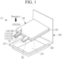
- FIG. 1 is a perspective view illustrating an electrode assembly and a case separated in a rechargeable battery according to embodiments of the present disclosure
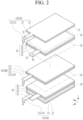
- FIG. 2 is an exploded perspective view illustrating the electrode assembly of FIG. 1
- FIG. 3 is a top plan view of the portion where a first electrode base tab is positioned in the electrode assembly of FIG. 1 as viewed from direction A.
- a rechargeable battery 10 includes an electrode assembly 100 and a case 200.
- the electrode assembly 100 includes a plurality of electrode plates 110 and 120 and a separator 130.
- Each of the electrode plates 110 and 120 include electrode base tabs 111 and 121, and are disposed to be stacked on one another.
- the first electrode plate 110 may include a first electrode base tab 111. There may be a plurality of first electrode plates 110, and there also may be a plurality of first electrode base tabs 111.
- the plurality of first electrode base tabs 111 may be joined to one other, such as by welding.
- the plurality of first electrode base tabs 111 may be assembled and joined together by welding, such as by any of laser welding, resistance welding, and ultrasonic welding.
- the second electrode plate 120 may include a second electrode base tab 121. If the electrode assembly 100 is of a stacked type, the first electrode plate 110 and the second electrode plate 120 may be stacked alternately, and the second electrode plate 120 may include a plurality of second electrode plates. There may also be a plurality of the second electrode base tabs 121. Like the first electrode base tab 111, the plurality of second electrode base tabs 121 may be joined to one another, such as by using various methods of welding.
- the above-described second electrode plate 120 may include a negative electrode, and the first electrode plate 110 may include a positive electrode, and vice versa.
- the first electrode plate 110 and the second electrode plate 120 may be electrically connected to an outside of the rechargeable battery 10 through a strip terminal (not shown).
- first electrode plate 110 will be described herein as a positive electrode and the second electrode plate 120 as a negative electrode, but the concepts are not so limited.
- a method of manufacturing the first electrode plate 110 may, for example, include pressing the first electrode current collector 112 with a press, thereby generating the first electrode base tab 111in a certain desired shape, such as a rectangular shape.
- the first electrode base tab 111 When a plurality of first electrode base tabs 111 are disposed, the first electrode base tab 111 may be defined as a multi-tab arrangement.
- the first electrode base tab 111 may be a path for current flow between the first electrode current collector 112 and a strip terminal (not shown).
- the second electrode plate 120 as a negative electrode, may be formed by applying a second electrode active material 123, such as graphite or carbon, to the second electrode current collector 122, itself formed of a metal foil such as copper, copper alloy, nickel or nickel alloy.
- the second electrode base tab 121 may extend outwardly from the second electrode current collector 122.
- a method of manufacturing the second electrode plate 120 may include pressing the second electrode current collector 122 with a press, thereby generating the second electrode base tab 121 in a desired shape, such as a rectangular shape.
- the separator 130 may be interposed between the first electrode plate 110 and the second electrode plate 120.
- the separator 130 prevents shorting between the first electrode plate 110 and the second electrode plate 120, and enables movement of lithium ions.
- the separator 130 may be larger in size than that of the first electrode plate 110 and that of the second electrode plate 120.
- the material of the separator 130 may be, for example, polyethylene, polypropylene, or a composite film of polyethylene and polypropylene, but is not limited thereto.
- Separator 130 may be cut into unit lengths and disposed between the first electrode plate 110 and the second electrode plate 120. Alternatively, a single separator 130 in a ribbon shape may be disposed between the first electrode plate 110 and the second electrode plate 120, creating a zigzag shape. Alternatively, separator 130 may be wound in one direction between the first electrode plate 110 and the second electrode plate 120. As such, the arrangement form of the separator 130 is not limited to a specific form.
- Case 200 may accommodate the electrode assembly 100, together with the electrolyte solution.
- Case 200 may be one of a pouch type, a cylindrical type, and a square type.
- Case 200 may be manufactured by bending plate-shaped exterior materials to face one another, pressing or drawing one side, and including a recess 210 on one side.
- the electrode assembly 100 may be accommodated in the recess 210.
- a sealing portion 220 may be formed on the outer periphery of the recess 210, and while the electrode assembly 100 is accommodated in the recess 210, the sealing portion 220 is sealed using a method such as thermal fusion.
- the manufacturing process of the electrode assembly 100 described above may include a first stacking step and a second stacking step.
- a full cathode which includes the remainder of the first electrode plate 110, excluding the outermost first electrode plate 110A, and a full anode, which includes the second electrode plate 120, may be stacked.
- a half cathode may be stacked on one or more of both outermost sides based on the stacking direction.
- the half cathode may include the outermost first electrode plate 110A among the first electrode plates 110.
- FIG. 1 illustrates the electrode assembly 100 in which the half cathode is stacked on both the upper and lower outermost sides of the electrode assembly 100.
- the half cathode it is also possible for the half cathode to be stacked only on the upper outermost electrode assembly 100, while the half anode is stacked on the lower outermost electrode assembly 100.
- the full cathode and the full anode have the active material applied to both sides of the base, and the half cathode has the active material applied to only one side of the base, but the concepts are not so limited.
- the second electrode plate 120 may be positioned on the upper and lower outermost sides of the electrode assembly 100.
- first electrode plate 110 may be positioned on the upper outermost side of the electrode assembly 100, and for the second electrode plate 120 to be positioned on the lower outermost side of the electrode assembly 100, although not shown.
- second electrode plate 120 it may be possible for the second electrode plate 120 to be positioned on the upper outermost side of the electrode assembly 100, and for the first electrode plate 120 to be positioned on the lower outermost side of the electrode assembly 100.
- the electrode base tab of the outermost electrode plate may be positioned in the inner region of the electrode base tabs of the remaining electrode plates, which plates are connected to one another.
- the first electrode base tab 111A of the first electrode plate 110A positioned on the outermost side among the plurality of first electrode plates 110, may be positioned in the inner region of the first electrode base tab 111B of the remaining first electrode plate 110B.
Landscapes
- Chemical & Material Sciences (AREA)
- Chemical Kinetics & Catalysis (AREA)
- Electrochemistry (AREA)
- General Chemical & Material Sciences (AREA)
- Engineering & Computer Science (AREA)
- Manufacturing & Machinery (AREA)
- Connection Of Batteries Or Terminals (AREA)
- Secondary Cells (AREA)
Abstract
Description
- The present disclosure relates to a rechargeable battery.
- Unlike a primary battery, a rechargeable battery is capable of being charged and discharged repeatedly. A low-capacity rechargeable battery that includes an electrode assembly packaged in a pack may be used as a power source for various small portable electronic devices such as cellular phones and camcorders. A high-capacity rechargeable battery that has dozens of connected electrode assemblies may be used as a power source for driving motors such as those used in an electric scooter, a hybrid automobile, and an electric automobile.
- The present disclosure attempts to overcome the conventional issues described above, and to provide a rechargeable battery with improved durability.
- A rechargeable battery according to the present disclosure includes an electrode assembly having a plurality of electrode plates each including an electrode base tab and disposed to be stacked on one another, a separator interposed between at least some of the plurality of electrode plates, and a case accommodating the electrode assembly, wherein a width of the electrode base tab of an outermost electrode plate in the electrode assembly is smaller than a width of an electrode base tab of remaining electrode plates connected to one another.
- The plurality of electrode plates may include a plurality of first electrode plates, each first electrode plate including a first electrode base tab, and a plurality of second electrode plates, each second electrode plate including a second electrode base tab.
- The first electrode base tabs may be aligned to overlap one another, and the second electrode base tabs may be aligned to overlap one another.
- The first electrode plate may be positioned on upper and lower outermost sides of the electrode assembly.
- The second electrode plate may be positioned on upper and lower outermost sides of the electrode assembly.
- The first electrode plate may be positioned on the upper outermost side of the electrode assembly, and the second electrode plate may be positioned on the lower outermost side of the electrode assembly.
- The second electrode plate may be positioned on the upper outermost side of the electrode assembly, and the first electrode plate may be positioned on the lower outermost side of the electrode assembly.
- The electrode base tab of the outermost electrode plate in the electrode assembly may be positioned in an inner region of the electrode base tabs of the remaining electrode plates which are connected to one another.
- A difference D between one end (based on a width direction) of the electrode base tab of the outermost electrode plate (e.g. one end in a width direction of the electrode base tab of an outermost electrode plate) in the electrode assembly and one end (based on the width direction) of the electrode base tab of the remaining electrode plates (e.g. one end in a width direction of an electrode base tab of remaining electrode plates) may be within a range of 0.5 mm to 2.0 mm.
- A width H1 of the electrode base tab of the outermost electrode plate of the electrode assembly may be within a range of 7.5 mm to 8.5 mm.
- A width H2 of the electrode base tabs of the remaining electrode plates, excluding the electrode base tab of the outermost electrode plate of the electrode assembly, may be within a range of 8.5 mm to 9.5 mm.
- A boundary between the electrode base tab and an electrode current collector may be rounded in the outermost electrode plate among the plurality of electrode plates.
- A radius R of the rounded portions of the electrode base tab and the electrode current collector may be within a range of 0.5 mm to 2.0 mm.
- The first electrode plate may include a first electrode current collector onto which a first electrode active material is applied, the first electrode base tab may be formed integrally with the first electrode current collector and extend outwardly from a portion of the first electrode plate, the second electrode plate may include a second electrode current collector onto which a second electrode active material is applied, and the second electrode base tab may be formed integrally with the second electrode current collector and extend outwardly from a portion of the second electrode plate.
- At least some of the above and other features of the invention are set out in the claims.
-
-
FIG. 1 is a perspective view illustrating an electrode assembly and a case separated in a rechargeable battery according to embodiments of the present disclosure. -
FIG. 2 is an exploded perspective view illustrating the electrode assembly ofFIG. 1 . -
FIG. 3 is a top plan view of the portion where a first electrode base tab is positioned in the electrode assembly ofFIG. 1 as viewed from direction A. - Preferred embodiments are described herein to illustrate the concepts. However, these embodiments are only to facilitate understanding by those skilled in the art of the present disclosure. The concepts may be embodied in many different forms and should not be construed as being limited to the embodiments set forth herein.
- In addition, in the accompanying drawings, sizes or thicknesses of various components may be exaggerated for brevity and clarity. Like numbers refer to like elements throughout. As used herein, the term "and/or" includes any one and all combinations of one or more of the associated listed items. In addition, it will be understood that when an element A is referred to as being "connected to" an element B, the element A can be directly connected to the element B, or an intervening element C may be present therebetween such that the element A and the element B are indirectly connected to each other.
- The terminology used herein is for the purpose of describing particular embodiments only and is not intended to be limiting of the disclosure. As used herein, the singular forms are intended to include the plural forms as well and conversely as well, unless the context clearly indicates otherwise. It will be further understood that the terms "comprise or include" and/or "comprising or including," when used in this specification, specify the presence of stated features, numbers, steps, operations, elements, and/or components, but do not preclude the presence or addition of one or more other features, numbers, steps, operations, elements, components, and/or groups thereof.
- It will be understood that, although the terms first, second, etc. may be used herein to describe various members, elements, regions, layers and/or sections, these members, elements, regions, layers and/or sections should not be limited by these terms. These terms are only used to distinguish one member, element, region, layer and/or section from another. Thus, for example, a first member, a first element, a first region, a first layer and/or a first section discussed below could be termed a second member, a second element, a second region, a second layer and/or a second section without departing from the teachings of the present disclosure.
- Spatially relative terms, such as "beneath," "below," "lower," "above," "upper," and the like, may be used herein for ease of description to describe one element or a feature's relationship to another element(s) or feature(s) as illustrated in the figures. It will be understood that the spatially relative terms are intended to encompass different orientations of the device in use or operation, in addition to the orientation depicted in the figures. For example, if the element or feature in the figures is turned over, elements described as "below" or "beneath" other elements or features would then be oriented "on" or "above" the other elements or features. Thus, the exemplary term "below" can encompass both orientations of above and below.
- Hereinafter, a rechargeable battery according to embodiments of the present disclosure will be described in detail with reference to the drawings.
-
FIG. 1 is a perspective view illustrating an electrode assembly and a case separated in a rechargeable battery according to embodiments of the present disclosure,FIG. 2 is an exploded perspective view illustrating the electrode assembly ofFIG. 1 , andFIG. 3 is a top plan view of the portion where a first electrode base tab is positioned in the electrode assembly ofFIG. 1 as viewed from direction A. - As shown in
FIGS. 1 to 3 , arechargeable battery 10 according to embodiments of the present disclosure includes anelectrode assembly 100 and acase 200. - The
electrode assembly 100 includes a plurality ofelectrode plates separator 130. Each of theelectrode plates electrode base tabs - The
electrode assembly 100 may be in the form of a laminate including afirst electrode plate 110, asecond electrode plate 120, with theseparator 130 being wound or stacked repeatedly. For example, theelectrode assembly 100 may be of a repeatedly wound jelly-roll type. Alternatively, there may be a plurality ofelectrode assemblies 100, of a stacked type, disposed to be stacked in multiple layers. In the present disclosure, theelectrode assembly 100 of the stacked type will be described as an example. In more detail, theelectrode plates first electrode plate 110 and thesecond electrode plate 120. - The
first electrode plate 110 may include a firstelectrode base tab 111. There may be a plurality offirst electrode plates 110, and there also may be a plurality of firstelectrode base tabs 111. The plurality of firstelectrode base tabs 111 may be joined to one other, such as by welding. For example, the plurality of firstelectrode base tabs 111 may be assembled and joined together by welding, such as by any of laser welding, resistance welding, and ultrasonic welding. - The
second electrode plate 120 may include a secondelectrode base tab 121. If theelectrode assembly 100 is of a stacked type, thefirst electrode plate 110 and thesecond electrode plate 120 may be stacked alternately, and thesecond electrode plate 120 may include a plurality of second electrode plates. There may also be a plurality of the secondelectrode base tabs 121. Like the firstelectrode base tab 111, the plurality of secondelectrode base tabs 121 may be joined to one another, such as by using various methods of welding. - The above-described
second electrode plate 120 may include a negative electrode, and thefirst electrode plate 110 may include a positive electrode, and vice versa. Thefirst electrode plate 110 and thesecond electrode plate 120 may be electrically connected to an outside of therechargeable battery 10 through a strip terminal (not shown). - Electrical connection between the first
electrode base tab 111 and a strip terminal (not shown) may be made through a first welding portion W1. For example, the plurality of firstelectrode base tabs 111 may be tightly bound together and integrally coupled to a strip terminal (not shown) through the first welding portion W1. The first welding portion W1 may be formed by ultrasonic welding, using various welding methods. - With ultrasonic welding, for example, the first
electrode base tab 111 and a strip terminal are disposed to overlap one another as welding base materials. Additionally, in this example, the firstelectrode base tab 111 and the strip terminal are pressurized between a horn (not shown) and an anvil (not shown) of the welding machine, so that joining may be achieved by vibration energy, such as frictional heat transmitted during high-frequency ultrasonic vibration. - With the first
electrode base tab 111 being made of a low-resistance metal material, for example, if the electrical resistance welding that performs welding through resistance heat is used, sufficient resistance heat for fusion and coalescence of the base material may not be generated. Therefore, ultrasonic welding may be employed more preferably than electrical resistance welding. - In addition, an electrical connection between the second
electrode base tab 121 and the strip terminal (not shown) may be made through a second welding portion W2, with the second welding portion W2 being similar in an embodiment to that of the first welding portion W1, described above. - Hereinafter, for better comprehension and ease of description, the
first electrode plate 110 will be described herein as a positive electrode and thesecond electrode plate 120 as a negative electrode, but the concepts are not so limited. - The
first electrode plate 110, as the positive electrode, may include a first electrodeactive material 113, such as a transition metal oxide, applied to the first electrodecurrent collector 112, itself being formed of a metal foil such as aluminium or aluminium alloy. The firstelectrode base tab 111 may be formed integrally with the first electrodecurrent collector 112 and may extend outwardly from a portion of thefirst electrode plate 110. - A method of manufacturing the
first electrode plate 110 may, for example, include pressing the first electrodecurrent collector 112 with a press, thereby generating the first electrode base tab 111in a certain desired shape, such as a rectangular shape. - Additionally, the first
electrode base tab 111 may be positioned so as not to overlap with the secondelectrode base tab 121. For example, based on the direction shown inFIG. 1 , the secondelectrode base tab 121 may be disposed on the right side, and the firstelectrode base tab 111 may be disposed on the left side. That is, a plurality of firstelectrode base tabs 111 may be disposed to be spaced apart from a plurality of secondelectrode base tabs 121. - When a plurality of first
electrode base tabs 111 are disposed, the firstelectrode base tab 111 may be defined as a multi-tab arrangement. The firstelectrode base tab 111 may be a path for current flow between the first electrodecurrent collector 112 and a strip terminal (not shown). - The
second electrode plate 120, as a negative electrode, may be formed by applying a second electrodeactive material 123, such as graphite or carbon, to the second electrodecurrent collector 122, itself formed of a metal foil such as copper, copper alloy, nickel or nickel alloy. The secondelectrode base tab 121 may extend outwardly from the second electrodecurrent collector 122. - A method of manufacturing the
second electrode plate 120, for example, may include pressing the second electrodecurrent collector 122 with a press, thereby generating the secondelectrode base tab 121 in a desired shape, such as a rectangular shape. - The
separator 130 may be interposed between thefirst electrode plate 110 and thesecond electrode plate 120. Theseparator 130 prevents shorting between thefirst electrode plate 110 and thesecond electrode plate 120, and enables movement of lithium ions. To this end, theseparator 130 may be larger in size than that of thefirst electrode plate 110 and that of thesecond electrode plate 120. The material of theseparator 130 may be, for example, polyethylene, polypropylene, or a composite film of polyethylene and polypropylene, but is not limited thereto. -
Separator 130 may be cut into unit lengths and disposed between thefirst electrode plate 110 and thesecond electrode plate 120. Alternatively, asingle separator 130 in a ribbon shape may be disposed between thefirst electrode plate 110 and thesecond electrode plate 120, creating a zigzag shape. Alternatively,separator 130 may be wound in one direction between thefirst electrode plate 110 and thesecond electrode plate 120. As such, the arrangement form of theseparator 130 is not limited to a specific form. -
Case 200 may accommodate theelectrode assembly 100, together with the electrolyte solution.Case 200 may be one of a pouch type, a cylindrical type, and a square type. -
Case 200 may be manufactured by bending plate-shaped exterior materials to face one another, pressing or drawing one side, and including arecess 210 on one side. Theelectrode assembly 100 may be accommodated in therecess 210. A sealingportion 220 may be formed on the outer periphery of therecess 210, and while theelectrode assembly 100 is accommodated in therecess 210, the sealingportion 220 is sealed using a method such as thermal fusion. - The manufacturing process of the
electrode assembly 100 described above may include a first stacking step and a second stacking step. - In the first stacking step, a full cathode, which includes the remainder of the
first electrode plate 110, excluding the outermostfirst electrode plate 110A, and a full anode, which includes thesecond electrode plate 120, may be stacked. - In the second stacking step, a half cathode may be stacked on one or more of both outermost sides based on the stacking direction. The half cathode may include the outermost
first electrode plate 110A among thefirst electrode plates 110. For convenience,FIG. 1 illustrates theelectrode assembly 100 in which the half cathode is stacked on both the upper and lower outermost sides of theelectrode assembly 100. However, it is also possible for the half cathode to be stacked only on the upperoutermost electrode assembly 100, while the half anode is stacked on the loweroutermost electrode assembly 100. Here, the full cathode and the full anode have the active material applied to both sides of the base, and the half cathode has the active material applied to only one side of the base, but the concepts are not so limited. - Hereinafter, the specific shape of the
electrode assembly 100 in therechargeable battery 10 having the above-described structure will be described in detail. - As shown in
FIG. 3 , a width H1 of theelectrode base tab 111A of theoutermost electrode plate 110A, in theelectrode assembly 100 included in therechargeable battery 10, according to embodiments of the present disclosure, is smaller than a width H2 of anelectrode base tab 111B of the remainingelectrode plates 110B, which are connected to one another. - As shown in
FIG. 1 , for example, thefirst electrode plate 110A may be positioned on upper and lower outermost sides of theelectrode assembly 100. With this arrangement, there may be a total of 2n+1 (n = 1, 2, 3, ...)electrode plates first electrode plate 110 may include n+1 plates, and thesecond electrode plate 120 may include n plates. Accordingly, thefirst electrode plate 110 may be positioned on the upper and lower outermost sides of theelectrode assembly 100. - Alternatively, it may be possible for the
second electrode plate 120 to be positioned on the upper and lower outermost sides of theelectrode assembly 100. - It also may be possible for the
first electrode plate 110 to be positioned on the upper outermost side of theelectrode assembly 100, and for thesecond electrode plate 120 to be positioned on the lower outermost side of theelectrode assembly 100, although not shown. Conversely, it may be possible for thesecond electrode plate 120 to be positioned on the upper outermost side of theelectrode assembly 100, and for thefirst electrode plate 120 to be positioned on the lower outermost side of theelectrode assembly 100. - The
first electrode plate 110 and thesecond electrode plate 120 may be stacked in equal numbers. - In the
electrode assembly 100 as described above, the electrode base tab of the outermost electrode plate may be positioned in the inner region of the electrode base tabs of the remaining electrode plates, which plates are connected to one another. In more detail, in the case of arechargeable battery 10 in which thefirst electrode plate 110 is positioned on the outermost side in theelectrode assembly 100, the firstelectrode base tab 111A of thefirst electrode plate 110A, positioned on the outermost side among the plurality offirst electrode plates 110, may be positioned in the inner region of the firstelectrode base tab 111B of the remainingfirst electrode plate 110B. - In addition, among the plurality of
first electrode plates 110, both ends in the width direction of the firstelectrode base tab 111A of the outermostfirst electrode plate 110A may be positioned inside both ends of the firstelectrode base tab 111B of the remainingfirst electrode plates 110B. In other words, the firstelectrode base tab 111A of thefirst electrode plate 110A, positioned on the outermost side among the plurality offirst electrode plates 110, may be disposed so as not to protrude outwardly from the firstelectrode base tab 111B of the remainingfirst electrode plates 110B. More specifically, a difference D between one end (based on the width direction) of the electrode base tab of the outermost electrode plate in theelectrode assembly 100 and one end (based on the width direction) of the electrode base tab of the remaining electrode plates may be within a range of 0.5 mm to 2.0 mm. - If the
first electrode plate 110 is positioned on the outermost side in theelectrode assembly 100, a difference D between the one end of the firstelectrode base tab 111A of the outermostfirst electrode plate 110A and the one end of the firstelectrode base tab 111B of the remainingfirst electrode plates 110B, may be within a range of 0.5 mm to 2.0 mm, in the width direction. - Among the plurality of the
first electrode plates 110, if a difference D between one end of the firstelectrode base tab 111A of the outermostfirst electrode plate 110A and one end of the firstelectrode base tab 111B of the remainingfirst electrode plate 110B, is less than 0.5 mm in the width direction, there is a possibility that stress will be concentrated at a boundary portion between the firstelectrode base tab 111A of the outermostfirst electrode plate 110A and the first electrodecurrent collector 112. - If the difference D between one end of the first
electrode base tab 111A of the outermostfirst electrode plate 110A among the plurality offirst electrode plates 110 and one end of the firstelectrode base tab 111B of the remainingfirst electrode plate 110B exceeds 2.0 mm in the width direction, the width H1 of the firstelectrode base tab 111A of the outermostfirst electrode plate 110A among the plurality offirst electrode plates 110 may be unduly small, causing an increase in resistance or difficulty establishing or maintaining an electrical connection with therechargeable battery 10 externally through a strip terminal. - If a difference D between one end (in the width direction) of the electrode base tab of the outermost electrode plate positioned in the
electrode assembly 100 and one end (in the width direction) of the electrode base tab of the remaining electrode plates, which plates are connected to one another is the same as described above, the width H1 of theelectrode base tab 111A of the outermost electrode plate positioned in theelectrode assembly 100 may be within a range of 7.5 mm to 8.5 mm. - The width H2 of the
electrode base tab 111B of the remaining electrode plates, excluding theelectrode base tab 111A of the electrode plate positioned on the outermost side in theelectrode assembly 100, may be within a range of 8.5 mm to 9.5 mm. - The boundary portion between the
electrode base tab 111A and the electrodecurrent collector 112 in the outermost electrode plate, among the plurality of electrode plates, may be rounded. The radius R of the rounded portions of theelectrode base tab 111A and the electrodecurrent collector 112 may be within a range of 0.5 mm to 2.0 mm. - As described above, because the size of the base tab of the outermost electrode plate among the plurality of
electrode plates electrode base tab 111A of the outermost electrode plate in the inner region of the remainingelectrode plates 111B. - As described above, in the
rechargeable battery 10 according to the present disclosure, the electrode base tab of the outermost electrode plate in the electrode assembly is made smaller in width than that of the electrode base tab of the remaining electrode plates, which are connected to one another. Therefore, if swelling occurs in therechargeable battery 10, stress may be dispersed to the surrounding area without being concentrated at the boundary between theelectrode base tab 111A of the outermost electrode plate and the electrode current collector. - Accordingly, the rechargeable battery according to the present disclosure may prevent sudden hard shorts from occurring due to a bent portion between the electrode base tab and the first electrode current collector caused by pressure due to swelling, resulting in intensifying stress.
- In the rechargeable battery according to the present disclosure, the electrode base tab of the outermost electrode plate in the electrode assembly is made smaller in width than that of the electrode base tab of the remaining electrode plates which are connected to one another. Therefore, if swelling occurs in the rechargeable battery, stress may be dispersed to the surrounding area without being concentrated at the boundary between the electrode base tab of the outermost electrode plate and the electrode current collector.
- Accordingly, the rechargeable battery according to the present disclosure may prevent sudden hard shorts from occurring due to the bent portion between the electrode base tab and the first electrode current collector being pressed by swelling, which causes the stress to intensify.
- The rechargeable battery may be manufactured in various shapes, among which a pouch battery may include an electrode assembly including an insulating separator interposed between a positive electrode plate and a negative electrode plate, and a thin, flexible pouch in which the electrode assembly is embedded.
- At this time, the pouch accommodates the electrode assembly in the inner space. A plurality of positive electrode tabs are coupled to the positive electrode plate of the electrode assembly, and a plurality of negative electrode tabs are coupled to the negative electrode plate.
- Here, a plurality of positive electrode tabs are generally made of the same width and disposed side by side in the vertical direction, and a plurality of negative electrode tabs are also generally made in the same manner. Therefore, if swelling occurs in a rechargeable battery, there is an issue that fracture occurs as stress acts on the edge of the positive electrode tab and the base.
- While this disclosure has been described in connection with what is presently considered to be practical embodiments, the drawings and the detailed description of the present disclosure which are described above are merely illustrative, are just used for the purpose of describing the present invention, and are not used for qualifying the meaning or limiting the scope of the present disclosure, which is disclosed in the appended claims. Therefore, it will be understood by those skilled in the art that various modifications and other equivalent embodiments may be made from the present disclosure. Accordingly, an actual technical protection scope of the present disclosure is to be defined by the claims.
-
10: Rechargeable battery 100: Electrode assembly 110: First electrode plate 111: First electrode base tab 112: First electrode current collector 113: First electrode active material 120: Second electrode plate 121: Second electrode base tab 122: Second electrode current collector 123: Second electrode active material 130: Separator 200: Case
Claims (15)
- A rechargeable battery, comprising:an electrode assembly including a plurality of electrode plates, each electrode plate including an electrode base tab and disposed to be stacked on one another, and a separator interposed between the plurality of electrode plates; anda case accommodating the electrode assembly,wherein a width of the electrode base tab of an outermost electrode plate in the electrode assembly is smaller than a width of the electrode base tab of each of the remaining electrode plates which are connected to one another.
- The rechargeable battery as claimed in claim 1, wherein
the plurality of electrode plates comprises:a plurality of first electrode plates, each first electrode plate including a first electrode base tab; anda plurality of second electrode plates, each second electrode plate including a second electrode base tab. - The rechargeable battery as claimed in claim 2, whereinthe first electrode base tabs are aligned to overlap one another,and the second electrode base tabs are aligned to overlap one another.
- The rechargeable battery as claimed in claim 2 or claim 3, wherein:(i) a first electrode plate is positioned on upper and lower outermost sides of the electrode assembly;(ii) a second electrode plate is positioned on upper and lower outermost sides of the electrode assembly;(iii) a first electrode plate is positioned on an upper outermost side of the electrode assembly, and a second electrode plate is positioned on a lower outermost side of the electrode assembly; or(iv) a second electrode plate is positioned on an upper outermost side of the electrode assembly, and a first electrode plate is positioned on a lower outermost side of the electrode assembly.
- The rechargeable battery as claimed in any one of claims 1 to 4, wherein
an electrode base tab of an outermost electrode plate in the electrode assembly is positioned in an inner region of the electrode base tabs of remaining electrode plates. - The rechargeable battery as claimed in any one of claims 1 to 5, wherein
a difference D between one end in a width direction of the electrode base tab of an outermost electrode plate in the electrode assembly and one end in a width direction of an electrode base tab of remaining electrode plates is within a range of 0.5 mm to 2.0 mm. - The rechargeable battery as claimed in any one of claims 1 to 6, wherein
a width H1 of an electrode base tab of an outermost electrode plate of the electrode assembly is within a range of 7.5 mm to 8.5 mm. - The rechargeable battery as claimed in any one of claims 1 to 7, wherein
a width H2 of electrode base tabs of remaining electrode plates, excluding an electrode base tab of an outermost electrode plate of the electrode assembly, is within a range of 8.5 mm to 9.5 mm. - The rechargeable battery as claimed in any one of claims 1 to 8, whereina boundary between the electrode base tab and an electrode current collector in an outermost electrode plate among the plurality of electrode plates is rounded, optionally whereina radius R of rounded portions of the electrode base tab and the electrode current collector is within a range of 0.5 mm to 2.0 mm.
- The rechargeable battery as claimed in any one of claims 2 to 9, whereina first electrode plate comprises a first electrode current collector onto which a first electrode active material is applied,a first electrode base tab is formed integrally with the first electrode current collector and extends outwardly from a portion of the first electrode plate,a second electrode plate comprises a second electrode current collector onto which a second electrode active material is applied,and a second electrode base tab is formed integrally with the second electrode current collector and extends outwardly from a portion of the second electrode plate.
- A rechargeable battery, comprising:an electrode assembly including a plurality of electrode plates, each electrode plate including an electrode base tab and disposed to be stacked on one another, and a separator interposed between the plurality of electrode plates, the plurality of electrode plates comprises a plurality of first electrode plates, each first electrode plate including a first electrode base tab, and a plurality of second electrode plates, each second electrode plate including a second electrode base tab, the first electrode tabs disposed to overlap with one another, and the second electrode tabs disposed to overlap with one another; anda case accommodating the electrode assembly.
- A method of making a rechargeable battery comprising:providing an electrode assembly having a plurality of electrode plates, each electrode plate having an electrode base tab;stacking the electrode plates on one another, with a width of a base tab of an outermost electrode plate being smaller than a width of a base tab of other electrode plates;interposing a separator between stacked electrode plates;providing a case accommodating the electrode assembly.
- The method as claimed in claim 12, wherein the plurality of electrode plates includes a plurality of first electrode plates, each first electrode plate including a first electrode base tab, and a plurality of second electrode plates, each second electrode plate including a second electrode base tab, and wherein the electrode plates are stacked such that the first electrode base tabs overlap with one another and the second electrode base tabs overlap with one another.
- The method as claimed in claim 13, wherein:(i) the electrode plates are stacked such that a first electrode plate is positioned on upper and lower outmost sides of the electrode assembly; or(ii) the electrode plates are stacked such that a second electrode plate is positioned on upper and lower outmost sides of the electrode assembly.
- The method as claimed in claim 13 or claim 14, wherein the electrode plates are stacked such that an electrode base tab of an outermost electrode plate in the electrode assembly is positioned in an inner region of the electrode base tabs of remaining electrode plates.
Applications Claiming Priority (1)
| Application Number | Priority Date | Filing Date | Title |
|---|---|---|---|
| KR1020230113032A KR20250031494A (en) | 2023-08-28 | 2023-08-28 | Rechargeable battery |
Publications (3)
| Publication Number | Publication Date |
|---|---|
| EP4517896A2 true EP4517896A2 (en) | 2025-03-05 |
| EP4517896A3 EP4517896A3 (en) | 2025-05-07 |
| EP4517896B1 EP4517896B1 (en) | 2025-12-17 |
Family
ID=92593056
Family Applications (1)
| Application Number | Title | Priority Date | Filing Date |
|---|---|---|---|
| EP24197042.5A Active EP4517896B1 (en) | 2023-08-28 | 2024-08-28 | Rechargeable battery |
Country Status (4)
| Country | Link |
|---|---|
| US (1) | US20250070410A1 (en) |
| EP (1) | EP4517896B1 (en) |
| KR (1) | KR20250031494A (en) |
| CN (1) | CN119542697A (en) |
Family Cites Families (6)
| Publication number | Priority date | Publication date | Assignee | Title |
|---|---|---|---|---|
| US9077027B2 (en) * | 2010-03-04 | 2015-07-07 | Samsung Sdi Co., Ltd. | Electrode assembly and secondary battery using the same |
| KR101254691B1 (en) * | 2010-08-17 | 2013-04-15 | 주식회사 엘지화학 | Secondary electric cell with enhanced lead structure |
| JP5844052B2 (en) * | 2011-02-04 | 2016-01-13 | 三洋電機株式会社 | Multilayer battery and method for manufacturing the same |
| KR102125059B1 (en) * | 2016-06-07 | 2020-06-19 | 주식회사 엘지화학 | Electrode Assembly Comprising Electrode Plates Having Electrode Plate Extending Part |
| KR102264701B1 (en) * | 2016-07-20 | 2021-06-11 | 삼성에스디아이 주식회사 | Rechargeable battery |
| KR101890844B1 (en) * | 2017-11-24 | 2018-08-22 | 주식회사 리베스트 | An electrode assembly with improved safety in use by structure of outermost electrodes and material of current collectors, and lithium ion battery with the electrode assembly |
-
2023
- 2023-08-28 KR KR1020230113032A patent/KR20250031494A/en active Pending
-
2024
- 2024-08-26 US US18/814,940 patent/US20250070410A1/en active Pending
- 2024-08-28 CN CN202411187003.0A patent/CN119542697A/en active Pending
- 2024-08-28 EP EP24197042.5A patent/EP4517896B1/en active Active
Also Published As
| Publication number | Publication date |
|---|---|
| CN119542697A (en) | 2025-02-28 |
| EP4517896A3 (en) | 2025-05-07 |
| KR20250031494A (en) | 2025-03-07 |
| US20250070410A1 (en) | 2025-02-27 |
| EP4517896B1 (en) | 2025-12-17 |
Similar Documents
| Publication | Publication Date | Title |
|---|---|---|
| US20250025957A1 (en) | Electrode Having Improved Electrode Tab Welding Characteristics and Secondary Battery Comprising the Same | |
| JP7694432B2 (en) | secondary battery | |
| US8236441B2 (en) | Battery cell design and methods of its construction | |
| KR101310176B1 (en) | Electric energy storage device and its manufacturing method | |
| CN100541881C (en) | Low impedance layered battery apparatus and method of making same | |
| US8530068B2 (en) | Square battery and manufacturing method of the same | |
| KR102780825B1 (en) | Secondary battery and manufacturing method therof | |
| KR101072681B1 (en) | Laminate secondary battery | |
| JP2006156401A (en) | Secondary battery | |
| US20220352606A1 (en) | Secondary battery and method for manufacturing same | |
| US20110076544A1 (en) | Stack type battery | |
| JP2025063328A (en) | Secondary battery | |
| JP7299816B2 (en) | Stacked battery manufacturing method, stacked battery manufacturing apparatus, and stacked battery | |
| KR101486623B1 (en) | Pouch type secondary battery and method for manufacturing the same | |
| JP2018041818A (en) | Power storage device, power storage module, and method for manufacturing power storage module | |
| EP4517896B1 (en) | Rechargeable battery | |
| JP7808280B2 (en) | Electricity storage device and method for manufacturing the same | |
| JP7285817B2 (en) | SEALED BATTERY AND METHOD OF MANUFACTURING SEALED BATTERY | |
| KR102108208B1 (en) | Cylindrical Secondary Battery Having Circular Electrode | |
| US20250087834A1 (en) | Electrode assembly and rechargeable battery including the same | |
| JP2010027494A (en) | Electricity storage device, and manufacturing method thereof | |
| KR102261720B1 (en) | Battery Cell Comprising Surface-treated Current Collector by Laser Irradiation | |
| US20260051633A1 (en) | Secondary Battery and Manufacturing Method Thereof | |
| JP6285513B1 (en) | Power storage module | |
| KR102803517B1 (en) | secondary battery |
Legal Events
| Date | Code | Title | Description |
|---|---|---|---|
| PUAI | Public reference made under article 153(3) epc to a published international application that has entered the european phase |
Free format text: ORIGINAL CODE: 0009012 |
|
| STAA | Information on the status of an ep patent application or granted ep patent |
Free format text: STATUS: REQUEST FOR EXAMINATION WAS MADE |
|
| 17P | Request for examination filed |
Effective date: 20240828 |
|
| AK | Designated contracting states |
Kind code of ref document: A2 Designated state(s): AL AT BE BG CH CY CZ DE DK EE ES FI FR GB GR HR HU IE IS IT LI LT LU LV MC ME MK MT NL NO PL PT RO RS SE SI SK SM TR |
|
| PUAL | Search report despatched |
Free format text: ORIGINAL CODE: 0009013 |
|
| AK | Designated contracting states |
Kind code of ref document: A3 Designated state(s): AL AT BE BG CH CY CZ DE DK EE ES FI FR GB GR HR HU IE IS IT LI LT LU LV MC ME MK MT NL NO PL PT RO RS SE SI SK SM TR |
|
| RIC1 | Information provided on ipc code assigned before grant |
Ipc: H01M 10/04 20060101AFI20250331BHEP |
|
| GRAP | Despatch of communication of intention to grant a patent |
Free format text: ORIGINAL CODE: EPIDOSNIGR1 |
|
| STAA | Information on the status of an ep patent application or granted ep patent |
Free format text: STATUS: GRANT OF PATENT IS INTENDED |
|
| INTG | Intention to grant announced |
Effective date: 20250819 |
|
| GRAS | Grant fee paid |
Free format text: ORIGINAL CODE: EPIDOSNIGR3 |
|
| GRAA | (expected) grant |
Free format text: ORIGINAL CODE: 0009210 |
|
| STAA | Information on the status of an ep patent application or granted ep patent |
Free format text: STATUS: THE PATENT HAS BEEN GRANTED |
|
| AK | Designated contracting states |
Kind code of ref document: B1 Designated state(s): AL AT BE BG CH CY CZ DE DK EE ES FI FR GB GR HR HU IE IS IT LI LT LU LV MC ME MK MT NL NO PL PT RO RS SE SI SK SM TR |
|
| REG | Reference to a national code |
Ref country code: CH Ref legal event code: F10 Free format text: ST27 STATUS EVENT CODE: U-0-0-F10-F00 (AS PROVIDED BY THE NATIONAL OFFICE) Effective date: 20251217 Ref country code: GB Ref legal event code: FG4D |
|
| REG | Reference to a national code |
Ref country code: DE Ref legal event code: R096 Ref document number: 602024001733 Country of ref document: DE |
|
| REG | Reference to a national code |
Ref country code: LT Ref legal event code: MG9D |
|
| PG25 | Lapsed in a contracting state [announced via postgrant information from national office to epo] |
Ref country code: NO Free format text: LAPSE BECAUSE OF FAILURE TO SUBMIT A TRANSLATION OF THE DESCRIPTION OR TO PAY THE FEE WITHIN THE PRESCRIBED TIME-LIMIT Effective date: 20260317 |
|
| PG25 | Lapsed in a contracting state [announced via postgrant information from national office to epo] |
Ref country code: FI Free format text: LAPSE BECAUSE OF FAILURE TO SUBMIT A TRANSLATION OF THE DESCRIPTION OR TO PAY THE FEE WITHIN THE PRESCRIBED TIME-LIMIT Effective date: 20251217 Ref country code: HR Free format text: LAPSE BECAUSE OF FAILURE TO SUBMIT A TRANSLATION OF THE DESCRIPTION OR TO PAY THE FEE WITHIN THE PRESCRIBED TIME-LIMIT Effective date: 20251217 |
|
| PG25 | Lapsed in a contracting state [announced via postgrant information from national office to epo] |
Ref country code: RS Free format text: LAPSE BECAUSE OF FAILURE TO SUBMIT A TRANSLATION OF THE DESCRIPTION OR TO PAY THE FEE WITHIN THE PRESCRIBED TIME-LIMIT Effective date: 20260317 |
|
| REG | Reference to a national code |
Ref country code: NL Ref legal event code: MP Effective date: 20251217 |
|
| PG25 | Lapsed in a contracting state [announced via postgrant information from national office to epo] |
Ref country code: LV Free format text: LAPSE BECAUSE OF FAILURE TO SUBMIT A TRANSLATION OF THE DESCRIPTION OR TO PAY THE FEE WITHIN THE PRESCRIBED TIME-LIMIT Effective date: 20251217 |