EP4517852A1 - Anordnung mit batteriezelle und verfahren zur rückgewinnung eines oder mehrerer gase, die während der bildung einer batterie ausgesendet werden - Google Patents
Anordnung mit batteriezelle und verfahren zur rückgewinnung eines oder mehrerer gase, die während der bildung einer batterie ausgesendet werden Download PDFInfo
- Publication number
- EP4517852A1 EP4517852A1 EP24197767.7A EP24197767A EP4517852A1 EP 4517852 A1 EP4517852 A1 EP 4517852A1 EP 24197767 A EP24197767 A EP 24197767A EP 4517852 A1 EP4517852 A1 EP 4517852A1
- Authority
- EP
- European Patent Office
- Prior art keywords
- preformed
- additional
- assembly
- pipe
- Prior art date
- Legal status (The legal status is an assumption and is not a legal conclusion. Google has not performed a legal analysis and makes no representation as to the accuracy of the status listed.)
- Pending
Links
Images


Classifications
-
- H—ELECTRICITY
- H01—ELECTRIC ELEMENTS
- H01M—PROCESSES OR MEANS, e.g. BATTERIES, FOR THE DIRECT CONVERSION OF CHEMICAL ENERGY INTO ELECTRICAL ENERGY
- H01M50/00—Constructional details or processes of manufacture of the non-active parts of electrochemical cells other than fuel cells, e.g. hybrid cells
- H01M50/10—Primary casings; Jackets or wrappings
- H01M50/102—Primary casings; Jackets or wrappings characterised by their shape or physical structure
- H01M50/105—Pouches or flexible bags
-
- H—ELECTRICITY
- H01—ELECTRIC ELEMENTS
- H01M—PROCESSES OR MEANS, e.g. BATTERIES, FOR THE DIRECT CONVERSION OF CHEMICAL ENERGY INTO ELECTRICAL ENERGY
- H01M10/00—Secondary cells; Manufacture thereof
- H01M10/42—Methods or arrangements for servicing or maintenance of secondary cells or secondary half-cells
- H01M10/52—Removing gases inside the secondary cell, e.g. by absorption
-
- H—ELECTRICITY
- H01—ELECTRIC ELEMENTS
- H01M—PROCESSES OR MEANS, e.g. BATTERIES, FOR THE DIRECT CONVERSION OF CHEMICAL ENERGY INTO ELECTRICAL ENERGY
- H01M4/00—Electrodes
- H01M4/02—Electrodes composed of, or comprising, active material
- H01M4/04—Processes of manufacture in general
- H01M4/0438—Processes of manufacture in general by electrochemical processing
- H01M4/044—Activating, forming or electrochemical attack of the supporting material
- H01M4/0445—Forming after manufacture of the electrode, e.g. first charge, cycling
- H01M4/0447—Forming after manufacture of the electrode, e.g. first charge, cycling of complete cells or cells stacks
-
- H—ELECTRICITY
- H01—ELECTRIC ELEMENTS
- H01M—PROCESSES OR MEANS, e.g. BATTERIES, FOR THE DIRECT CONVERSION OF CHEMICAL ENERGY INTO ELECTRICAL ENERGY
- H01M50/00—Constructional details or processes of manufacture of the non-active parts of electrochemical cells other than fuel cells, e.g. hybrid cells
- H01M50/10—Primary casings; Jackets or wrappings
- H01M50/116—Primary casings; Jackets or wrappings characterised by the material
- H01M50/124—Primary casings; Jackets or wrappings characterised by the material having a layered structure
-
- H—ELECTRICITY
- H01—ELECTRIC ELEMENTS
- H01M—PROCESSES OR MEANS, e.g. BATTERIES, FOR THE DIRECT CONVERSION OF CHEMICAL ENERGY INTO ELECTRICAL ENERGY
- H01M50/00—Constructional details or processes of manufacture of the non-active parts of electrochemical cells other than fuel cells, e.g. hybrid cells
- H01M50/30—Arrangements for facilitating escape of gases
- H01M50/394—Gas-pervious parts or elements
-
- Y—GENERAL TAGGING OF NEW TECHNOLOGICAL DEVELOPMENTS; GENERAL TAGGING OF CROSS-SECTIONAL TECHNOLOGIES SPANNING OVER SEVERAL SECTIONS OF THE IPC; TECHNICAL SUBJECTS COVERED BY FORMER USPC CROSS-REFERENCE ART COLLECTIONS [XRACs] AND DIGESTS
- Y02—TECHNOLOGIES OR APPLICATIONS FOR MITIGATION OR ADAPTATION AGAINST CLIMATE CHANGE
- Y02E—REDUCTION OF GREENHOUSE GAS [GHG] EMISSIONS, RELATED TO ENERGY GENERATION, TRANSMISSION OR DISTRIBUTION
- Y02E60/00—Enabling technologies; Technologies with a potential or indirect contribution to GHG emissions mitigation
- Y02E60/10—Energy storage using batteries
Definitions
- the present invention relates to battery cells and in particular to the degassing of battery cells during their formation.
- the present invention relates to an assembly comprising a battery cell and a method for recovering one or more gases emitted during the formation of a battery, in particular emitted during the formation cycle of the battery during which the battery undergoes several charge and discharge cycles.
- a battery cell may undergo at least one charge and discharge cycle during its formation during which gases are emitted. These gases can cause parasitic reactions with materials in the cell and degrade the performance of the battery, in particular its durability.
- a cell degassing step is generally carried out in an inert environment, for example in a glove box under inert gas, in order to guarantee the safety of the operator carrying out the degassing.
- the present invention therefore aims to overcome all or part of the aforementioned drawbacks, to improve the performance of a battery cell, and to simplify the battery cell degassing operation.
- the present invention relates to an assembly comprising a battery cell having electrodes, an electrolyte, and a pouch housing the electrodes and the electrolyte.
- the set further includes an additional pocket and a pipe connecting the pocket to the additional pocket.
- the pocket and the additional pocket communicate only through the conduit.
- the gases emitted by the battery cell during its formation can flow through the conduit to the pocket additional, thus reducing the amount of gas emitted in contact with the electrodes and the electrolyte and therefore the parasitic reactions degrading the performance and durability of the battery cell.
- the assembly may include a fluid preventer configured to allow flow of fluid from the bag to the additional bag and to prevent flow of fluid from the additional bag to the bag.
- gases emitted into the pocket and flowing from the pocket to the additional pocket through the conduit are trapped in the additional pocket and cannot degrade the performance of the battery cell.
- the fluid non-return device can be arranged in the additional pocket.
- the pocket and the additional pocket may be connected together by a flat portion inside which the conduit extends.
- Said planar portion may extend projecting from an edge of the pocket. Said planar portion may extend projecting from an edge of the additional pocket.
- the pocket and the additional pocket may be formed from a preformed top sheet and a preformed bottom sheet joined together.
- the preformed top and bottom sheets may each comprise aluminum coated with a film of a polymeric material.
- Aluminum provides a protective layer for the battery cell.
- the preformed top and bottom sheets are heat sealed together.
- the polymer material film of the preformed upper sheet is heat-sealed to the polymer material film of the preformed lower sheet.
- the conduit may be formed of a polymeric material.
- the pipe formed from a polymer material may become clogged, particularly by subjecting the pipe to high temperature, for example example during a heat-sealing operation. It is then possible to cut the pipe so that the bag and the additional bag are watertight. In particular, this operation does not require the use of an inert environment, and can in particular be carried out in an anhydrous room.
- Said portion of the preformed top sheet and said other portion of the preformed top sheet are complementary to each other and form the preformed top sheet.
- Said portion of the preformed bottom sheet and said other portion of the preformed bottom sheet are complementary to each other and form the preformed bottom sheet.
- the pocket forming step may include inserting a metal rod into the conduit.
- the pipe is protected during the formation of the pocket.
- the metal rod is advantageously removed before the step of forming the additional pocket.
- the emitted gases contained in the additional pocket can then be analyzed to verify the proper progress of the battery formation, and thus verify that the battery meets the quality and performance standards required for its marketing.
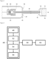
- THE figures 1 has 3 represent an assembly 2 comprising a battery cell 4 provided with a pocket 6, and an additional pocket 8.
- the pocket 6 is intended to store electrical energy.
- the additional pocket 8 is intended to allow the recovery of gases generated in the pocket 6, in particular during the formation cycle of the battery cell 4.
- the battery is, for example, intended to power an electric motor vehicle.
- the battery cell 4 comprises electrodes 10 and an electrolyte (not shown) housed in the pocket 6, as well as two current collectors 12 each extending through a wall of the pocket 6.
- the electrodes 10 of the cell 4 comprise at least one anode, for example composed of graphite, and at least one cathode, for example composed of a lithium or sodium-based material.
- the electrolyte is, for example, a liquid or solid polymer electrolyte.
- the pocket 6 comprises an upper wall 14 and a lower wall 16 opposite the upper wall 14, as well as peripheral edges 18 connecting the upper and lower walls 14, 16 of the pocket 6 so as to form a space internally.
- the additional pocket 8 also comprises an upper wall 20 and a lower wall 22 opposite the upper wall 20, as well as peripheral edges 24 connecting the upper and lower walls 20, 22 of the additional pocket 8 so as to form a space internally.
- the assembly 2 comprises a flat portion 26 extending from the peripheral edges 18 of the pocket 6 and an additional flat portion 28 extending from the peripheral edges 24 of the additional pocket 8.
- the flat portion 26 and the additional flat portion 28 form a single-piece assembly. In other words, the flat portion 26 is integral with the additional flat portion 28.
- the assembly 2 further comprises a pipe 30 connecting the pocket 6 to the additional pocket 8.
- the interior space of the pocket 6 and the interior space of the additional pocket 8 communicate fluidically only through the pipe 30.
- a first end 32 of the pipe 30 extends through a peripheral edge 18 of the pocket 6 and opens into the interior space of the pocket 6.
- a second end 34 of the pipe 30 opposite the first end 32 of the pipe 30 extends through a peripheral edge 24 of the additional pocket 8 and opens into the interior space of the additional pocket 8.
- the pipe 30 extends through the flat wall 26 and the additional flat wall 28.
- Line 30 comprises, for example, a needle.
- the pipe 30 is, for example, made of a polymer material.
- the assembly 2 comprises a fluid non-return device 36 allowing the circulation of a fluid from the bag 6 to the additional bag 8 and preventing the circulation of a fluid from the additional bag 8 to the bag 6.
- the fluid non-return device 36 here comprises a fluid non-return valve arranged in the interior space of the additional pocket 8.
- the second end 34 of the pipe 30 has a shape suitable for fixing the fluid non-return valve there.
- the fluid check valve includes a ball and a spring urging the ball into a position closing off the line 30.
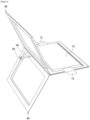
- the pocket 6 and the additional pocket 8 are formed from a preformed upper sheet 38 and a preformed lower sheet 40 joined together ( figure 6 ).
- the preformed inner and upper sheets 38, 40 are heat sealed together to form the pocket 6, the flat portion 26, the additional pocket 8 and the additional flat portion 28.
- the upper and lower sheets 38, 40 are preformed so as to give the shape of the assembly 2 when assembling the preformed upper sheet 38 and the preformed lower sheet 40.
- the preformed upper and lower sheets 38, 40 are advantageously identical to each other.
- the preformed top sheet 38 comprises ( figure 7 ), for example, an aluminum sheet 42 covered, at least on its face oriented towards the preformed lower sheet 40, by a film 44 of a polymer material.
- the preformed upper sheet 38 comprises a portion provided with a recess (not referenced) intended to partly form the pocket 6, in particular to form the upper wall 14 of the pocket 6, as well as another portion provided with an additional recess (not referenced) intended to partly form the additional pocket 8, in particular to form the upper wall 20 of the additional pocket 8.
- the preformed lower sheet 40 comprises ( figure 7 ), for example, an aluminum sheet 42 covered, at least on its face oriented towards the preformed upper sheet 38, by a film 44 of a polymer material.
- the preformed lower sheet 40 comprises a portion provided with a recess (not referenced) intended to partly form the pocket 6, in particular to form the lower wall 16 of the pocket 6, as well as another portion provided with an additional recess (not referenced) intended to partly form the additional pocket 8, in particular to form the lower wall 22 of the additional pocket 8.
- the recess of the preformed lower sheet 40 is intended to form the pocket 6 of the assembly 2 together with the recess of the preformed upper sheet 38.
- the additional recess of the preformed lower sheet 40 is intended to form the additional pocket 8 of the assembly 2 together with the additional recess of the preformed upper sheet 38.
- FIG. 4 schematically represents a method for recovering a gas emitted during the formation of the battery cell 4.
- this gas is emitted when, following the formation of the battery cell 4, the latter undergoes at least one charge and discharge cycle to stabilize its active materials and thus minimize undesirable chemical reactions during subsequent charge and discharge cycles.
- step 46 of producing the assembly 2 comprising a sub-step 48 of forming the pocket 6 illustrated in Figures 5 to 9 .
- the electrodes 10 are positioned in the recess of the part of the preformed lower sheet 40, the current collectors 12 are connected to the electrodes 10, the current collectors 12 are positioned in contact with a flat periphery of the part of the preformed lower sheet 40 extending the recess of the preformed lower sheet 40, the current collectors 12 being arranged on either side of the electrodes 10.
- the pipe 30 is positioned so that the first end 32 of the pipe 30 is opposite the electrodes 10 and so that the second end 34 of the pipe 30 is opposite the electrodes 10 relative to the first end 32 of the pipe 30.
- a metal rod 50 is inserted into the pipe 30.
- a flat perimeter of the part of the preformed upper sheet 38 extending the recess of the part of the preformed upper sheet 38 is brought into contact with the perimeter of the part of the preformed lower sheet 40 so that the electrodes 10 are housed in the pocket 6 formed by the recesses of the preformed upper and lower sheets 38, 40, so that the first end 32 of the pipe 30 opens into the pocket 6 and so that the current collectors 12 are enclosed between the preformed upper and lower sheets 38, 40.
- the portions of the preformed upper and lower sheets 38, 40 are welded, thereby forming the flat portion 26.
- the portion of the preformed upper sheet 38 is heat-sealed to the portion of the preformed lower sheet 40 by heating the peripheries of the recesses of the preformed upper and lower sheets 38, 40 so as to join them.
- the films 44 of polymer material covering the aluminum sheets 42 of the preformed upper and lower sheets 38, 40 are heated to a temperature greater than 160°C and fuse ( figure 8 ).
- the metal rod 50 having protected the pipe 30 during heat welding, is then removed.
- a sub-step 54 of positioning the fluid non-return device 36 is carried out.
- the fluid non-return valve is inserted into the second end 34 of the pipe 30 of suitable shape.
- a sub-step 56 of forming the additional pocket 8 is carried out.
- a flat periphery of the other part of the preformed upper sheet 38 extending the additional recess of the other part of the preformed upper sheet 38 is brought into contact with a flat periphery of the other part of the preformed lower sheet 40 extending the additional recess of the other part of the preformed lower sheet 40.
- the other parts of the preformed upper and lower sheets 38, 40 are welded, in particular heat-sealed, thus forming the additional flat portion 28.
- the process for recovering emitted gas is continued by a step 58 of cycling the battery cell 4 comprising several charging and discharging cycles of the battery cell 4.
- the gases are then generated in the pocket 6 and then evacuated to the additional pocket 8 through the pipe 30.
- a step 60 of cutting the pipe 30 is carried out so that the pocket 6 is separated from the additional pocket 8 and is sealed.
- the flat portion 26 and the additional flat portion 28 in which the pipe 30 extends are heat-sealed so as to seal the pipe 30.
- a cutting device is used to separate the parts of the preformed upper and lower sheets 38, 40 from the other parts of the preformed upper and lower sheets 38, 40, the flat portion 26 then being separated from the flat portion 28, as illustrated in figure 9 .
- the additional pocket 8 can now be analyzed to verify the correct formation of the battery cell 4.
Landscapes
- Chemical & Material Sciences (AREA)
- Chemical Kinetics & Catalysis (AREA)
- Electrochemistry (AREA)
- General Chemical & Material Sciences (AREA)
- Engineering & Computer Science (AREA)
- Manufacturing & Machinery (AREA)
- Sealing Battery Cases Or Jackets (AREA)
- Secondary Cells (AREA)
Applications Claiming Priority (1)
| Application Number | Priority Date | Filing Date | Title |
|---|---|---|---|
| FR2309171A FR3152657A1 (fr) | 2023-08-31 | 2023-08-31 | Ensemble comprenant une cellule de batterie et procédé de récupération d’un ou plusieurs gaz émis lors de la formation d’une batterie |
Publications (1)
| Publication Number | Publication Date |
|---|---|
| EP4517852A1 true EP4517852A1 (de) | 2025-03-05 |
Family
ID=88585270
Family Applications (1)
| Application Number | Title | Priority Date | Filing Date |
|---|---|---|---|
| EP24197767.7A Pending EP4517852A1 (de) | 2023-08-31 | 2024-08-30 | Anordnung mit batteriezelle und verfahren zur rückgewinnung eines oder mehrerer gase, die während der bildung einer batterie ausgesendet werden |
Country Status (2)
| Country | Link |
|---|---|
| EP (1) | EP4517852A1 (de) |
| FR (1) | FR3152657A1 (de) |
Citations (6)
| Publication number | Priority date | Publication date | Assignee | Title |
|---|---|---|---|---|
| US20060216591A1 (en) * | 2005-03-28 | 2006-09-28 | Lee Hyung B | Pouch type lithium secondary battery and method of fabricating the same |
| US20070072071A1 (en) * | 2005-09-28 | 2007-03-29 | Hyungbok Lee | Pouch-type lithium secondary battery and fabricating method thereof |
| US20120321923A1 (en) * | 2011-06-17 | 2012-12-20 | Samsung Sdi Co., Ltd. | Secondary battery |
| KR101806411B1 (ko) * | 2013-08-22 | 2017-12-07 | 주식회사 엘지화학 | 가스이동파이프를 포함하는 배터리 팩 |
| EP3671898A1 (de) * | 2018-04-23 | 2020-06-24 | Lg Chem, Ltd. | Beutelartige sekundärbatterie mit gasentladungsmitteln |
| KR20230008616A (ko) * | 2021-07-07 | 2023-01-16 | (주)엔에스 | 파우치형 이차전지의 디게싱 방법 |
-
2023
- 2023-08-31 FR FR2309171A patent/FR3152657A1/fr active Pending
-
2024
- 2024-08-30 EP EP24197767.7A patent/EP4517852A1/de active Pending
Patent Citations (6)
| Publication number | Priority date | Publication date | Assignee | Title |
|---|---|---|---|---|
| US20060216591A1 (en) * | 2005-03-28 | 2006-09-28 | Lee Hyung B | Pouch type lithium secondary battery and method of fabricating the same |
| US20070072071A1 (en) * | 2005-09-28 | 2007-03-29 | Hyungbok Lee | Pouch-type lithium secondary battery and fabricating method thereof |
| US20120321923A1 (en) * | 2011-06-17 | 2012-12-20 | Samsung Sdi Co., Ltd. | Secondary battery |
| KR101806411B1 (ko) * | 2013-08-22 | 2017-12-07 | 주식회사 엘지화학 | 가스이동파이프를 포함하는 배터리 팩 |
| EP3671898A1 (de) * | 2018-04-23 | 2020-06-24 | Lg Chem, Ltd. | Beutelartige sekundärbatterie mit gasentladungsmitteln |
| KR20230008616A (ko) * | 2021-07-07 | 2023-01-16 | (주)엔에스 | 파우치형 이차전지의 디게싱 방법 |
Also Published As
| Publication number | Publication date |
|---|---|
| FR3152657A1 (fr) | 2025-03-07 |
Similar Documents
| Publication | Publication Date | Title |
|---|---|---|
| EP3826083B1 (de) | Akku und verfahren zum schweissen eines akkus | |
| EP0913874A1 (de) | Verschlossener Akkumulator mit mehrschichtiger Ummantelung | |
| EP4002572A1 (de) | Metall-ionen-akku mit entgasungsleitung, batteriemodul oder entsprechender batteriepack mit flüssigkeitskühlung | |
| FR3114917A1 (fr) | Carter de batterie | |
| WO2019129734A1 (fr) | Couvercle d'element electrochimique a conduction thermique renforcee | |
| EP0867960A1 (de) | Elektrochemischer Generator mit verbesserter Sicherheit | |
| WO2017149217A1 (fr) | Echangeur de chaleur a paroi souple pour la gestion thermique d'une batterie électrique. | |
| CN100372164C (zh) | 二次电池、它的盖组件以及因此安装安全阀的方法 | |
| EP3987240A1 (de) | Flüssigkeitszirkulationswärmetauscher und verbinder für einen solchen wärmetauscher | |
| EP4517852A1 (de) | Anordnung mit batteriezelle und verfahren zur rückgewinnung eines oder mehrerer gase, die während der bildung einer batterie ausgesendet werden | |
| FR3104830A1 (fr) | Compartiment pour un équipement susceptible de dégager de la chaleur | |
| FR3057708A1 (fr) | Procede de fabrication d'une batterie au lithium en sachet, et ensemble comprenant un sachet ferme renfermant des electrodes, destine a etre rempli d'un electrolyte liquide | |
| FR3127333A1 (fr) | Systeme de batterie de stockage d’energie electrique comprenant un systeme de securite de degazage | |
| EP0969533A1 (de) | Spannvorrichtung für Monoblock-Batterie | |
| WO2021228782A1 (fr) | Etui pour cellule électrochimique pour batterie, agencement de cellules électrochimiques pour batterie comprenant un tel étui et procédé de fabrication d'un tel agencement de cellules | |
| FR3122040A1 (fr) | Systeme de batterie de stockage d’energie electrique comprenant un systeme de securite de degazage | |
| FR3098763A1 (fr) | Systeme de batterie comprenant un bac a batterie | |
| FR3148120A1 (fr) | Systeme de batterie de stockage d’energie electrique comprenant un systeme de securite de degazage | |
| FR3106700A1 (fr) | Compartiment pour un équipement susceptible de dégager de la chaleur | |
| WO2020058586A1 (fr) | Compartiment pour dispositif de stockage d'énergie électrique pour véhicule automobile | |
| FR3088593A1 (fr) | Compartiment pour dispositif de stockage d'energie electrique pour vehicule automobile | |
| EP4465394A1 (de) | Elektrochemische zelle für eine elektrische batterie | |
| FR3103968A1 (fr) | Compartiment pour un équipement susceptible de dégager de la chaleur | |
| WO2024132481A1 (fr) | Module d'accumulateurs apte à la gestion d'une surpression interne | |
| FR3119934A1 (fr) | Cellule de batterie et procédé de fabrication d’une telle cellule |
Legal Events
| Date | Code | Title | Description |
|---|---|---|---|
| PUAI | Public reference made under article 153(3) epc to a published international application that has entered the european phase |
Free format text: ORIGINAL CODE: 0009012 |
|
| STAA | Information on the status of an ep patent application or granted ep patent |
Free format text: STATUS: THE APPLICATION HAS BEEN PUBLISHED |
|
| AK | Designated contracting states |
Kind code of ref document: A1 Designated state(s): AL AT BE BG CH CY CZ DE DK EE ES FI FR GB GR HR HU IE IS IT LI LT LU LV MC ME MK MT NL NO PL PT RO RS SE SI SK SM TR |
|
| STAA | Information on the status of an ep patent application or granted ep patent |
Free format text: STATUS: REQUEST FOR EXAMINATION WAS MADE |
|
| 17P | Request for examination filed |
Effective date: 20250905 |