EP4517791A1 - Contact system for an on-load tap changer and on-load tap changer - Google Patents
Contact system for an on-load tap changer and on-load tap changer Download PDFInfo
- Publication number
- EP4517791A1 EP4517791A1 EP23194602.1A EP23194602A EP4517791A1 EP 4517791 A1 EP4517791 A1 EP 4517791A1 EP 23194602 A EP23194602 A EP 23194602A EP 4517791 A1 EP4517791 A1 EP 4517791A1
- Authority
- EP
- European Patent Office
- Prior art keywords
- contact
- current transmission
- unit
- movable contact
- contact unit
- Prior art date
- Legal status (The legal status is an assumption and is not a legal conclusion. Google has not performed a legal analysis and makes no representation as to the accuracy of the status listed.)
- Pending
Links
Images

Classifications
-
- H—ELECTRICITY
- H01—ELECTRIC ELEMENTS
- H01H—ELECTRIC SWITCHES; RELAYS; SELECTORS; EMERGENCY PROTECTIVE DEVICES
- H01H9/00—Details of switching devices, not covered by groups H01H1/00 - H01H7/00
- H01H9/0005—Tap change devices
- H01H9/0016—Contact arrangements for tap changers
-
- H—ELECTRICITY
- H01—ELECTRIC ELEMENTS
- H01H—ELECTRIC SWITCHES; RELAYS; SELECTORS; EMERGENCY PROTECTIVE DEVICES
- H01H1/00—Contacts
- H01H1/58—Electric connections to or between contacts; Terminals
-
- H—ELECTRICITY
- H01—ELECTRIC ELEMENTS
- H01H—ELECTRIC SWITCHES; RELAYS; SELECTORS; EMERGENCY PROTECTIVE DEVICES
- H01H1/00—Contacts
- H01H1/58—Electric connections to or between contacts; Terminals
- H01H1/5833—Electric connections to or between contacts; Terminals comprising an articulating, sliding or rolling contact between movable contact and terminal
-
- H—ELECTRICITY
- H01—ELECTRIC ELEMENTS
- H01H—ELECTRIC SWITCHES; RELAYS; SELECTORS; EMERGENCY PROTECTIVE DEVICES
- H01H9/00—Details of switching devices, not covered by groups H01H1/00 - H01H7/00
- H01H9/0005—Tap change devices
- H01H9/0027—Operating mechanisms
-
- H—ELECTRICITY
- H01—ELECTRIC ELEMENTS
- H01H—ELECTRIC SWITCHES; RELAYS; SELECTORS; EMERGENCY PROTECTIVE DEVICES
- H01H1/00—Contacts
- H01H1/12—Contacts characterised by the manner in which co-operating contacts engage
- H01H1/36—Contacts characterised by the manner in which co-operating contacts engage by sliding
- H01H1/42—Knife-and-clip contacts
-
- H—ELECTRICITY
- H01—ELECTRIC ELEMENTS
- H01H—ELECTRIC SWITCHES; RELAYS; SELECTORS; EMERGENCY PROTECTIVE DEVICES
- H01H3/00—Mechanisms for operating contacts
- H01H3/32—Driving mechanisms, i.e. for transmitting driving force to the contacts
- H01H3/42—Driving mechanisms, i.e. for transmitting driving force to the contacts using cam or eccentric
-
- H—ELECTRICITY
- H01—ELECTRIC ELEMENTS
- H01R—ELECTRICALLY-CONDUCTIVE CONNECTIONS; STRUCTURAL ASSOCIATIONS OF A PLURALITY OF MUTUALLY-INSULATED ELECTRICAL CONNECTING ELEMENTS; COUPLING DEVICES; CURRENT COLLECTORS
- H01R39/00—Rotary current collectors, distributors or interrupters
- H01R39/64—Devices for uninterrupted current collection
Definitions
- the present disclosure is related to a contact system for an on-load tap changer and a corresponding on-load tap changer.
- a contact system for a tap changer comprises a plurality of fixed contact units and a movable contact unit.
- Each fixed contact unit has at least one electrical contact element.
- the movable contact unit also has at least one electrical contact element that is configured to make electric connection to one contact element of an associated fixed contact unit.
- the contact system further comprises a driving element that is coupled or temporarily coupled to the movable contact unit in order to rotationally drive the movable contact unit around a rotation axis towards one of the fixed contact element of a respective fixed contact unit.
- the contact system further comprises a current transmission element that is electrically coupled to the movable contact unit such that the current transmission element is radially closer to the rotation axis than the contact elements of the fixed contact units.
- an electric connection mechanism for an on-load tap changer is feasible that allows for a stable and reliable functioning and that contributes to low wear and low stress of interacting components.
- the movable contact unit is at least rotatable but may additionally be movable along a given translation direction.
- the fixed contact units are fixed relatively to the movable contact unit.
- the fixed contact units may be also movable in a predetermined manner. For example, there are two fixed contact units which realize stationary electrical contacts and the movable contact unit is moved to one or the other fixed contact to provide a respective voltage transfer in a selector of a power diverter switch for an on-load tap changer.
- the current transmission element is arranged in an area of the rotation axis of the movable contact unit such that the rotations axis contacts or penetrates the current transmission element in a projected manner.
- the current transmission element is therefore arranged in a center or at least close to the center of the contact system or of the rotation and enables to reduce the set up dimensions of the contact system compared to conventional concepts.
- the contact system may realize a resistor contact system acting at an end of a switching operation of a vacuum-type on-load tap changer with current carrying at the center of rotation.
- the contact system comprises a fixed axis element that is coupled to the movable contact unit and that is sleeve-shaped such that axis element limits an inner recess.
- the current transmission element is arranged in the inner recess of the axis element and contacts the movable contact unit.
- the contact system comprises a spring element that is arranged inside the inner recess of the axis element and that is coupled to the current transmission element such that it presses the current transmission element towards the movable contact unit.
- the spring element provides a spring force that acts on the current transmission element and drives it into a predetermined direction. Consequently, a particularly stable and reliable contact between the current transmission element and the movable contact can be enabled.
- the described contact system enables to counteract the aforementioned difficulties due to the specific set up of the movable contact unit and the fixed contact units and the implementation of the current transmission element relatively close to the centre of rotation.
- a set up is feasible with a compact and simple design of rotatable fast-motion resistor contact system which enables reliable switching operation acting at an end of a stroke of a main driving shaft of a tap changer, for example, wherein a current transmission takes place at or close to the center of rotation of the movable contact unit.
- a groove is limited by the axis element and the movable contact unit, and wherein a securing element is attached to the current transmission element and extends into the groove such that the securing element counteracts a rotational movement of the current transmission element.
- the securing element can be formed as a riveted pin that extends from an outer surface of the current transmission element.
- the securing element and the groove are preferably configured in coordination with each other geometrically such that an unwanted rotation of the current transmission element is blocked but a slight movement along the rotation axis may be allowed.
- the current transmission element comprises a domed convex surface that is in contact with a contact surface of the movable contact unit.
- the contact surface of the movable contact unit is flat and the one of the current transmission element is convex and thus there is mathematically only one point of contact.
- the area of contact is relatively small at least and thus there is relatively low friction, mechanical stress and wear of the interaction components.
- the fixed contact units each comprise two or more contact elements formed spaced apart from each other with a given distance in between that is formed in coordination with a thickness of the contact element of the movable contact unit.
- the contact elements of the fixed contact units each are formed as rounded pin elements or fingers and the contact element of the movable contact unit is formed ambushed or wedge-shaped sectionally at least. Such a configuration allows to engage a stable and low friction contact of the contact elements.
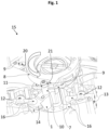
- Figure 1 illustrates a perspective view of components for an on-load tap changer for a transformer which allows for variable turn ratios to be selected in distinct steps without a supply interruption during a tap change.
- the on-load tap changer comprises a contact system 15 that enables a stable and reliable electrical connecting mechanism and contributes to low wear and low stress of interacting components.
- the contact system 15 comprises two fixed contact units 12 each comprising two electrical contact elements 16 that are formed as rounded contact pins of contact fingers, respectively.
- the contact system 15 further comprises a movable contact unit 1 with an electrical contact element 14 that is formed ambushed or wedge-shaped sectionally at least and that is configured to make electric connection to the contact elements 16 of the respective fixed contact unit 12.
- the contact element 14 of the movable contact unit 1 is engaged between the contact elements 16 and thus in contact with the fixed contact unit 12 on the left side.
- the two fingerlike contact elements 16 are formed spaced apart from each other with a given distance in between that is formed in coordination with a thickness of the wedge-shaped contact element 14 of the rotatable contact unit 1.
- the contact system 15 further comprises a driving element 8 that is formed as a control disc with two drivers 9 formed as working teeth facing each other.
- the driving element 8 is coupled or temporarily coupled to the movable contact unit 1 by means of one of the drivers 9 and an axle 10 that is connected to the movable contact unit 1.
- a roller element 11 is arranged at a top of the axle 10 and rollable around a longitudinal axis L2 of the axle 10 and enables a low friction contact to the respective drivers 9 upon contacts.
- the contact system 15 further comprises a current transmission element 3 that is formed as a cylindrical contact thumb and that is electrically coupled to the movable contact unit 1 such that the current transmission element 3 is radially closer to the rotation axis R than the contact elements 16 of the fixed contact units 12.
- the contact elements 16 of the fixed contact units 12 are arranged radially outside and the current transmission element 3 is arranged radially inside with respect to the rotation axis R (see also Fig. 2 ).
- the driving element 8 can radially extend further than the current transmission element 3 such that it overlaps the current transmission element 3 in a projected manner.
- the contact elements 16 of the fixed contact units 12 can be arranged spaced apart from the driving element 8 with respect to a top view. Such a configuration close to a driving cam or shaft allows for a set up with reduced dimensions compared to conventional systems.
- Figure 2 shows a cross section view of components of the contact system 15 and in particular the arrangement of the current transmission element 3 with respect to the movable contact unit 1.
- the contact system 15 further comprises a fixed axis element 2 that is coupled to the movable contact unit 1 and that is sleeve-shaped such that axis element 2 limits an inner recess.
- the current transmission element 3 and a spring element 4 are arranged in the inner recess of the axis element 2 such that the spring element 4 presses the current transmission element 3 towards the movable contact unit 1.
- the current transmission element 3 comprises a curved upper contact surface 19 that is in contact with a flat lower contact surface 17 of the movable contact unit 1.
- the current transmission element 3 comprises as an elongated cylindrical element a longitudinal axis L1 and is arranged in the center of rotation of the movable contact unit 1 such that the longitudinal axis L1 of the cylindrical current transmission element 3 basically coincides with the rotations axis R of the movable contact unit 1.
- a securing element 5 is attached to the current transmission element 3 and extends into the groove 6 in order to counteract an unwanted rotational movement of the current transmission element 3 around its longitudinal axis L1 or the rotation axis R, respectively.
- the securing element 5 is formed as a riveted pin extending perpendicular from an outer surface 18 of the current transmission element 3. A translation of the securing element 5 in up-and-down direction along the rotation axis R is allowed to a certain extent.
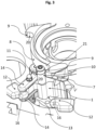
- FIG. 3 shows a further embodiment of the contact system 15, wherein the formations of the fixed contact unit 12 and the moveable contact unit 1 are substantially swapped in comparison with the embodiment as illustrated in Fig. 1 .
- the inner movable contact unit 1 comprises two electrical contact elements 14 formed as rounded contact fingers which realize a grip-like pair of contact elements.
- the electrical contact elements 14 are configured to rotate and to engage with one of the fixed contact elements 16 of the corresponding fixed contact unit 12 such that the contact elements 14 are in contact with an upper and/or a lower surface of the respective contact element 16.
- the fixed contact elements 16 are formed as rounded contact plates at opposite sides with respect to the movement of the contact unit 1 in circumferential direction.
- Such a configuration of the contact units 1, 12 and the contact system 15 can enable a clear and simple structure which may contribute to a reduction of manufacturing and assembling costs.
Landscapes
- Physics & Mathematics (AREA)
- Electromagnetism (AREA)
- Contacts (AREA)
- Rotary Switch, Piano Key Switch, And Lever Switch (AREA)
- Driving Mechanisms And Operating Circuits Of Arc-Extinguishing High-Tension Switches (AREA)
Abstract
A contact system (15) for an on-load tap changer comprises:
- a plurality of fixed contact units (12) each with at least one electrical contact element (16);
- a movable contact unit (1) with at least one electrical contact element (14) that is configured to make electric connection to a contact element (16) of a respective fixed contact unit (12);
- a driving element (8) that is at least temporarily coupled to the movable contact unit (1) and that is configured to rotationally drive the movable contact unit (1) around a rotation axis (R) towards a fixed contact element (16) of a respective fixed contact unit (12); and
- a current transmission element (3) that is electrically coupled to the movable contact unit (1) such that the current transmission element (3) is radially closer to the rotation axis (R) than the contact elements (16) of the fixed contact units.
- a plurality of fixed contact units (12) each with at least one electrical contact element (16);
- a movable contact unit (1) with at least one electrical contact element (14) that is configured to make electric connection to a contact element (16) of a respective fixed contact unit (12);
- a driving element (8) that is at least temporarily coupled to the movable contact unit (1) and that is configured to rotationally drive the movable contact unit (1) around a rotation axis (R) towards a fixed contact element (16) of a respective fixed contact unit (12); and
- a current transmission element (3) that is electrically coupled to the movable contact unit (1) such that the current transmission element (3) is radially closer to the rotation axis (R) than the contact elements (16) of the fixed contact units.
Description
- The present disclosure is related to a contact system for an on-load tap changer and a corresponding on-load tap changer.
- Tap changers realize a mechanism in transformers which allows for variable turn ratios to be selected in distinct steps, for example. In view of movable and stationary electrically engaging contacts it is a challenge to provide a stable and reliable mechanism with low wear and stress.
- Thus, it is an object to provide a contact system for an on-load tap changer that allows for a stable and reliable mechanism and contributes to low wear and low stress of interacting components.
- According to an embodiment, a contact system for a tap changer, e.g. an on-load tap changer, comprises a plurality of fixed contact units and a movable contact unit. Each fixed contact unit has at least one electrical contact element. The movable contact unit also has at least one electrical contact element that is configured to make electric connection to one contact element of an associated fixed contact unit. The contact system further comprises a driving element that is coupled or temporarily coupled to the movable contact unit in order to rotationally drive the movable contact unit around a rotation axis towards one of the fixed contact element of a respective fixed contact unit. The contact system further comprises a current transmission element that is electrically coupled to the movable contact unit such that the current transmission element is radially closer to the rotation axis than the contact elements of the fixed contact units.
- By use of the described contact system an electric connection mechanism for an on-load tap changer is feasible that allows for a stable and reliable functioning and that contributes to low wear and low stress of interacting components.
- The movable contact unit is at least rotatable but may additionally be movable along a given translation direction. The fixed contact units are fixed relatively to the movable contact unit. Alternatively, the fixed contact units may be also movable in a predetermined manner. For example, there are two fixed contact units which realize stationary electrical contacts and the movable contact unit is moved to one or the other fixed contact to provide a respective voltage transfer in a selector of a power diverter switch for an on-load tap changer.
- According to an embodiment of the contact system, the current transmission element is arranged in an area of the rotation axis of the movable contact unit such that the rotations axis contacts or penetrates the current transmission element in a projected manner. The current transmission element is therefore arranged in a center or at least close to the center of the contact system or of the rotation and enables to reduce the set up dimensions of the contact system compared to conventional concepts. The contact system may realize a resistor contact system acting at an end of a switching operation of a vacuum-type on-load tap changer with current carrying at the center of rotation.
- According to a further embodiment, the contact system comprises a fixed axis element that is coupled to the movable contact unit and that is sleeve-shaped such that axis element limits an inner recess. The current transmission element is arranged in the inner recess of the axis element and contacts the movable contact unit. Such a configuration allows a particularly stable and secure arrangement to be set up and further enables reliable current and power transmission.
- According to a further embodiment, the contact system comprises a spring element that is arranged inside the inner recess of the axis element and that is coupled to the current transmission element such that it presses the current transmission element towards the movable contact unit. The spring element provides a spring force that acts on the current transmission element and drives it into a predetermined direction. Consequently, a particularly stable and reliable contact between the current transmission element and the movable contact can be enabled.
- It is a recognition of the present disclosure that usual designs for contact concepts of selector mechanisms in on-load tap changers comprise switching schemes with diverter switches with vacuum interrupters, wherein fast-acting main and resistor contact systems are used. The main contact system is actuated in the middle of a stroke of the symmetrically rotating back and forth main shaft. This allows for a simple set up to be accomplished, for example with a simple Geneva gear. However, such a contact concepts is actuated at both ends of a set angle of rotation of the shaft. A reliable performance is more difficult and is achieved by additional drive parts and it is a challenge to enable current transmission of rotating contacts to stationary ones. This might be set up by flexible connections or a plurality of arm movable contacts, one side of which rubs permanently on a fixed contact. Accordingly, there is a relatively large space required and moreover friction and therefore wear and fatigue of the material of the flexible connections occur sooner or later.
- The described contact system enables to counteract the aforementioned difficulties due to the specific set up of the movable contact unit and the fixed contact units and the implementation of the current transmission element relatively close to the centre of rotation. A set up is feasible with a compact and simple design of rotatable fast-motion resistor contact system which enables reliable switching operation acting at an end of a stroke of a main driving shaft of a tap changer, for example, wherein a current transmission takes place at or close to the center of rotation of the movable contact unit.
- According to a further embodiment of the contact system, a groove is limited by the axis element and the movable contact unit, and wherein a securing element is attached to the current transmission element and extends into the groove such that the securing element counteracts a rotational movement of the current transmission element. For example, the securing element can be formed as a riveted pin that extends from an outer surface of the current transmission element. The securing element and the groove are preferably configured in coordination with each other geometrically such that an unwanted rotation of the current transmission element is blocked but a slight movement along the rotation axis may be allowed.
- According to a further embodiment of the contact system, the current transmission element comprises a domed convex surface that is in contact with a contact surface of the movable contact unit. For example, the contact surface of the movable contact unit is flat and the one of the current transmission element is convex and thus there is mathematically only one point of contact. However, the area of contact is relatively small at least and thus there is relatively low friction, mechanical stress and wear of the interaction components.
- According to a further embodiment of the contact system, the current transmission element is substantially formed rotation symmetrically, e.g. as an elongated cylindrical contact member, and is arranged in the center of rotation of the movable contact unit such that a longitudinal axis of the cylindrical contact member coincides with the rotations axis of the movable contact unit.
- According to a further embodiment of the contact system, the fixed contact units each comprise two or more contact elements formed spaced apart from each other with a given distance in between that is formed in coordination with a thickness of the contact element of the movable contact unit. For example, the contact elements of the fixed contact units each are formed as rounded pin elements or fingers and the contact element of the movable contact unit is formed ambushed or wedge-shaped sectionally at least. Such a configuration allows to engage a stable and low friction contact of the contact elements.
- According to a further embodiment of the contact system, the driving element is formed substantially rotation symmetrically, e.g. as a control disc, and comprises two drivers that formed spaced apart from each other with a given circumferential distance in between. The contact system can further comprise an axle that is coupled to the movable contact unit and that is arranged circumferentially between the drivers configured to interact with the drivers such that when the control disc rotates one driver is moved towards the axle and contacts the axle and drives the axle towards one of the fixed contact units. The circumferential distance between the drivers is preferably formed in coordination with a circumferential distance between two adjacent fixed contact units such that the driving element and its drivers moves a given stroke and a predetermined angle of rotation. The drivers act as a respective working tooth configured to interact with the axle which may realize kind of a contact thumb. The driving element and the drivers may travel a certain idle angular distance before one of the driver contacts the axle and pushes the axle and the movable contact towards one of the fixed contact unit to make the intended electrical connection for power switching.
- According to a further embodiment of the contact system, the drivers and the axle each comprise a curved contact surface facing each other and configured in coordination with each other. Such rounded surfaces can contribute to secure and reliable contacting with low friction. Additionally, the contact system can comprise a roller element that is arranged rotatably at the axle around a longitudinal axis of the axle and that is configured to get in contact with one of the drivers when the movable contact unit is to be rotated. Such a rollable contact between the axle and the drivers can enable a particularly low friction contact during rotation of the movable contact unit.
- According to an embodiment an on-load tap changer for setting a gear ratio comprises a central shaft that forms a drive and an embodiment of the described contact system. The driving element of the contact system is coupled to the central shaft. As a result of that the on-load tap changer comprises an embodiment of the contact ring unit as described above, features and characteristics of the contact ring unit are also disclosed with respect to the on-load tap changer and vice versa.
- The described configurations of the contact system and the corresponding tap changer each enable a simple fast-acting resistor contact system with at least some of the following features and/or advantageous:
- 1. A fast-acting resistor contact system (e.g. with a circumferential velocity in the ms-range between two adjacent fixed contacts) includes a rotating contact unit which, at both ends of its stroke, engages with corresponding fixed pin pairs of fixed contacts. The movable contact unit can be driven by a drive disc rotating symmetrically in two directions which is located on a central shaft of a diverter switch. In its movement, the disc can travel a certain idle angular distance before a working tooth drives a contact thumb provided for this purpose, fixed firmly on the movable contact unit.
- 2. A further contact thumb that can form the current transmission element is preferably located in the axis of rotation of the movable contact unit, and a rounded tip of this contact thumb contacts a flat surface of the movable contact unit. As a tangential velocity is theoretically zero at the point contact or the point of rotation, friction and wear are negligibly small in practice. This eliminates the harmful effects of friction on the speed of the contact system and further allows to achieve a beneficial compact design.
- Exemplary embodiments are explained in the following with the aid of schematic drawings and reference numbers. The figures show:
-
Figure 1 an embodiment of a contact system for an on-load tap changer in a perspective view, -
Figure 2 a cross section view of components of the contact system offigure 1 and -
Figure 3 a further embodiment of the contact system for an on-load tap changer in a perspective view. - The accompanying figures are included to provide a further understanding. Identical reference numbers designate elements or components with identical functions. In so far as elements or components correspond to one another in terms of their function in different figures, the description thereof is not repeated for each of the following figures. For the sake of clarity elements might not appear with corresponding reference symbols in all figures, possibly.
-
Figure 1 illustrates a perspective view of components for an on-load tap changer for a transformer which allows for variable turn ratios to be selected in distinct steps without a supply interruption during a tap change. The on-load tap changer comprises acontact system 15 that enables a stable and reliable electrical connecting mechanism and contributes to low wear and low stress of interacting components. - The
contact system 15 comprises two fixedcontact units 12 each comprising twoelectrical contact elements 16 that are formed as rounded contact pins of contact fingers, respectively. Thecontact system 15 further comprises amovable contact unit 1 with anelectrical contact element 14 that is formed ambushed or wedge-shaped sectionally at least and that is configured to make electric connection to thecontact elements 16 of the respective fixedcontact unit 12. - According to
figure 1 thecontact element 14 of themovable contact unit 1 is engaged between thecontact elements 16 and thus in contact with the fixedcontact unit 12 on the left side. The twofingerlike contact elements 16 are formed spaced apart from each other with a given distance in between that is formed in coordination with a thickness of the wedge-shapedcontact element 14 of therotatable contact unit 1. - The
contact system 15 further comprises a drivingelement 8 that is formed as a control disc with twodrivers 9 formed as working teeth facing each other. The drivingelement 8 is coupled or temporarily coupled to themovable contact unit 1 by means of one of thedrivers 9 and anaxle 10 that is connected to themovable contact unit 1. Aroller element 11 is arranged at a top of theaxle 10 and rollable around a longitudinal axis L2 of theaxle 10 and enables a low friction contact to therespective drivers 9 upon contacts. - The
axle 10 can be securely arranged inside a recess penetrate the movable contact unit 1 (seeFig. 2 ). The drivingelement 8 is configured to rotationally drive themovable contact unit 1 around a rotation axis R in both circumferential directions towards the respective fixedcontact element 16 of the associated fixedcontact unit 12. According tofigure 1 , the drivingelement 8 would turn anticlockwise (as illustrated by an arrow) to switch thecontact element 16 from the left fixedcontact unit 12 to the rightfixed contact unit 12. - The
contact system 15 further comprises acurrent transmission element 3 that is formed as a cylindrical contact thumb and that is electrically coupled to themovable contact unit 1 such that thecurrent transmission element 3 is radially closer to the rotation axis R than thecontact elements 16 of the fixedcontact units 12. In other words, thecontact elements 16 of the fixedcontact units 12 are arranged radially outside and thecurrent transmission element 3 is arranged radially inside with respect to the rotation axis R (see alsoFig. 2 ). In other words, with respect to a top view, the drivingelement 8 can radially extend further than thecurrent transmission element 3 such that it overlaps thecurrent transmission element 3 in a projected manner. Thecontact elements 16 of the fixedcontact units 12 can be arranged spaced apart from the drivingelement 8 with respect to a top view. Such a configuration close to a driving cam or shaft allows for a set up with reduced dimensions compared to conventional systems. -
Figure 2 shows a cross section view of components of thecontact system 15 and in particular the arrangement of thecurrent transmission element 3 with respect to themovable contact unit 1. Thecontact system 15 further comprises a fixedaxis element 2 that is coupled to themovable contact unit 1 and that is sleeve-shaped such thataxis element 2 limits an inner recess. Thecurrent transmission element 3 and aspring element 4 are arranged in the inner recess of theaxis element 2 such that thespring element 4 presses thecurrent transmission element 3 towards themovable contact unit 1. Thecurrent transmission element 3 comprises a curvedupper contact surface 19 that is in contact with a flatlower contact surface 17 of themovable contact unit 1. Thecurrent transmission element 3 comprises as an elongated cylindrical element a longitudinal axis L1 and is arranged in the center of rotation of themovable contact unit 1 such that the longitudinal axis L1 of the cylindricalcurrent transmission element 3 basically coincides with the rotations axis R of themovable contact unit 1. - There is further a groove formed or limited by the
axis element 2 and themovable contact unit 1, and a securingelement 5 is attached to thecurrent transmission element 3 and extends into thegroove 6 in order to counteract an unwanted rotational movement of thecurrent transmission element 3 around its longitudinal axis L1 or the rotation axis R, respectively. The securingelement 5 is formed as a riveted pin extending perpendicular from anouter surface 18 of thecurrent transmission element 3. A translation of the securingelement 5 in up-and-down direction along the rotation axis R is allowed to a certain extent. - The described and illustrated embodiments realize a fast-acting
resistor contact system 15 with themovable contact 1 that is rotatable about a fixedaxis 2. Thecurrent transmission element 3 comprises a rounded tip and is inserted in a bore of theaxle 2, which is pressed on its underside by thespring element 4 which presses thecurrent transmission element 3 against theflat surface 17 of themovable contact unit 1. - The
current transmission element 3 is secured against turning by means of the securingelement 5 which can only move axially in thegroove 6 with respect to the longitudinal axis L1 or the rotation axis R. From a lower end of the current transmission element 3 a wire can be brought out which makes the electrical connection. Astationary support element 7 is configured to counteract the spring force and is rounded similarly to thecurrent transmission element 3 such that its tip also being located at the pivot point (seeFig. 2 ). - The
movable contact unit 1 is driven by the control disc or the drivingelement 8, which can be fixed on a main driving shaft of a diverter switch of the on-load tap changer. This drivingelement 8 comprises thedrivers 9 forming working teeth which, when the drivingelement 8 is rotating, contact theroller element 11 at theaxle 10. Theaxle 10 is clamped to themovable contact unit 1 and is rotated until it is engaging in between one pair ofcontact elements 16 of the respective fixedcontact unit 12. Acontact spring 13 pushes outer ends of thecontact elements 16 away from each other such that the rounded inner ends of thecontact elements 16 are pushed towards each other to enable a secure, stable and reliable contact to thecontact element 14 that is pushed or inserted in between. The switching operation takes place at both ends of the angular travel of the drivingelement 8 and the angle between the two steering teeth ordrivers 9 is preferably set with a required idle travel. -
Figure 3 shows a further embodiment of thecontact system 15, wherein the formations of the fixedcontact unit 12 and themoveable contact unit 1 are substantially swapped in comparison with the embodiment as illustrated inFig. 1 . The innermovable contact unit 1 comprises twoelectrical contact elements 14 formed as rounded contact fingers which realize a grip-like pair of contact elements. Theelectrical contact elements 14 are configured to rotate and to engage with one of the fixedcontact elements 16 of the corresponding fixedcontact unit 12 such that thecontact elements 14 are in contact with an upper and/or a lower surface of therespective contact element 16. The fixedcontact elements 16 are formed as rounded contact plates at opposite sides with respect to the movement of thecontact unit 1 in circumferential direction. Such a configuration of thecontact units contact system 15 can enable a clear and simple structure which may contribute to a reduction of manufacturing and assembling costs. - The embodiments shown in the
figures 1 to 3 as stated represent exemplary embodiments of animproved contact system 15 and a corresponding on-load tap changer; therefore, they do not constitute a complete list of all embodiments according to possible arrangements. Actual arrangements of thecontact system 15 and/or the on-load tap changer may vary from the embodiments shown in the figures. -
- 1
- movable contact unit
- 2
- fixed axis element
- 3
- current transmission element
- 4
- spring element
- 5
- securing element
- 6
- groove
- 7
- stationary support element
- 8
- driving element / control disc
- 9
- driver
- 10
- axle
- 11
- roller element
- 12
- fixed contact unit
- 13
- contact spring
- 14
- movable contact element
- 15
- contact system
- 16
- fixed contact elements
- 17
- contact surface of the movable contact unit
- 18
- outer side surface of the movable contact unit
- 19
- contact surface of the current transmission element
- 20
- contact surface of the driver
- 21
- contact surface of the axle / roller element
- L1
- longitudinal axis of the axle
- L2
- longitudinal axis of the axle
- R
- rotation axis of the movable contact unit
Claims (14)
- Contact system (15) for an on-load tap changer, comprising:- a plurality of fixed contact units (12) each with at least one electrical contact element (16),- a movable contact unit (1) with at least one electrical contact element (14) that is configured to make electric connection to a contact element (16) of a respective fixed contact unit (12),- a driving element (8) that is at least temporarily coupled to the movable contact unit (1) and configured to rotationally drive the movable contact unit (1) around a rotation axis (R) towards a fixed contact element (16) of a respective fixed contact unit (12), and- a current transmission element (3) that is electrically coupled to the movable contact unit (1) such that the current transmission element (3) is radially closer to the rotation axis (R) than the contact elements (16) of the fixed contact units (12).
- Contact system (15) according to claim 1, wherein the current transmission element (3) is arranged in an area of the rotation axis (R) of the movable contact unit (1) such that the rotations axis (R) contacts or penetrates the current transmission element (3) in a projected manner.
- Contact system (15) according to any of the proceeding claims, comprising:
a fixed axis element (2) that is coupled to the movable contact unit (1) and that is sleeve-shaped such that axis element (2) limits an inner recess, wherein the current transmission element (3) is arranged in the inner recess of the axis element (2) such that is contacts the movable contact unit (1). - Contact system (15) according to claim 3, comprising:
a spring element (4) that is arranged inside the inner recess of the axis element (2) and coupled to the current transmission element (3) such that it presses the current transmission element (3) towards the movable contact unit (1) . - Contact system (15) according to claim 3 or 4, wherein a groove (6) is limited by the axis element (2) and the movable contact unit (1), and wherein a securing element (5) is attached to the current transmission element (3) and extends into the groove (6) such that the securing element (5) counteracts a rotational movement of the current transmission element (3).
- Contact system (15) according to claim 5, wherein the securing element (5) is formed as a riveted pin that extends from an outer surface (18) of the current transmission element (3).
- Contact system (15) according to any of the proceeding claims, wherein the current transmission element (3) comprises a domed convex contact surface (19) that is in contact with a contact surface (17) of the movable contact unit (1).
- Contact system (15) according to any of the proceeding claims, wherein the current transmission element (3) is formed as an elongated cylindrical contact member and is arranged in the center of rotation of the movable contact unit (1) such that a longitudinal axis (L1) of the cylindrical contact member coincides with the rotations axis (R) of the movable contact unit (1).
- Contact system (15) according to any of the proceeding claims, wherein the fixed contact units (12) each comprise two or more contact elements (16) formed spaced apart from each other with a given distance in between that is formed in coordination with a thickness of the contact element (14) of the movable contact unit (1).
- Contact system (15) according to claim 9, wherein the contact elements (16) of the fixed contact units (12) each are formed as rounded pin elements and wherein the contact element (14) of the movable contact unit (1) is formed ambushed or wedge-shaped sectionally at least.
- Contact system (15) according to any of the proceeding claims, wherein the driving element (8) is formed as a control disc and comprises two drivers (9) that are formed spaced apart from each other with a given circumferential distance in between, and wherein an axle (10) is coupled to the movable contact unit (1) that is arranged circumferentially between the drivers (9) and that is configured to interact with the drivers (9) such that when the control disc rotates one driver (9) is moved towards the axle (10), contacts the axle (10) and drives the axle (10) towards one of the fixed contact units (12).
- Contact system (15) according to claim 11, wherein the drivers (9) and the axle (10) each comprise a curved contact surface (20, 21) facing each other and configured in coordination with each other.
- Contact system (15) according to claim 11 or 12, comprising:
a roller element (11) that is arranged rotatably at the axle (10) around a longitudinal axis (L2) of the axle (10) and that is configured to get in contact with one of the drivers (9) when the movable contact unit (1) is to be rotated. - On-load tap changer, comprising:- a central shaft that is configured to provide a drive,
and- a contact system (15) according to any of the preceding claims, wherein the driving element (8) of the contact system (15) is coupled to the central shaft.
Priority Applications (4)
| Application Number | Priority Date | Filing Date | Title |
|---|---|---|---|
| EP23194602.1A EP4517791A1 (en) | 2023-08-31 | 2023-08-31 | Contact system for an on-load tap changer and on-load tap changer |
| PCT/EP2024/069545 WO2025045426A1 (en) | 2023-08-31 | 2024-07-10 | Contact system for an on-load tap changer and on-load tap changer |
| KR1020267006284A KR20260045858A (en) | 2023-08-31 | 2024-07-10 | Contact system for a load-on-load tap changer and a load-on-load tap changer |
| CN202480054826.8A CN121753126A (en) | 2023-08-31 | 2024-07-10 | Contact system for an on-load tap-changer and on-load tap-changer |
Applications Claiming Priority (1)
| Application Number | Priority Date | Filing Date | Title |
|---|---|---|---|
| EP23194602.1A EP4517791A1 (en) | 2023-08-31 | 2023-08-31 | Contact system for an on-load tap changer and on-load tap changer |
Publications (1)
| Publication Number | Publication Date |
|---|---|
| EP4517791A1 true EP4517791A1 (en) | 2025-03-05 |
Family
ID=87889682
Family Applications (1)
| Application Number | Title | Priority Date | Filing Date |
|---|---|---|---|
| EP23194602.1A Pending EP4517791A1 (en) | 2023-08-31 | 2023-08-31 | Contact system for an on-load tap changer and on-load tap changer |
Country Status (4)
| Country | Link |
|---|---|
| EP (1) | EP4517791A1 (en) |
| KR (1) | KR20260045858A (en) |
| CN (1) | CN121753126A (en) |
| WO (1) | WO2025045426A1 (en) |
Citations (5)
| Publication number | Priority date | Publication date | Assignee | Title |
|---|---|---|---|---|
| US2660631A (en) * | 1951-08-13 | 1953-11-24 | Gen Electric | Side break disconnecting switch |
| US3742170A (en) * | 1971-09-30 | 1973-06-26 | Westinghouse Electric Corp | Loud tap changer by-pass switch contact assembly and material composition thereof |
| DE3827388A1 (en) * | 1988-08-12 | 1990-02-15 | Reinhausen Maschf Scheubeck | CYLINDRICAL STEP SELECTOR FOR STEP TRANSFORMERS WITH CONTACT RINGS HOLDED BY CONNECTING CABLES |
| US6091032A (en) * | 1997-10-04 | 2000-07-18 | Maschinenfabrik Reinhausen Gmbh | Tap changer |
| WO2012059164A1 (en) * | 2010-11-02 | 2012-05-10 | Maschinenfabrik Reinhausen Gmbh | Mechanical switch for an on-load tap changer |
Family Cites Families (1)
| Publication number | Priority date | Publication date | Assignee | Title |
|---|---|---|---|---|
| US3045090A (en) * | 1959-05-08 | 1962-07-17 | Mc Graw Edison Co | Tap changer movable contact |
-
2023
- 2023-08-31 EP EP23194602.1A patent/EP4517791A1/en active Pending
-
2024
- 2024-07-10 WO PCT/EP2024/069545 patent/WO2025045426A1/en active Pending
- 2024-07-10 KR KR1020267006284A patent/KR20260045858A/en active Pending
- 2024-07-10 CN CN202480054826.8A patent/CN121753126A/en active Pending
Patent Citations (5)
| Publication number | Priority date | Publication date | Assignee | Title |
|---|---|---|---|---|
| US2660631A (en) * | 1951-08-13 | 1953-11-24 | Gen Electric | Side break disconnecting switch |
| US3742170A (en) * | 1971-09-30 | 1973-06-26 | Westinghouse Electric Corp | Loud tap changer by-pass switch contact assembly and material composition thereof |
| DE3827388A1 (en) * | 1988-08-12 | 1990-02-15 | Reinhausen Maschf Scheubeck | CYLINDRICAL STEP SELECTOR FOR STEP TRANSFORMERS WITH CONTACT RINGS HOLDED BY CONNECTING CABLES |
| US6091032A (en) * | 1997-10-04 | 2000-07-18 | Maschinenfabrik Reinhausen Gmbh | Tap changer |
| WO2012059164A1 (en) * | 2010-11-02 | 2012-05-10 | Maschinenfabrik Reinhausen Gmbh | Mechanical switch for an on-load tap changer |
Also Published As
| Publication number | Publication date |
|---|---|
| WO2025045426A1 (en) | 2025-03-06 |
| CN121753126A (en) | 2026-03-27 |
| KR20260045858A (en) | 2026-04-03 |
Similar Documents
| Publication | Publication Date | Title |
|---|---|---|
| JP4235290B2 (en) | Load tap changer | |
| US11004622B2 (en) | On-load tap changer | |
| JP5286610B2 (en) | Tap changer | |
| KR102642659B1 (en) | Switching systems for on-load tap-changers, on-load tap-changers and methods for switching tap connections in on-load tap-changers | |
| RU2139588C1 (en) | Load switch to change over stage of transformer windings | |
| WO2025045426A1 (en) | Contact system for an on-load tap changer and on-load tap changer | |
| KR102642658B1 (en) | Switching systems for on-load tap-changers, on-load tap-changers and methods for switching tap connections in on-load tap-changers | |
| CN203250656U (en) | Mechanical switch | |
| JP7480015B2 (en) | On-load tap changer tap selector | |
| RU2446501C2 (en) | Driving system for electric main contact drive | |
| KR102628580B1 (en) | Switching system for on-load tap-changer, switching method of on-load tap-changer and tap connection of on-load tap-changer | |
| EP4044206B1 (en) | Contact unit and contact system for an on-load tap changer and on-load tap changer | |
| AU2020381819A1 (en) | On-load tap changer | |
| CN102315029B (en) | For the method and system of the preselector in shunting switch | |
| JPH0254611B2 (en) | ||
| JP7362914B2 (en) | Energy storage mechanism of on-load tap changer and on-load tap changer | |
| JP4087168B2 (en) | Vacuum valve type load tap changer | |
| WO2025256881A1 (en) | Contact system for an on-load tap changer and on-load tap changer | |
| US3852553A (en) | Vacuum switch with toggle assembly operating mechanism | |
| JP7785656B2 (en) | Tap selector moving contact drive mechanism | |
| EP4517794A1 (en) | Contact ring unit for a tap changer and tap changer | |
| WO2019064003A1 (en) | On-load tap-changer | |
| JP3663054B2 (en) | Tap switching device for winding of electrical equipment | |
| WO2025209755A1 (en) | Static contact unit, contact system and tap changer | |
| JP4064474B2 (en) | Geared motor with stop positioning mechanism |
Legal Events
| Date | Code | Title | Description |
|---|---|---|---|
| PUAI | Public reference made under article 153(3) epc to a published international application that has entered the european phase |
Free format text: ORIGINAL CODE: 0009012 |
|
| STAA | Information on the status of an ep patent application or granted ep patent |
Free format text: STATUS: THE APPLICATION HAS BEEN PUBLISHED |
|
| AK | Designated contracting states |
Kind code of ref document: A1 Designated state(s): AL AT BE BG CH CY CZ DE DK EE ES FI FR GB GR HR HU IE IS IT LI LT LU LV MC ME MK MT NL NO PL PT RO RS SE SI SK SM TR |
|
| STAA | Information on the status of an ep patent application or granted ep patent |
Free format text: STATUS: REQUEST FOR EXAMINATION WAS MADE |
|
| 17P | Request for examination filed |
Effective date: 20250723 |