EP4517654A2 - Umwandlung biologischer bilder unter verwendung von maschinenlernmodellen - Google Patents
Umwandlung biologischer bilder unter verwendung von maschinenlernmodellen Download PDFInfo
- Publication number
- EP4517654A2 EP4517654A2 EP24221939.2A EP24221939A EP4517654A2 EP 4517654 A2 EP4517654 A2 EP 4517654A2 EP 24221939 A EP24221939 A EP 24221939A EP 4517654 A2 EP4517654 A2 EP 4517654A2
- Authority
- EP
- European Patent Office
- Prior art keywords
- images
- image
- type
- training
- learning model
- Prior art date
- Legal status (The legal status is an assumption and is not a legal conclusion. Google has not performed a legal analysis and makes no representation as to the accuracy of the status listed.)
- Pending
Links
Images


Classifications
-
- G—PHYSICS
- G06—COMPUTING OR CALCULATING; COUNTING
- G06V—IMAGE OR VIDEO RECOGNITION OR UNDERSTANDING
- G06V20/00—Scenes; Scene-specific elements
- G06V20/60—Type of objects
- G06V20/69—Microscopic objects, e.g. biological cells or cellular parts
-
- G—PHYSICS
- G06—COMPUTING OR CALCULATING; COUNTING
- G06T—IMAGE DATA PROCESSING OR GENERATION, IN GENERAL
- G06T11/00—2D [Two Dimensional] image generation
- G06T11/60—Editing figures and text; Combining figures or text
-
- G—PHYSICS
- G06—COMPUTING OR CALCULATING; COUNTING
- G06F—ELECTRIC DIGITAL DATA PROCESSING
- G06F18/00—Pattern recognition
- G06F18/20—Analysing
- G06F18/21—Design or setup of recognition systems or techniques; Extraction of features in feature space; Blind source separation
- G06F18/214—Generating training patterns; Bootstrap methods, e.g. bagging or boosting
-
- G—PHYSICS
- G06—COMPUTING OR CALCULATING; COUNTING
- G06F—ELECTRIC DIGITAL DATA PROCESSING
- G06F18/00—Pattern recognition
- G06F18/20—Analysing
- G06F18/24—Classification techniques
- G06F18/243—Classification techniques relating to the number of classes
- G06F18/2431—Multiple classes
-
- G—PHYSICS
- G06—COMPUTING OR CALCULATING; COUNTING
- G06N—COMPUTING ARRANGEMENTS BASED ON SPECIFIC COMPUTATIONAL MODELS
- G06N20/00—Machine learning
-
- G—PHYSICS
- G06—COMPUTING OR CALCULATING; COUNTING
- G06N—COMPUTING ARRANGEMENTS BASED ON SPECIFIC COMPUTATIONAL MODELS
- G06N3/00—Computing arrangements based on biological models
- G06N3/02—Neural networks
- G06N3/04—Architecture, e.g. interconnection topology
- G06N3/045—Combinations of networks
-
- G—PHYSICS
- G06—COMPUTING OR CALCULATING; COUNTING
- G06N—COMPUTING ARRANGEMENTS BASED ON SPECIFIC COMPUTATIONAL MODELS
- G06N3/00—Computing arrangements based on biological models
- G06N3/02—Neural networks
- G06N3/04—Architecture, e.g. interconnection topology
- G06N3/0464—Convolutional networks [CNN, ConvNet]
-
- G—PHYSICS
- G06—COMPUTING OR CALCULATING; COUNTING
- G06N—COMPUTING ARRANGEMENTS BASED ON SPECIFIC COMPUTATIONAL MODELS
- G06N3/00—Computing arrangements based on biological models
- G06N3/02—Neural networks
- G06N3/04—Architecture, e.g. interconnection topology
- G06N3/047—Probabilistic or stochastic networks
-
- G—PHYSICS
- G06—COMPUTING OR CALCULATING; COUNTING
- G06N—COMPUTING ARRANGEMENTS BASED ON SPECIFIC COMPUTATIONAL MODELS
- G06N3/00—Computing arrangements based on biological models
- G06N3/02—Neural networks
- G06N3/04—Architecture, e.g. interconnection topology
- G06N3/0475—Generative networks
-
- G—PHYSICS
- G06—COMPUTING OR CALCULATING; COUNTING
- G06N—COMPUTING ARRANGEMENTS BASED ON SPECIFIC COMPUTATIONAL MODELS
- G06N3/00—Computing arrangements based on biological models
- G06N3/02—Neural networks
- G06N3/08—Learning methods
- G06N3/084—Backpropagation, e.g. using gradient descent
-
- G—PHYSICS
- G06—COMPUTING OR CALCULATING; COUNTING
- G06N—COMPUTING ARRANGEMENTS BASED ON SPECIFIC COMPUTATIONAL MODELS
- G06N3/00—Computing arrangements based on biological models
- G06N3/02—Neural networks
- G06N3/08—Learning methods
- G06N3/088—Non-supervised learning, e.g. competitive learning
-
- G—PHYSICS
- G06—COMPUTING OR CALCULATING; COUNTING
- G06N—COMPUTING ARRANGEMENTS BASED ON SPECIFIC COMPUTATIONAL MODELS
- G06N3/00—Computing arrangements based on biological models
- G06N3/02—Neural networks
- G06N3/08—Learning methods
- G06N3/0895—Weakly supervised learning, e.g. semi-supervised or self-supervised learning
-
- G—PHYSICS
- G06—COMPUTING OR CALCULATING; COUNTING
- G06N—COMPUTING ARRANGEMENTS BASED ON SPECIFIC COMPUTATIONAL MODELS
- G06N3/00—Computing arrangements based on biological models
- G06N3/02—Neural networks
- G06N3/08—Learning methods
- G06N3/09—Supervised learning
-
- G—PHYSICS
- G06—COMPUTING OR CALCULATING; COUNTING
- G06N—COMPUTING ARRANGEMENTS BASED ON SPECIFIC COMPUTATIONAL MODELS
- G06N3/00—Computing arrangements based on biological models
- G06N3/02—Neural networks
- G06N3/08—Learning methods
- G06N3/094—Adversarial learning
-
- G—PHYSICS
- G06—COMPUTING OR CALCULATING; COUNTING
- G06T—IMAGE DATA PROCESSING OR GENERATION, IN GENERAL
- G06T11/00—2D [Two Dimensional] image generation
-
- G—PHYSICS
- G06—COMPUTING OR CALCULATING; COUNTING
- G06T—IMAGE DATA PROCESSING OR GENERATION, IN GENERAL
- G06T5/00—Image enhancement or restoration
- G06T5/60—Image enhancement or restoration using machine learning, e.g. neural networks
-
- G—PHYSICS
- G06—COMPUTING OR CALCULATING; COUNTING
- G06T—IMAGE DATA PROCESSING OR GENERATION, IN GENERAL
- G06T7/00—Image analysis
- G06T7/0002—Inspection of images, e.g. flaw detection
- G06T7/0012—Biomedical image inspection
-
- G—PHYSICS
- G06—COMPUTING OR CALCULATING; COUNTING
- G06T—IMAGE DATA PROCESSING OR GENERATION, IN GENERAL
- G06T7/00—Image analysis
- G06T7/10—Segmentation; Edge detection
-
- G—PHYSICS
- G06—COMPUTING OR CALCULATING; COUNTING
- G06V—IMAGE OR VIDEO RECOGNITION OR UNDERSTANDING
- G06V10/00—Arrangements for image or video recognition or understanding
- G06V10/40—Extraction of image or video features
- G06V10/44—Local feature extraction by analysis of parts of the pattern, e.g. by detecting edges, contours, loops, corners, strokes or intersections; Connectivity analysis, e.g. of connected components
- G06V10/443—Local feature extraction by analysis of parts of the pattern, e.g. by detecting edges, contours, loops, corners, strokes or intersections; Connectivity analysis, e.g. of connected components by matching or filtering
- G06V10/449—Biologically inspired filters, e.g. difference of Gaussians [DoG] or Gabor filters
- G06V10/451—Biologically inspired filters, e.g. difference of Gaussians [DoG] or Gabor filters with interaction between the filter responses, e.g. cortical complex cells
- G06V10/454—Integrating the filters into a hierarchical structure, e.g. convolutional neural networks [CNN]
-
- G—PHYSICS
- G06—COMPUTING OR CALCULATING; COUNTING
- G06V—IMAGE OR VIDEO RECOGNITION OR UNDERSTANDING
- G06V10/00—Arrangements for image or video recognition or understanding
- G06V10/40—Extraction of image or video features
- G06V10/52—Scale-space analysis, e.g. wavelet analysis
-
- G—PHYSICS
- G06—COMPUTING OR CALCULATING; COUNTING
- G06V—IMAGE OR VIDEO RECOGNITION OR UNDERSTANDING
- G06V10/00—Arrangements for image or video recognition or understanding
- G06V10/40—Extraction of image or video features
- G06V10/60—Extraction of image or video features relating to illumination properties, e.g. using a reflectance or lighting model
-
- G—PHYSICS
- G06—COMPUTING OR CALCULATING; COUNTING
- G06V—IMAGE OR VIDEO RECOGNITION OR UNDERSTANDING
- G06V10/00—Arrangements for image or video recognition or understanding
- G06V10/70—Arrangements for image or video recognition or understanding using pattern recognition or machine learning
- G06V10/77—Processing image or video features in feature spaces; using data integration or data reduction, e.g. principal component analysis [PCA] or independent component analysis [ICA] or self-organising maps [SOM]; Blind source separation
- G06V10/774—Generating sets of training patterns; Bootstrap methods, e.g. bagging or boosting
-
- G—PHYSICS
- G06—COMPUTING OR CALCULATING; COUNTING
- G06V—IMAGE OR VIDEO RECOGNITION OR UNDERSTANDING
- G06V10/00—Arrangements for image or video recognition or understanding
- G06V10/70—Arrangements for image or video recognition or understanding using pattern recognition or machine learning
- G06V10/77—Processing image or video features in feature spaces; using data integration or data reduction, e.g. principal component analysis [PCA] or independent component analysis [ICA] or self-organising maps [SOM]; Blind source separation
- G06V10/80—Fusion, i.e. combining data from various sources at the sensor level, preprocessing level, feature extraction level or classification level
-
- G—PHYSICS
- G06—COMPUTING OR CALCULATING; COUNTING
- G06V—IMAGE OR VIDEO RECOGNITION OR UNDERSTANDING
- G06V10/00—Arrangements for image or video recognition or understanding
- G06V10/70—Arrangements for image or video recognition or understanding using pattern recognition or machine learning
- G06V10/82—Arrangements for image or video recognition or understanding using pattern recognition or machine learning using neural networks
-
- A—HUMAN NECESSITIES
- A61—MEDICAL OR VETERINARY SCIENCE; HYGIENE
- A61B—DIAGNOSIS; SURGERY; IDENTIFICATION
- A61B10/00—Instruments for taking body samples for diagnostic purposes; Other methods or instruments for diagnosis, e.g. for vaccination diagnosis, sex determination or ovulation-period determination; Throat striking implements
-
- A—HUMAN NECESSITIES
- A61—MEDICAL OR VETERINARY SCIENCE; HYGIENE
- A61B—DIAGNOSIS; SURGERY; IDENTIFICATION
- A61B5/00—Measuring for diagnostic purposes; Identification of persons
- A61B5/72—Signal processing specially adapted for physiological signals or for diagnostic purposes
- A61B5/7235—Details of waveform analysis
- A61B5/7264—Classification of physiological signals or data, e.g. using neural networks, statistical classifiers, expert systems or fuzzy systems
- A61B5/7267—Classification of physiological signals or data, e.g. using neural networks, statistical classifiers, expert systems or fuzzy systems involving training the classification device
-
- G—PHYSICS
- G06—COMPUTING OR CALCULATING; COUNTING
- G06T—IMAGE DATA PROCESSING OR GENERATION, IN GENERAL
- G06T2207/00—Indexing scheme for image analysis or image enhancement
- G06T2207/10—Image acquisition modality
- G06T2207/10056—Microscopic image
-
- G—PHYSICS
- G06—COMPUTING OR CALCULATING; COUNTING
- G06T—IMAGE DATA PROCESSING OR GENERATION, IN GENERAL
- G06T2207/00—Indexing scheme for image analysis or image enhancement
- G06T2207/10—Image acquisition modality
- G06T2207/10064—Fluorescence image
-
- G—PHYSICS
- G06—COMPUTING OR CALCULATING; COUNTING
- G06T—IMAGE DATA PROCESSING OR GENERATION, IN GENERAL
- G06T2207/00—Indexing scheme for image analysis or image enhancement
- G06T2207/10—Image acquisition modality
- G06T2207/10141—Special mode during image acquisition
- G06T2207/10152—Varying illumination
-
- G—PHYSICS
- G06—COMPUTING OR CALCULATING; COUNTING
- G06T—IMAGE DATA PROCESSING OR GENERATION, IN GENERAL
- G06T2207/00—Indexing scheme for image analysis or image enhancement
- G06T2207/20—Special algorithmic details
- G06T2207/20048—Transform domain processing
- G06T2207/20064—Wavelet transform [DWT]
-
- G—PHYSICS
- G06—COMPUTING OR CALCULATING; COUNTING
- G06T—IMAGE DATA PROCESSING OR GENERATION, IN GENERAL
- G06T2207/00—Indexing scheme for image analysis or image enhancement
- G06T2207/20—Special algorithmic details
- G06T2207/20081—Training; Learning
-
- G—PHYSICS
- G06—COMPUTING OR CALCULATING; COUNTING
- G06T—IMAGE DATA PROCESSING OR GENERATION, IN GENERAL
- G06T2207/00—Indexing scheme for image analysis or image enhancement
- G06T2207/20—Special algorithmic details
- G06T2207/20084—Artificial neural networks [ANN]
-
- G—PHYSICS
- G06—COMPUTING OR CALCULATING; COUNTING
- G06T—IMAGE DATA PROCESSING OR GENERATION, IN GENERAL
- G06T2207/00—Indexing scheme for image analysis or image enhancement
- G06T2207/30—Subject of image; Context of image processing
- G06T2207/30004—Biomedical image processing
- G06T2207/30024—Cell structures in vitro; Tissue sections in vitro
Definitions
- the present disclosure relates generally to machine-learning techniques, and more specifically to low-cost, machine-learning-based generation of image data at scale.
- the generated image data e.g., image data of biological samples
- Some embodiments of the system comprise a programmable spatial light modulator ("SLM") to produce data optimized for downstream processing (e.g., phenotyping) at a high speed without mechanical modifications to the system.
- SLM programmable spatial light modulator
- Some embodiments of the system comprise a machine-learning model with an attention layer comprising a plurality of weights corresponding to a plurality of illumination settings (e.g., different illumination emitters of an illumination source) for identifying an optimal illumination pattern for capturing the image data.
- Some embodiments of the system comprise techniques for evaluating candidate treatments with respect to a disease of interest.
- Bright-field images of biological samples can be obtained at scale and at low cost due to inexpensive equipment, ease of clinical deployment, and low processing and storage resource requirements for captured images.
- Obtaining bright-field images is generally non-invasive and involves low photo-toxicity.
- low-contrast images lack rich visual details, thus making them unsuitable for many downstream analyses (e.g., phenotypic exploration of microscopic samples).
- other image modalities e.g., fluorescence images
- fluorescence images can provide rich visual information of the captured samples.
- fluorescence images requires additional equipment and materials and can be time-consuming and computing resource intensive.
- fluorescence images can be difficult to obtain at scale and in a low-cost manner.
- Transforming bright-field images of biological samples into enhanced, high-quality images can be difficult for a number of reasons.
- the bright-field images suffer from the inherent class imbalance problem (i.e., abundant low frequency signals but fewer high frequency signals).
- the overall geometry of the bright-field images needs to be extracted and maintained through the transformation.
- many factors such as the illumination pattern under which the bright-field images are taken can impact the effectiveness of the transformation.
- the robustness of the transformation in supporting downstream analyses needs to be quantified and validated.
- the systems and methods can be used, for example to obtain images of a first type, for example, a bright-field image type.
- the obtained images of the first image type can then be used by the systems and methods to generate a synthetic image of a second type, for example, a fluorescence image.
- a method for training a machine-learning model to generate images of biological samples comprises obtaining a plurality of training images.
- the plurality of images comprises a training image of a first type, and a training image of a second type.
- the method also comprises generating, based on the training image of the first type, a plurality of wavelet coefficients using the machine-learning model; generating, based on the plurality of wavelet coefficients, a synthetic image of the second type; comparing the synthetic image of the second type with the training image of the second type; and updating the machine-learning model based on the comparison.
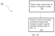
- a method for generating enhanced images of biological samples comprises obtaining, using a microscope, an image of a biological sample; and generating, based on the image, an enhanced image of the biological sample using a machine-learning model.
- the machine-learning model may be trained by: obtaining a plurality of training images comprising a training image of a first type, and a training image of a second type; generating, based on the training image of the first type, a plurality of wavelet coefficients using the machine-learning model; generating, based on the plurality of wavelet coefficients, a synthetic image of the second type; comparing the synthetic image of the second type with the training image of the second type; and updating the machine-learning model based on the comparison.
- a system for training a machine-learning model to generate images of biological samples comprises: a computing system comprising one or more processors, and one or more memories storing a machine-learning model, wherein the computing system is configured to receive a plurality of training images of a first type and one a training image of a second type.
- the computing system may be configured to: generate, based on the training images of the first type, a plurality of wavelet coefficients using the machine-learning model; generate, based on the plurality of wavelet coefficients, a synthetic image of the second type; compare the synthetic image of the second type with the training image of the second type; and update the machine-learning model based on the comparison.
- a system for generating enhanced images of biological samples comprises: a computing system comprising one or more processors, and one or more memories storing a machine-learning model.
- the computing system may be configured to receive an image of a biological sample obtained from a microscope and generate, based on the image, an enhanced image of the biological sample using a machine-learning model.
- the machine-learning model may be been trained by: obtaining a plurality of training images comprising a training image of a first type, and a training image of a second type; generating, based on the training image of the first type, a plurality of wavelet coefficients using the machine-learning model; generating, based on the plurality of wavelet coefficients, a synthetic image of the second type; comparing the synthetic image of the second type with the training image of the second type; and updating the machine-learning model based on the comparison.
- the training image of the first type is a bright-field image of a biological sample.
- the training image of the second type is a fluorescence image of the biological sample.
- the machine-learning model comprises a generator and a discriminator.
- the machine-learning model comprises a conditional GAN model.
- the generator comprises a plurality of neural networks corresponding to a plurality of frequency groups.
- each neural network of the plurality of neural networks is configured to generate wavelet coefficients for a respective frequency group.
- the plurality of neural networks comprises a plurality of U-Net neural networks.
- the discriminator is a PatchGAN neural network.
- the method further comprises: generating, based on the training image of the first type, an image of a third type.
- the image of the third type is a phase shift image.
- the method further comprises: generating, based on the training image of the first type, an image of a fourth type.
- the image of the fourth type comprises segmentation data.
- the training image of the first type is captured using a microscope according to a first illumination scheme.
- the first illumination scheme comprises one or more illumination patterns.
- the training image of the first type is part of a bright-field image array.
- the plurality of training images is a first plurality of training images
- the method further comprising: based on the comparison, identifying a second illumination scheme; obtaining a second plurality of training images comprising one or more images of the first type, wherein the one or more images of the first type are obtained based on the second illumination scheme; training the machine-learning model based on the second plurality of training images.
- the method further comprises obtaining, using a microscope, a plurality of images of the first type; and generating, based on the obtained plurality of images, a plurality of synthetic images of the second type using the machine-learning model.
- the method further comprises training a classifier based on the plurality of synthetic images of the second type.
- the microscope is a first microscope
- the classifier is a first classifier, further comprising: obtaining, using a second microscope, a plurality of images of the second type; training a second classifier based on the plurality of images of the second type; comparing performance of the first classifier and the second classifier.
- the second microscope is a fluorescence microscope.
- An exemplary method for generating enhanced images of biological samples comprises: obtaining, using a microscope, an image of a biological sample; and generating, based on the image, an enhanced image of the biological sample using a machine-learning model, wherein the machine-learning model has been trained by: obtaining a plurality of training images comprising a training image of a first type, and a training image of a second type; generating, based on the training image of the first type, a plurality of wavelet coefficients using the machine-learning model; generating, based on the plurality of wavelet coefficients, a synthetic image of the second type; comparing the synthetic image of the second type with the training image of the second type; and updating the machine-learning model based on the comparison.
- the training image of the first type is a bright-field image of a biological sample.
- the training image of the second type is a fluorescence image of the biological sample.
- the machine-learning model comprises a generator and a discriminator.
- the machine-learning model comprises a conditional GAN model.
- the generator comprises a plurality of neural networks corresponding to a plurality of frequency groups.
- each neural network of the plurality of neural networks is configured to generate wavelet coefficients for a respective frequency group.
- the plurality of neural networks comprises a plurality of U-Net neural networks.
- the discriminator is a PatchGAN neural network.
- the method further comprises: generating, based on the training image of the first type, an image of a third type.
- the image of the third type is a phase shift image.
- the method further comprises: generating, based on the training image of the first type, an image of a fourth type.
- the plurality of training images is a first plurality of training images
- the method further comprising: based on the comparison, identifying a second illumination scheme; obtaining a second plurality of training images comprising one or more images of the first type, wherein the one or more images of the first type are obtained based on the second illumination scheme; training the machine-learning model based on the second plurality of training images.
- the method further comprises obtaining, using a microscope, a plurality of images of the first type; and generating, based on the obtained plurality of images, a plurality of synthetic images of the second type using the machine-learning model.
- the method further comprises: training a classifier based on the plurality of synthetic images of the second type.
- the microscope is a first microscope
- the classifier is a first classifier, further comprising: obtaining, using a second microscope, a plurality of images of the second type; training a second classifier based on the plurality of images of the second type; comparing performance of the first classifier and the second classifier.
- the second microscope is a fluorescence microscope.
- An exemplary system for training a machine-learning model to generate images of biological samples comprises: a computing system comprising one or more processors, and one or more memories storing a machine-learning model, wherein the computing system is configured to receive a plurality of training images of a first type and one a training image of a second type, and wherein the computing system is configured to generate, based on the training images of the first type, a plurality of wavelet coefficients using the machine-learning model; generate, based on the plurality of wavelet coefficients, a synthetic image of the second type; compare the synthetic image of the second type with the training image of the second type; and update the machine-learning model based on the comparison.
- the training image of the first type is a bright-field image of a biological sample.
- the training image of the second type is a fluorescence image of the biological sample.
- the machine-learning model comprises a generator and a discriminator.
- the machine-learning model comprises a conditional GAN model.
- the generator comprises a plurality of neural networks corresponding to a plurality of frequency groups.
- each neural network of the plurality of neural networks is configured to generate wavelet coefficients for a respective frequency group.
- the plurality of neural networks comprises a plurality of U-Net neural networks.
- the discriminator is a PatchGAN neural network.
- the computing system is further configured to: generate, based on the training image of the first type, an image of a third type.
- the image of the third type is a phase shift image.
- the computing system is further configured to: generate, based on the training image of the first type, an image of a fourth type.
- the image of the fourth type comprises segmentation data.
- the microscope is a first microscope
- the classifier is a first classifier
- the computing system is further configured to: obtain, using a second microscope, a plurality of images of the second type; train a second classifier based on the plurality of images of the second type; compare performance of the first classifier and the second classifier.
- the training image of the second type is a fluorescence image of the biological sample.
- the machine-learning model comprises a generator and a discriminator.
- each neural network of the plurality of neural networks is configured to generate wavelet coefficients for a respective frequency group.
- the plurality of neural networks comprises a plurality of U-Net neural networks.
- the discriminator is a PatchGAN neural network.
- the machine learning model is further trained by generating, based on the training image of the first type, an image of a third type.
- the machine-learning model has been trained by: generating, based on the training image of the first type, an image of a fourth type.
- the image of the fourth type comprises segmentation data.
- the training image of the first type is captured using a microscope according to a first illumination scheme.
- the first illumination scheme comprises one or more illumination patterns.
- the training image of the first type is part of a bright-field image array.
- the plurality of training images is a first plurality of training images
- the machine-learning model has been trained by: based on the comparison, identifying a second illumination scheme; obtaining a second plurality of training images comprising one or more images of the first type, wherein the one or more images of the first type are obtained based on the second illumination scheme; training the machine-learning model based on the second plurality of training images.
- the machine-learning model has been trained by: obtaining, using a microscope, a plurality of images of the first type; and generating, based on the obtained plurality of images, a plurality of synthetic images of the second type using the machine-learning model.
- the machine-learning model has been trained by: training a classifier based on the plurality of synthetic images of the second type.
- the microscope is a first microscope, wherein the classifier is a first classifier, wherein the machine-learning model has been trained by: obtaining, using a second microscope, a plurality of images of the second type; training a second classifier based on the plurality of images of the second type; comparing performance of the first classifier and the second classifier.
- An exemplary method of processing images of a biological sample to obtain one or more output images comprises: obtaining a plurality of images of the biological sample using a plurality of configurations of a SLM of an optical system, wherein the SLM is located in an optical path between the biological sample and an image recording device; and inputting the plurality of images of the biological sample into a trained machine-learning model to obtain the one or more outputs images.
- At least one configuration of the plurality of configurations of the SLM is to generate one or more optical aberrations.
- generating one or more optical aberrations comprises a spherical aberration, astigmatism, defocus, distortion, tilt, or any combination thereof.
- At least one configuration of the plurality of configurations of the SLM is to enhance one or more features.
- the one or more features comprise a cell border, an actin filament, nuclear shape, cytoplasm segmentation, or any combination thereof.
- At least one configuration of the plurality of configurations of the SLM is to reduce optical aberrations.
- the plurality of SLM configurations is to obtain images of the biological sample at different depths.
- the machine-learning model is configured to generate, based on an image of a first type, an image of a second type.
- the first type of images are bright-field images.
- the second type of images are fluorescence images.
- the second type of images are enhanced versions of the first type of images.
- the machine-learning model is a GAN model or a self-supervised model.
- the plurality of images are obtained using a plurality of configurations of a light source of the optical system.
- the light source is a LED array of the optical system.
- At least one configuration of the plurality of SLM configurations is obtained by: training the machine-learning model; evaluating the trained machine-learning model; and identifying the at least one configuration based on the evaluation.
- the trained machine-learning model is configured to receive an input image and output an enhanced version of the input image.
- the enhanced version of the input image comprises one or more enhanced cellular phenotypes.
- An exemplary electronic device for processing images of a biological sample to obtain one or more output images comprises: one or more processors; a memory; and one or more programs, wherein the one or more programs are stored in the memory and configured to be executed by the one or more processors, the one or more programs including instructions for: obtaining a plurality of images of the biological sample using a plurality of configurations of a SLM of an optical system, wherein the SLM is located in an optical path between the biological sample and an image recording device; and inputting the plurality of images of the biological sample into a trained machine-learning model to obtain the one or more output images.
- An exemplary non-transitory computer-readable storage medium stores one or more programs for processing images of a biological sample to obtain one or more output images, the one or more programs comprising instructions, which when executed by one or more processors of an electronic device, cause the electronic device to: obtain a plurality of images of the biological sample using a plurality of configurations of a SLM of an optical system, wherein the SLM is located in an optical path between the biological sample and an image recording device; and input the plurality of images of the biological sample into a trained machine-learning model to obtain the one or more output images.
- An exemplary method of classifying images of a biological sample comprises: obtaining a plurality of images of the biological sample using a plurality of configurations of an SLM of an optical system, wherein the SLM is located in an optical path between the biological sample and an image recording device; and inputting the plurality of images of the biological sample into a trained machine-learning model to obtain one or more classification outputs.
- At least one configuration of the plurality of configurations of the SLM is to generate one or more optical aberrations.
- generating one or more optical aberrations comprises a spherical aberration, astigmatism, defocus, distortion, tilt, or any combination thereof.
- At least one configuration of the plurality of configurations of the SLM is to enhance one or more features.
- the one or more features comprise a cell border, an actin filament, nuclear shape, cytoplasm segmentation, or any combination thereof.
- At least one configuration of the plurality of configurations of the SLM is to reduce optical aberrations.
- the plurality of SLM configurations is to obtain images of the biological sample at different depths.
- the plurality of images are obtained using a plurality of configurations of a light source of the optical system.
- the light source is a LED array of the optical system.
- At least one configuration of the plurality of SLM configurations is obtained by: training the machine-learning model; evaluating the trained machine-learning model; and identifying the at least one configuration based on the evaluation.
- the trained machine-learning model is configured to receive an input image and detect one or more pre-defined objects in the input image.
- the pre-defined objects include a diseased tissue.
- An exemplary electronic device for classifying images of a biological sample comprises: one or more processors; a memory; and one or more programs, wherein the one or more programs are stored in the memory and configured to be executed by the one or more processors, the one or more programs including instructions for: obtaining a plurality of images of the biological sample using a plurality of configurations of an SLM of an optical system, wherein the SLM is located in an optical path between the biological sample and an image recording device; and inputting the plurality of images of the biological sample into a trained machine-learning model to obtain one or more classification outputs.
- An exemplary non-transitory computer-readable storage medium stores one or more programs for classifying images of a biological sample, the one or more programs comprising instructions, which when executed by one or more processors of an electronic device, cause the electronic device to: obtain a plurality of images of the biological sample using a plurality of configurations of an SLM of an optical system, wherein the SLM is located in an optical path between the biological sample and an image recording device; and input the plurality of images of the biological sample into a trained machine-learning model to obtain one or more classification outputs.
- An exemplary method for training a machine-learning model comprises: obtaining a plurality of images of a biological sample using a plurality of configurations of an SLM of an optical system, wherein the SLM is located in an optical path between the biological sample and an image recording device; and training the machine-learning model using the plurality of images.
- At least one configuration of the plurality of configurations of the SLM is to generate one or more optical aberrations.
- generating one or more optical aberrations comprises a spherical aberration, astigmatism, defocus, distortion, tilt, or any combination thereof.
- At least one configuration of the plurality of configurations of the SLM is to enhance one or more features.
- the one or more features comprise a cell border, an actin filament, nuclear shape, cytoplasm segmentation, or any combination thereof.
- At least one configuration of the plurality of configurations of the SLM is to reduce optical aberrations.
- At least one configuration of the plurality of configurations of the SLM is to obtain images of the biological sample at different depths.
- the machine-learning model is configured to generate, based on an image of a first type, an image of a second type.
- the first type of images are bright-field images.
- the second type of images are fluorescence images.
- the machine-learning model is a GAN model or a self-supervised model.
- the machine-learning model is a classification model.
- the plurality of images are obtained using a plurality of configurations of a light source of the optical system.
- the light source is a LED array of the optical system.
- training the machine-learning model comprises: (a) training the machine-learning model using a first image, wherein the first image is obtained using a first configuration of the SLM of the optical system; (b) evaluating the trained machine-learning model; (c) based on the evaluation, identifying a second configuration of the SLM; and (d) training the machine-learning model using a second image, wherein the second image is obtained using the second configuration of the SLM of the optical system.
- the evaluation is based on a loss function of the machine-learning model.
- the trained machine-learning model is configured to receive an input image and output an enhanced version of the input image.
- the pre-defined objects include a diseased tissue.
- An exemplary electronic device for training a machine-learning model comprises: one or more processors; a memory; and one or more programs, wherein the one or more programs are stored in the memory and configured to be executed by the one or more processors, the one or more programs including instructions for: obtaining a plurality of images of a biological sample using a plurality of configurations of an SLM of an optical system, wherein the SLM is located in an optical path between the biological sample and an image recording device; and training the machine-learning model using the plurality of images.
- An exemplary non-transitory computer-readable storage medium stores one or more programs for training a machine-learning model, the one or more programs comprising instructions, which when executed by one or more processors of an electronic device, cause the electronic device to: obtain a plurality of images of a biological sample using a plurality of configurations of an SLM of an optical system, wherein the SLM is located in an optical path between the biological sample and an image recording device; and train the machine-learning model using the plurality of images.
- An exemplary method of generating enhanced images of biological samples comprises: obtaining, using a microscope, an image of a biological sample illuminated using an illumination pattern of an illumination source, wherein the illumination pattern is determined by: training a classification model configured to receive an input image and output a classification result, training, using the trained classification model, a machine-learning model having an plurality of weights corresponding to a plurality of illumination settings, and identifying the illumination pattern based on the plurality of weights of the trained machine-learning model; and generating an enhanced image of the biological sample by inputting the obtained image of the biological sample into the trained machine-learning model.
- the obtained image is a bright-field image.
- the enhanced image is a fluorescence image, a phase image, or a combination thereof.
- the illumination source comprises an array of illumination emitters.
- the illumination source is a LED array.
- the illumination pattern indicates whether each illumination emitter is turned on or off and the intensity of each illumination emitter.
- each illumination setting of the plurality of illumination settings corresponds to a respective illumination emitter of the illumination source; and wherein each weight corresponds to an intensity of the respective illumination emitter.
- the classification model is configured to receive an input phase image or an input fluorescence image and output a classification result indicative of one class out of a plurality of pre-defined classes.
- the plurality of pre-defined classes comprises a healthy class and a diseased class.
- the machine-learning model is a GAN model comprising an attention layer comprising the plurality of weights, a discriminator, and a generator.
- the machine-learning model is a conditional GAN model.
- the generator comprises a plurality of neural networks corresponding to a plurality of frequency groups.
- each neural network of the plurality of neural networks is configured to generate wavelet coefficients for a respective frequency group.
- the plurality of neural networks comprises a plurality of U-Net neural networks.
- the discriminator is a PatchGAN neural network.
- training, using the trained classification model, the machine-learning model comprises: applying the plurality of weights to a plurality of bright-field training images; aggregating the plurality of weighted bright-field training images into an aggregated bright-field image; inputting the aggregated bright-field training image into the machine-learning model to obtain an enhanced training image and a generator loss; inputting the enhanced training image into the trained classifier to obtain a classifier loss; augmenting the generator loss based on the classifier loss; and updating the plurality of weights based on the augmented generator loss.
- the method further comprises: classifying the enhanced image using the trained classifier.
- the method further comprises: displaying the enhanced image.
- An exemplary system for generating enhanced images of biological samples comprises: one or more processors; a memory; and one or more programs, wherein the one or more programs are stored in the memory and configured to be executed by the one or more processors, the one or more programs including instructions for: obtaining, using a microscope, an image of a biological sample illuminated using an illumination pattern of an illumination source, wherein the illumination pattern is determined by: training a classification model configured to receive an input image and output a classification result, training, using the trained classification model, a machine-learning model having an plurality of weights corresponding to a plurality of illumination settings, and identifying the illumination pattern based on the plurality of weights of the trained machine-learning model; and generating an enhanced image of the biological sample by inputting the obtained image of the biological sample into the trained machine-learning model.
- An exemplary non-transitory computer-readable storage medium stores one or more programs for generating enhanced images of biological samples, the one or more programs comprising instructions, which when executed by one or more processors of an electronic device, cause the electronic device to: obtain, using a microscope, an image of a biological sample illuminated using an illumination pattern of an illumination source, wherein the illumination pattern is determined by: training a classification model configured to receive an input image and output a classification result, training, using the trained classification model, a machine-learning model having an plurality of weights corresponding to a plurality of illumination settings, and identifying the illumination pattern based on the plurality of weights of the trained machine-learning model; and generate an enhanced image of the biological sample by inputting the obtained image of the biological sample into the trained machine-learning model.
- An exemplary method of evaluating a treatment with respect to a disease of interest comprises: receiving a first plurality of images depicting a first set of healthy biological samples not affected by the disease of interest; receiving a second plurality of images depicting a second set of untreated biological samples affected by the disease of interest; receiving a third plurality of images depicting a third set of treated biological samples affected by the disease of interest and treated by the treatment; inputting the first plurality of images into a trained machine-learning model to obtain a first plurality of enhanced images; inputting the second plurality of images into the trained machine-learning model to obtain a second plurality of enhanced images; inputting the third plurality of images into the trained machine-learning model to obtain a third plurality of enhanced images; comparing the first plurality of enhanced images, the second plurality of enhanced images, and the third plurality of enhanced images to evaluate the treatment.
- the first plurality of images, the second plurality of images, and the third plurality of images are bright-field images.
- the first plurality of enhanced images, the second plurality of enhanced images, and the third plurality of enhanced images are fluorescence images.
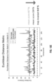
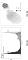
- comparing the first plurality of enhanced images, the second plurality of enhanced images, and the third plurality of enhanced images to evaluate the treatment further comprises: determining a first distribution based on signals of the biomarker in the first plurality of enhanced images; determining a second distribution based on signals of the biomarker in the second plurality of enhanced images; and determining a third distribution based on signals of the biomarker in the third plurality of enhanced images.
- comparing the first plurality of enhanced images, the second plurality of enhanced images, and the third plurality of enhanced images to evaluate the treatment further comprises: comparing the first distribution, the second distribution, and the third distribution to evaluate the treatment.
- the discriminator is a PatchGAN neural network.
- An exemplary system for evaluating a treatment with respect to a disease of interest comprises: one or more processors; a memory; and one or more programs, wherein the one or more programs are stored in the memory and configured to be executed by the one or more processors, the one or more programs including instructions for: receiving a first plurality of images depicting a first set of healthy biological samples not affected by the disease of interest; receiving a second plurality of images depicting a second set of untreated biological samples affected by the disease of interest; receiving a third plurality of images depicting a third set of treated biological samples affected by the disease of interest and treated by the treatment; inputting the first plurality of images into a trained machine-learning model to obtain a first plurality of enhanced images; inputting the second plurality of images into the trained machine-learning model to obtain a second plurality of enhanced images; inputting the third plurality of images into the trained machine-learning model to obtain a third plurality of enhanced images; comparing the first plurality of enhanced images, the second plurality of enhanced images, and the third plurality
- An exemplary non-transitory computer-readable storage medium stores one or more programs for evaluating a treatment with respect to a disease of interest, the one or more programs comprising instructions, which when executed by one or more processors of an electronic device, cause the electronic device to: receiving a first plurality of images depicting a first set of healthy biological samples not affected by the disease of interest; receiving a second plurality of images depicting a second set of untreated biological samples affected by the disease of interest; receiving a third plurality of images depicting a third set of treated biological samples affected by the disease of interest and treated by the treatment; inputting the first plurality of images into a trained machine-learning model to obtain a first plurality of enhanced images; inputting the second plurality of images into the trained machine-learning model to obtain a second plurality of enhanced images; inputting the third plurality of images into the trained machine-learning model to obtain a third plurality of enhanced images; comparing the first plurality of enhanced images, the second plurality of enhanced images, and the third plurality of enhanced images to evaluate the treatment.
- the present disclosure includes methods, systems, electronic devices, non-transitory storage media, and apparatuses for performing ML-based generation of image data at scale.
- the generated image data e.g., image data of biological samples
- can provide sufficient richness and depth for downstream processing e.g., phenotyping
- embodiments of the present disclosure comprises a set of computational and hardware optimization methods that extends the current dimensionality of classic microscopy techniques.
- Embodiments of the present disclosure can process multiple bright-field images of biological samples and produce enhanced images of the biological samples.
- the enhanced images include but are not limited to: fluorescence images, phase shift images, semantic map, polarization map, refractive map (2D and 3D), absorbance map, and other image modalities.
- Bright-field images of biological samples can be obtained at scale and at low cost due to inexpensive equipment (e.g., relative to fluorescence microscopes), ease of clinical deployment, and low processing and storage resource requirements.
- Obtaining bright-field images is generally non-invasive and involves low photo-toxicity. Thus, bright-field images can be obtained efficiently and at scale.
- the enhanced images provide sufficient richness and depth for downstream processing (e.g., phenotypic exploration).
- Embodiments of the present disclosure include a machine-learning model that is trained to receive a first type of image and translate the input image into other imaging modalities.
- An exemplary machine-learning model can receive the first type of image and translate the input image into a second type of image (e.g., an enhanced image).
- different image types refer to different imaging modalities.
- the first type of images are bright-field images.
- the bright-field images can be captured from illuminating in vitro (or biopsy) cell samples with an inexpensive LED array.
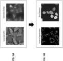
- the second type of images include fluorescence images.
- the generated fluorescence images exhibit high contrast features that are not directly visible in bright-field images and can be used for downstream processing (e.g., phenotyping).
- Embodiments of the present disclosure reduce or eliminate the need to capture real fluorescence images (or other special image modalities) of biological samples for downstream analysis, and allow bright-field images to be widely used for a variety of purposes. This is particularly beneficial to live cell imaging.
- the disclosed methods could be used for the monitoring and optimization of cell differentiation experimental protocols.
- time consuming activities linked to cells staining and fixation could be avoided.
- the dosing time which is the incubation time of a drug with the cells under observation could also be optimized by the software.
- researchers would no longer to need to arbitrarily decide the best incubation time, as the software would be able to notify the researcher of the optimized incubation time.
- the machine-learning techniques used to translate the bright-field images into other modalities require lower processing and storage resource utilization.
- embodiments of the present disclosure present technical improvements in the field of medical imaging while enhancing the operability and functioning of computing systems.
- Embodiments of the present disclosure further include a machine-learning model that is trained to receive the first type of image and translate the input image into a third type of image.
- the third type of image include image data indicative of various optical properties (e.g., phase shift) of the biological sample captured.
- Embodiments of the present disclosure further include a machine-learning model that is trained to receive the first type of image and translate the input image into a fourth type of image.
- the fourth type of image includes image data indicative of segmentation data (e.g., cell boundaries).
- embodiments of the present disclosure can further translate input images into numerous other types of image capturing a variety of imaging characteristics, such as a semantic map, a polarization map, a refractive map (2D or 3D), absorbance map, etc.
- a single machine-learning model is trained to perform multiple translation tasks simultaneously.
- the same machine-learning model can receive the first type of image and generate multiple types of images (e.g., second type, third type, fourth type of image).
- the machine-learning model can be a Generative Adversarial Network ("GAN”) model.
- GAN Generative Adversarial Network
- the GAN network can be a conditional GAN (“cGAN”) model.
- the machine-learning model converts an input image into its corresponding wavelet coefficients and generates one or more output images in wavelet coefficients.
- the compact and multi-scale representation of images coupled with the intrinsic non-linear options of a neural network achieves multiple goals at once.
- the wavelet-based representation solves the inherent class imbalance problem that most of the generative models face. Specifically, most input image data comprise abundant low frequency signals but fewer high frequency signals.
- the wavelet-based representation extracts and maintains the overall geometry of the input image data.
- the discriminator of the model ensures that the real and generated images (e.g., real v. generated fluorescence images) are indistinguishable.
- Embodiments of the present disclosure further includes hardware optimization methods.
- embodiments of the present disclosure can further optimize the illumination schema of a microscope (e.g., the microscope that obtains the first type of images) dynamically.
- the microscope that is used to capture the first type of images can be tuned or programmed to provide different illumination schemes during the training process.
- an optimal illumination scheme for capturing the first type of images can be identified.
- the optimal illumination scheme can be used to capture the first type of images (e.g., bright-field images) so as to extract the best representation of the biological sample for wavelet-based image transformation (e.g., for downstream phenotypic exploration).
- Embodiments of the present disclosure further includes evaluating the robustness of the generated images of the machine-learning model.
- a first downstream classifier is trained using real images (e.g., real fluorescence images), and a second downstream classifier is trained using generated images (e.g., generated fluorescence images). The performance of the two classifiers can be compared to evaluate the robustness of the generated images as training data in downstream tasks.
- embodiments of the present disclosure comprise an integrated platform that simultaneously solves many problems: image enhancement, phase retrieval, low photo-toxicity, realistic virtual painting of bright-field images, and robustness in downstream tasks.
- Embodiments of the present disclosure can evaluate the robustness of the generated images via downstream classification tasks. These tasks are integrated to the platform and close the loop of data generation from non-invasive bright-field images to fluorescent images.
- the system may optimize parameters of the bright-field microscope acquisition system during use. Illumination patterns of the LED array, and other parameters of the bright-field microscope acquisition system, including, for example, the focus position of the microscope objective and activation timings of a spatial light modulator (SLM) may be optimized by back-propagation during downstream classification tasks.
- SLM spatial light modulator
- the platform performs a cascade of perturbations to the cells and learn to optimize the illumination scheme to extract the best representation of the cells for phenotypic exploration.
- an illumination pattern can indicate whether each illumination emitter of an illumination source (e.g., each LED on a LED array) is to be turned on or off and the intensity of each illumination emitter.
- the system can determine an optimal illumination pattern by training a machine-learning model having an attention layer comprising an plurality of weights corresponding to the intensities of a plurality of illumination emitters (e.g., a plurality of weights corresponding to the intensities of a plurality of LEDs on the LED array).
- the plurality of weights are applied to a plurality of training images (e.g., bright-field images) illuminated by different illumination emitters.
- the aggregated image can be inputted into the machine-learning model to determine a loss and the model, including the weights in the attention layer, can be updated based on the loss accordingly.
- an illumination pattern can be determined based on the weights in the attention layer of the trained machine-learning model, as each weight can correspond to the desired intensity level of the corresponding illumination emitter. Accordingly, the process involves only capturing images using a limited number of illumination settings (e.g., turning on a single illumination emitter at a time to capture images) and does not require physically adjusting the intensities of the illumination emitters in order to identify an optimal illumination pattern.
- training the machine-learning model comprises first training a classifier corresponding to the downstream task (e.g., classifying healthy v. diseased tissues based on an image) and then using the outputs of the classifier to guide the training of the machine-learning model.
- a classifier corresponding to the downstream task e.g., classifying healthy v. diseased tissues based on an image
- Some embodiments of the present disclosure can evaluate candidate treatments with respect to a disease of interest.
- the system receives a first plurality of images depicting a first set of healthy biological samples not affected by the disease of interest; receives a second plurality of images depicting a second set of untreated biological samples affected by the disease of interest; and receives a third plurality of images depicting a third set of treated biological samples affected by the disease of interest and treated by the candidate treatment.
- the images are inputted into a machine-learning model to obtain enhanced images, and the enhanced images are compared to evaluate the treatment (e.g., by analyzing the distributions of the images).
- an exemplary optical system comprises a programmable spatial light modulator ("SLM").
- SLM of the optical system can improve the performance of a machine-learning model via the training stage (e.g., by providing a rich training dataset) and/or via the inference stage (e.g., by providing input data under a variety of optical settings or an optimal setting).
- the SLM is programmed without requiring any mechanical movement or mechanical modifications to the optical system.
- the SLM provides additional degrees of freedom and sources of contrast to control the microscope in a programmable way.
- the SLM can be programmed to generate optical aberrations that enhance critical phenotypes.
- the SLM can be programmed to provide different modulations, thus producing a variety of images that allow the exploration of deep samples at a high speed.
- the SLM also allows identification of an optimal imaging setup to infer cellular phenotypes and reconstruct alternative images modalities in a supervised fashion. Multi-focus acquisitions are possible without any mechanical movements, thus accelerating and improving the downstream tasks. Three-dimensional phase tomography and reconstruction are therefore accelerated and improved.
- first means "first," “second,” etc. to describe various elements, these elements should not be limited by the terms. These terms are only used to distinguish one element from another.
- a first graphical representation could be termed a second graphical representation, and, similarly, a second graphical representation could be termed a first graphical representation, without departing from the scope of the various described embodiments.
- the first graphical representation and the second graphical representation are both graphical representations, but they are not the same graphical representation.
- FIG. 1 illustrates an exemplary process for training a machine-learning model configured to generate enhanced images of biological samples, in accordance with some embodiments.
- training data 120 comprises a first type of images 122 and a second type of images 124.
- the images are images of biological samples, and the biological samples can include one or more collections of stained, unstained, perturbed and/or unperturbed biological samples.
- the first type of image data 122 comprises a set of bright-field images
- the second type of image data 124 comprises images in a different modality (e.g., fluorescence images).
- the first type of images 122 can be obtained using a bright-field microscope
- the second type of images 124 can be obtained using a fluorescence microscope.
- an illumination pattern is indicative of the settings with which an object is illuminated.
- an illumination pattern can be defined by one or more parameters indicating the spatial relationship (e.g., distance, angle) between the object and the illumination source, one or more parameters indicating the setup of the illumination source, or a combination thereof.
- an illumination pattern can indicate a set of activated LED light sources, a specific out-of-focus / polarization setup, etc.
- the microscope that captures the first type of images can be a microscope that supports multiple illumination patterns.
- the microscope can provide a programmable illumination source (e.g., LED array, laser), an adaptive optics system (SLM, micro-mirrors), or a combination thereof.
- a programmable illumination source e.g., LED array, laser
- SLM adaptive optics system
- micro-mirrors micro-mirrors
- the training data 120 can be organized as three-dimensional image data (e.g., an image array).
- the training data 120 can be of dimensions (B, C, H, W) in which B indicates the batch size, C indicates the number of channels (i.e., illumination patterns), H indicates the height, and W indicates the width.
- B indicates the batch size
- C indicates the number of channels (i.e., illumination patterns)
- H indicates the height
- W indicates the width.
- C equals 1 if there is only a single bright-field image
- C is larger than 1 if there is a stack of bright-field images.
- one or more images in the training data 120 can be normalized before they are used to train the machine-learning model 100.
- fluorescence images can be normalized based on illumination or intensity parameters.
- the training data 120 is used to train the machine-learning model 100.
- the model 100 is a Generative Adversarial Network ("GAN") model.
- the GAN network can be a conditional GAN (“cGAN”) model.
- the GAN network comprises a generator and a discriminator.
- the generator is trained to receive the first type of images (e.g., bright-field images) and translate the input images into the second type of images (e.g., fluorescence images).
- the training step includes comparing real images of the first type 122 with real images of the second type 124 to determine a ground truth baseline for what a wavelet-based transformation of the first type of image 122 should seek to accomplish.
- the generator output (i.e., the generated fluorescence images) can be connected directly to the discriminator input.
- the discriminator is trained to distinguish the generated images of the second type (e.g., generated fluorescence images) from real images of the second type (e.g., real fluorescence images).
- the discriminator's output can be used by the generator to update the generator's weights such that the generator learns to generate images that the discriminator will classify as real images.
- the illumination parameters can be updated during the training of the model 100.
- the illumination scheme can be continually updated and training data can be obtained according to the updated illumination scheme to further train the model 100, as described in detail below.
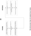
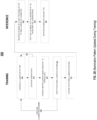
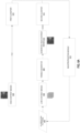
- FIGS. 2A and 2B illustrate exemplary processes 200 and 250 for training and applying the machine learning model (e.g., model 100), in accordance with some embodiments.
- FIG. 2A illustrates the process when the parameters of the microscope cannot be changed during acquisition of the training data.
- FIG. 2B illustrates the process when the parameters of the microscope can be changed during acquisition of the training data and thus an optimal illumination pattern can be identified.
- Each of the processes can be performed at least in part using one or more electronic devices.
- the blocks of each process step depicted in FIGS. 2A and 2B can be divided up between multiple electronic devices.
- some blocks are, optionally, combined, the order of some blocks is, optionally, changed, and some blocks are, optionally, omitted.
- additional steps may be performed in combination with the process. Accordingly, the operations as illustrated (and described in greater detail below) are exemplary by nature and, as such, should not be viewed as limiting.
- the parameters of the microscope cannot be changed during the acquisition of the bright-field images.
- all of the bright-field images in the training data e.g., training data 120 are obtained based on the same illumination pattern.
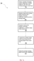
- training data (e.g., training data 120 in FIG. 1 ) is obtained at least partially according to the default illumination pattern.
- the training data comprises a first type of images (e.g., bright-field images), which are obtained according to the default illumination pattern by a bright-field microscope, and a second type of images (e.g., fluorescence images) obtained by a fluorescence microscope.
- a machine-learning model (e.g., model 100 in FIG. 1 ) is trained based on the training data.
- the model can be a GAN model.
- the GAN network can be a conditional GAN (“cGAN”) model.
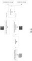
- FIGS. 3A , 3C , and 3D illustrates the training process of the machine-learning model, in accordance with some embodiments.
- the GAN model comprises the generator 302 and a discriminator 304.
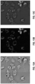
- the generator 302 is trained to receive a first type of images 310 (e.g., bright-field images) and generate a second type of images 312 (e.g., fluorescence images).
- the first type of images 310 comprises the bright-field image array described above.
- the generator output i.e., the generated fluorescence images
- the discriminator 304 is trained to distinguish the generated images of the second type 312 (e.g., generated fluorescence images) from real images of the second type 314 (e.g., real fluorescence images).
- the real images of the second type 314 comprises the fluorescence image array described above.
- the discriminator's output can be used by the generator to update the generator's weights such that the generator learns to generate images that the discriminator will classify as real images, as described in detail below.
- the generator 302 and the discriminator 304 are neural networks.
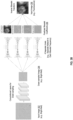
- FIG. 3B illustrates operations of an exemplary generator, in accordance with some embodiments.
- the input image 352 can be a single image from a bright-field image array or an entire bright-field image array.
- the input image 352 can be of dimensions (B, C, H, W) in which B indicates the batch size, C indicates the number of channels, H indicates the height, and W indicates the width.
- B indicates the batch size
- C indicates the number of channels
- H indicates the height
- W indicates the width.
- C equals 1 if there is only a single bright-field image
- C is larger than 1 if there is a stack of bright-field images.
- the generator comprises a series of convolutional layers for down-sampling the input image 352 to obtain a down-sampled input image 354.
- the input image 353 can be down-sampled to half of its original size. For example, if the input is 256 * 256 in the spatial size, it will be reduced to 128 * 128.
- the down-sampled image 354 is then passed to a plurality of neural networks.
- the plurality of neural networks comprises four U-Net neural networks.
- a U-Net network is a convolutional network for image-to-image translation. Details of the design and implementation of a U-Net network can be found, for example, in Ronneberger et al., "U-Net: Convolutional Networks for Biomedical Image Segmentation ,” which is hereby incorporated by reference in its entirety.
- the plurality of neural networks can correspond to different frequency groups in the wavelet domain.
- the four U-Net networks are responsible for low frequency, high frequency (horizontal), high frequency (vertical), and high frequency (diagonal), respectively.
- low frequency signals correspond to very large features with respect to the size of the image (for example when imaging cells, having a size magnitude of the order of the cytoplasm or the nucleus).
- High frequency information are very fine small image features (for example, having a size magnitude of the order of mitochondria, microtubules).
- Low frequency signals correspond to the first scale of wavelet coefficients.
- the high frequency are encoded in higher scale wavelet coefficients.
- the plurality of neural networks operate independently and do not share weights.
- Each neural network is configured to output (or predict) wavelet coefficients for the respective frequency group.
- a loss function is applied to the predicted wavelet coefficients 356 and the true wavelet coefficients of the real fluorescence image. The loss function is described further below with reference to FIGS. 3C and 3D .
- the generated fluorescence image 358 in the image domain can be obtained by applying inverse wavelet transform on predicted coefficients 356.
- FIG. 3C illustrates the back-propagation process of the discriminator 304, according to some embodiments.
- the discriminator 304 is a model (e.g., a neural network) trained to provide an output based on a given image.
- the training data of the discriminator 304 comprises real images of the second type 314 (e.g., real fluorescence images) and synthetic images of the second type 312 (e.g., generated fluorescence images) generated by the generator 302.
- the discriminator 304 is a PatchGAN network. Details of the design and implementation of the PatchGAN network can be found, for example, in Isola et al., "Image-to-Image Translation with Conditional Adversarial Networks ,” which is incorporated by reference in its entirety.
- a discriminator loss 322 can be calculated based on the generator's outputs (i.e., the predicted wavelet coefficients).
- f(x) is the discriminator's output based on wavelet coefficients of a real fluorescence image
- w is the model weights of the discriminator
- m is the size of the mini-batch
- f is the discriminator model
- x is the real image
- z is the input (bright-field)
- G is the generator model
- f(G(z)) is the discriminator's output based on the predicted wavelet coefficients corresponding to a synthetic fluorescence image.
- the discriminator 304 is configured to maximize this function. In other words, it tries to maximize the difference between its output based on real images and its output based on synthetic images. As depicted in FIG. 3C , the discriminator updates its weights through back-propagation based on the discriminator loss 332 through the discriminator network.
- FIG. 3D illustrates the back-propagation process of the generator 302, according to some embodiments.
- the generator 302 is a neural network configured to receive a first type of images 310 and generate a second type of images 312, as described with reference to FIGS. 3A and 3B .
- the predicted wavelet coefficients by the generator are inputted into the discriminator 304.
- a generator loss 324 can be calculated.
- the reconstruction loss operating in the wavelet domain, has the property to naturally balance the contribution of low and high frequencies.
- the wavelet coefficients can be split into two categories: low (one block) and high frequency (3 blocks). Three of the four UNet branches can be dedicated to the high frequency blocks. Low frequency information can more easily be recovered; therefore, having more computing power dedicated to the high frequency helps with the reconstruction of fine details in the images.
- the loss function operating in the wavelet domain benefits from this organization of the signal (three times more high frequency information than low frequency information).
- the wavelet coefficients can be split into more than two categories, for example, three categories (high, medium, low frequencies), four categories, or more than four categories.
- the generator 302 is configured to maximize this function. In other words, it tries to maximize the discriminator's output based on its synthetic images.
- the generator loss is back-propagated through both the discriminator 304 and the generator 302 to obtain gradients, which are in turn used to adjust the generator weights.
- the generator 302 and the discriminator 304 are trained in alternating periods. In each period, the discriminator trains for one or more epochs, and the generator trains for one or more epochs. During the discriminator training, the generator may remain constant. Similarly, during the generator training, the discriminator may remain constant.
- the generator can translate the input image into a third type of image (e.g., phase shift image).
- a third type of image e.g., phase shift image
- the generator may also output phase shift images in which each pixel indicates local value of the phase in the image (e.g., -5 to 5 phase information) that can be converted.
- a physics-based image formation model can be used to generate real phase shift images (i.e., the ground-truth phase shift images).
- the image formation model generates images given an absolute knowledge of the microscope (e.g., the aberrations of the optical system) as well as the optical properties of the sample captured (e.g., refractive index, phase). Because the optical properties of the sample can be compared between samples, the risk of batch effects in downstream tasks is almost null.
- a physics based model allows the incorporation of solid a priori knowledge in the generative process.
- S the illumination source
- the microscope PSF or pupil function
- the polarization of S can also be modulated in order to inject more contrast in the collected images.
- S(f) refers to the partially coherent illumination source (LED array).
- X(r) refers to the sample's complex electronic field.
- P(r) refers to the microscope's point spread function (PSF).
- RI(r) refers to the refractive index.
- I refers to the image. The forward model is applied outside of the training loop to obtain the ground truth phase.
- the generator can translate the input image into a fourth type of image.
- the fourth type of image include image data indicative of segmentation data (e.g., cell boundaries).
- the loss function depends on the image modality supported. For semantic segmentation, a L1 norm can be used to infer the discrete labels in the images. For another image modality, another branch can be added to the generator to output the new modality.
- Metadata can be associated with the trained machine-learning model.
- the metadata can include the default illumination pattern (e.g., parameters of the bright-field microscope).
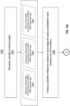
- one or more images of the first type are obtained.
- the images are obtained using the same illumination pattern (e.g., as indicated in the metadata in block 208).
- the one or more images are inputted into the generator (e.g., generator 302) of the trained machine-learning model.
- the generator has been trained to translate the first type of images into the second type of images (e.g., fluorescence images).
- the second type of images e.g., fluorescence images.
- one or more images of the second type are obtained.
- the generated fluorescence images in turn can be used as training data for other machine-learning models, thus eliminating the need to obtain real fluorescence images as training data.
- FIG. 2B illustrate the process when the parameters of the microscope can be changed during acquisition of the training data and thus an optimal illumination pattern can be identified.
- the parameters of the microscope can be programmable such that multiple illumination patterns can be provided by the microscope.
- an illumination pattern is loaded onto a microscope.
- bright-field training images are captured according to the illumination pattern (e.g., bright-field images) and fluorescence training images are also captured by a fluorescence microscope.
- Blocks 252 and 254 can be repeatedly performed, as indicated by the arrow 253.
- a sequence of illumination patterns can be loaded onto the microscope and training data corresponding to the sequence of illumination patterns can be obtained.
- the sequence of illumination patterns is also referred to an illumination scheme herein.
- a machine-learning model is trained based on the training data.
- the model can be a GAN model that operates as described with reference to FIGS. 3A-D .
- the GAN network can be a conditional GAN ("cGAN”) model.
- the model updates the illumination pattern iteratively.
- the illumination pattern is updated by back-propagating the gradient of the loss (e.g., generator loss) to the parameters of the microscope.
- the training procedure of the model minimizes the overall imaging time and minimizes the loss functions associated with translation or classification tasks.
- the system determines which illumination pattern leads to the smallest loss (e.g., generator loss).
- the model produces a first generator loss when translating a first image, produces a second generator loss when translating a second image, etc.
- the losses can be compared and the smallest loss can be identified.
- the illumination pattern that has produced the smallest loss can be identified and a new illumination scheme can be identified accordingly.
- the new illumination scheme can include the best illumination pattern and/or one or more new illumination patterns similar to the best illumination pattern.
- the new illumination scheme can also exclude previously included illumination patterns that have resulted in the biggest loss.
- the identified illumination scheme can be loaded to the microscope to obtain additional training data. This process can be repeated until no more improvement (e.g., on the generator loss) is observed.
- the optimal illumination scheme can be stored at block 261.
- one or more images of the first type are obtained.
- the images are obtained using the optimal illumination scheme stored in block 261.
- the one or more images are inputted into the generator (e.g., generator 302) of the trained machine-learning model.
- the generator has been trained to translate the first type of images into the second type of images (e.g., fluorescence images).
- the generated fluorescence images in turn can be used as training data for other machine-learning models, thus eliminating the need to obtain real fluorescence images as training data.
- FIG. 5 illustrates outputs of an exemplary trained generator using a static microscope setup.
- the trained generator receives input bright-field images and generates phase images and fluorescence images 504.
- FIG. 5 also shows the corresponding real phase images and fluorescence images 506.
- each input image is a composite of four different illuminations.
- the input image is a false color image representing the different illumination patterns.
- FIG. 6A illustrates an exemplary process for determining the robustness of the generated images, in accordance with some embodiments.
- Two classifiers 612 and 614 are trained to receive a fluorescence image and provide an output (e.g., a phenotype classification result).
- Classifier 614 is trained based on real fluorescence images 604 (e.g., real fluorescence images), while classifier 612 is trained based on generated fluorescence images 610.
- the generated fluorescence images are generated by a trained generator 608 (e.g., generator 102, 302) based on bright-field images 506.
- classifier 612 is validated using generated images, while classifier 614 is validated using real images.
- FIG. 6B illustrates an exemplary comparison between two such classifiers.
- the dataset is made of fluorescence images and 3D bright-field images of primary hepatocytes from 12 healthy donors and 12 NASH donors.
- a GAN model is trained to generate fluorescence images from a stack of out of focus bright-field images.
- a comparison is made to determine whether a classifier trained on generated images and validated on real images performs equally well when trained on real images and validated on generated images. As shown in FIG. 6B , there is no drop in the classification accuracy and more importantly, the geometry of the embeddings space of the real images is conserved on the generated images.
- Back-propagation module 616 can be used, for example, to improve the image acquisition parameters used for acquiring bright-field images that are to be enhanced.
- Xi can include a set parameters for the illumination patterns applied to a LED illumination array of a bright-field microscope.
- Xi can also include imaging parameters related to the focus position of the microscope objective and or activation parameters of a spatial light modulator (SLM). All elements of Xi may be variables of the optimization procedure. Therefore in 616 the gradient of the loss function estimated on downstream task [612] (e.g classification, image to image translation, regression) may be back-propagated to optimize the parameters, Xi. For each update to the values of Xi a new set of images may be acquired generating a new data set of images.
- SLM spatial light modulator
- the data used to train the generator 608, the data used to train the first classifier 614 or the second classifier 612, and the data used to evaluate the performance of the classifiers can include overlapping images. Images used in any of the above-described processes can be annotated based on the biological samples captured (e.g., type of cells, whether diseased or healthy) and the perturbations. These annotations can be used for downstream classification tasks (e.g., as training data to train classifiers 612 and 614 in FIG. 6A ) and validation of the predictive models (e.g., to evaluate the performance of the trained classifiers 612 and 614).
- FIG. 7A illustrates an example of a method 700 for training a machine-learning model to generate images of biological samples in accordance with one embodiment.
- the method includes obtaining a plurality of training images comprising a training image of a first type, and a training image of a second type at 702.
- the method further includes generating, based on the training image of the first type, a plurality of wavelet coefficients using the machine-learning model at 704; generating, based on the plurality of wavelet coefficients, a synthetic image of the second type at 706; comparing the synthetic image of the second type with the training image of the second type at 708; and updating the machine-learning model based on the comparison at 710.
- FIG. 7B illustrates an example of a method 750 for generating enhanced images of biological samples in accordance with one embodiment.
- the method includes obtaining, using a microscope, an image of a biological sample at 752.
- the method also includes at 754 generating, based on the image, an enhanced image of the biological sample using the machine-learning model of FIG. 7A .
- FIG. 8 illustrates an example of a computing device in accordance with one embodiment.
- Device 800 can be a host computer connected to a network.
- Device 800 can be a client computer or a server.
- device 800 can be any suitable type of microprocessor-based device, such as a personal computer, workstation, server or handheld computing device (portable electronic device) such as a phone or tablet.
- the device can include, for example, one or more of processor 810, input device 820, output device 830, storage 840, and communication device 860.
- Input device 820 and output device 830 can generally correspond to those described above, and can either be connectable or integrated with the computer.
- Input device 820 can be any suitable device that provides input, such as a touch screen, keyboard or keypad, mouse, or voice-recognition device.
- Output device 830 can be any suitable device that provides output, such as a touch screen, haptics device, or speaker.
- Storage 840 can be any suitable device that provides storage, such as an electrical, magnetic or optical memory including a RAM, cache, hard drive, or removable storage disk.
- Communication device 860 can include any suitable device capable of transmitting and receiving signals over a network, such as a network interface chip or device.
- the components of the computer can be connected in any suitable manner, such as via a physical bus or wirelessly.
- Software 850 which can be stored in storage 840 and executed by processor 810, can include, for example, the programming that embodies the functionality of the present disclosure (e.g., as embodied in the devices as described above).
- Software 850 can also be stored and/or transported within any non-transitory computer-readable storage medium for use by or in connection with an instruction execution system, apparatus, or device, such as those described above, that can fetch instructions associated with the software from the instruction execution system, apparatus, or device and execute the instructions.
- a computer-readable storage medium can be any medium, such as storage 840, that can contain or store programming for use by or in connection with an instruction execution system, apparatus, or device.
- Software 850 can also be propagated within any transport medium for use by or in connection with an instruction execution system, apparatus, or device, such as those described above, that can fetch instructions associated with the software from the instruction execution system, apparatus, or device and execute the instructions.
- a transport medium can be any medium that can communicate, propagate or transport programming for use by or in connection with an instruction execution system, apparatus, or device.
- the transport readable medium can include, but is not limited to, an electronic, magnetic, optical, electromagnetic or infrared wired or wireless propagation medium.
- Device 800 may be connected to a network, which can be any suitable type of interconnected communication system.
- the network can implement any suitable communications protocol and can be secured by any suitable security protocol.
- the network can comprise network links of any suitable arrangement that can implement the transmission and reception of network signals, such as wireless network connections, T1 or T3 lines, cable networks, DSL, or telephone lines.
- an exemplary optical system comprises a programmable SLM.
- An exemplary SLM comprise a high-resolution liquid crystal panel with micron-sized individually addressable pixels, which can be used to shape the wavefront of an optical beam. Grey-level values on the panel are converted into phase shifts. SLM can be used as programmable Fourier filters for generating contrast enhancement or as programmable diffractive optical elements for quantitative phase microscopy, in some embodiments.
- the SLM can be programmed to generate various images during the training stage and/or during the inference stage of machine-learning models to improve the performance of the machine-learning models, as described herein.
- the SLM can be programmed to generate different input images for the trained machine-learning model.
- the SLM can be programmed to generate input images for a trained image transformation model to obtain enhanced versions of the input images.
- the enhanced images can in turn be used for downstream operations.
- the SLM can be programmed to generate input images for a trained classification model to obtain more accurate classification results.
- the SLM can be programmed to generate different images as training data during the training stage of a machine-learning model. Further, SLM can be iteratively programmed, during either the training stage or the inference stage, to identify an optimal setting for capturing images that leads to the best performance of a given machine-learning model.
- FIG. 9 illustrates an exemplary optical system, in accordance with some embodiments.
- An exemplary optical system comprises a light source 902 (e.g., an LED array), objective lens 904, an SLM 906, and a camera 908.
- the optical system has a reflection mode. In the reflection mode, the light source 902 provides illumination to a biological sample 910, which generates reflected light. The reflected light travels through the objective lens 904 and is captured by the camera 908.
- the dash line 912 indicates the intermediate image plane.
- the SLM is placed in the imaging path between the biological sample 910 and the camera 908.
- the SLM is configured to impose spatially varying modulations on the reflected light.
- the SLM allows shaping of an alternative Fourier plane before the reflected light is focused on the camera 908.
- both the light source 902 and the SLM 906 can be programmable, thus allowing additional degrees of freedom to control and optimize the optical system without mechanically moving components of the optical system.
- the configuration of the optical system in FIG. 9 is merely exemplary.
- One of ordinary skill in the art would appreciate that other configurations of the optical system can be used to place the SLM in the imaging path of the optical system to apply optimization techniques described herein.
- FIG. 10 illustrates an exemplary method for analyzing images of a biological sample using a programmable SLM of an optical system, in accordance with some embodiments.
- Process 1000 is performed, for example, using one or more electronic devices implementing a software platform.
- process 1000 is performed using a client-server system, and the blocks of process 1000 are divided up in any manner between the server and one or more client devices.
- process 1000 is performed using only one or more client devices.
- some blocks are, optionally, combined, the order of some blocks is, optionally, changed, and some blocks are, optionally, omitted.
- additional steps may be performed in combination with the process 1000. Accordingly, the operations as illustrated (and described in greater detail below) are exemplary by nature and, as such, should not be viewed as limiting.
- an exemplary system obtains a plurality of images of the biological sample (e.g., sample 910 in FIG. 9 ).
- the plurality of images are generated using a plurality of configurations of an SLM of an optical system (e.g., SLM 906 in FIG. 9 ).
- the SLM is located in an optical path between the biological sample and an image recording device (e.g., camera 908).
- At least one configuration of the SLM is to generate one or more optical aberrations in the resulting image(s).
- the optical aberrations can include spherical aberration, astigmatism, defocus, tilt, or any combination thereof.
- more information can be captured in and/or derived from images with optical aberrations.
- astigmatism allows collection of multi focus plane information in one image.
- defocus allows the system to scan a sample without any mechanical movements.
- At least one configuration of the SLM is to enhance one or more features.
- the one or more features can comprise a cell border, an actin filament, nuclear shape, cytoplasm segmentation, or any combination thereof.
- the system provides enhancement of neurites with specific convolution kernel encoded in the transfer function of the microscope.
- the system provides enhancement of the response function of the microscope for certain liquid phase separated biological objects (protein, RNA, lipid). This enhancement would provide the capability to detect and characterize the composition of these objects. For example, using a helical phase pattern as phase filter in a Fourier plane gives rise to a doughnut-like point spread function. Convolution with an extended amplitude or phase-object leads to strong isotropic edge enhancement in the image.
- Exemplary methods of enhancing features are provided in " Spiral phase contrast imaging in microscopy” by Furhapter et al., " Shadow effects in spiral phase contrast microscopy” by Princehapter et al., " Quantitative imaging of complex samples in spiral phase contrast microscopy” by Bernet et al., “ Upgrading a microscope with a spiral phase plate” by Maurer et al., the content of which is incorporated by reference herein in their entirety.
- At least one configuration of the SLM is to reduce optical aberrations.
- the SLM can allow these aberrations to be corrected.
- the SLM can be used for iterative corrections of phase aberrations, e.g. based the Gerchberg-Saxton algorithm.
- the dark center of a single optical vortex cam be used as a critical sensor for residual phase aberrations.
- Exemplary methods of enhancing features are provided in " Wavefront correction of spatial light modulators using an optical vortex image" by Jesacher et al. and " Phase contrast microscopy with full numerical aperture illumination” by Maurer et al., the content of which is incorporated by reference herein in their entirety.
- the plurality of SLM configurations is to obtain images of the biological sample at different depths.
- the SLM allows for flexible image multiplexing, e.g., to combine images from different depths of the sample or for different settings of imaging parameters in one recorded image.
- Image multiplexing can facilitate quantitative phase microscopy. Imaging live sample has to be as fast as possible to minimize stress on the cells. Mechanical movements for 3D scanning of the samples are prohibitive. This system allows Fourier ptychography to be performed and reconstruction of large 3D volumes out of low resolution images of a whole well.
- the system allows reconstruction of high-resolution images through optimized Fourier ptychography.
- Fourier ptychography is a computational imaging technique based on optical microscopy that includes the synthesis of a wider numerical aperture from a set of full-field images acquired using different optical settings, resulting in increased resolution compared to a conventional microscope.
- the images in an image set can be acquired using different configurations of the LED and/or the SLM; the acquired image set can then be combined using an iterative phase retrieval algorithm into a final high-resolution image that can contain up to a billion pixels (a gigapixel) with diffraction-limited resolution, resulting in a high space-bandwidth product.
- a light source of the optical system can also be programmed.
- the plurality of images at block 1002 are obtained using a plurality of configurations of the light source (e.g., light source 902) of the optical system. Exemplary methods for programming the light source are described herein, for example, with reference to FIGS. 1 and 2B .
- the system inputs the plurality of images of the biological sample into a trained machine-learning model to obtain one or more outputs.
- the trained model is an image transformation model configured to generate, based on an input image of a first type, an output image of a second type (e.g., enhanced versions of the input images).
- the enhanced versions of the input images comprise enhanced cellular phenotypes.
- the trained model is a GAN model or a self-supervised model.
- the trained model can be model 100 configured to receive bright-field images and generate fluorescence images.
- the trained model is a classification model configured to provide a classification output.
- the model can receive an input image and detect one or more pre-defined objects in the input image, such as a diseased tissue.
- FIG. 11 illustrates an exemplary method for training a machine-learning model, in accordance with some embodiments.
- Process 1100 is performed, for example, using one or more electronic devices implementing a software platform.
- process 1100 is performed using a client-server system, and the blocks of process 1100 are divided up in any manner between the server and one or more client devices.
- process 1100 is performed using only one or more client devices.
- some blocks are, optionally, combined, the order of some blocks is, optionally, changed, and some blocks are, optionally, omitted.
- additional steps may be performed in combination with the process 1100. Accordingly, the operations as illustrated (and described in greater detail below) are exemplary by nature and, as such, should not be viewed as limiting.
- an exemplary system obtains a plurality of images of a biological sample.
- the plurality of images are generated using a plurality of configurations of an SLM of an optical system (e.g., SLM 906 in FIG. 9 ).
- the SLM is located in an optical path between the biological sample and an image recording device (e.g., camera 908).
- the SLM configurations are configured to create desirable effects in the resulting images.
- some configurations of the plurality of configurations of the SLM can be to generate one or more optical aberrations (e.g., a spherical aberration, astigmatism, defocus, distortion, tilt, or any combination thereof), to enhance one or more features (e.g., a cell border, an actin filament, nuclear shape, cytoplasm segmentation, or any combination thereof), to reduce optical aberrations, to obtain images of the biological sample at different depths, etc.
- optical aberrations e.g., a spherical aberration, astigmatism, defocus, distortion, tilt, or any combination thereof
- features e.g., a cell border, an actin filament, nuclear shape, cytoplasm segmentation, or any combination thereof
- the system trains the machine-learning model using the plurality of images.
- the trained model is an image transformation model configured to generate, based on an input image of a first type, an output image of a second type (e.g., enhanced versions of the input images).
- the enhanced versions of the input images comprise enhanced cellular phenotypes.
- the trained model is a GAN model or a self-supervised model.
- the trained model can be model 100 configured to receive bright-field images and generate fluorescence images. Exemplary methods of training the model are described herein with reference to FIGS. 2A-B and 3A-3D .
- the trained model is a classification model configured to provide a classification output.
- the model can receive an input image and detect one or more pre-defined objects in the input image, such as a diseased tissue. Training of the classification model can be performed using the plurality of images and associated labels.
- the SLM can be iteratively programmed to identify an optimal SLM configuration for capturing images that lead to an improved performance of a given machine-learning model.
- the system trains the machine-learning model using a first image, where the first image is obtained using a first configuration of the SLM of the optical system.
- the system evaluates the trained machine-learning model.
- the system based on the evaluation, identifying a second configuration of the SLM.
- the system trains the machine-learning model using a second image, wherein the second image is obtained using the second configuration of the SLM of the optical system.
- the system trains the model using images corresponding to a first set of SLM configurations. Each image results in a corresponding loss based on a loss function of the model.
- the system determines which SLM configuration of the first set of SLM configurations results in the smallest loss (e.g., generator loss).
- the SLM configuration that has produced the smallest loss can be identified and a new second set of SLM configurations can be identified accordingly.
- the new set of SLM configurations can include the best SLM configuration (i.e., the configuration that produced the smallest loss) from the first set and/or one or more new SLM configurations similar to the best SLM configuration.
- the new set of SLM configurations can also exclude SLM configurations that have resulted in the biggest loss from the first set.
- the new set of SLM configurations can be loaded onto the optical system to obtain additional training data. This steps can be repeated until a threshold is met, for example, when no more improvement (e.g., on the generator loss) is observed.
- the optimal SLM configuration can be stored and used to obtain input images.
- steps 1106-1112 are described as part of a training process, they can be performed in other stages of the pipeline (e.g., inference stage) to identify the optimal SLM configuration for generating input images.
- the light source and the SLM of the optical system can be iteratively programmed together to identify the best combination of illumination pattern and SLM configuration for generating input images.
- FIGS. 9-11 describes optimization techniques using an SLM component of an optical system
- the SLM can be replaced with another hardware component that can alter the optical function (e.g., pupil function) of the system, such as micro-mirrors, without departing from the spirit of the invention.
- FIGS. 12A and 12B illustrate a side-by-side comparison of classification results of two classification models, in accordance with some embodiments.
- the classification model in FIG. 12A is trained using real images captured by a microscope (e.g., real fluorescence images), while the classification model in FIG. 12B is trained using synthetic images generated using the techniques described herein (e.g., fluorescence images generated from bright-field images).
- the classification models determines which chemical compound that tissues depicted in an input image have responded to.
- each model is configured to receive an input image and output a classification result indicative of one of 150 predefined chemical compounds.
- each input image is represented as a point in the UMAP.
- the color of the point represents the chemical compound the image is classified as by the classification model.
- the input images into the model in FIG. 12A are real images, while the input images into the model in FIG. 12B are generated images.
- FIGS. 12C and 12D illustrate a side-by-side comparison of the same classification results in FIGS. 12A and 12B , respectively, with a different color scheme to demonstrate the two models' resistance to batch effects.
- Batch effects refer to situations where subsets (i.e., batches) of data significantly differ in distribution due to irrelevant, instrument-related factors. Batch effects are undesirable because they introduce systematic errors, which may cause downstream statistical analysis to produce spurious results and/or obfuscate the signal of interest.
- the input images belong to three different batches (e.g., from different plates or experiments), as indicated by different grey levels. As shown, FIG.
- FIG. 12D shows a greater overlap among the points corresponding to the three batches, indicating that the generated images are more resistance to batch effects.
- FIG. 12E illustrates the Euclidean distance metric corresponding to a real image set (e.g., input images as shown in FIGS. 12A and 12C ), a generated image set (e.g., input images as shown in FIGS. 12B and 12D ), and a truly batch-invariant image set.
- the Euclidean distance metric for each image set measures the Euclidean distance between the image embeddings from two separate batches (e.g., Real Image Batch 1 and Real Image Batch 3 in FIG. 12C , Generated Image Batch 1 and Generated Image Batch 3 in FIG. 12D ).
- the mean score should be 0 (i.e., no batch effects). As shown, the mean score for the generated image set is lower than the mean score for the real images, thus demonstrating superior batch invariance.
- FIGS. 13A and 13B illustrate an exemplary generated phase image and an exemplary generated fluorescence image, in accordance with some embodiments.
- FIG. 13A is a phase image generated by a GAN model described herein, for example, from a bright-field image.
- FIG. 13B is a fluorescence/bodipy image generated by the GAN from the same bright-field image.
- the bodipy image includes a virtual green hue to highlight the presence of a biomarker.
- FIG. 13C shows FIG. 13B overlaid onto the phase image in FIG. 13A .
- the GAN model can be used for disease modeling. For example, multiple samples can be obtained and imaged from a subject. The resulting series of bright-field images can be analyzed by the GAN model to generate synthetic phase and fluorescence images to study disease perturbations.
- FIGS. 14A-B illustrate an exemplary process for training a machine-learning model (e.g., a GAN model) configured to generate synthetic data (e.g., image data) and identifying an optimal illumination scheme for obtaining input data for the machine-learning model, in accordance with some embodiments.
- Process 1400 is performed, for example, using one or more electronic devices implementing a software platform.
- process 1400 is performed using a client-server system, and the blocks of process 1400 are divided up in any manner between the server and one or more client devices.
- process 1400 is performed using only one or more client devices.
- some blocks are, optionally, combined, the order of some blocks is, optionally, changed, and some blocks are, optionally, omitted.
- additional steps may be performed in combination with the process 1400. Accordingly, the operations as illustrated (and described in greater detail below) are exemplary by nature and, as such, should not be viewed as limiting.
- an exemplary system receives a plurality of training images.
- the plurality of training images are real images of biological samples and are also referred to as the ground truth data.
- the plurality of training images comprises the type of image data that the GAN model is configured to receive and the type(s) of image data that the GAN model is configured to output.
- the received plurality of images would include a plurality of bright-field training images 1402a (i.e., a GAN input data type), a plurality of fluorescence training images 1402b (i.e., a GAN output data type), and a plurality of phase training images (i.e., a GAN output data type).
- a plurality of bright-field training images 1402a i.e., a GAN input data type
- a plurality of fluorescence training images 1402b i.e., a GAN output data type
- phase training images i.e., a GAN output data type
- the bright-field training images in the plurality 1402a can be captured by illuminating in vitro (or biopsy) cell samples with an inexpensive LED array using different illumination settings.
- the fluorescence training images in the plurality 1402b can be captured after a dye is applied to the biological sample (e.g., to enhance the visibility of a biomarker).
- the phase training images can be obtained using physics- or optics-based models. It should be appreciated by one of ordinary skill in the art that the plurality of training images used in the process 1400 can differ depending on the type of the image data that the GAN is configured to receive and output.
- the plurality of training images comprises paired image data. For example, a bright-field image, a fluorescence image, and a phase image of the same biological sample can be included in the sets 1402a, 1402b, and 1402c, respectively.
- the plurality of training images are acquired to enable training of the GAN model such that the synthetic images (e.g., synthetic fluorescence images, synthetic phase images) generated by the GAN model will provide the same performance in downstream analyses as real images (e.g. real fluorescence images, real phase images).
- the downstream analyses include a classification task that classifies an image as corresponding to one class out of M classes.
- the classification task can involve classifying an image as corresponding to a particular cell state out of multiple cell state classes (e.g., healthy state, diseased state).
- the classification task can involve classifying an image as corresponding to a particular perturbation out of multiple perturbation classes.
- the training images include images corresponding to the M classes (or conditions).
- the M classes include a healthy cell state class and a diseased cell state class
- the plurality of bright-field training images 1402a can include bright-field images depicting healthy cells and bright-field images depicting diseased cells
- the plurality of fluorescence training images 1402b can include fluorescence images depicting healthy cells and fluorescence images depicting diseased cells
- the plurality of phase training images 1402c can include phase images depicting healthy cells and phase images depicting diseased cells.
- the plurality of bright-field training images 1402a can include bright-field images depicting the M perturbations, etc.
- Each training image can be labelled with the corresponding condition.
- a phase image depicting a diseased cell state can be associated with a diseased label.
- the plurality of training images includes X fields of view per condition. i.e., M ⁇ X fields of view in total.
- each field of view includes A bright-field images captured using N illumination settings, thus resulting in M ⁇ X ⁇ N bright-field images in total.
- each field of view includes one fluoresce image, thus resulting in M ⁇ X fluorescence images in total.
- each field of view includes one phase image, thus resulting in M ⁇ X phase images in total.
- the system trains a classifier configured to receive an input image and output a classification result indicative of one of M conditions. For example, if the M conditions include a healthy condition and a diseased condition, the classifier is configured to receive an input image and output a classification result indicative of either the healthy condition or the diseased condition. After the classifier is trained, it is used during the training of the GAN model to ensure that the GAN model can generate synthetic image data that can be classified to the same or similar level of accuracy as real image data, as described below.
- the classifier is trained using the same type of image data that the GAN model is configured to output.
- the GAN model is configured to output a fluorescence image and a phase image; thus, the classifier trained in block 1404 is trained using the plurality of fluorescence training images 1402b and the plurality of phase training images 1402c.
- each fluorescence image or phase image is inputted into the classifier to obtain a predicted classification result (e.g., healthy or diseased).
- the predicted classification result is then compared against the actual class associated with the training image (e.g., whether training image in fact depicts a healthy cell state or diseased cell state) and, based on the comparison, the classifier can be updated accordingly.
- the classifier can be implemented using any classification algorithm, such as a logistic regression model, a naive Bayes model, a decision tree model, a random forest model, a support vector machine model, etc.
Landscapes
- Engineering & Computer Science (AREA)
- Theoretical Computer Science (AREA)
- Physics & Mathematics (AREA)
- General Physics & Mathematics (AREA)
- Health & Medical Sciences (AREA)
- General Health & Medical Sciences (AREA)
- Evolutionary Computation (AREA)
- Artificial Intelligence (AREA)
- Software Systems (AREA)
- Life Sciences & Earth Sciences (AREA)
- Computing Systems (AREA)
- Biomedical Technology (AREA)
- Molecular Biology (AREA)
- Data Mining & Analysis (AREA)
- General Engineering & Computer Science (AREA)
- Mathematical Physics (AREA)
- Biophysics (AREA)
- Computational Linguistics (AREA)
- Multimedia (AREA)
- Computer Vision & Pattern Recognition (AREA)
- Medical Informatics (AREA)
- Databases & Information Systems (AREA)
- Quality & Reliability (AREA)
- Nuclear Medicine, Radiotherapy & Molecular Imaging (AREA)
- Radiology & Medical Imaging (AREA)
- Biodiversity & Conservation Biology (AREA)
- Probability & Statistics with Applications (AREA)
- Evolutionary Biology (AREA)
- Bioinformatics & Computational Biology (AREA)
- Bioinformatics & Cheminformatics (AREA)
- Image Processing (AREA)
- Image Analysis (AREA)
- Investigating Or Analysing Biological Materials (AREA)
- Microscoopes, Condenser (AREA)
Applications Claiming Priority (5)
| Application Number | Priority Date | Filing Date | Title |
|---|---|---|---|
| US202063075751P | 2020-09-08 | 2020-09-08 | |
| US202163143707P | 2021-01-29 | 2021-01-29 | |
| EP24210809.0A EP4478281A2 (de) | 2020-09-08 | 2021-09-07 | Umwandlung biologischer bilder unter verwendung von maschinenlernmodellen |
| EP21791077.7A EP4211657B1 (de) | 2020-09-08 | 2021-09-07 | Umwandlung biologischer bilder unter verwendung von maschinenlernmodellen |
| PCT/US2021/049327 WO2022055903A2 (en) | 2020-09-08 | 2021-09-07 | Biological image transformation using machine-learning models |
Related Parent Applications (2)
| Application Number | Title | Priority Date | Filing Date |
|---|---|---|---|
| EP24210809.0A Division EP4478281A2 (de) | 2020-09-08 | 2021-09-07 | Umwandlung biologischer bilder unter verwendung von maschinenlernmodellen |
| EP21791077.7A Division EP4211657B1 (de) | 2020-09-08 | 2021-09-07 | Umwandlung biologischer bilder unter verwendung von maschinenlernmodellen |
Publications (2)
| Publication Number | Publication Date |
|---|---|
| EP4517654A2 true EP4517654A2 (de) | 2025-03-05 |
| EP4517654A3 EP4517654A3 (de) | 2025-05-14 |
Family
ID=80470738
Family Applications (4)
| Application Number | Title | Priority Date | Filing Date |
|---|---|---|---|
| EP24210809.0A Withdrawn EP4478281A2 (de) | 2020-09-08 | 2021-09-07 | Umwandlung biologischer bilder unter verwendung von maschinenlernmodellen |
| EP24221938.4A Pending EP4502922A3 (de) | 2020-09-08 | 2021-09-07 | Umwandlung biologischer bilder unter verwendung von maschinenlernmodellen |
| EP24221939.2A Pending EP4517654A3 (de) | 2020-09-08 | 2021-09-07 | Umwandlung biologischer bilder unter verwendung von maschinenlernmodellen |
| EP21791077.7A Active EP4211657B1 (de) | 2020-09-08 | 2021-09-07 | Umwandlung biologischer bilder unter verwendung von maschinenlernmodellen |
Family Applications Before (2)
| Application Number | Title | Priority Date | Filing Date |
|---|---|---|---|
| EP24210809.0A Withdrawn EP4478281A2 (de) | 2020-09-08 | 2021-09-07 | Umwandlung biologischer bilder unter verwendung von maschinenlernmodellen |
| EP24221938.4A Pending EP4502922A3 (de) | 2020-09-08 | 2021-09-07 | Umwandlung biologischer bilder unter verwendung von maschinenlernmodellen |
Family Applications After (1)
| Application Number | Title | Priority Date | Filing Date |
|---|---|---|---|
| EP21791077.7A Active EP4211657B1 (de) | 2020-09-08 | 2021-09-07 | Umwandlung biologischer bilder unter verwendung von maschinenlernmodellen |
Country Status (10)
| Country | Link |
|---|---|
| US (5) | US11423256B2 (de) |
| EP (4) | EP4478281A2 (de) |
| JP (2) | JP7565434B2 (de) |
| KR (3) | KR20230110248A (de) |
| CN (1) | CN117751392B (de) |
| AU (1) | AU2021339584A1 (de) |
| CA (1) | CA3194038A1 (de) |
| ES (1) | ES3009409T3 (de) |
| IL (2) | IL301182B1 (de) |
| PL (1) | PL4211657T3 (de) |
Families Citing this family (20)
| Publication number | Priority date | Publication date | Assignee | Title |
|---|---|---|---|---|
| US12315111B2 (en) * | 2019-11-25 | 2025-05-27 | Shenzhen Institutes Of Advanced Technology Chinese Academy Of Sciences | Image enhancement method and apparatus, and terminal device |
| PL4211657T3 (pl) | 2020-09-08 | 2025-04-07 | Insitro, Inc. | Transformacja obrazów biologicznych przy zastosowaniu modeli uczenia maszynowego |
| DE102020123668A1 (de) * | 2020-09-10 | 2022-03-10 | Carl Zeiss Microscopy Gmbh | Verfahren zur Bildauswertung für die SIM-Mikroskopie und SIM-Mikroskopieverfahren |
| US20220351530A1 (en) * | 2021-05-03 | 2022-11-03 | B.G. Negev Technologies & Applications Ltd., At Ben-Gurion University | System and method of screening biological or biomedical specimens |
| DE102021114349A1 (de) * | 2021-06-02 | 2022-12-08 | Carl Zeiss Microscopy Gmbh | Verfahren und Vorrichtung zur Aufnahme von Trainingsdaten |
| US11900534B2 (en) * | 2021-07-30 | 2024-02-13 | The Boeing Company | Systems and methods for synthetic image generation |
| AU2022328586A1 (en) | 2021-08-16 | 2024-02-29 | Insitro, Inc. | Discovery platform |
| EP4433989A2 (de) | 2021-11-19 | 2024-09-25 | Insitro, Inc. | Autonomes zellbildgebungs- und -modellierungssystem |
| CN114972951B (zh) * | 2022-05-17 | 2025-03-25 | 中国南方电网有限责任公司超高压输电公司广州局海口分局 | 渔网检测模型的训练方法、装置、计算机设备和存储介质 |
| JP2024047424A (ja) * | 2022-09-26 | 2024-04-05 | 株式会社Screenホールディングス | 学習装置、学習方法および学習プログラムに関する。 |
| WO2024167916A1 (en) * | 2023-02-06 | 2024-08-15 | University Of Florida Research Foundation, Incorporated | Neural network system for production of synthetic near-infrared fluorescence cholangiography (nirfc) images |
| WO2024173610A1 (en) | 2023-02-15 | 2024-08-22 | Insitro, Inc. | Machine-learning-enabled predictive biomarker discovery and patient stratification using standard-of-care data |
| US12148157B1 (en) | 2023-05-01 | 2024-11-19 | Stately Bio, Inc. | Platforms, systems, and methods for identifying and monitoring cell states |
| WO2024238982A1 (en) | 2023-05-18 | 2024-11-21 | Insitro, Inc. | Cellular time-series imaging, modeling, and analysis system |
| US20240386566A1 (en) | 2023-05-18 | 2024-11-21 | Insitro, Inc. | Cellular time-series imaging, modeling, and analysis system |
| US20240428568A1 (en) * | 2023-06-23 | 2024-12-26 | Raytheon Company | Synthetic-to-realistic image conversion using generative adversarial network (gan) or other machine learning model |
| CN116777892B (zh) * | 2023-07-03 | 2024-01-26 | 东莞市震坤行胶粘剂有限公司 | 基于视觉检测的点胶质量检测方法及其系统 |
| CN116665210B (zh) * | 2023-07-28 | 2023-10-17 | 珠海横琴圣澳云智科技有限公司 | 基于多通道信息融合的细胞分类方法和装置 |
| WO2025117374A1 (en) * | 2023-11-30 | 2025-06-05 | Immunitybio, Inc. | Systems and methods of analyzing assay images of virus strains using artificial intelligence |
| WO2025160489A1 (en) * | 2024-01-25 | 2025-07-31 | 10X Genomics, Inc. | Systems and methods for image segmentation using multiple stain indicators |
Family Cites Families (31)
| Publication number | Priority date | Publication date | Assignee | Title |
|---|---|---|---|---|
| US7480640B1 (en) * | 2003-12-16 | 2009-01-20 | Quantum Leap Research, Inc. | Automated method and system for generating models from data |
| JP4943500B2 (ja) | 2006-04-18 | 2012-05-30 | ジーイー・ヘルスケア・バイオサイエンス・コーポレイション | 分割用の画像を作成するシステム |
| KR101084719B1 (ko) | 2010-06-25 | 2011-11-22 | (주)퓨처아이스 | 영상 처리와 지능 연산을 이용한 지능형 연기 검출 시스템 |
| KR101689867B1 (ko) * | 2010-09-15 | 2016-12-27 | 삼성전자주식회사 | 영상을 처리하는 방법, 이를 수행하는 영상처리장치 및 의료영상시스템 |
| WO2013049153A2 (en) | 2011-09-27 | 2013-04-04 | Board Of Regents, University Of Texas System | Systems and methods for automated screening and prognosis of cancer from whole-slide biopsy images |
| US10055551B2 (en) | 2013-10-10 | 2018-08-21 | Board Of Regents Of The University Of Texas System | Systems and methods for quantitative analysis of histopathology images using multiclassifier ensemble schemes |
| US10282588B2 (en) * | 2016-06-09 | 2019-05-07 | Siemens Healthcare Gmbh | Image-based tumor phenotyping with machine learning from synthetic data |
| JP6915349B2 (ja) | 2017-04-04 | 2021-08-04 | コニカミノルタ株式会社 | 画像処理装置、画像処理方法、及び画像処理プログラム |
| EP3662331A4 (de) | 2017-08-02 | 2021-04-28 | Strong Force Iot Portfolio 2016, LLC | Verfahren und systeme zur detektion in einer industriellen internet-der-dinge-datenerfassungsumgebung mit grossen datenmengen |
| CN111183405A (zh) | 2017-08-08 | 2020-05-19 | 瑞尔D斯帕克有限责任公司 | 调整头部区域的数字表示 |
| CA3071685C (en) * | 2017-08-09 | 2023-11-21 | Allen Institute | Systems, devices, and methods for image processing to generate an image having predictive tagging |
| KR102237288B1 (ko) * | 2018-02-07 | 2021-04-07 | 울산과학기술원 | 기계학습 알고리즘을 이용한 이미지 변환 방법 및 장치 |
| JP6947289B2 (ja) | 2018-03-20 | 2021-10-13 | 株式会社島津製作所 | 細胞観察装置 |
| US11514325B2 (en) | 2018-03-21 | 2022-11-29 | The Regents Of The University Of California | Method and system for phase recovery and holographic image reconstruction using a neural network |
| EP4521342A3 (de) | 2018-03-30 | 2025-05-07 | The Regents of the University of California | Verfahren und system zur digitalen färbung von markierungsfreien fluoreszenzbildern unter verwendung von tiefenlernen |
| US11222415B2 (en) * | 2018-04-26 | 2022-01-11 | The Regents Of The University Of California | Systems and methods for deep learning microscopy |
| EP3811331B1 (de) * | 2018-06-29 | 2024-02-07 | Ramot at Tel-Aviv University Ltd. | Virtuelle färbesysteme und verfahren zur beobachtung von einer oder mehreren ungefärbten zellen |
| WO2020018154A1 (en) * | 2018-07-19 | 2020-01-23 | The Regents Of The University Of California | Method and system for digital staining of label-free phase images using deep learning |
| EP3881137B1 (de) | 2018-11-15 | 2024-06-26 | The Regents of the University of California | System und verfahren zur umwandlung holografischer mikroskopiebilder in mikroskopiebilder verschiedener modalitäten |
| US10902238B2 (en) * | 2018-11-28 | 2021-01-26 | Toyota Research Institute, Inc. | Systems and methods for predicting semantics of a particle using semantic segmentation |
| EP3899500A4 (de) | 2018-12-18 | 2022-09-21 | Pathware Inc. | System und verfahren auf der basis von rechnergestützter mikroskopie für automatische bildgebung und analyse von pathologischen proben |
| AU2020262090A1 (en) | 2019-04-22 | 2021-11-11 | The Regents Of The University Of California | System and method for deep learning-based color holographic microscopy |
| US11501420B2 (en) * | 2019-09-26 | 2022-11-15 | Perkinelmer Cellular Technologies Germany Gmbh | Reconstructing phase images with deep learning |
| US11354804B1 (en) * | 2019-09-27 | 2022-06-07 | Verily Life Sciences Llc | Transforming multispectral images to enhanced resolution images enabled by machine learning |
| US12241830B2 (en) * | 2019-12-06 | 2025-03-04 | Broad Institute, Inc. | Living biosensors |
| CA3165768A1 (en) * | 2019-12-23 | 2021-07-01 | The Regents Of The University Of California | Method and system for digital staining of microscopy images using deep learning |
| US11238583B2 (en) * | 2020-03-25 | 2022-02-01 | City University Of Hong Kong | System and method for generating a stained image |
| US11561178B2 (en) * | 2020-04-20 | 2023-01-24 | Tempus Labs, Inc. | Artificial fluorescent image systems and methods |
| WO2021242741A2 (en) | 2020-05-27 | 2021-12-02 | Chan Zuckerberg Biohub, Inc. | Method and system for quantitative three dimensional measurement of density, anisotropy, and orientation without label |
| WO2021242855A1 (en) | 2020-05-27 | 2021-12-02 | Chan Zuckerberg Biohub, Inc. | Method and system for spectral imaging of density, anisotropy, and orientation |
| PL4211657T3 (pl) | 2020-09-08 | 2025-04-07 | Insitro, Inc. | Transformacja obrazów biologicznych przy zastosowaniu modeli uczenia maszynowego |
-
2021
- 2021-09-07 PL PL21791077.7T patent/PL4211657T3/pl unknown
- 2021-09-07 KR KR1020237011949A patent/KR20230110248A/ko not_active Ceased
- 2021-09-07 ES ES21791077T patent/ES3009409T3/es active Active
- 2021-09-07 CN CN202180075357.4A patent/CN117751392B/zh active Active
- 2021-09-07 CA CA3194038A patent/CA3194038A1/en active Pending
- 2021-09-07 EP EP24210809.0A patent/EP4478281A2/de not_active Withdrawn
- 2021-09-07 KR KR1020257032681A patent/KR102905185B1/ko active Active
- 2021-09-07 AU AU2021339584A patent/AU2021339584A1/en active Pending
- 2021-09-07 JP JP2023515589A patent/JP7565434B2/ja active Active
- 2021-09-07 EP EP24221938.4A patent/EP4502922A3/de active Pending
- 2021-09-07 EP EP24221939.2A patent/EP4517654A3/de active Pending
- 2021-09-07 KR KR1020257042904A patent/KR20260005396A/ko active Pending
- 2021-09-07 EP EP21791077.7A patent/EP4211657B1/de active Active
- 2021-09-20 US US17/480,047 patent/US11423256B2/en active Active
-
2022
- 2022-07-18 US US17/867,537 patent/US12332970B2/en active Active
-
2023
- 2023-03-07 IL IL301182A patent/IL301182B1/en unknown
-
2024
- 2024-09-30 JP JP2024170338A patent/JP7686130B2/ja active Active
- 2024-12-31 US US19/007,124 patent/US12482280B2/en active Active
- 2024-12-31 US US19/007,119 patent/US12541983B2/en active Active
- 2024-12-31 US US19/006,979 patent/US12511918B2/en active Active
-
2025
- 2025-12-03 IL IL325093A patent/IL325093A/en unknown
Also Published As
Similar Documents
| Publication | Publication Date | Title |
|---|---|---|
| US12511918B2 (en) | Biological image transformation using machine-learning models | |
| Chen et al. | Mobile convolution neural network for the recognition of potato leaf disease images | |
| Xiancheng et al. | Retina blood vessel segmentation using a U-net based Convolutional neural network | |
| Heikal et al. | Fine tuning deep learning models for breast tumor classification | |
| WO2022055903A2 (en) | Biological image transformation using machine-learning models | |
| Abdullah et al. | Exploring deep learning-based approaches for brain tumor diagnosis from MRI images | |
| Zhang et al. | Deep learning-based detection of referable diabetic retinopathy and macular edema using ultra-widefield fundus imaging | |
| US20250037485A1 (en) | Image processing system, microscope, trained machine learning algorithm, and corresponding methods to predict nuclear labeling | |
| Azad et al. | Automated Diagnosis of Knee Osteoarthritis: A Stacked Ensemble Deep Learning Approach With Explainable AI Techniques | |
| Christian Ramarolahy et al. | Classification and generation of microscopy images with plasmodium falciparum via artificial neural networks | |
| Sanchez et al. | Deep neural networks for evaluation of specular microscopy images of the corneal endothelium with Fuchs' dystrophy | |
| Kefalas | Cancer cell metastasis classification using image processing and convolutional neural networks | |
| Pujol Masiá | Interpreting killer mechanisms of gamma-delta T-cells with Machine Learning | |
| Anam et al. | Hybrid deep learning and feature optimization approach for early detection of multiple sclerosis | |
| Lux | Segmentation of Dense Cell Populations Using Convolutional Neural Networks | |
| MA et al. | SEMS-DRNet: Attention enhanced multi-scale residual blocks with Bayesian optimization for diabetic retinopathy classification | |
| Olyad | Transfer Learning based Multi Class Common Eye Disease Classification Using Enhanced Vision Transformer | |
| Ning et al. | Advancing Visual Perception Through VCANet-Crossover Osprey Algorithm: Integrating Visual Technologies | |
| Meng et al. | Study on retinal blood vessel segmentation method based on improved U-Net |
Legal Events
| Date | Code | Title | Description |
|---|---|---|---|
| PUAI | Public reference made under article 153(3) epc to a published international application that has entered the european phase |
Free format text: ORIGINAL CODE: 0009012 |
|
| STAA | Information on the status of an ep patent application or granted ep patent |
Free format text: STATUS: THE APPLICATION HAS BEEN PUBLISHED |
|
| AC | Divisional application: reference to earlier application |
Ref document number: 4211657 Country of ref document: EP Kind code of ref document: P Ref document number: 4478281 Country of ref document: EP Kind code of ref document: P |
|
| AK | Designated contracting states |
Kind code of ref document: A2 Designated state(s): AL AT BE BG CH CY CZ DE DK EE ES FI FR GB GR HR HU IE IS IT LI LT LU LV MC MK MT NL NO PL PT RO RS SE SI SK SM TR |
|
| REG | Reference to a national code |
Ref country code: DE Ref legal event code: R079 Free format text: PREVIOUS MAIN CLASS: G06T0005600000 Ipc: G06T0011000000 |
|
| PUAL | Search report despatched |
Free format text: ORIGINAL CODE: 0009013 |
|
| AK | Designated contracting states |
Kind code of ref document: A3 Designated state(s): AL AT BE BG CH CY CZ DE DK EE ES FI FR GB GR HR HU IE IS IT LI LT LU LV MC MK MT NL NO PL PT RO RS SE SI SK SM TR |
|
| RIC1 | Information provided on ipc code assigned before grant |
Ipc: G06V 20/00 20220101ALN20250409BHEP Ipc: G06V 10/00 20220101ALN20250409BHEP Ipc: G06N 3/02 20060101ALN20250409BHEP Ipc: G06T 11/00 20060101AFI20250409BHEP |
|
| STAA | Information on the status of an ep patent application or granted ep patent |
Free format text: STATUS: REQUEST FOR EXAMINATION WAS MADE |
|
| 17P | Request for examination filed |
Effective date: 20251114 |