EP3811331B1 - Virtuelle färbesysteme und verfahren zur beobachtung von einer oder mehreren ungefärbten zellen - Google Patents
Virtuelle färbesysteme und verfahren zur beobachtung von einer oder mehreren ungefärbten zellen Download PDFInfo
- Publication number
- EP3811331B1 EP3811331B1 EP19827327.8A EP19827327A EP3811331B1 EP 3811331 B1 EP3811331 B1 EP 3811331B1 EP 19827327 A EP19827327 A EP 19827327A EP 3811331 B1 EP3811331 B1 EP 3811331B1
- Authority
- EP
- European Patent Office
- Prior art keywords
- sperm cell
- image
- sperm
- unstained
- images
- Prior art date
- Legal status (The legal status is an assumption and is not a legal conclusion. Google has not performed a legal analysis and makes no representation as to the accuracy of the status listed.)
- Active
Links
Images


Classifications
-
- G—PHYSICS
- G06—COMPUTING OR CALCULATING; COUNTING
- G06T—IMAGE DATA PROCESSING OR GENERATION, IN GENERAL
- G06T7/00—Image analysis
- G06T7/0002—Inspection of images, e.g. flaw detection
- G06T7/0012—Biomedical image inspection
-
- G—PHYSICS
- G06—COMPUTING OR CALCULATING; COUNTING
- G06T—IMAGE DATA PROCESSING OR GENERATION, IN GENERAL
- G06T7/00—Image analysis
- G06T7/10—Segmentation; Edge detection
- G06T7/13—Edge detection
-
- G—PHYSICS
- G06—COMPUTING OR CALCULATING; COUNTING
- G06V—IMAGE OR VIDEO RECOGNITION OR UNDERSTANDING
- G06V20/00—Scenes; Scene-specific elements
- G06V20/60—Type of objects
- G06V20/69—Microscopic objects, e.g. biological cells or cellular parts
- G06V20/695—Preprocessing, e.g. image segmentation
-
- G—PHYSICS
- G06—COMPUTING OR CALCULATING; COUNTING
- G06V—IMAGE OR VIDEO RECOGNITION OR UNDERSTANDING
- G06V20/00—Scenes; Scene-specific elements
- G06V20/60—Type of objects
- G06V20/69—Microscopic objects, e.g. biological cells or cellular parts
- G06V20/698—Matching; Classification
-
- G—PHYSICS
- G06—COMPUTING OR CALCULATING; COUNTING
- G06T—IMAGE DATA PROCESSING OR GENERATION, IN GENERAL
- G06T2207/00—Indexing scheme for image analysis or image enhancement
- G06T2207/10—Image acquisition modality
- G06T2207/10056—Microscopic image
-
- G—PHYSICS
- G06—COMPUTING OR CALCULATING; COUNTING
- G06T—IMAGE DATA PROCESSING OR GENERATION, IN GENERAL
- G06T2207/00—Indexing scheme for image analysis or image enhancement
- G06T2207/10—Image acquisition modality
- G06T2207/10064—Fluorescence image
-
- G—PHYSICS
- G06—COMPUTING OR CALCULATING; COUNTING
- G06T—IMAGE DATA PROCESSING OR GENERATION, IN GENERAL
- G06T2207/00—Indexing scheme for image analysis or image enhancement
- G06T2207/20—Special algorithmic details
- G06T2207/20172—Image enhancement details
- G06T2207/20192—Edge enhancement; Edge preservation
-
- G—PHYSICS
- G06—COMPUTING OR CALCULATING; COUNTING
- G06T—IMAGE DATA PROCESSING OR GENERATION, IN GENERAL
- G06T2207/00—Indexing scheme for image analysis or image enhancement
- G06T2207/30—Subject of image; Context of image processing
- G06T2207/30004—Biomedical image processing
- G06T2207/30024—Cell structures in vitro; Tissue sections in vitro
Definitions
- the present invention is generally in the field of biological cell inspection, and relates specifically to observing unstained biological cells, in particular sperm cells.
- Biological cells are three-dimensional microscopic dynamic entities, continuously adjusting their sizes, shapes and other biophysical features. Isolated biological cells are mostly-transparent objects, and thus conventional intensity-based light microscopy fails in providing enough contrast between the cell and its environment and between the different compartments in the cell. Exogenous contrast agents such as fluorescent dyes are widely used to solve this problem. However, contrast agents are partially cytotoxic and there is a possibility they will influence the cellular behavior. In addition, fluorescence dyes particularly tend to photobleach, potentially limiting the imaging time. Other types of stains require killing the sample prior to staining.
- Conditional GANs' ability to handle very complex functions and high dimensional data enables transforming unstained hyperspectral tissue images to their Hematoxylin and Eosin (H&E) stain's equivalent which provides highly diversified appearance.
- H&E Hematoxylin and Eosin
- the authors of the aforementioned article suggested that in the long term, such virtual digital H&E staining could automate some of the tasks in the diagnostic pathology workflow which could be used to speed up the sample processing time, reduce costs, prevent adverse effects of chemical stains on tissue specimens, reduce observer variability, and increase objectivity in disease diagnosis.
- the present invention provides a novel approach for presenting attributes and characteristics of biological cells/samples by generating stain-like images of the biological cells/samples without using actual stains. This is specifically essential for such biological cells/samples as label-free, live, non-fixated and motile cells, e.g. the human sperm cells, which are unique in their biological classification by belonging to the group of gametes (i.e. a haploid/reproductive cell containing only one set of chromosomes).
- ART assisted reproductive techniques
- sperm cell morphology was also conducted on the ability of sperm cell morphology to predict the success rates of natural fertilization, intra-uterine insemination, IVF and intra-cytoplasmatic sperm injection (ICSI), in which a single sperm cell is selected, based on its mobility and overall morphology, using high magnification phase contrast microscope and the selected sperm cell is injected directly into the oocyte retrieved from the female partner. It has been found that sperm morphology is a good predictor for fertilization success and patients with abnormal semen analysis had lower probability of successful pregnancies using IVF. ICSI is the only treatment solution, known to date, for severe male factor infertility.
- ICSI chromosomal abnormalities in fetuses and babies conceived using ICSI.
- the sperm that is chosen for ICSI should have the highest chance of successful fertilization and subsequent embryo growth.
- the viability of the sperm cell to be used in ICSI procedure is maintained by diagnostic modalities which are label-free and which do not involve any kind of stain.
- BFM label-free bright field microscopy
- sperm cells are imaged optically using BFM and chosen according to the world health organization (WHO) guidelines. Therefore, a morphological examination of about 200 fixated, stained cells is conducted for the evaluation of properties such as the size of the nucleus and the acrosome. The images are then analyzed visually by an experienced embryologist or using a software (computer assisted sperm analysis (CASA)) that automatically measures the different morphological features. Without staining, sperm cells are nearly transparent under BFM, since their optical properties are only slightly different from their surroundings, resulting in a weak image contrast. Recently, new methods were developed for identifying finer properties of the sperm cell, not seen by BFM, for example surface charge selection. Most of these methods involve biochemical preparations that might change the viability of the cells and thus preclude their use in IVF.
- Phase imaging methods use the optical interference phenomenon to record the light delays when passing through the sample and are able to create label-free contrast in the image.
- Conventional phase-contrast imaging methods have been developed, such as Zernike's phase contrast and Nomarski's differential interference contrast (DIC).
- DIC is the basis for the motile sperm organelle morphology examination (MSOME) technique.
- MSOME motile sperm organelle morphology examination
- DIC enhances the image edges by shadowing, and thus enables to see details not seen on normal label-free BFM image.
- MSOME motile sperm organelle morphology examination
- both Zernike's phase contrast and DIC techniques are not fully quantitative since they do not create meaningful contrast on all points of the measured sperm.
- these techniques present significant imaging artifacts, especially near the cell edges, which might yield wrong morphological assays.
- measured interferometric phase data of label-free (i.e. stain-free) sperm cell is processed by determining topographic optical phase delay map of the label-free sperm, and determining at least one physical parameter of the label-free sperm, to obtain data indicative of sperm quality for the label-free sperm.
- the inventors suggest that the availability of such method and apparatus could facilitate taking much more informed decision, while selecting live, unstained, sperm cells for ART procedures, and in particular for ICSI (intra cytoplasmic sperm injection).
- Fig. 1 illustrating, by way of a block diagram, a non-limiting example of a system 100 for visualizing an unstained sperm cell, in accordance with an embodiment of the present invention.
- the system includes at least a data input utility 102, a data processing utility 104 and a data output utility 106, collectively configured to receive a quantitative phase microscopy image (QPMI) of an unstained, live and motile sperm cell, process the QPMI and generate one or more virtually stained images (VSI), of the unstained sperm cell, emulating one or more images of the unstained sperm cell should the unstained sperm cell has been actually stained with one or more actual stains.
- QPMI quantitative phase microscopy image
- VSI virtually stained images
- the present invention provides virtual staining attributes for a specific unstained sperm cell, as desired/required during examination of the sperm cell.
- this is quite helpful as a diagnostic tool during assisted reproduction techniques such as IVF or ICSI mentioned above, in that it enables evaluating the morphology of the visualized unstained sperm cell and making a decision about individually selecting or dismissing the unstained sperm cell for use in the assisted reproduction procedure.
- the assessment of the morphology of the visualized unstained sperm cell based on the virtually stained image(s) comparable to the conventional actual staining methods, can be then performed either by a human expert or by a machine built and trained for this purpose.
- the system 100 is configured to interact with, or include, one or more other utilities/facilities, and as such the system is configured with one or more communication utilities (not shown, separated from or integral with the data input, data processing and data output utilities), utilizing known in the art communication techniques such as wired or wireless communication protocols. Accordingly, the system 100 can be configured, in its most essential form, as a computerized system as recognized in the art and which, in addition to above described utilities, also includes a memory utility (e.g. a non-transitory memory or computer readable medium) including one or more sequences of instructions for receiving and processing the QMPI and generating the corresponding VSI.
- a memory utility e.g. a non-transitory memory or computer readable medium
- system 100 may include one or more other optional utilities or facilities, denoted by dashed outlines, as will be further described below.
- the data input utility 102 is configured and operable to receive measured data including at least one quantitative phase microscopy image (QPMI) of the unstained sperm cell.
- the data input utility 102 can be configured to communicate with a data storage utility 108 saving the QPMI therein, where the data storage utility can be part of the system 100 or can be an external utility configured for communication with the system 100.
- the data storage utility can be a cloud-based storage service configured to be accessible by the system 100 for receiving the measured data and the QPMI therefrom.
- the data input utility 102 is configured and operable to receive the measured data including the QPMI directly from a quantitative phase microscope (QPM) 110.
- QPM quantitative phase microscope
- the system 100 includes as a part thereof the quantitative phase microscope 110.
- the system 100 is configured for communication with an external quantitative phase microscope 110.
- the quantitative phase microscope 110 is configured as an interferometric phase microscope (IPM).
- IPM systems enable the reconstruction of the accumulated phase modulation by acquiring a hologram generated from the interference of a sample beam and a reference beam.
- the ability to reconstruct these phase images is affected by the fact that each pixel in the resulting images contains values that are proportional to the optical path delay (OPD) of the light when it passed through each point in the sample.
- OPD optical path delay
- IPM systems for imaging biological cells are implemented using off-axis holography which is achieved by generating an angle between the sample beam and the reference beam.
- This type of holography allows the acquisition of holograms in a single camera exposure, compared to on-axis holography which usually require several camera exposures.
- the captured hologram is Fourier transformed, the spatial frequency domain contains two cross-correlation terms created from the correlation of the sample and reference beams which are separated from the central auto-correlation term. This allows the reconstruction of the complex wavefront of the sample beam.
- the quantitative phase microscope 110 can be an inverted microscope configured with a compact IPM module such as the ⁇ -Interferometer described in WO13140396 positioned at the output of inverted microscope.
- IPM is an advantage of IPM.
- the whole complex wavefront can be reconstructed from the captured holograms, allowing it to be propagated such that unfocused objects will come into focus. Often, when imaging a certain population of sperm cells this will be the case, requiring the clinician to constantly change the focus of the microscope in order to view all of the cells present.
- a single hologram can be captured with out-of-focus cells. Then, by reconstructing the whole complex wavefront, each sperm cell can be propagated into focus and then virtually stained.
- the data input utility 102 is configured to transmit the QPMI of the unstained sperm cell to the data processing utility 104 for processing.
- the data processing utility 104 includes at least two modules: an image analyzer module 104 A configured and operable to utilize characteristic refractive index information of one or more organelles of the sperm cell and process the at least one QPMI and accordingly generate at least one corresponding gradient image that includes edge enhancement of the one or more organelles; and a virtual staining module 104 B configured and operable to apply one or more predetermined virtual staining functions to the at least one QPMI and at least one corresponding gradient image, thereby virtually stain at least one of the one or more organelles of the unstained sperm cell and generate virtually stained image data of the unstained sperm cell.
- Sperm cells are distinguished cells in that the different organelles and compartments of the cell have distinguishable refractive index values enabling good visualization of the organelles/compartments under phase contrast imaging. Accordingly, the image analyzer module 104 A utilizes the characteristic refractive index values of the different organelles/compartments in order to generate one or more gradient images (GI(s)) that further enhance the delimitation and edge detection of the different organelles/compartments as a preliminary step before applying the virtual staining to the QMPI of the unstained sperm cell by the virtual staining module 104 B.
- GI(s) gradient images
- the one or more gradient images are generated by shifting the QPMI by one pixel in one of the spatial directions and then subtracting the shifted image from the original QPMI.
- GI x ⁇ s x y ⁇ ⁇ s x + 1 , y
- two such gradient images being obtained in two perpendicular directions in the original QPMI are obtained.
- GI x above and:
- GI y ⁇ s x y ⁇ ⁇ s x , y + 1
- the one or more gradient images can be obtained from edge-sensitive and/or gradient imaging techniques, such as, but not limited to, differential interference contrast (DIC) microscopy, Hoffman's microscopy or dark field microscopy, either in optical or digital form/means, and provided to the system 100 together with the QPMI(s).
- edge-sensitive and/or gradient imaging techniques such as, but not limited to, differential interference contrast (DIC) microscopy, Hoffman's microscopy or dark field microscopy, either in optical or digital form/means, and provided to the system 100 together with the QPMI(s).
- a gradient dark field image can be also obtained and used as an input to the virtual staining module 104 B.
- dark field images of the unstained sperm cell can be obtained using a dark field microscope and provided to the system 100 together with QPMI and/or DIC image(s).
- the virtual staining module 104 A receives as an input the QPMI and the gradient image(s) of the unstained sperm cell and applies one or more predetermined virtual staining functions to the at least one quantitative phase microscopy image and at least one corresponding gradient image, thereby virtually stain at least one of the one or more organelles/compartments of the unstained sperm cell and generate virtually stained image data of the unstained sperm cell.
- the predetermined virtual staining functions can be generated, by a virtual staining function generator module 104 C in the data processing utility 104, based on machine learning methods, specifically deep learning methods, as will be described further below, and saved in a memory such as the data storage utility 108, to be accessed and used by the virtual staining module 104 B.
- the data output utility 106 receives the virtually stained image data of the unstained sperm cell from the data processing utility 104 and generates one or more stained images of the unstained sperm cell, each emulating an image of the sperm cell should the sperm cell has been actually stained with one or more actual stains.
- the actual stains are stains used in the lab to actually stain the different organelles of the sperm cell.
- the stains can be one or more of the following: nigrosin-eosin, toluidine blue, hematoxylin-eosin, hematoxylin and eosin (H&E), EA50, OG6, Papanicolaou stain, and Coomassie G250.
- the data output utility 106 generates one or more stained images of the sperm cell based on a predetermined list of organelles of interest. For example, a first stained image with the acrosome alone virtually stained, a second stained image with the mitochondria alone virtually stained, a third stained image with the acrosome and cytoplasm virtually stained, etc.
- the data output utility 106 may be configured to be responsive to an input from a user interested in visualizing a specific organelle or group of organelles in the sperm cell according to his/her preference.
- the data output utility 106 can display the generated one or more virtually stained images on an integral display 106 A or output the one or more virtually stained images in a format suitable to be presented on a display of an external machine.
- the data output utility 106 is configured and operable to concurrently or intermittently display a plurality of stained images of the unstained sperm cell, each stained image being characterized by one or more stains and/or one or more organelles in the unstained sperm cell.
- the data processing utility 104 further includes a sperm morphology determining module 104 D, configured and operable to utilize the virtually stained image data and/or the virtually stained images, generated by the data processing utility and the data output utility respectively, and determine morphological parameters of the visualized sperm cell.
- the sperm morphology determining module 104 D may also be configured and operable to determine whether the morphological parameters of the visualized cell meet the World Health Organization guidelines for the selection of sperm cells in an IVF/ICSI procedure and generate a corresponding recommendation.
- the user of the system can personally determine what are the morphological parameters, what are the values of the morphological parameters and whether the visualized sperm cell can be selected for use in an IVF/ICSI procedure.
- the system 100 may also include a sperm sorting facility 112 configured and operable to enable selection of at least one sperm cell from a plurality of sperm cells being visualized by the system.
- the sperm sorting facility 112 includes a cartridge 112 A for hosting the plurality of sperm cells and enabling individual separation and/or selection of the at least one sperm cell.
- the cartridge 112 A includes a mechanism for removal of sperm cells that are not selected.
- the virtual staining functions can be generated using artificial intelligence and/or machine learning, particularly deep learning, methods.
- Deep learning has emerged as a beneficial tool in the medical imaging field, simplifying many complex image analysis tasks. Deep learning enables a system to learn specific tasks based on observed data. This is done by feeding the data through many processing layers which after a training procedure are able to estimate complex data representations.
- machine learning methods that can be used to obtain the virtual staining functions of the invention include, but are not limited to, support vector machines or neural networks.
- Generative Adversarial Networks as proposed by Goodfellow et al., Generative adversarial nets, Advances in neural information processing systems (2014 ), is a deep learning framework which allows the training of generative models by performing an adversarial process between two deep learning networks, a generator model and a discriminator model.
- DCGANs Deep Convolutional GANs
- Image-to-Image translation with conditional adversarial networks has been suggested for training generative networks to convert an input image into its corresponding output image.
- GANs are used to generate the virtual staining function for converting the quantitative phase images of the sperm cells into virtually stained images that are similar to the conventional ones seen by clinicians.
- GANs consist of two networks: generator (G) and discriminator (D).
- the generative model G learns a mapping from training data to generate new samples from some prior distribution (random noise vector) by imitating the real data distribution.
- the discriminator D tries to classify images generated by G whether they came from real training data (true distribution) or fake.
- These two networks are trained at the same time and updated as if they are playing a game. That is, generator G tries to fool discriminator D and in turn discriminator D adjust its parameters to make better estimates to detect fake images generated by G.
- Conditional GANs are extensions of GANs where both generator and discriminator are conditioned on additional information. They are used to transform images from one image domain to another image domain when the auxiliary information is an image.
- FIG. 2 and 3 illustrating, by way of flow diagrams, non-limiting examples of methods 200 and 300 for generation of the virtual staining functions, according to some embodiments of the invention.
- the generation of the virtual staining functions can be performed by the virtual staining function generator module 104 C.
- a plurality of unstained sperm cells are provided.
- the plurality of the sperm cells are imaged using a quantitative phase microscope (e.g. a holographic microscope), and a respective plurality of quantitative phase microscopy images (QPMI) of the unstained sperm cells are obtained.
- the QPMI are post-processed and one or more gradient images (GI) for each QPMI, as described above, are generated.
- the plurality of unstained sperm cells are then stained using actual stain(s), at step 208, and imaged using a bright field microscope (BFM), generating a plurality of BFM images (BFMI), at step 210.
- BFM bright field microscope
- BFMI a plurality of BFM images
- two sets of images are obtained and registered, at step 212: a first set including QMPI and corresponding GI of the unstained plurality of sperm cells, and a second set including BFMI of the plurality of sperm cells after being stained.
- the first and second sets of images are used as input into machine deep learning, e.g. GANs to generate, at step 216, the virtual staining functions pertaining to the actual stain(s).
- a first plurality of unstained sperm cells are provided.
- the first plurality of the sperm cells are imaged using a quantitative phase microscope (e.g. a holographic microscope), and a respective plurality of quantitative phase microscopy images (QPMI) of the unstained sperm cells are obtained.
- QPMI quantitative phase microscopy images
- the QPMI are post-processed and one or more gradient images (GI) for each QPMI, as described above, are generated.
- GI gradient images
- the second plurality of sperm cells are stained using actual stain(s), and then imaged, at step 312, using a bright field microscope (BFM), generating a plurality of BFM images (BFMI). Accordingly, two sets of images are obtained and registered, at step 314: a first set including QMPI and corresponding GI of the first plurality of sperm cells, and a second set including BFMI of the second plurality of sperm cells after being stained. Then, at step 316, the first and second sets of images are used as input into GANs to generate, at step 318, the virtual staining functions pertaining to the actual stain(s).
- BFM bright field microscope
- a drop of 5-10 ⁇ L was smeared onto several clean microscopic slides with a 2x2 point grid painted onto them for localization of the sperm cells when transferring the samples between the systems. Those smeared drops where then left to dry for 5 minutes and then fixed to the slides with 98% ethanol for 10 minutes.
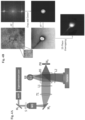
- the slides where then imaged using an IPM system which can be seen in Fig. 4A .
- the shown system consists of the ⁇ -Interferometer connected at the output of an inverted microscope.
- a supercontinuum fiber light source (SC-400-4 Fianium) connected to an acousto-optical tunable filter (SC-AOTF, Fianium) was used as the light source for the inverted microscope, emitting wavelengths of 532 ⁇ 3.1 nm.
- the beam first passes through the sample, then magnified using the microscope objective MO (63X, 1.4 NA, oil immersion, infinity-corrected) and passes through a spherical tube lens TL (150 mm focal length). Then, it passes through lens L1 (100 mm focal length) which Fourier transforms the beam, and beam splitter BS splits the beam into two separate beams.
- One beam passes straight through the beam splitter and then reflected back and shifted by retro-reflector RR.
- This beam is then reflected by the beam splitter and inverse Fourier transformed by lens L2 (150 mm focal length) onto a CMOS camera with 1280 X 1024 pixels (pixel size of 5.2 ⁇ m , DCC1545M, Thorlabs).
- This beam acts as the sample beam in this interferometric set-up.
- the second beam is reflected by the beam splitter onto a mirror-pinhole configuration, PH and M3, which spatially filters the beam, thus erasing the sample information, creating the reference beam.
- This beam is then reflected back and passes through the beam splitter where it is then inverse Fourier transformed by lens L2 and interferes with the sample beam on the camera.
- the final result is an off-axis interference pattern which is then transferred to the data processing utility 104 for further digital analysis.
- the sperm cells were imaged using the IPM system, they were stained using Quick Stain (Biological Industries) and left to dry for 15 minutes. Then, using the 2x2 point grid, the field of views captured using the IPM system were located once again and imaged using a brightfield microscope (Axio Observer D1, Ziess).
- ⁇ s and ⁇ r are the sample and reference beam phases respectively
- ⁇ is the
- the last two terms of the equation are the cross-correlation terms which are shifted relative to the DC term located in the center of the spatial frequency domain.
- Each cross-correlation term contains the complex wavefront of the sample which allows the extraction of the sperm cells' phase information.
- the reconstruction process of the phase images of the label-free sperm cells is illustrated in Fig. 4B .
- the holograms were cropped into smaller images of 256 X 256 pixels containing single cells.
- each sub-hologram was Fourier transformed to the spatial frequency domain where one of the cross-correlation terms was cropped and then inverse Fourier transformed into the complex wavefront of the sample beam.
- the phase information was extracted from the complex wavefront which then underwent a 2D phase unwrapping algorithm.
- Post processing of the phase images Two gradient images were created from each phase image. Those images were generated by shifting the phase images by one pixel in one of the spatial directions (x or y) and then subtracting the shifted image from the original phase image.
- a 256 X 256 hologram of a human sperm cell was used.
- the centered complex cross-correlation matrix was then transferred to a propagation algorithm.
- Rayleigh-Sommerfeld propagation of the angular spectrum as described by J.W. Goodman PROVIDE BIBLIOGRAPHIC DATA was used.
- the complex wavefront was propagated to different z-planes between -5 ⁇ m and 5 ⁇ m relative to the original focus plane at 0 ⁇ m . This was done in increments of 0.1 ⁇ m , such that 100 refocused complex wavefronts were generated.
- a phase image was generated from each propagated complex wavefront which enabled an optimal focused phase image to be chosen.
- the brightfield images of the stained sperm cells were cropped as well into a slightly larger field of view that still included the same single sperm cells that were imaged using the IPM system.
- each brightfield image was cross-correlated with the corresponding phase image of the same cell. This resulted in the location of the center of the required 256 X 256 field of view in the slightly larger brightfield images.
- the brightfield images were cropped into 256 X 256 images around the centers that were located using the cross-correlation of the two images, thus registering between the field of views of the phase images and the brightfield images. This resulted in two datasets, one containing the brightfield images of the stained sperm cells, and the other containing the phase images and GI images of the same sperm cells, where there is an exact overlap between the field of views of the two datasets.
- GAN framework was used in order to train a deep learning model to virtually stain sperm cells.
- This framework consisted of one generator model that was trained to create the virtually stained images from the phase and Gradient images of the cells, and a discriminator model that was trained to discriminate between generated and real stained images.
- the generator receives an input X which is a concatenation between the quantitative phase image and the two gradient images of the sperm cells and eventually generates output Z. It is trained to generate G which is a virtually stained image of the same sperm cell that was fed through the generator network.
- the discriminator Since the discriminator is trained to distinguish between generated and real stained images, in one case it receives D XY which indicates that the generator's input X is fed through the discriminator together with the chemically stained image of the sperm cell Y. In another case, the discriminator receives D XG which indicates that the generator's input X is fed through the discriminator together with the generated virtually stained image G.
- FIGs. 6A-6E An example of the virtual staining of unstained sperm cell, according to the technique of the invention, is shown in Figs. 6A-6E .
- Fig. 6A the reconstructed phase image of the label-free sperm cell is shown.
- Fig. 6B a gradient image with a shearing in the y direction is shown.
- Fig. 6C a gradient image with a shearing in the x direction is shown.
- Fig. 6D the actual Quick Stain staining of the sperm cell is shown.
- Fig. 6E the virtual staining of the label-free sperm cell which was created by the system of the invention is shown.
Landscapes
- Engineering & Computer Science (AREA)
- Theoretical Computer Science (AREA)
- General Physics & Mathematics (AREA)
- Physics & Mathematics (AREA)
- General Health & Medical Sciences (AREA)
- Health & Medical Sciences (AREA)
- Computer Vision & Pattern Recognition (AREA)
- Nuclear Medicine, Radiotherapy & Molecular Imaging (AREA)
- Quality & Reliability (AREA)
- Radiology & Medical Imaging (AREA)
- Medical Informatics (AREA)
- Life Sciences & Earth Sciences (AREA)
- Biomedical Technology (AREA)
- Molecular Biology (AREA)
- Multimedia (AREA)
- Investigating Or Analysing Biological Materials (AREA)
Claims (16)
- System zum Visualisieren einer ungefärbten Samenzelle, wobei das System umfasst:- ein Dateneingabeutility (102), das so konfiguriert und betreibbar ist, dass es gemessene Daten empfängt, die mindestens ein quantitatives Phasenmikroskopiebild der ungefärbten Samenzelle umfassen;- ein Datenverarbeitungsutility (104), umfassend:- ein Bildanalysemodul (104A), das so konfiguriert und betreibbar ist, dass es das mindestens ein quantitatives Phasenmikroskopiebild unter Verwendung charakteristischer Brechungsindexinformationen einer oder mehrerer Organellen der Samenzelle, die durch unterscheidbare Brechungsindexwerte verschiedener Organellen der Samenzelle in dem mindestens einen quantitativen Phasenmikroskopiebild dargestellt werden, verarbeitet und mindestens ein entsprechendes Gradientenbild erzeugt, das ein Differentialinterferenz-Kontrastbild ist, das eine Kantenverstärkung der einen oder mehreren Organellen einschließt; und- ein virtuelles Färbemodul (104B), das so konfiguriert und betreibbar ist, dass es eine oder mehrere vorbestimmte virtuelle Färbefunktionen, die eine spezifische Färbung betreffen, auf das mindestens eine quantitative Phasenmikroskopiebild und das mindestens eine entsprechende Gradientenbild anwendet, wobei die eine oder mehreren virtuellen Färbefunktionen durch ein trainiertes Deep-Learning-Modell vorbestimmt werden, das quantitative Phasenbilder der Samenzellen in virtuell gefärbte Bilder wandelt, um dadurch mindestens eine der einen oder mehreren Organellen der Samenzelle virtuell zu färben und virtuell gefärbte Bilddaten der Samenzelle zu erzeugen; und- ein Ausgabeutility (106), das so konfiguriert und betreibbar ist, dass es die virtuell gefärbten Bilddaten der Samenzelle verwendet und ein oder mehrere gefärbte Bilder der ungefärbten Samenzelle erzeugt, wobei jedes virtuelle Färbeattribute für die ungefärbte Samenzelle bereitstellt und dadurch ein Bild der Samenzelle emuliert, wenn die Samenzelle tatsächlich mit einer oder mehreren tatsächlichen Farben gefärbt wurde.
- System nach Anspruch 1, gekennzeichnet durch eines der folgenden(i) das Bildanalysemodul ist angepasst, um das mindestens eine quantitative Phasenmikroskopiebild zu verarbeiten und zwei entsprechende Gradientenbilder zu erzeugen, die Differentialinterferenz-Kontrastbilder sind, die jeweils einen Gradienten in einer der senkrechten Richtungen in dem quantitativen Phasenmikroskopiebild einschließen;(ii) das Dateneingabeutility empfängt die gemessenen Daten, ferner umfassend und mindestens ein Mikroskopiebild aus einem der folgenden: ein Differentialinterferenz-Kontrastmikroskopiebild, ein Hoffman-Mikroskopiebild und / oder ein Dunkelfeld-Mikroskopiebild der ungefärbten Samenzelle, und verwendet die mindestens einen quantitativen Phasenmikroskopiebilddaten und das mindestens eine Mikroskopiebild, um das mindestens eine Gradientenbild zu erzeugen.
- System nach Anspruch 1 oder 2, wobei das Datenverarbeitungsutility ein Modul zur Erzeugung einer virtuellen Färbefunktion umfasst, das so konfiguriert und betreibbar ist, dass es mindestens eine der einen oder mehreren virtuellen Färbefunktionen erzeugt, indem es Folgendes durchführt:Empfangen von ersten gemessenen Daten einer Vielzahl von quantitativen Phasenbildern einer jeweiligen Vielzahl von ungefärbten Samenzellen; und Empfangen von zweiten gemessenen Daten einer jeweiligen Vielzahl von Hellfeld-Mikroskopiebildern, die die Vielzahl der Hellfeld-Mikroskopiebilder der mit der spezifischen Farbe gefärbten Samenzellen umfassen; undVerarbeiten der ersten und zweiten gemessenen Daten unter Verwendung des Trainings eines maschinellen Lernmodells, um die mindestens eine virtuelle Färbefunktion zu erzeugen, die die spezifische Farbe betrifft.
- System nach Anspruch 3, wobei das maschinelle Deep-Learning eines oder mehrere der folgenden umfasst: Generative Adversarial Networks, Conditional Generative Adversarial Networks und Support-Vektor-Maschine.
- System nach einem der vorhergehenden Ansprüche, wobei die quantitativen Phasenbilddaten der ungefärbten Samenzelle digitale holographische mikroskopische Bilddaten der ungefärbten Samenzelle umfassen.
- System nach einem der vorhergehenden Ansprüche, wobei das Ausgabeutility so konfiguriert und betreibbar ist, dass es gleichzeitig oder intermittierend eine Vielzahl von gefärbten Bildern der ungefärbten Samenzelle anzeigt, wobei jedes gefärbte Bild durch eine Farbe oder eine Organelle in der ungefärbten Samenzelle gekennzeichnet ist.
- System nach einem der vorhergehenden Ansprüche, wobei das Datenverarbeitungsutility ein Modul zur Bestimmung der Samenmorphologie umfasst, das so konfiguriert und betreibbar ist, dass es das eine oder die mehreren gefärbten Bilder der ungefärbten Samenzelle verarbeitet und einen oder mehrere morphologische Parameter der Samenzelle bestimmt.
- System nach einem der vorhergehenden Ansprüche, das ferner mindestens eines der folgenden umfasst: ein quantitatives Phasenmikroskop, das so konfiguriert und betreibbar ist, dass es die ungefärbte Samenzelle abbildet und die quantitativen Phasenbilddaten der ungefärbten Samenzelle bereitstellt; und eine Samensortiereinrichtung, die so konfiguriert und betreibbar ist, dass sie die Auswahl mindestens einer Samenzelle aus einer Vielzahl von Samenzellen ermöglicht, die durch das System sichtbar gemacht werden, wobei die Samensortiereinrichtung einen Einsatz umfasst, der die Vielzahl von Samenzellen aufnimmt und die individuelle Trennung und / oder Auswahl der mindestens einen Samenzelle ermöglicht.
- System nach Anspruch 8, wobei es sich bei dem quantitativen Phasenmikroskop um ein digitales holographisches Mikroskop handelt, das zur Abbildung der ungefärbten Samenzelle und zur Bereitstellung der quantitativen Phasenbilddaten der ungefärbten Samenzelle angepasst ist.
- System nach einem der vorhergehenden Ansprüche, das ferner eine Samensortiereinrichtung umfasst, die so konfiguriert und betreibbar ist, dass sie die Auswahl von mindestens einer Samenzelle aus einer Vielzahl von Samenzellen ermöglicht, die von dem System visualisiert werden, wobei die Samensortiereinrichtung einen Einsatz zur Aufnahme der Vielzahl von Samenzellen umfasst und die individuelle Trennung und / oder Auswahl der mindestens einen Samenzelle ermöglicht, wobei der Einsatz eine oder mehrere Zellfallen umfasst, die die individuelle Trennung und / oder Auswahl der mindestens einen Samenzelle ermöglichen.
- Verfahren zum Visualisieren einer ungefärbten Samenzelle, wobei das Verfahren umfasst:- Empfangen von Daten, umfassend: gemessene Daten, die mindestens ein quantitatives Phasenmikroskopiebild der ungefärbten Samenzelle umfassen; Daten, die charakteristische Brechungsindexinformationen von einer oder mehreren Organellen der Samenzelle anzeigen; und Daten, die eine oder mehrere virtuelle Färbefunktionen anzeigen, die jeweils eine oder mehrere tatsächliche Farben betreffen, die typischerweise zum Färben der einen oder mehreren Organellen der Samenzelle verwendet werden;- Verarbeiten des quantitativen Phasenmikroskopiebildes der Samenzelle durch Verwenden der charakteristischen Brechungsindexinformation, die durch unterscheidbare Brechungsindexwerte verschiedener Organellen der Samenzelle in dem mindestens einen quantitativen Phasenmikroskopiebild dargestellt werden, und Erzeugen mindestens eines entsprechenden Gradientenbildes, das ein Differentialinterferenz-Kontrastbild ist, das eine Kantenverstärkung der einen oder mehreren Organellen einschließt;- Verarbeiten des mindestens einen quantitativen Phasenmikroskopiebildes und des mindestens einen entsprechenden Gradientenbildes durch Verwenden der einen oder mehreren virtuellen Färbefunktionen, betreffend eine spezifische Farbe und vorbestimmt durch ein trainiertes Deep-Learning-Modell, das quantitative Phasenbilder der Samenzellen in virtuell gefärbte Bilder wandelt, um dadurch mindestens eine der einen oder mehreren Organellen der Samenzelle virtuell zu färben und virtuell gefärbte Bilddaten der Samenzelle zu erzeugen; und- Erzeugen eines oder mehrerer gefärbter Bilder der ungefärbten Samenzelle aus den virtuell gefärbten Bilddaten der Samenzelle, wobei jedes gefärbte Bild virtuelle Färbeattribute für die ungefärbte Samenzelle bereitstellt und dadurch ein Bild der Samenzelle emuliert, wenn die Samenzelle tatsächlich mit einer oder mehreren der einen oder mehreren Farben gefärbt wurde.
- Verfahren nach Anspruch 11, wobei die Verarbeitung des mindestens einen quantitativen Phasenmikroskopiebildes zwei entsprechende Gradientenbilder bereitstellt, die Differentialinterferenz-Kontrastbilder sind, wobei jedes einen Gradienten in einer der senkrechten Richtungen in dem quantitativen Phasenmikroskopiebild einschließt.
- Verfahren nach Anspruch 11 oder 12, wobei das Empfangen der gemessenen Daten ferner das Empfangen mindestens eines Mikroskopiebildes aus einem der folgenden umfasst: ein Differentialinterferenzkontrast-Mikroskopiebild, ein Hoffman-Mikroskopiebild und / oder ein Dunkelfeld-Mikroskopiebild der ungefärbten Samenzelle, wobei das Verfahren ferner die Verwendung des mindestens einen Mikroskopiebildes zur Erzeugung des Gradientenbildes umfasst.
- Verfahren nach einem der Ansprüche 11 bis 13, ferner umfassend das Erzeugen mindestens einer der einen oder mehreren virtuellen Färbefunktionen durch Ausführen des Folgenden: Empfangen von ersten gemessenen Daten einer Vielzahl von quantitativen Phasenbildern einer jeweiligen Vielzahl von ungefärbten Samenzellen; Empfangen von zweiten gemessenen Daten einer jeweiligen Vielzahl von Hellfeld-Mikroskopiebildern der mit der spezifischen Farbe gefärbten Samenzellen; und Verarbeiten der ersten und zweiten gemessenen Daten unter Verwendung des Trainings eines maschinellen Lernmodells, um die mindestens eine virtuelle Färbefunktion zu erzeugen, die die spezifische Farbe betrifft.
- Verfahren nach einem der Ansprüche 11 bis 14, wobei die ungefärbte Samenzelle eine Spermatiden- oder Spermatozoen-Zelle ist, die eine oder mehreren Organellen der Zelle eine oder mehrere der folgenden umfassen: Kern, Akrosom, Mitochondrien, Vakuole und Zytoplasma, wobei eine oder mehrere tatsächliche Farben aus den folgenden ausgewählt werden: Nigrosin-Eosin, Toluidinblau, Hämatoxylin-Eosin, Hämatoxylin und Eosin (H&E), EA50, OG6, Papanicolaou-Farbe und Coomassie G250.
- Verfahren nach einem der Ansprüche 11 bis 15, ferner umfassend mindestens eines des folgenden: Verarbeiten des einen oder der mehreren gefärbten Bilder der ungefärbten Samenzelle und Bestimmen eines oder mehrerer morphologischer Parameter der Samenzelle; und Auswählen mindestens einer ungefärbten Samenzelle aus einer Vielzahl von visualisierten ungefärbten Samenzellen.
Applications Claiming Priority (2)
| Application Number | Priority Date | Filing Date | Title |
|---|---|---|---|
| US201862691778P | 2018-06-29 | 2018-06-29 | |
| PCT/IB2019/055451 WO2020003194A1 (en) | 2018-06-29 | 2019-06-27 | Virtual staining systems and methods for observing one or more unstained cells |
Publications (3)
| Publication Number | Publication Date |
|---|---|
| EP3811331A1 EP3811331A1 (de) | 2021-04-28 |
| EP3811331A4 EP3811331A4 (de) | 2022-04-06 |
| EP3811331B1 true EP3811331B1 (de) | 2024-02-07 |
Family
ID=68984978
Family Applications (1)
| Application Number | Title | Priority Date | Filing Date |
|---|---|---|---|
| EP19827327.8A Active EP3811331B1 (de) | 2018-06-29 | 2019-06-27 | Virtuelle färbesysteme und verfahren zur beobachtung von einer oder mehreren ungefärbten zellen |
Country Status (3)
| Country | Link |
|---|---|
| US (1) | US11948295B2 (de) |
| EP (1) | EP3811331B1 (de) |
| WO (1) | WO2020003194A1 (de) |
Families Citing this family (11)
| Publication number | Priority date | Publication date | Assignee | Title |
|---|---|---|---|---|
| US12327621B2 (en) * | 2019-07-31 | 2025-06-10 | Spinshell, Inc. | Reporting device, reporting method, reporting program, and reporting system |
| US11501420B2 (en) * | 2019-09-26 | 2022-11-15 | Perkinelmer Cellular Technologies Germany Gmbh | Reconstructing phase images with deep learning |
| EP3828617A1 (de) * | 2019-11-26 | 2021-06-02 | Siemens Healthcare Diagnostics Inc. | Verfahren zur digitalen anfärbung von zellen |
| EP4211657B1 (de) * | 2020-09-08 | 2024-12-11 | Insitro, Inc. | Umwandlung biologischer bilder unter verwendung von maschinenlernmodellen |
| WO2022096406A1 (en) | 2020-11-04 | 2022-05-12 | Renescience A/S | Method for enzymatic and/or microbial processing of waste comprising recirculation of process water |
| EP4177826A1 (de) * | 2021-11-05 | 2023-05-10 | Technische Universität Dresden | Verfahren und system zur simulation und vorhersage der histologischen färbung eines gewebeschnitts |
| CN114820872B (zh) * | 2022-03-11 | 2025-08-01 | 南京理工大学 | 一种免化学染色的高活性精子检测方法 |
| TWI811069B (zh) * | 2022-08-19 | 2023-08-01 | 倍利科技股份有限公司 | 基於影像識別偵測特定細胞之系統及方法 |
| US12094570B2 (en) * | 2022-10-21 | 2024-09-17 | David Charles Epstein | Machine learning characterization of sperm quality for sperm selection for assisted reproduction technology |
| CN116912155A (zh) * | 2022-11-28 | 2023-10-20 | 苏州博致医疗科技有限公司 | 一种准确测量活精子形态的方法 |
| EP4731105A1 (de) * | 2023-06-26 | 2026-04-29 | Conceivable Life Sciences, Inc. | Intelligente automatisierte in-vitro-befruchtung und hintergrund einer intrazytoplasmischen spermainjektionsplattform |
Family Cites Families (9)
| Publication number | Priority date | Publication date | Assignee | Title |
|---|---|---|---|---|
| US7526116B2 (en) * | 2006-01-19 | 2009-04-28 | Luigi Armogida | Automated microscopic sperm identification |
| US8340389B2 (en) | 2008-11-26 | 2012-12-25 | Agilent Technologies, Inc. | Cellular- or sub-cellular-based visualization information using virtual stains |
| WO2012078796A1 (en) * | 2010-12-07 | 2012-06-14 | Life Technologies Corporation | Virtual cellular staining |
| WO2013142366A1 (en) * | 2012-03-19 | 2013-09-26 | Genetic Innovations, Inc. | Devices, systems, and methods for virtual staining |
| US9574868B2 (en) | 2012-03-21 | 2017-02-21 | Ramot At Tel-Aviv University Ltd. | Portable interferometric device |
| DE102014200911A1 (de) * | 2013-10-09 | 2015-04-09 | Siemens Aktiengesellschaft | In-Vitro-Verfahren zum markierungsfreien Bestimmen eines Zelltyps einer Zelle |
| US20200222907A1 (en) * | 2017-04-26 | 2020-07-16 | DxNow, Inc. | Systems and methods for determining probative samples and isolation and quantitation of cells |
| WO2016178234A1 (en) * | 2015-05-07 | 2016-11-10 | Technology Innovation Momentum Fund (Israel) Limited Partnership | Interferometric system and method for use with biological cells and organisms including sperm |
| EP3867869A1 (de) * | 2018-10-18 | 2021-08-25 | Verily Life Sciences LLC | Systeme und verfahren zur verwendung von bildverarbeitung zur erzeugung von biomarkerableitungen für immuntherapie |
-
2019
- 2019-06-27 EP EP19827327.8A patent/EP3811331B1/de active Active
- 2019-06-27 US US17/256,373 patent/US11948295B2/en active Active
- 2019-06-27 WO PCT/IB2019/055451 patent/WO2020003194A1/en not_active Ceased
Also Published As
| Publication number | Publication date |
|---|---|
| US20210158521A1 (en) | 2021-05-27 |
| EP3811331A4 (de) | 2022-04-06 |
| WO2020003194A1 (en) | 2020-01-02 |
| EP3811331A1 (de) | 2021-04-28 |
| US11948295B2 (en) | 2024-04-02 |
Similar Documents
| Publication | Publication Date | Title |
|---|---|---|
| EP3811331B1 (de) | Virtuelle färbesysteme und verfahren zur beobachtung von einer oder mehreren ungefärbten zellen | |
| Mirsky et al. | Automated analysis of individual sperm cells using stain‐free interferometric phase microscopy and machine learning | |
| Park et al. | Artificial intelligence-enabled quantitative phase imaging methods for life sciences | |
| EP3292406B1 (de) | Interferometrisches system und verfahren zur verwendung mit biologischen zellen und organismen, einschliesslich sperma | |
| US12106552B2 (en) | Method and system for digital staining of label-free phase images using deep learning | |
| Amann et al. | Computer-assisted sperm analysis (CASA): Capabilities and potential developments | |
| US20220383986A1 (en) | Complex System for Contextual Spectrum Mask Generation Based on Quantitative Imaging | |
| Haifler et al. | Interferometric phase microscopy for label-free morphological evaluation of sperm cells | |
| Merola et al. | Digital holography as a method for 3D imaging and estimating the biovolume of motile cells | |
| Noy et al. | Sperm‐cell DNA fragmentation prediction using label‐free quantitative phase imaging and deep learning | |
| US20080032325A1 (en) | Phase subtraction cell counting method | |
| US12067712B2 (en) | Complex system for contextual mask generation based on quantitative imaging | |
| Balberg et al. | Localized measurements of physical parameters within human sperm cells obtained with wide‐field interferometry | |
| De Angelis et al. | Combined Raman spectroscopy and digital holographic microscopy for sperm cell quality analysis | |
| Moon et al. | Cell identification computational 3-D holographic microscopy | |
| JP7688991B2 (ja) | 受精卵の発生ステージ判定方法、プログラム、記録媒体、撮像方法および撮像装置 | |
| Bhatt et al. | Characterizing the consistency of motion of spermatozoa through nanoscale motion tracing | |
| CN114326075A (zh) | 一种生物样品的数字显微成像系统及镜检方法 | |
| Poola et al. | Quantitative label-free technique for morphological evaluation of human sperm—a promising tool in semen evaluation | |
| EP3746783B1 (de) | Verfahren und system zur bewertung der fruchtbarkeit von menschlichen spermatozoen | |
| Wheeler et al. | Label-free, high-throughput holographic imaging to evaluate mammalian gametes and embryos | |
| EP2781945A1 (de) | Verfahren zum Bewerten der Morphologie von Espermatozoa und System dafür | |
| Yao et al. | Automatic three-dimensional imaging for blastomere identification in early-stage embryos based on brightfield microscopy | |
| Chung et al. | Quantitative absorption tomography | |
| Poola et al. | Quantitative label-free sperm imaging by means of transport of intensity |
Legal Events
| Date | Code | Title | Description |
|---|---|---|---|
| STAA | Information on the status of an ep patent application or granted ep patent |
Free format text: STATUS: THE INTERNATIONAL PUBLICATION HAS BEEN MADE |
|
| PUAI | Public reference made under article 153(3) epc to a published international application that has entered the european phase |
Free format text: ORIGINAL CODE: 0009012 |
|
| STAA | Information on the status of an ep patent application or granted ep patent |
Free format text: STATUS: REQUEST FOR EXAMINATION WAS MADE |
|
| 17P | Request for examination filed |
Effective date: 20210121 |
|
| AK | Designated contracting states |
Kind code of ref document: A1 Designated state(s): AL AT BE BG CH CY CZ DE DK EE ES FI FR GB GR HR HU IE IS IT LI LT LU LV MC MK MT NL NO PL PT RO RS SE SI SK SM TR |
|
| AX | Request for extension of the european patent |
Extension state: BA ME |
|
| DAV | Request for validation of the european patent (deleted) | ||
| DAX | Request for extension of the european patent (deleted) | ||
| REG | Reference to a national code |
Ref legal event code: R079 Ipc: G06V0020690000 Ref country code: DE Ref legal event code: R079 Ref document number: 602019046255 Country of ref document: DE Free format text: PREVIOUS MAIN CLASS: G06T0007000000 Ipc: G06V0020690000 |
|
| A4 | Supplementary search report drawn up and despatched |
Effective date: 20220304 |
|
| RIC1 | Information provided on ipc code assigned before grant |
Ipc: G06T 5/00 20060101ALI20220301BHEP Ipc: G06T 7/00 20170101ALI20220301BHEP Ipc: G06V 20/69 20220101AFI20220301BHEP |
|
| GRAP | Despatch of communication of intention to grant a patent |
Free format text: ORIGINAL CODE: EPIDOSNIGR1 |
|
| STAA | Information on the status of an ep patent application or granted ep patent |
Free format text: STATUS: GRANT OF PATENT IS INTENDED |
|
| INTG | Intention to grant announced |
Effective date: 20230915 |
|
| GRAS | Grant fee paid |
Free format text: ORIGINAL CODE: EPIDOSNIGR3 |
|
| GRAA | (expected) grant |
Free format text: ORIGINAL CODE: 0009210 |
|
| STAA | Information on the status of an ep patent application or granted ep patent |
Free format text: STATUS: THE PATENT HAS BEEN GRANTED |
|
| AK | Designated contracting states |
Kind code of ref document: B1 Designated state(s): AL AT BE BG CH CY CZ DE DK EE ES FI FR GB GR HR HU IE IS IT LI LT LU LV MC MK MT NL NO PL PT RO RS SE SI SK SM TR |
|
| REG | Reference to a national code |
Ref country code: GB Ref legal event code: FG4D |
|
| REG | Reference to a national code |
Ref country code: CH Ref legal event code: EP |
|
| P01 | Opt-out of the competence of the unified patent court (upc) registered |
Effective date: 20240123 |
|
| REG | Reference to a national code |
Ref country code: IE Ref legal event code: FG4D |
|
| REG | Reference to a national code |
Ref country code: DE Ref legal event code: R096 Ref document number: 602019046255 Country of ref document: DE |
|
| REG | Reference to a national code |
Ref country code: LT Ref legal event code: MG9D |
|
| REG | Reference to a national code |
Ref country code: NL Ref legal event code: MP Effective date: 20240207 |
|
| PG25 | Lapsed in a contracting state [announced via postgrant information from national office to epo] |
Ref country code: IS Free format text: LAPSE BECAUSE OF FAILURE TO SUBMIT A TRANSLATION OF THE DESCRIPTION OR TO PAY THE FEE WITHIN THE PRESCRIBED TIME-LIMIT Effective date: 20240607 |
|
| PG25 | Lapsed in a contracting state [announced via postgrant information from national office to epo] |
Ref country code: LT Free format text: LAPSE BECAUSE OF FAILURE TO SUBMIT A TRANSLATION OF THE DESCRIPTION OR TO PAY THE FEE WITHIN THE PRESCRIBED TIME-LIMIT Effective date: 20240207 |
|
| PG25 | Lapsed in a contracting state [announced via postgrant information from national office to epo] |
Ref country code: GR Free format text: LAPSE BECAUSE OF FAILURE TO SUBMIT A TRANSLATION OF THE DESCRIPTION OR TO PAY THE FEE WITHIN THE PRESCRIBED TIME-LIMIT Effective date: 20240508 |
|
| REG | Reference to a national code |
Ref country code: AT Ref legal event code: MK05 Ref document number: 1655848 Country of ref document: AT Kind code of ref document: T Effective date: 20240207 |
|
| PG25 | Lapsed in a contracting state [announced via postgrant information from national office to epo] |
Ref country code: HR Free format text: LAPSE BECAUSE OF FAILURE TO SUBMIT A TRANSLATION OF THE DESCRIPTION OR TO PAY THE FEE WITHIN THE PRESCRIBED TIME-LIMIT Effective date: 20240207 Ref country code: NL Free format text: LAPSE BECAUSE OF FAILURE TO SUBMIT A TRANSLATION OF THE DESCRIPTION OR TO PAY THE FEE WITHIN THE PRESCRIBED TIME-LIMIT Effective date: 20240207 Ref country code: RS Free format text: LAPSE BECAUSE OF FAILURE TO SUBMIT A TRANSLATION OF THE DESCRIPTION OR TO PAY THE FEE WITHIN THE PRESCRIBED TIME-LIMIT Effective date: 20240507 |
|
| PG25 | Lapsed in a contracting state [announced via postgrant information from national office to epo] |
Ref country code: ES Free format text: LAPSE BECAUSE OF FAILURE TO SUBMIT A TRANSLATION OF THE DESCRIPTION OR TO PAY THE FEE WITHIN THE PRESCRIBED TIME-LIMIT Effective date: 20240207 |
|
| PG25 | Lapsed in a contracting state [announced via postgrant information from national office to epo] |
Ref country code: AT Free format text: LAPSE BECAUSE OF FAILURE TO SUBMIT A TRANSLATION OF THE DESCRIPTION OR TO PAY THE FEE WITHIN THE PRESCRIBED TIME-LIMIT Effective date: 20240207 |
|
| PG25 | Lapsed in a contracting state [announced via postgrant information from national office to epo] |
Ref country code: RS Free format text: LAPSE BECAUSE OF FAILURE TO SUBMIT A TRANSLATION OF THE DESCRIPTION OR TO PAY THE FEE WITHIN THE PRESCRIBED TIME-LIMIT Effective date: 20240507 Ref country code: NO Free format text: LAPSE BECAUSE OF FAILURE TO SUBMIT A TRANSLATION OF THE DESCRIPTION OR TO PAY THE FEE WITHIN THE PRESCRIBED TIME-LIMIT Effective date: 20240507 Ref country code: NL Free format text: LAPSE BECAUSE OF FAILURE TO SUBMIT A TRANSLATION OF THE DESCRIPTION OR TO PAY THE FEE WITHIN THE PRESCRIBED TIME-LIMIT Effective date: 20240207 Ref country code: LT Free format text: LAPSE BECAUSE OF FAILURE TO SUBMIT A TRANSLATION OF THE DESCRIPTION OR TO PAY THE FEE WITHIN THE PRESCRIBED TIME-LIMIT Effective date: 20240207 Ref country code: IS Free format text: LAPSE BECAUSE OF FAILURE TO SUBMIT A TRANSLATION OF THE DESCRIPTION OR TO PAY THE FEE WITHIN THE PRESCRIBED TIME-LIMIT Effective date: 20240607 Ref country code: HR Free format text: LAPSE BECAUSE OF FAILURE TO SUBMIT A TRANSLATION OF THE DESCRIPTION OR TO PAY THE FEE WITHIN THE PRESCRIBED TIME-LIMIT Effective date: 20240207 Ref country code: GR Free format text: LAPSE BECAUSE OF FAILURE TO SUBMIT A TRANSLATION OF THE DESCRIPTION OR TO PAY THE FEE WITHIN THE PRESCRIBED TIME-LIMIT Effective date: 20240508 Ref country code: FI Free format text: LAPSE BECAUSE OF FAILURE TO SUBMIT A TRANSLATION OF THE DESCRIPTION OR TO PAY THE FEE WITHIN THE PRESCRIBED TIME-LIMIT Effective date: 20240207 Ref country code: ES Free format text: LAPSE BECAUSE OF FAILURE TO SUBMIT A TRANSLATION OF THE DESCRIPTION OR TO PAY THE FEE WITHIN THE PRESCRIBED TIME-LIMIT Effective date: 20240207 Ref country code: BG Free format text: LAPSE BECAUSE OF FAILURE TO SUBMIT A TRANSLATION OF THE DESCRIPTION OR TO PAY THE FEE WITHIN THE PRESCRIBED TIME-LIMIT Effective date: 20240207 Ref country code: AT Free format text: LAPSE BECAUSE OF FAILURE TO SUBMIT A TRANSLATION OF THE DESCRIPTION OR TO PAY THE FEE WITHIN THE PRESCRIBED TIME-LIMIT Effective date: 20240207 |
|
| PG25 | Lapsed in a contracting state [announced via postgrant information from national office to epo] |
Ref country code: PT Free format text: LAPSE BECAUSE OF FAILURE TO SUBMIT A TRANSLATION OF THE DESCRIPTION OR TO PAY THE FEE WITHIN THE PRESCRIBED TIME-LIMIT Effective date: 20240607 Ref country code: PL Free format text: LAPSE BECAUSE OF FAILURE TO SUBMIT A TRANSLATION OF THE DESCRIPTION OR TO PAY THE FEE WITHIN THE PRESCRIBED TIME-LIMIT Effective date: 20240207 |
|
| PG25 | Lapsed in a contracting state [announced via postgrant information from national office to epo] |
Ref country code: SE Free format text: LAPSE BECAUSE OF FAILURE TO SUBMIT A TRANSLATION OF THE DESCRIPTION OR TO PAY THE FEE WITHIN THE PRESCRIBED TIME-LIMIT Effective date: 20240207 Ref country code: PT Free format text: LAPSE BECAUSE OF FAILURE TO SUBMIT A TRANSLATION OF THE DESCRIPTION OR TO PAY THE FEE WITHIN THE PRESCRIBED TIME-LIMIT Effective date: 20240607 Ref country code: PL Free format text: LAPSE BECAUSE OF FAILURE TO SUBMIT A TRANSLATION OF THE DESCRIPTION OR TO PAY THE FEE WITHIN THE PRESCRIBED TIME-LIMIT Effective date: 20240207 Ref country code: LV Free format text: LAPSE BECAUSE OF FAILURE TO SUBMIT A TRANSLATION OF THE DESCRIPTION OR TO PAY THE FEE WITHIN THE PRESCRIBED TIME-LIMIT Effective date: 20240207 |
|
| PG25 | Lapsed in a contracting state [announced via postgrant information from national office to epo] |
Ref country code: DK Free format text: LAPSE BECAUSE OF FAILURE TO SUBMIT A TRANSLATION OF THE DESCRIPTION OR TO PAY THE FEE WITHIN THE PRESCRIBED TIME-LIMIT Effective date: 20240207 |
|
| PG25 | Lapsed in a contracting state [announced via postgrant information from national office to epo] |
Ref country code: SM Free format text: LAPSE BECAUSE OF FAILURE TO SUBMIT A TRANSLATION OF THE DESCRIPTION OR TO PAY THE FEE WITHIN THE PRESCRIBED TIME-LIMIT Effective date: 20240207 |
|
| PG25 | Lapsed in a contracting state [announced via postgrant information from national office to epo] |
Ref country code: CZ Free format text: LAPSE BECAUSE OF FAILURE TO SUBMIT A TRANSLATION OF THE DESCRIPTION OR TO PAY THE FEE WITHIN THE PRESCRIBED TIME-LIMIT Effective date: 20240207 Ref country code: EE Free format text: LAPSE BECAUSE OF FAILURE TO SUBMIT A TRANSLATION OF THE DESCRIPTION OR TO PAY THE FEE WITHIN THE PRESCRIBED TIME-LIMIT Effective date: 20240207 |
|
| PG25 | Lapsed in a contracting state [announced via postgrant information from national office to epo] |
Ref country code: SK Free format text: LAPSE BECAUSE OF FAILURE TO SUBMIT A TRANSLATION OF THE DESCRIPTION OR TO PAY THE FEE WITHIN THE PRESCRIBED TIME-LIMIT Effective date: 20240207 |
|
| PG25 | Lapsed in a contracting state [announced via postgrant information from national office to epo] |
Ref country code: SM Free format text: LAPSE BECAUSE OF FAILURE TO SUBMIT A TRANSLATION OF THE DESCRIPTION OR TO PAY THE FEE WITHIN THE PRESCRIBED TIME-LIMIT Effective date: 20240207 Ref country code: SK Free format text: LAPSE BECAUSE OF FAILURE TO SUBMIT A TRANSLATION OF THE DESCRIPTION OR TO PAY THE FEE WITHIN THE PRESCRIBED TIME-LIMIT Effective date: 20240207 Ref country code: RO Free format text: LAPSE BECAUSE OF FAILURE TO SUBMIT A TRANSLATION OF THE DESCRIPTION OR TO PAY THE FEE WITHIN THE PRESCRIBED TIME-LIMIT Effective date: 20240207 Ref country code: EE Free format text: LAPSE BECAUSE OF FAILURE TO SUBMIT A TRANSLATION OF THE DESCRIPTION OR TO PAY THE FEE WITHIN THE PRESCRIBED TIME-LIMIT Effective date: 20240207 Ref country code: DK Free format text: LAPSE BECAUSE OF FAILURE TO SUBMIT A TRANSLATION OF THE DESCRIPTION OR TO PAY THE FEE WITHIN THE PRESCRIBED TIME-LIMIT Effective date: 20240207 Ref country code: CZ Free format text: LAPSE BECAUSE OF FAILURE TO SUBMIT A TRANSLATION OF THE DESCRIPTION OR TO PAY THE FEE WITHIN THE PRESCRIBED TIME-LIMIT Effective date: 20240207 |
|
| REG | Reference to a national code |
Ref country code: DE Ref legal event code: R097 Ref document number: 602019046255 Country of ref document: DE |
|
| PG25 | Lapsed in a contracting state [announced via postgrant information from national office to epo] |
Ref country code: IT Free format text: LAPSE BECAUSE OF FAILURE TO SUBMIT A TRANSLATION OF THE DESCRIPTION OR TO PAY THE FEE WITHIN THE PRESCRIBED TIME-LIMIT Effective date: 20240207 |
|
| PLBE | No opposition filed within time limit |
Free format text: ORIGINAL CODE: 0009261 |
|
| STAA | Information on the status of an ep patent application or granted ep patent |
Free format text: STATUS: NO OPPOSITION FILED WITHIN TIME LIMIT |
|
| PG25 | Lapsed in a contracting state [announced via postgrant information from national office to epo] |
Ref country code: IT Free format text: LAPSE BECAUSE OF FAILURE TO SUBMIT A TRANSLATION OF THE DESCRIPTION OR TO PAY THE FEE WITHIN THE PRESCRIBED TIME-LIMIT Effective date: 20240207 |
|
| 26N | No opposition filed |
Effective date: 20241108 |
|
| PG25 | Lapsed in a contracting state [announced via postgrant information from national office to epo] |
Ref country code: MC Free format text: LAPSE BECAUSE OF FAILURE TO SUBMIT A TRANSLATION OF THE DESCRIPTION OR TO PAY THE FEE WITHIN THE PRESCRIBED TIME-LIMIT Effective date: 20240207 |
|
| PG25 | Lapsed in a contracting state [announced via postgrant information from national office to epo] |
Ref country code: LU Free format text: LAPSE BECAUSE OF NON-PAYMENT OF DUE FEES Effective date: 20240627 |
|
| PG25 | Lapsed in a contracting state [announced via postgrant information from national office to epo] |
Ref country code: IE Free format text: LAPSE BECAUSE OF NON-PAYMENT OF DUE FEES Effective date: 20240627 |
|
| PG25 | Lapsed in a contracting state [announced via postgrant information from national office to epo] |
Ref country code: BE Free format text: LAPSE BECAUSE OF NON-PAYMENT OF DUE FEES Effective date: 20240630 Ref country code: SI Free format text: LAPSE BECAUSE OF FAILURE TO SUBMIT A TRANSLATION OF THE DESCRIPTION OR TO PAY THE FEE WITHIN THE PRESCRIBED TIME-LIMIT Effective date: 20240207 |
|
| REG | Reference to a national code |
Ref country code: BE Ref legal event code: MM Effective date: 20240630 |
|
| PGFP | Annual fee paid to national office [announced via postgrant information from national office to epo] |
Ref country code: DE Payment date: 20250919 Year of fee payment: 7 |
|
| PGFP | Annual fee paid to national office [announced via postgrant information from national office to epo] |
Ref country code: GB Payment date: 20250918 Year of fee payment: 7 |
|
| PGFP | Annual fee paid to national office [announced via postgrant information from national office to epo] |
Ref country code: FR Payment date: 20250919 Year of fee payment: 7 |
|
| PGFP | Annual fee paid to national office [announced via postgrant information from national office to epo] |
Ref country code: CH Payment date: 20250908 Year of fee payment: 7 |
|
| PG25 | Lapsed in a contracting state [announced via postgrant information from national office to epo] |
Ref country code: CY Free format text: LAPSE BECAUSE OF FAILURE TO SUBMIT A TRANSLATION OF THE DESCRIPTION OR TO PAY THE FEE WITHIN THE PRESCRIBED TIME-LIMIT; INVALID AB INITIO Effective date: 20190627 |
|
| PG25 | Lapsed in a contracting state [announced via postgrant information from national office to epo] |
Ref country code: HU Free format text: LAPSE BECAUSE OF FAILURE TO SUBMIT A TRANSLATION OF THE DESCRIPTION OR TO PAY THE FEE WITHIN THE PRESCRIBED TIME-LIMIT; INVALID AB INITIO Effective date: 20190627 |