EP4517459A1 - Production system, production system management method, and program recording medium having program for production system management device recorded thereon - Google Patents
Production system, production system management method, and program recording medium having program for production system management device recorded thereon Download PDFInfo
- Publication number
- EP4517459A1 EP4517459A1 EP23803466.4A EP23803466A EP4517459A1 EP 4517459 A1 EP4517459 A1 EP 4517459A1 EP 23803466 A EP23803466 A EP 23803466A EP 4517459 A1 EP4517459 A1 EP 4517459A1
- Authority
- EP
- European Patent Office
- Prior art keywords
- task
- power level
- automated work
- work apparatus
- automated
- Prior art date
- Legal status (The legal status is an assumption and is not a legal conclusion. Google has not performed a legal analysis and makes no representation as to the accuracy of the status listed.)
- Pending
Links
Images





Classifications
-
- B—PERFORMING OPERATIONS; TRANSPORTING
- B25—HAND TOOLS; PORTABLE POWER-DRIVEN TOOLS; MANIPULATORS
- B25J—MANIPULATORS; CHAMBERS PROVIDED WITH MANIPULATION DEVICES
- B25J9/00—Program-controlled manipulators
- B25J9/16—Program controls
- B25J9/1656—Program controls characterised by programming, planning systems for manipulators
- B25J9/1661—Program controls characterised by programming, planning systems for manipulators characterised by task planning, object-oriented languages
-
- G—PHYSICS
- G05—CONTROLLING; REGULATING
- G05B—CONTROL OR REGULATING SYSTEMS IN GENERAL; FUNCTIONAL ELEMENTS OF SUCH SYSTEMS; MONITORING OR TESTING ARRANGEMENTS FOR SUCH SYSTEMS OR ELEMENTS
- G05B19/00—Program-control systems
- G05B19/02—Program-control systems electric
- G05B19/418—Total factory control, i.e. centrally controlling a plurality of machines, e.g. direct or distributed numerical control [DNC], flexible manufacturing systems [FMS], integrated manufacturing systems [IMS] or computer integrated manufacturing [CIM]
- G05B19/41815—Total factory control, i.e. centrally controlling a plurality of machines, e.g. direct or distributed numerical control [DNC], flexible manufacturing systems [FMS], integrated manufacturing systems [IMS] or computer integrated manufacturing [CIM] characterised by the cooperation between machine tools, manipulators and conveyor or other workpiece supply system, workcell
- G05B19/41825—Total factory control, i.e. centrally controlling a plurality of machines, e.g. direct or distributed numerical control [DNC], flexible manufacturing systems [FMS], integrated manufacturing systems [IMS] or computer integrated manufacturing [CIM] characterised by the cooperation between machine tools, manipulators and conveyor or other workpiece supply system, workcell machine tools and manipulators only, machining centre
-
- B—PERFORMING OPERATIONS; TRANSPORTING
- B25—HAND TOOLS; PORTABLE POWER-DRIVEN TOOLS; MANIPULATORS
- B25J—MANIPULATORS; CHAMBERS PROVIDED WITH MANIPULATION DEVICES
- B25J19/00—Accessories fitted to manipulators, e.g. for monitoring, for viewing; Safety devices combined with or specially adapted for use in connection with manipulators
- B25J19/005—Accessories fitted to manipulators, e.g. for monitoring, for viewing; Safety devices combined with or specially adapted for use in connection with manipulators using batteries, e.g. as a back-up power source
-
- B—PERFORMING OPERATIONS; TRANSPORTING
- B25—HAND TOOLS; PORTABLE POWER-DRIVEN TOOLS; MANIPULATORS
- B25J—MANIPULATORS; CHAMBERS PROVIDED WITH MANIPULATION DEVICES
- B25J5/00—Manipulators mounted on wheels or on carriages
- B25J5/007—Manipulators mounted on wheels or on carriages mounted on wheels
-
- B—PERFORMING OPERATIONS; TRANSPORTING
- B60—VEHICLES IN GENERAL
- B60L—PROPULSION OF ELECTRICALLY-PROPELLED VEHICLES; SUPPLYING ELECTRIC POWER FOR AUXILIARY EQUIPMENT OF ELECTRICALLY-PROPELLED VEHICLES; ELECTRODYNAMIC BRAKE SYSTEMS FOR VEHICLES IN GENERAL; MAGNETIC SUSPENSION OR LEVITATION FOR VEHICLES; MONITORING OPERATING VARIABLES OF ELECTRICALLY-PROPELLED VEHICLES; ELECTRIC SAFETY DEVICES FOR ELECTRICALLY-PROPELLED VEHICLES
- B60L53/00—Methods of charging batteries, specially adapted for electric vehicles; Charging stations or on-board charging equipment therefor; Exchange of energy storage elements in electric vehicles
- B60L53/10—Methods of charging batteries, specially adapted for electric vehicles; Charging stations or on-board charging equipment therefor; Exchange of energy storage elements in electric vehicles characterised by the energy transfer between the charging station and the vehicle
- B60L53/14—Conductive energy transfer
-
- B—PERFORMING OPERATIONS; TRANSPORTING
- B60—VEHICLES IN GENERAL
- B60L—PROPULSION OF ELECTRICALLY-PROPELLED VEHICLES; SUPPLYING ELECTRIC POWER FOR AUXILIARY EQUIPMENT OF ELECTRICALLY-PROPELLED VEHICLES; ELECTRODYNAMIC BRAKE SYSTEMS FOR VEHICLES IN GENERAL; MAGNETIC SUSPENSION OR LEVITATION FOR VEHICLES; MONITORING OPERATING VARIABLES OF ELECTRICALLY-PROPELLED VEHICLES; ELECTRIC SAFETY DEVICES FOR ELECTRICALLY-PROPELLED VEHICLES
- B60L58/00—Methods or circuit arrangements for monitoring or controlling batteries or fuel cells, specially adapted for electric vehicles
- B60L58/10—Methods or circuit arrangements for monitoring or controlling batteries or fuel cells, specially adapted for electric vehicles for monitoring or controlling batteries
- B60L58/12—Methods or circuit arrangements for monitoring or controlling batteries or fuel cells, specially adapted for electric vehicles for monitoring or controlling batteries responding to state of charge [SoC]
-
- G—PHYSICS
- G05—CONTROLLING; REGULATING
- G05B—CONTROL OR REGULATING SYSTEMS IN GENERAL; FUNCTIONAL ELEMENTS OF SUCH SYSTEMS; MONITORING OR TESTING ARRANGEMENTS FOR SUCH SYSTEMS OR ELEMENTS
- G05B19/00—Program-control systems
- G05B19/02—Program-control systems electric
- G05B19/418—Total factory control, i.e. centrally controlling a plurality of machines, e.g. direct or distributed numerical control [DNC], flexible manufacturing systems [FMS], integrated manufacturing systems [IMS] or computer integrated manufacturing [CIM]
- G05B19/4189—Total factory control, i.e. centrally controlling a plurality of machines, e.g. direct or distributed numerical control [DNC], flexible manufacturing systems [FMS], integrated manufacturing systems [IMS] or computer integrated manufacturing [CIM] characterised by the transport system
- G05B19/41895—Total factory control, i.e. centrally controlling a plurality of machines, e.g. direct or distributed numerical control [DNC], flexible manufacturing systems [FMS], integrated manufacturing systems [IMS] or computer integrated manufacturing [CIM] characterised by the transport system using automatic guided vehicles [AGV]
-
- G—PHYSICS
- G05—CONTROLLING; REGULATING
- G05D—SYSTEMS FOR CONTROLLING OR REGULATING NON-ELECTRIC VARIABLES
- G05D1/00—Control of position, course, altitude or attitude of land, water, air or space vehicles, e.g. using automatic pilots
- G05D1/60—Intended control result
- G05D1/69—Coordinated control of the position or course of two or more vehicles
- G05D1/698—Control allocation
- G05D1/6987—Control allocation by centralised control off-board any of the vehicles
-
- G—PHYSICS
- G06—COMPUTING OR CALCULATING; COUNTING
- G06Q—INFORMATION AND COMMUNICATION TECHNOLOGY [ICT] SPECIALLY ADAPTED FOR ADMINISTRATIVE, COMMERCIAL, FINANCIAL, MANAGERIAL OR SUPERVISORY PURPOSES; SYSTEMS OR METHODS SPECIALLY ADAPTED FOR ADMINISTRATIVE, COMMERCIAL, FINANCIAL, MANAGERIAL OR SUPERVISORY PURPOSES, NOT OTHERWISE PROVIDED FOR
- G06Q10/00—Administration; Management
- G06Q10/08—Logistics, e.g. warehousing, loading or distribution; Inventory or stock management
-
- B—PERFORMING OPERATIONS; TRANSPORTING
- B60—VEHICLES IN GENERAL
- B60L—PROPULSION OF ELECTRICALLY-PROPELLED VEHICLES; SUPPLYING ELECTRIC POWER FOR AUXILIARY EQUIPMENT OF ELECTRICALLY-PROPELLED VEHICLES; ELECTRODYNAMIC BRAKE SYSTEMS FOR VEHICLES IN GENERAL; MAGNETIC SUSPENSION OR LEVITATION FOR VEHICLES; MONITORING OPERATING VARIABLES OF ELECTRICALLY-PROPELLED VEHICLES; ELECTRIC SAFETY DEVICES FOR ELECTRICALLY-PROPELLED VEHICLES
- B60L2200/00—Type of vehicles
- B60L2200/40—Working vehicles
-
- B—PERFORMING OPERATIONS; TRANSPORTING
- B60—VEHICLES IN GENERAL
- B60L—PROPULSION OF ELECTRICALLY-PROPELLED VEHICLES; SUPPLYING ELECTRIC POWER FOR AUXILIARY EQUIPMENT OF ELECTRICALLY-PROPELLED VEHICLES; ELECTRODYNAMIC BRAKE SYSTEMS FOR VEHICLES IN GENERAL; MAGNETIC SUSPENSION OR LEVITATION FOR VEHICLES; MONITORING OPERATING VARIABLES OF ELECTRICALLY-PROPELLED VEHICLES; ELECTRIC SAFETY DEVICES FOR ELECTRICALLY-PROPELLED VEHICLES
- B60L2240/00—Control parameters of input or output; Target parameters
- B60L2240/10—Vehicle control parameters
- B60L2240/12—Speed
-
- B—PERFORMING OPERATIONS; TRANSPORTING
- B60—VEHICLES IN GENERAL
- B60L—PROPULSION OF ELECTRICALLY-PROPELLED VEHICLES; SUPPLYING ELECTRIC POWER FOR AUXILIARY EQUIPMENT OF ELECTRICALLY-PROPELLED VEHICLES; ELECTRODYNAMIC BRAKE SYSTEMS FOR VEHICLES IN GENERAL; MAGNETIC SUSPENSION OR LEVITATION FOR VEHICLES; MONITORING OPERATING VARIABLES OF ELECTRICALLY-PROPELLED VEHICLES; ELECTRIC SAFETY DEVICES FOR ELECTRICALLY-PROPELLED VEHICLES
- B60L2240/00—Control parameters of input or output; Target parameters
- B60L2240/60—Navigation input
- B60L2240/62—Vehicle position
-
- B—PERFORMING OPERATIONS; TRANSPORTING
- B60—VEHICLES IN GENERAL
- B60L—PROPULSION OF ELECTRICALLY-PROPELLED VEHICLES; SUPPLYING ELECTRIC POWER FOR AUXILIARY EQUIPMENT OF ELECTRICALLY-PROPELLED VEHICLES; ELECTRODYNAMIC BRAKE SYSTEMS FOR VEHICLES IN GENERAL; MAGNETIC SUSPENSION OR LEVITATION FOR VEHICLES; MONITORING OPERATING VARIABLES OF ELECTRICALLY-PROPELLED VEHICLES; ELECTRIC SAFETY DEVICES FOR ELECTRICALLY-PROPELLED VEHICLES
- B60L2260/00—Operating Modes
- B60L2260/20—Drive modes; Transition between modes
- B60L2260/32—Auto pilot mode
-
- G—PHYSICS
- G05—CONTROLLING; REGULATING
- G05B—CONTROL OR REGULATING SYSTEMS IN GENERAL; FUNCTIONAL ELEMENTS OF SUCH SYSTEMS; MONITORING OR TESTING ARRANGEMENTS FOR SUCH SYSTEMS OR ELEMENTS
- G05B2219/00—Program-control systems
- G05B2219/30—Nc systems
- G05B2219/40—Robotics, robotics mapping to robotics vision
- G05B2219/40298—Manipulator on vehicle, wheels, mobile
-
- G—PHYSICS
- G05—CONTROLLING; REGULATING
- G05D—SYSTEMS FOR CONTROLLING OR REGULATING NON-ELECTRIC VARIABLES
- G05D2105/00—Specific applications of the controlled vehicles
- G05D2105/45—Specific applications of the controlled vehicles for manufacturing, maintenance or repairing
-
- G—PHYSICS
- G05—CONTROLLING; REGULATING
- G05D—SYSTEMS FOR CONTROLLING OR REGULATING NON-ELECTRIC VARIABLES
- G05D2107/00—Specific environments of the controlled vehicles
- G05D2107/70—Industrial sites, e.g. warehouses or factories
-
- G—PHYSICS
- G05—CONTROLLING; REGULATING
- G05D—SYSTEMS FOR CONTROLLING OR REGULATING NON-ELECTRIC VARIABLES
- G05D2109/00—Types of controlled vehicles
- G05D2109/10—Land vehicles
-
- Y—GENERAL TAGGING OF NEW TECHNOLOGICAL DEVELOPMENTS; GENERAL TAGGING OF CROSS-SECTIONAL TECHNOLOGIES SPANNING OVER SEVERAL SECTIONS OF THE IPC; TECHNICAL SUBJECTS COVERED BY FORMER USPC CROSS-REFERENCE ART COLLECTIONS [XRACs] AND DIGESTS
- Y02—TECHNOLOGIES OR APPLICATIONS FOR MITIGATION OR ADAPTATION AGAINST CLIMATE CHANGE
- Y02P—CLIMATE CHANGE MITIGATION TECHNOLOGIES IN THE PRODUCTION OR PROCESSING OF GOODS
- Y02P90/00—Enabling technologies with a potential contribution to greenhouse gas [GHG] emissions mitigation
- Y02P90/60—Electric or hybrid propulsion means for production processes
Definitions
- An automated guided vehicle identifies its own current position (self-position) in the building based on the distance measurement data measured by the distance measurement device and the map information created in advance by the map creation unit.
- the automated guided vehicle then travels trackless and autonomously along a predetermined route based on the map information and self-position information in the building and transports the workpieces, tools, and the like as described above.
- the automated work apparatus composed of the automated guided vehicle, robot, and control device described above is supplied with electric power from a battery mounted on the automated guided vehicle, and this electric power allows the automated guided vehicle, robot, and control device to operate.
- the present invention relates to
- an aspect in which if an automated work apparatus with a sufficient remaining power level exists, the management device is configured to check whether the automated work apparatus with an insufficient remaining power level is able to complete a task instructed to the automated work apparatus with a sufficient remaining power level, and if it is determined that the task can be completed, exchange the task of the automated work apparatus with an insufficient remaining power level with the task of the automated work apparatus with a sufficient remaining power level, have the automated work apparatus with an insufficient remaining power level execute the task of the automated work apparatus with a sufficient remaining power level, and have the automated work apparatus with a sufficient remaining power level execute the task of the automated work apparatus with an insufficient remaining power level may be adopted.
- the utilization rate of an automated work apparatus can be increased in addition to the utilization rate of a production apparatus.
- the present invention is a production system including a plurality of automated work apparatuses that execute a task on at least one production apparatus,
- each automated work apparatus executes (provides) a predetermined task in response to a request from, for example, each production apparatus.
- a control device of each automated work apparatus monitors its own remaining battery power level, compares the recognized remaining power level with the standard remaining power level required to complete a scheduled task to check whether the scheduled task can be completed, and if the remaining battery power level is below the standard remaining power level and is determined to be unable to complete the scheduled task, searches for another automated work apparatus with a remaining power level that exceeds the standard remaining power level and is able to complete the task by mutual communication, and if another automated work apparatus with a remaining power level that is able to complete the task, for example, sends information relating to its own task to the other automated work apparatus to have the other automated work apparatus take over the task.
- an aspect (a sixth aspect) in which if the other automated work apparatus does not exist, the control device of each automated work apparatus is configured to move to a charging station to charge the battery may be adopted.
- an aspect (a seventh aspect) in which if the other automated work apparatus exists, the control device of each automated work apparatus is configured to take over its own task to the other automated work apparatus and move to a charging station to charge the battery may be adopted.
- an aspect (an eighth aspect) in which if the other automated work apparatus exists, the control device of each automated work apparatus is configured to check whether a task instructed to the other automated work apparatus can be completed by itself, and if it is determined that a task can be completed, exchange its own task with the task of the other automated work apparatus and have the other automated work apparatus execute its own task and the task of the other automated work apparatus by itself may be adopted.
- the utilization rate of an automated work apparatus can be increased in addition to the utilization rate of a production apparatus.
- the present invention relates to a method for managing the task of an automated work apparatus by issuing a task instruction to the automated work apparatus in a production system that includes a plurality of automated work apparatuses executing a task on at least one production apparatus, the automated work apparatuses including a robot that executes a task on the production apparatus, an automated guided vehicle that has the robot mounted thereon and moves to a work position set to the production apparatus, a control device that controls the automated guided vehicle and robot, and a battery that supplies electric power, the method including:
- the present invention relates to a program recording medium having a management device program used for a production system management device recorded thereon, the production system including: a plurality of automated work apparatuses that execute a task on at least one production apparatus; and a management device that issues a task instruction to the automated work apparatuses and manages a task of the automated work apparatuses, the automated work apparatuses including a robot that executes a task on the production apparatus, an automated guided vehicle that has the robot mounted thereon and moves to a work position set to the production apparatus, a control device that controls the automated guided vehicle and the robot, and a battery that supplies electric power, the management device program being configured to execute:
- the production system of the present invention if an automated work apparatus (a first automated work apparatus) that is not able to complete the task exists, and another automated work apparatus (a second automated work apparatus) that is able to complete the task exists, the other automated work apparatus is caused to take over the task.
- the production apparatus to be provided with the work can be operated without stopping, thereby increasing the production efficiency (operating rate) of the production apparatus compared to conventional ones.
- the production system 1 of this example is composed of two machine tools 100 (100A and 100B) as production apparatuses; a material stocker 104 that stores a material W1 before machining; a product stocker 105 that stores a product W2 after machining; a washing device 106 that washes the product W2; a product stocker 107 that stores the product W2 after washing; four automated work apparatuses 20 (20A, 20B, 20C, and 20D) that execute a task on each machine tool 100, the material stocker 104, the product stocker 105, the washing device 106, the product stocker 107, and the like; a management device 10 that manages the task of each machine tool 100 and an automated work apparatus 20 by issuing task instructions to each machine tool 100 and the automated work apparatus 20; and the like.
- the management device 10, each automated work apparatus 20, and each machine tool 100 are interconnected via a network 15 such as the Internet.
- a network 15 such as the Internet.
- the device configuration illustrated in Fig. 1 is exemplary and
- the machine tool 100 is applicable to all conventionally known machine tools with communication functions to connect to network 15, such as NC lathes and machining centers. As shown in Fig. 2 , in this example, two machine tools 100A and 100B are installed side by side at an appropriate distance, but naturally, the number of machine tools 100 to be installed and the arrangement thereof are not limited thereto.
- power feeders 101 (101A and 101B), material stockers 102 (102 and 102B) to store the material W1, and product stockers 103 (103A and 103B) to store the product W2 are disposed respectively.
- the material stocker 104 and the product stocker 105 are stockers with a larger capacity than the material stockers 102 and product stockers 103, and are located a short distance away from the machine tools 100.
- a power feeder 108 is also provided in the vicinity of the material stocker 104.
- the automated work apparatus 20 is composed of an automated guided vehicle 30, a robot 40 mounted on the automated guided vehicle 30, a control device 50 that controls the automated guided vehicle 30 and the robot 40, and a battery 70 that supplies power to the automated guided vehicle 30, the robot 40, and the control device 50.
- the automated guided vehicle 30 has the robot 40 mounted on the top surface thereof (the loading surface 31), and a first pallet 34 and a second pallet 35 are further placed side by side on the loading surface 31.
- the first and second pallets 34 and 35 contain the material W1 and the product W2, depending on the task content of the automated work apparatus 20.
- the automated guided vehicles 30 is provided with a sensor capable of recognizing its own position in the factory (for example, a distance-measuring sensor using a laser beam) and is configured to travel trackless in the factory, including the area where the machine tool 100 is located, under the control of the control device 50.
- the automated guided vehicle 30 moves to work positions respectively set for each machine tool 100, the material stocker 104, the product stockers 105 and 107, and the washing device 106, and to the power receiving position set for the power feeder 108.
- the control device 50 and the battery 70 are located in this automated guided vehicle 30.
- the robot 40 is an articulated robot with three arms (a first arm 41, a second arm 42, and a third arm 43), which are manipulator units, connected by joints so that these first arm 41, second arm 42, and third arm 43 are jointed together, and a support shaft 44a is attached to the distal end of the third arm 43, and a hand device 45 as an end-effector is attached to this support shaft 44a. Furthermore, a support bar 44b is attached to the support shaft 44a, and a camera device 46, also as an end effector, is attached to this support bar 44b. The robot 40 then moves these hand device 45 and camera device 46 in three-dimensional space under the control of the control device 50.
- the structure of the robot 40 is not limited to such an articulated type but may adopt any known available structure.
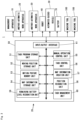
- the control device 50 is composed of a task program storage unit 51, a moving position storage unit 52, a motion posture storage unit 53, a map information storage unit 54, a manual operation control unit 55, a task control unit 56, a map information creation unit 57, a position recognition unit 58, a remaining battery power level recognition unit 59, a task management unit 60, and an input/output interface 61, and the like.
- the control device 50 is connected via this input/output interface 61 to the automated guided vehicle 30, the robot 40, and the battery 70 that constitute its own automated work apparatus 20, as well as via the network 15 described above to the management device 10, each machine tool 100, and other automated work apparatuses 20.
- the control device 50 is composed of a computer including a CPU, a RAM, and a ROM, and the manual operation control unit 55, task control unit 56, map information creation unit 57, position recognition unit 58, remaining battery power level recognition unit 59, task management unit 60, and input/output interface 61 are implemented by computer programs stored in a suitable recording medium of the control device 50 and execute the processes described below.
- the task program storage unit 51, the moving position storage unit 52, the motion posture storage unit 53, and the map information storage unit 54 are composed of a RAM or other suitable recording media.
- the manual operation control unit 55 is a functional unit that operates the automated guided vehicle 30 and the robot 40 according to operation signals inputted by an operator from a not-illustrated operation panel. That is, the operator can manually operate the automated guided vehicle 30 and the robot 40 (including the hand device 45 and the camera device 46) using an operation panel (not illustrated) under the control of this manual operation control unit 55.
- the task program storage unit 51 is a functional unit that stores programs for automated operation to automatedly operate the automated guided vehicles 30 and the robot 40 during automated operation, as well as programs for map creation to operate the automated guided vehicle 30 when creating map information in the factory, as described below.
- the program for automated operation and the program for map creation are, for example, inputted from the management device 10 connected via the network 15, or from the input/output unit disposed on the operation panel (not illustrated), and stored in the task program storage unit 51.
- the program for automated operation includes command codes for the moving position as the target position to which the automated guided vehicle 30 moves, moving speed, and orientation of the automated guided vehicle 30, command codes for the operation in which the robot 40 operates sequentially, and command codes for the operation of the hand device 45 and the operation of the camera device 46.
- the program for map creation includes a command code to have the automated guided vehicles 30 travel trackless everywhere in the factory so that the map information can be created by the map information creation unit 57.
- the map information storage unit 54 is a functional unit that stores map information including the layout information of machines, apparatuses, devices, and the like (devices and the like) located in the factory where the automated guided vehicle 30 travels, and this map information is created by the map information creation unit 57.
- the map information creation unit 57 acquires spatial information in the factory from the distance data detected by the sensors when the automated guided vehicles 30 is driven according to the map creation program stored in the task program storage unit 51 under the control of the task control unit 56 of the control device 50, and recognizes the planar shape of devices or the like to be installed in the factory, for example, recognizes the position, planar shape, and the like (arrangement information) of a specific device installed in the factory (in this example, each machine tool 100) based on the planar shape of the devices or the like registered in advance. Then, the map information creation unit 57 stores the obtained spatial information and arrangement information of devices and the like in the map information storage unit 54 as map information in the factory.
- the position recognition unit 58 is a functional unit that recognizes the position and posture of the automated guided vehicles 30 in the factory based on the distance data detected by the sensors and the map information in the factory, which is stored in the map information storage unit 54, and the operation of the automated guided vehicles 30 is controlled by the task control unit 56 based on the position and posture of the automated guided vehicles 30 recognized by this position recognition unit 58.
- the moving position storage unit 52 is a functional unit that stores a specific movement position as a specific target position to which the automated guided vehicle 30 moves, corresponding to the command code in the program, where the movement position includes each work position set for each machine tool 100 described above.
- This moving position is set, for example, by manually operating the automated guided vehicles 30 using the operation panel (not illustrated) under the control of the manual operation control unit 75 to move the automated guided vehicles 30 to each target position, and then storing the position data recognized by the position recognition unit 58 in the moving position storage unit 52. This operation is called a teaching operation.
- the motion posture storage unit 53 is a functional unit that stores data pertaining to the postures (motion postures) of the robot 40 that change sequentially as the robot 40 moves in a predetermined sequence and that corresponds to the command codes in the program.
- This data pertaining to the motion posture is the rotation angle data of each joint (motor) of the robot 40 in each posture when the robot 40 is manually operated to take each target posture by teaching operation using the operation panel (not illustrated) under the control by the manual operation control unit 55.
- This rotation angle data is stored in the motion posture storage unit 53 as data pertaining to the motion posture.
- the specific motion posture of the robot 40 is set at each machine tool 100, the material stocker 102, the product stocker 103, the material stocker 104, the product stockers 105 and 107, and the washing device 106, respectively.
- the posture pertaining to the attaching and detaching operations of the material W1 and the product W2 to and from the machine tool 100 specifically, the posture pertaining to each operation of removing the machined product W2 from the machine tool 100 and storing the product W2 in the product stocker 103, then taking out the material W1 in the material stocker 102 and attaching the material W1 onto the machine tool 100 is set.
- the posture pertaining to each operation of taking out the material W1 from the material stocker 104 and storing the material W1 in a first pallet 34 is set.
- the posture pertaining to each operation of taking out the product W2 stored in a second pallet 35 and storing the product W2 in the product stocker 105 is set.
- the posture pertaining to each operation of taking out the material W1 stored in the first pallet 34 and storing the material W1 in the material stocker 102 is set.
- the posture pertaining to each operation of taking out the product W2 stored in the product stocker 103 and storing the product W2 in the second pallet 35 is set.
- the posture pertaining to each operation of taking out the product W2 from the product stocker 105 and storing the product W2 in the first pallet 34 and each operation of taking out the product W2 stored in the first pallet 34 and storing the product W2 in the washing device 106 is set.
- the posture pertaining to each operation of taking out the product W2 from the washing device 106 and storing the product W2 on the second pallet 35, and each operation of taking out the product W2 stored on the second pallet 35 and storing the product W2 in the product stocker 107 is set.
- the task control unit 56 is a functional unit that uses any of the automated operation program and map creation program stored in the task program storage unit 51 and operates the automated guided vehicles 30 and robot 40 according to the programs. In doing so, the data stored in the moving position storage unit 52 and motion posture storage unit 53 described above are used as necessary.
- the task management unit 60 is a functional unit that receives task instructions from the management device 10 and has the task control unit 56 execute the received task, and the task control unit 56 reads out the program corresponding to the task from the task program storage unit 51 and executes the program in accordance with the task instructions from the task management unit 60.
- the remaining battery power level recognition unit 59 is a functional unit that recognizes the remaining power level of the battery 70 from the battery 70 via the input/output interface 61, and executes the process of sending information pertaining to the recognized remaining battery power level to the management device 10 via the input/output interface 61 at predetermined time intervals.
- the management device 10 is composed of a computer including a CPU, a RAM, a ROM, and the like, and is connected to each of the machine tools 100 and the automated work apparatus 20 via network 15, and has the function of managing the operational status thereof according to a predetermined machining schedule. For example, a task instruction process is executed to instruct each machine tool 100 and the automated work apparatus 20 to work, respectively, according to a predetermined machining schedule.
- the predetermined machine tool 100 is commanded to machine the predetermined workpiece W, and the predetermined automated work apparatus 20 is commanded to execute the attaching and detaching task that executes the detachment of the machined product W2 and the attachment of new material W1 from and to the corresponding machine tool 100, and the machining on each machine tool 100 is managed.
Landscapes
- Engineering & Computer Science (AREA)
- Mechanical Engineering (AREA)
- Robotics (AREA)
- General Physics & Mathematics (AREA)
- Physics & Mathematics (AREA)
- Quality & Reliability (AREA)
- Automation & Control Theory (AREA)
- Business, Economics & Management (AREA)
- Manufacturing & Machinery (AREA)
- Economics (AREA)
- General Engineering & Computer Science (AREA)
- Transportation (AREA)
- Power Engineering (AREA)
- Theoretical Computer Science (AREA)
- Human Resources & Organizations (AREA)
- Strategic Management (AREA)
- Tourism & Hospitality (AREA)
- General Business, Economics & Management (AREA)
- Operations Research (AREA)
- Radar, Positioning & Navigation (AREA)
- Aviation & Aerospace Engineering (AREA)
- Marketing (AREA)
- Remote Sensing (AREA)
- Life Sciences & Earth Sciences (AREA)
- Sustainable Development (AREA)
- Sustainable Energy (AREA)
- Entrepreneurship & Innovation (AREA)
- Development Economics (AREA)
- General Factory Administration (AREA)
- Control Of Position, Course, Altitude, Or Attitude Of Moving Bodies (AREA)
- Manipulator (AREA)
Abstract
Description
- This invention relates to a production system including a plurality of automated work apparatuses that execute a task on at least one production apparatus, the automated work apparatuses including a robot that executes a task on the production apparatus, an automated guided vehicle that has the robot mounted thereon and moves to a work position set to the production apparatus, a control device that controls the automated guided vehicle and the robot, and a battery that supplies electric power, as well as a method for managing a production system, and a program recording medium having a program for a production system management device recorded thereon.
- Conventionally, production systems called flexible manufacturing system (FMS) have been known. In this production system, for example, a plurality of machine tools are appropriately installed in a factory, and automated guided vehicles are used to transport workpieces and tools before machining to each machine tool. In addition, these automated guided vehicles are used to collect workpieces machined at each machine tool and used tools. Such a production system then allows for unmanned, automated production.
- As the automated guided vehicles mentioned above, an automated guided vehicle disclosed in
JP 2019-8359 A - According to this automated guided vehicle, first, for example, when the automated guided vehicle is operated by manual operation to travel inside a factory building, planar map information defining the inside contour of the factory building and the external outline of the machine tools and other apparatuses placed inside the building is created by the map creation unit based on the distance measurement data measured by the distance measurement device.
- An automated guided vehicle identifies its own current position (self-position) in the building based on the distance measurement data measured by the distance measurement device and the map information created in advance by the map creation unit. The automated guided vehicle then travels trackless and autonomously along a predetermined route based on the map information and self-position information in the building and transports the workpieces, tools, and the like as described above.
- In recent years, a production system with a robot mounted on the automated guided vehicle mentioned above has been proposed, as disclosed in
JP 2017-132002 A - In such a production system, a single robot, which is moved by an automated guided vehicle, can execute a task such as attaching and detaching workpieces to and from a plurality of machine tools, which allows more freedom in the layout of the machine tools than when the robots are installed to the machine tools in the fixed state. Therefore, the layout of the machine tools can be set up in a way that can achieve higher production efficiency. In addition, compared to conventional production systems with robots installed in a fixed state, a single robot can execute a task on a larger number of machine tools, thus saving equipment costs.
-
- [Patent Literature 1]
JP 2019-8359 A - [Patent Literature 2]
JP 2017-132002 A - By the way, the automated work apparatus composed of the automated guided vehicle, robot, and control device described above is supplied with electric power from a battery mounted on the automated guided vehicle, and this electric power allows the automated guided vehicle, robot, and control device to operate.
- The battery is then charged by receiving power from a power feeder when the automated work apparatus moves to the power feeder that is appropriately disposed. For this reason, when a task is being executed on the scheduled production apparatus and the remaining battery power level reaches the predetermined standard remaining power level, the battery has been conventionally charged from the power feeder while having the automated work apparatus move to the power feeder.
- However, the operation of the production equipment can be stopped if a battery, the remaining battery power level of which reaches the predetermined standard remaining power level, is charged while suspending the task being executed on the corresponding production apparatus. In such a case, the production efficiency (operation rate) of the production equipment will problematically be reduced.
- The present invention has been completed in view of the above state and has an object to provide a production system provided with an automated work apparatus that executes a task on a production apparatus, which can increase the operation rate of the production apparatus compared to conventional ones, or other means.
- In order to solve the above problem, the present invention relates to
- a production system including: a plurality of automated work apparatuses that execute a task on at least one production apparatus; and a management device that issues a task instruction to the automated work apparatuses and manages the task of the automated work apparatuses,
- the automated work apparatuses including a robot that executes a task on the production apparatus; an automated guided vehicle that has the robot mounted thereon and moves to a work position set to the production apparatus; a control device that controls the automated guided vehicle and the robot, and a battery that supplies electric power,
- the management device being configured to monitor a remaining battery power level of each automated work apparatus, compare a recognized remaining battery power level with a standard remaining power level required to complete an instructed task to check whether the instructed task can be completed, and if an automated work apparatus with an insufficient remaining battery power level that is below the standard remaining power level and is determined to be unable to complete the instructed task exists, search for the automated work apparatus with a sufficient remaining battery power level that exceeds the standard remaining power level and is able to complete the instructed task, and if an automated work apparatus with a sufficient remaining power level exists, instruct a task content instructed to the automated work apparatus with an insufficient remaining power level to the automated work apparatus with a sufficient remaining power level to take over the instructed task to the automated work apparatus with a sufficient remaining power level.
- According to this aspect (the first aspect) of the production system, the automated work apparatus operates under the management of the management device, and the automated work apparatus executes (provides) the predetermined task to the predetermined production apparatus.
- Then, the management device monitors the remaining battery power level of each automated work apparatus, compares the recognized remaining battery power level with the standard remaining power level required to complete an instructed task to check whether the instructed task can be completed, and if an automated work apparatus with an insufficient remaining battery power level that is below the standard remaining power level and is determined to be unable to complete the instructed task exists, searches for the automated work apparatus with a sufficient remaining battery power level that exceeds the standard remaining power level and is able to complete the instructed task, and if an automated work apparatus with a sufficient remaining power level that is able to complete the task exists, instructs the task contents instructed to the automated work apparatus with an insufficient remaining power level to the automated work apparatus with a sufficient remaining power level to have the automated work apparatus with a sufficient remaining power level take over the instructed task.
- Thus, according to this production system of the first aspect, if an automated work apparatus that is not able to complete the task exists, and another automated work apparatus that is able to complete the instructed task exists, the other automated work apparatus is caused to take over the task. Thus, the production apparatus to be provided with the work can be operated without stopping, thereby increasing the production efficiency (operating rate) of the production apparatus compared to conventional ones.
- In the production system of the first aspect, an aspect (a second aspect) in which if the automated work apparatus with a sufficient remaining power level does not exist, the management device is configured to instruct the automated work apparatus with an insufficient remaining power level to move to a charging station to have the automated work apparatus with an insufficient remaining power level move to the charging station may be adopted.
- In the production system of the first aspect, an aspect (a third aspect) in which if the automated work apparatus with a sufficient remaining power level exists, the management device is configured to have the automated work apparatus with a sufficient remaining power level take over a task and instruct the automated work apparatus with an insufficient remaining power level to move to a charging station to have the automated work apparatus with an insufficient remaining power level move to the charging station may be adopted.
- In the production system of the first aspect, an aspect (a fourth aspect) in which if an automated work apparatus with a sufficient remaining power level exists, the management device is configured to check whether the automated work apparatus with an insufficient remaining power level is able to complete a task instructed to the automated work apparatus with a sufficient remaining power level, and if it is determined that the task can be completed, exchange the task of the automated work apparatus with an insufficient remaining power level with the task of the automated work apparatus with a sufficient remaining power level, have the automated work apparatus with an insufficient remaining power level execute the task of the automated work apparatus with a sufficient remaining power level, and have the automated work apparatus with a sufficient remaining power level execute the task of the automated work apparatus with an insufficient remaining power level may be adopted. According to this fourth aspect, the utilization rate of an automated work apparatus can be increased in addition to the utilization rate of a production apparatus.
- Furthermore, the present invention is a production system including a plurality of automated work apparatuses that execute a task on at least one production apparatus,
- the automated work apparatuses including a robot that executes a task on the production apparatus, an automated guided vehicle that has the robot mounted thereon and moves to a work position set to the production apparatus, a control device that controls the automated guided vehicle and the robot, and a battery that supplies electric power,
- a control device of each automated work apparatus being configured to monitor its own remaining power level, compare the recognized remaining power level with the standard remaining power level required to complete the scheduled task to check whether the scheduled task can be completed, and if it is determined that the scheduled task cannot be completed, search for another automated work apparatus with a remaining battery power level that exceeds the standard remaining power level and is able to complete the task by mutual communication, and if another automated work apparatus with a remaining battery power level that is able to complete the task, have the other automated work apparatus takes over its own task of the automated work apparatus.
- According to the production system of this aspect (a fifth aspect), each automated work apparatus executes (provides) a predetermined task in response to a request from, for example, each production apparatus.
- Then, a control device of each automated work apparatus monitors its own remaining battery power level, compares the recognized remaining power level with the standard remaining power level required to complete a scheduled task to check whether the scheduled task can be completed, and if the remaining battery power level is below the standard remaining power level and is determined to be unable to complete the scheduled task, searches for another automated work apparatus with a remaining power level that exceeds the standard remaining power level and is able to complete the task by mutual communication, and if another automated work apparatus with a remaining power level that is able to complete the task, for example, sends information relating to its own task to the other automated work apparatus to have the other automated work apparatus take over the task.
- Thus, according to this production system of the fifth aspect, if an automated work apparatus that is unable to complete the task exists, and another automated work apparatus that is able to complete the task exists, the other automated work apparatus is caused to take over the task. Thus, the production apparatus to be provided with the work can be operated without stopping, thereby increasing the production efficiency (operating rate) of the production apparatus compared to conventional ones.
- In the production system of the fifth aspect, an aspect (a sixth aspect) in which if the other automated work apparatus does not exist, the control device of each automated work apparatus is configured to move to a charging station to charge the battery may be adopted.
- In the production system of the fifth aspect, an aspect (a seventh aspect) in which if the other automated work apparatus exists, the control device of each automated work apparatus is configured to take over its own task to the other automated work apparatus and move to a charging station to charge the battery may be adopted.
- In the production system of the fifth aspect, an aspect (an eighth aspect) in which if the other automated work apparatus exists, the control device of each automated work apparatus is configured to check whether a task instructed to the other automated work apparatus can be completed by itself, and if it is determined that a task can be completed, exchange its own task with the task of the other automated work apparatus and have the other automated work apparatus execute its own task and the task of the other automated work apparatus by itself may be adopted. According to this eighth aspect, the utilization rate of an automated work apparatus can be increased in addition to the utilization rate of a production apparatus.
- Furthermore, the present invention relates to a method for managing the task of an automated work apparatus by issuing a task instruction to the automated work apparatus in a production system that includes a plurality of automated work apparatuses executing a task on at least one production apparatus, the automated work apparatuses including a robot that executes a task on the production apparatus, an automated guided vehicle that has the robot mounted thereon and moves to a work position set to the production apparatus, a control device that controls the automated guided vehicle and robot, and a battery that supplies electric power, the method including:
- monitoring the remaining battery power level of each automated work apparatus;
- comparing the recognized remaining battery power level with the standard remaining power level required to complete an instructed task to check whether the instructed task can be completed;
- if an automated work apparatus with an insufficient remaining power level that is below the standard remaining power level and is determined to be unable to complete the instructed task, searching for an automated work apparatus with a sufficient remaining battery power level that exceeds the standard remaining power level and is able to complete the instructed task; and
- if an automated work apparatus with a sufficient remaining power level exists, instructing a task content instructed to an automated work apparatus with an insufficient remaining power level to an automated work apparatus with a sufficient remaining power level to have the automated work apparatus with an insufficient remaining power level take over the instructed task.
- In addition, the present invention relates to a program recording medium having a management device program used for a production system management device recorded thereon, the production system including: a plurality of automated work apparatuses that execute a task on at least one production apparatus; and a management device that issues a task instruction to the automated work apparatuses and manages a task of the automated work apparatuses, the automated work apparatuses including a robot that executes a task on the production apparatus, an automated guided vehicle that has the robot mounted thereon and moves to a work position set to the production apparatus, a control device that controls the automated guided vehicle and the robot, and a battery that supplies electric power,
the management device program being configured to execute: - a process of monitoring the remaining battery power level of each automated work apparatus;
- a process of comparing the recognized remaining battery power level with the standard remaining power level required to complete the instructed task to check whether the instructed task can be completed;
- if an automated work apparatus with an insufficient remaining battery power level that is below the standard remaining power level and is determined to be unable to complete the instructed task, a process of searching for an automated work apparatus with a sufficient remaining battery power level that exceeds the standard remaining power level and is able to complete the instructed task; and
- if an automated work apparatus with a sufficient remaining power level exists, a process of instructing an automated work apparatus with a sufficient remaining power level to take over the task content instructed to an automated work apparatus with an insufficient remaining power level to have the automated work apparatus with a sufficient remaining battery take over the instructed task.
- As stated above, according to the production system of the present invention, if an automated work apparatus (a first automated work apparatus) that is not able to complete the task exists, and another automated work apparatus (a second automated work apparatus) that is able to complete the task exists, the other automated work apparatus is caused to take over the task. Thus, the production apparatus to be provided with the work can be operated without stopping, thereby increasing the production efficiency (operating rate) of the production apparatus compared to conventional ones.
-
- [
Fig. 1 ]
Fig. 1 is a schematic diagram illustrating the schematic framework of a production system according to one embodiment of the present invention. - [
Fig. 2 ]
Fig. 2 is a plan view illustrating the device configuration of the production system according to the present embodiment. - [
Fig. 3 ]
Fig. 3 is a block diagram illustrating an outline of the control device that constitutes the automated work apparatus according to the present embodiment. - [
Fig. 4 ]
Fig. 4 is a plan view illustrating the automated work apparatus according to the present embodiment. - [
Fig. 5 ]
Fig. 5 is a right-side view of the automated work apparatus illustrated inFig. 4 . - [
Fig. 6 ]
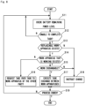
Fig. 6 is a flowchart illustrating the process in the management device according to the present embodiment. - [
Fig. 7 ]
Fig. 7 is a block diagram illustrating an outline of the control device that constitutes the automated work apparatus according to another embodiment of the present invention. - [
Fig. 8 ]
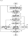
Fig. 8 is a flowchart illustrating the process in the task management unit of the control device according to another present embodiment. - Hereinafter, the production system according to a specific embodiment of the present invention will be described with reference to the drawings.
- As shown in
Figs. 1 and2 , theproduction system 1 of this example is composed of two machine tools 100 (100A and 100B) as production apparatuses; amaterial stocker 104 that stores a material W1 before machining; aproduct stocker 105 that stores a product W2 after machining; awashing device 106 that washes the product W2; aproduct stocker 107 that stores the product W2 after washing; four automated work apparatuses 20 (20A, 20B, 20C, and 20D) that execute a task on eachmachine tool 100, thematerial stocker 104, theproduct stocker 105, thewashing device 106, theproduct stocker 107, and the like; amanagement device 10 that manages the task of eachmachine tool 100 and anautomated work apparatus 20 by issuing task instructions to eachmachine tool 100 and theautomated work apparatus 20; and the like. Themanagement device 10, eachautomated work apparatus 20, and eachmachine tool 100 are interconnected via anetwork 15 such as the Internet. Needless to say, the device configuration illustrated inFig. 1 is exemplary and is not limited thereto. - The
machine tool 100 is applicable to all conventionally known machine tools with communication functions to connect tonetwork 15, such as NC lathes and machining centers. As shown inFig. 2 , in this example, twomachine tools machine tools 100 to be installed and the arrangement thereof are not limited thereto. - In the vicinity of each machine tool 100 (100A or 100B), power feeders 101 (101A and 101B), material stockers 102 (102 and 102B) to store the material W1, and product stockers 103 (103A and 103B) to store the product W2 are disposed respectively. The
material stocker 104 and theproduct stocker 105 are stockers with a larger capacity than thematerial stockers 102 andproduct stockers 103, and are located a short distance away from themachine tools 100. Apower feeder 108 is also provided in the vicinity of thematerial stocker 104. - As shown in
Figs. 4 and5 , theautomated work apparatus 20 is composed of an automated guidedvehicle 30, arobot 40 mounted on the automated guidedvehicle 30, acontrol device 50 that controls the automated guidedvehicle 30 and therobot 40, and abattery 70 that supplies power to the automated guidedvehicle 30, therobot 40, and thecontrol device 50. - The automated guided
vehicle 30 has therobot 40 mounted on the top surface thereof (the loading surface 31), and afirst pallet 34 and asecond pallet 35 are further placed side by side on theloading surface 31. The first andsecond pallets automated work apparatus 20. - The automated guided
vehicles 30 is provided with a sensor capable of recognizing its own position in the factory (for example, a distance-measuring sensor using a laser beam) and is configured to travel trackless in the factory, including the area where themachine tool 100 is located, under the control of thecontrol device 50. In this example, the automated guidedvehicle 30 moves to work positions respectively set for eachmachine tool 100, thematerial stocker 104, theproduct stockers washing device 106, and to the power receiving position set for thepower feeder 108. In this example, thecontrol device 50 and thebattery 70 are located in this automated guidedvehicle 30. - The
robot 40 is an articulated robot with three arms (afirst arm 41, asecond arm 42, and a third arm 43), which are manipulator units, connected by joints so that thesefirst arm 41,second arm 42, andthird arm 43 are jointed together, and asupport shaft 44a is attached to the distal end of thethird arm 43, and ahand device 45 as an end-effector is attached to thissupport shaft 44a. Furthermore, asupport bar 44b is attached to thesupport shaft 44a, and acamera device 46, also as an end effector, is attached to thissupport bar 44b. Therobot 40 then moves thesehand device 45 andcamera device 46 in three-dimensional space under the control of thecontrol device 50. The structure of therobot 40 is not limited to such an articulated type but may adopt any known available structure. - As shown in
Fig. 3 , thecontrol device 50 is composed of a taskprogram storage unit 51, a movingposition storage unit 52, a motionposture storage unit 53, a mapinformation storage unit 54, a manualoperation control unit 55, atask control unit 56, a mapinformation creation unit 57, aposition recognition unit 58, a remaining battery powerlevel recognition unit 59, atask management unit 60, and an input/output interface 61, and the like. Thecontrol device 50 is connected via this input/output interface 61 to the automated guidedvehicle 30, therobot 40, and thebattery 70 that constitute its ownautomated work apparatus 20, as well as via thenetwork 15 described above to themanagement device 10, eachmachine tool 100, and other automated work apparatuses 20. - The
control device 50 is composed of a computer including a CPU, a RAM, and a ROM, and the manualoperation control unit 55,task control unit 56, mapinformation creation unit 57,position recognition unit 58, remaining battery powerlevel recognition unit 59,task management unit 60, and input/output interface 61 are implemented by computer programs stored in a suitable recording medium of thecontrol device 50 and execute the processes described below. The taskprogram storage unit 51, the movingposition storage unit 52, the motionposture storage unit 53, and the mapinformation storage unit 54 are composed of a RAM or other suitable recording media. - The manual
operation control unit 55 is a functional unit that operates the automated guidedvehicle 30 and therobot 40 according to operation signals inputted by an operator from a not-illustrated operation panel. That is, the operator can manually operate the automated guidedvehicle 30 and the robot 40 (including thehand device 45 and the camera device 46) using an operation panel (not illustrated) under the control of this manualoperation control unit 55. - The task
program storage unit 51 is a functional unit that stores programs for automated operation to automatedly operate the automated guidedvehicles 30 and therobot 40 during automated operation, as well as programs for map creation to operate the automated guidedvehicle 30 when creating map information in the factory, as described below. The program for automated operation and the program for map creation are, for example, inputted from themanagement device 10 connected via thenetwork 15, or from the input/output unit disposed on the operation panel (not illustrated), and stored in the taskprogram storage unit 51. - The program for automated operation includes command codes for the moving position as the target position to which the automated guided
vehicle 30 moves, moving speed, and orientation of the automated guidedvehicle 30, command codes for the operation in which therobot 40 operates sequentially, and command codes for the operation of thehand device 45 and the operation of thecamera device 46. The program for map creation includes a command code to have the automated guidedvehicles 30 travel trackless everywhere in the factory so that the map information can be created by the mapinformation creation unit 57. - The map
information storage unit 54 is a functional unit that stores map information including the layout information of machines, apparatuses, devices, and the like (devices and the like) located in the factory where the automated guidedvehicle 30 travels, and this map information is created by the mapinformation creation unit 57. - The map
information creation unit 57 acquires spatial information in the factory from the distance data detected by the sensors when the automated guidedvehicles 30 is driven according to the map creation program stored in the taskprogram storage unit 51 under the control of thetask control unit 56 of thecontrol device 50, and recognizes the planar shape of devices or the like to be installed in the factory, for example, recognizes the position, planar shape, and the like (arrangement information) of a specific device installed in the factory (in this example, each machine tool 100) based on the planar shape of the devices or the like registered in advance. Then, the mapinformation creation unit 57 stores the obtained spatial information and arrangement information of devices and the like in the mapinformation storage unit 54 as map information in the factory. - The
position recognition unit 58 is a functional unit that recognizes the position and posture of the automated guidedvehicles 30 in the factory based on the distance data detected by the sensors and the map information in the factory, which is stored in the mapinformation storage unit 54, and the operation of the automated guidedvehicles 30 is controlled by thetask control unit 56 based on the position and posture of the automated guidedvehicles 30 recognized by thisposition recognition unit 58. - The moving
position storage unit 52 is a functional unit that stores a specific movement position as a specific target position to which the automated guidedvehicle 30 moves, corresponding to the command code in the program, where the movement position includes each work position set for eachmachine tool 100 described above. This moving position is set, for example, by manually operating the automated guidedvehicles 30 using the operation panel (not illustrated) under the control of the manual operation control unit 75 to move the automated guidedvehicles 30 to each target position, and then storing the position data recognized by theposition recognition unit 58 in the movingposition storage unit 52. This operation is called a teaching operation. - The motion
posture storage unit 53 is a functional unit that stores data pertaining to the postures (motion postures) of therobot 40 that change sequentially as therobot 40 moves in a predetermined sequence and that corresponds to the command codes in the program. This data pertaining to the motion posture is the rotation angle data of each joint (motor) of therobot 40 in each posture when therobot 40 is manually operated to take each target posture by teaching operation using the operation panel (not illustrated) under the control by the manualoperation control unit 55. This rotation angle data is stored in the motionposture storage unit 53 as data pertaining to the motion posture. - The specific motion posture of the
robot 40 is set at eachmachine tool 100, thematerial stocker 102, theproduct stocker 103, thematerial stocker 104, theproduct stockers washing device 106, respectively. For example, in the work on themachine tool 100, the posture pertaining to the attaching and detaching operations of the material W1 and the product W2 to and from themachine tool 100, specifically, the posture pertaining to each operation of removing the machined product W2 from themachine tool 100 and storing the product W2 in theproduct stocker 103, then taking out the material W1 in thematerial stocker 102 and attaching the material W1 onto themachine tool 100 is set. - In the task of taking out material W1 from the
material stocker 104, the posture pertaining to each operation of taking out the material W1 from thematerial stocker 104 and storing the material W1 in afirst pallet 34 is set. In the task of storing the product W2 inproduct stocker 105, the posture pertaining to each operation of taking out the product W2 stored in asecond pallet 35 and storing the product W2 in theproduct stocker 105 is set. - In the task of supplying the material W1 to each
material stocker 102, the posture pertaining to each operation of taking out the material W1 stored in thefirst pallet 34 and storing the material W1 in thematerial stocker 102 is set. In the task of taking out the product W2 from eachproduct stocker 103, the posture pertaining to each operation of taking out the product W2 stored in theproduct stocker 103 and storing the product W2 in thesecond pallet 35 is set. - In the task of taking out the product W2 from the
product stocker 105 and storing the product W2 in thewashing device 106, the posture pertaining to each operation of taking out the product W2 from theproduct stocker 105 and storing the product W2 in thefirst pallet 34 and each operation of taking out the product W2 stored in thefirst pallet 34 and storing the product W2 in thewashing device 106 is set. - In the task of taking out the product W2 after washing from the
washing device 106 and storing the product W2 in theproduct stocker 107, the posture pertaining to each operation of taking out the product W2 from thewashing device 106 and storing the product W2 on thesecond pallet 35, and each operation of taking out the product W2 stored on thesecond pallet 35 and storing the product W2 in theproduct stocker 107 is set. - The
task control unit 56 is a functional unit that uses any of the automated operation program and map creation program stored in the taskprogram storage unit 51 and operates the automated guidedvehicles 30 androbot 40 according to the programs. In doing so, the data stored in the movingposition storage unit 52 and motionposture storage unit 53 described above are used as necessary. - The
task management unit 60 is a functional unit that receives task instructions from themanagement device 10 and has thetask control unit 56 execute the received task, and thetask control unit 56 reads out the program corresponding to the task from the taskprogram storage unit 51 and executes the program in accordance with the task instructions from thetask management unit 60. - The remaining battery power
level recognition unit 59 is a functional unit that recognizes the remaining power level of thebattery 70 from thebattery 70 via the input/output interface 61, and executes the process of sending information pertaining to the recognized remaining battery power level to themanagement device 10 via the input/output interface 61 at predetermined time intervals. - The
management device 10 is composed of a computer including a CPU, a RAM, a ROM, and the like, and is connected to each of themachine tools 100 and theautomated work apparatus 20 vianetwork 15, and has the function of managing the operational status thereof according to a predetermined machining schedule. For example, a task instruction process is executed to instruct eachmachine tool 100 and theautomated work apparatus 20 to work, respectively, according to a predetermined machining schedule. Specifically, in accordance with the machining schedule, thepredetermined machine tool 100 is commanded to machine the predetermined workpiece W, and the predeterminedautomated work apparatus 20 is commanded to execute the attaching and detaching task that executes the detachment of the machined product W2 and the attachment of new material W1 from and to thecorresponding machine tool 100, and the machining on eachmachine tool 100 is managed. - The management functions in the management device 10 (functions including the processes illustrated in
Fig. 6 , which will be described below) are implemented by themanagement device 10 executing the computer program (management device program) stored in a suitable recording medium of themanagement device 10. Also, in another mode, the management device program can be recorded on a conventionally known external program recording medium, such as a portable USB memory or a CD-ROM, and themanagement device 10 can execute the management device program stored in this program recording medium, or after reading the management device program from the program recording medium, the management device program can be executed. The management device program can also be stored (downloaded) in themanagement device 10 via a suitable network, such as thenetwork 15 described above. - The attaching and detaching task corresponds to the task of taking out the machined product W2 in the
machine tool 100 and storing the product W2 in theproduct stocker 103, and then taking out the material W1 in thematerial stocker 102 and supplying the material W1 to themachine tool 100. In this example, when this attaching and detaching task is executed, theautomated work apparatus 20 is always positioned in the working position of thecorresponding machine tool 100 to execute the attaching and detaching task, and during this attaching and detaching task, thebattery 70 is charged by the power supply from thepower feeder 101. - In addition, the
management device 10 commands the predeterminedautomated work apparatus 20 to execute a material supply task to take out the material W1 stored in thematerial stocker 104 from thematerial stocker 104 and supply the material W1 to thematerial stocker 102 of eachmachine tool 100 and a product collection task to take out the product W2 stored in theproduct stocker 103 of eachmachine tool 100 and collect the product W2 in theproduct stocker 105. In this material supply task and product collection task, theautomated work apparatus 20 moves between thematerial stocker 102 andproduct stocker 103 attached to eachmachine tool 100 and thematerial stocker 104 andproduct stocker 105. - In addition, the
management device 10 commands the predeterminedautomated work apparatus 20 to take out the products stored in theproduct stocker 105 and supply the products to thewashing device 106 according to the machining schedule, and to wash the products W2 washed by thewashing device 106 and store the products W2 in theproduct stocker 107. When executing this washing task, theautomated work apparatus 20 executes the task while moving between theproduct stocker 105, thewashing device 106, and theproduct stocker 107. - In the example illustrated in
Fig. 2 , theautomated work apparatus 20A executes the task of supplying the material W1 to themachine tool 100A and the task of taking out the product W2 after machining, and theautomated work apparatus 20B executes the task of supplying material W1 to themachine tool 100B and the task of taking out the product W2 after machining. Theautomated work apparatus 20C executes the task of supplying the material W1 and the task of collecting the product W2 between thematerial stocker product stocker machine tool material stockers 104 and theproduct stockers 105. Theautomated work apparatus 20C also executes the washing work between theproduct stocker 105, thewashing device 106, and theproduct stocker 107. Theautomated work apparatus power feeders respective batteries 70 during their respective tasks, and thebatteries 70 are maintained in a fully charged state. - The
management device 10 recognizes the remaining power level of thebattery 70 of eachautomated work apparatus 20 and executes a task coordination process to coordinate the task of eachautomated work apparatus 20 according to the remaining power level. Specifically, themanagement device 10 executes the process illustrated inFig. 6 . That is, themanagement device 10 monitors the remaining power level sent from the remaining battery powerlevel recognition unit 59 of each automated work apparatus 20 (step S1) and determines whether the task commanded to eachautomated work apparatus 20 can be completed with the remaining battery power level (step S2). For example, themanagement device 10 holds the remaining battery power level required for the instructed task in a table format in advance as a standard remaining power level, and determines that the task will not be completed when the remaining battery power level of theautomated work apparatus 20 falls below the standard remaining power level set for the instructed task. - When an
automated work apparatus 20 with a remaining battery power level that is below the standard remaining power level occurs, themanagement device 10 searches for the existence of anautomated work apparatus 20 with a remaining power level that exceeds this standard remaining power level (step S3), and if no applicableautomated work apparatus 20 exists, themanagement device 10 instructs theautomated work apparatus 20 to move to thepower feeder 108 to charge thebattery 70 with an insufficient remaining power level (step S8). - If an applicable
automated work apparatus 20 exists in step S3, themanagement device 10 determines whether or not theautomated work apparatus 20 is working (step S4), and if it is determined that theautomated work apparatus 20 is working, themanagement device 10 determines whether or not theautomated work apparatus 20 with an insufficient remaining power level is able to complete the task of theautomated work apparatus 20 to be exchanged (step S5). If themanagement device 10 determines that the task can be completed, themanagement device 10 instructs to exchange the previously instructed task between theautomated work apparatus 20 with a sufficient remaining power level and theautomated work apparatus 20 with an insufficient remaining power level (step S7). If themanagement device 10 determines that the task cannot be completed, themanagement device 10 instructs theautomated work apparatus 20 with an insufficient remaining power level to move to thepower feeder 108 to charge thebattery 70 with an insufficient remaining power level (step S8). - For example, in the example illustrated in
Fig. 2 , if theautomated work apparatus 20C that is executing the task of supplying material W1 and the task of collecting product W2 becomes insufficient in the remaining power level, andautomated work apparatuses automated work apparatuses 20 with a sufficient remaining power level, themanagement device 10 determines whether or not theseautomated work apparatuses management device 10 determines whether or not theautomated work apparatus 20C is able to take over these tasks. - If it is determined that the
automated work apparatus 20C is able to take over the task of any ofautomated work apparatus management device 10 instructs to exchange the previously instructed task between any of theautomated work apparatus automated work apparatus 20C. For example, ifautomated work apparatus 20C is able to take over the task ofautomated work apparatus 20D, themanagement device 10 can exchange tasks betweenautomated work apparatus 20C andautomated work apparatus 20D. - On the contrary, if it is determined that the
automated work apparatus 20C is unable to take over the task of any ofautomated work apparatus management device 10 instructs theautomated work apparatus 20C to move to thepower feeder 108 to charge thebattery 70 with an insufficient remaining power level. - If the
management device 10 determines in step S4 that the applicableautomated work apparatus 20 is not working and is on standby, theautomated work apparatus 20 with a sufficient remaining power level is made to take over the task of theautomated work apparatus 20 with an insufficient remaining power level, and themanagement device 10 instructs to theautomated work apparatus 20 with an insufficient remaining power level to move to thepower feeder 108 to charge thebattery 70 with an insufficient remaining power level (step S6). - Thereafter, the
management device 10 repeats the above steps S1 to S8 until it is ready to terminate the process (step S9) . - According to the
production system 1 with the above configuration in this example, machining in eachmachine tool 100 is managed under the management of themanagement device 10, and necessary machining is executed in eachmachine tool 100 according to the schedule provided in themanagement device 10. In addition, the task of supplying the material W1 before machining to eachmachine tool 100 and the task of taking out the product W2 after machining, as well as the task of supplying the material W1 and the task of collecting the product W2 executed between thematerial stocker 102 and theproduct stocker 103 attached to eachmachine tool 100 and thematerial stocker 104 and theproduct stocker 105, and the task of washing executed between theproduct stocker 105, thewashing device 106, and theproduct stocker 107 are executed by theautomated work apparatus 20 selected by themanagement device 10. - The
management device 10 then executes the task coordination process illustrated inFig. 6 while eachautomated work apparatus 20 is in operation. That is, themanagement device 10 monitors the remaining power level of thebattery 70 of eachautomated work apparatus 20, determines whether the task commanded to eachautomated work apparatus 20 can be completed with the recognized remaining battery power level, and if anautomated work apparatus 20 with an insufficient remaining power level that is unable to complete the task exists, theautomated work apparatus 20 with an insufficient remaining power level and the otherautomated work apparatus 20 with a sufficient remaining power level are exchanged between each other, if possible. - On the contrary, if no other
automated work apparatus 20 that is able to exchange the task exists and anotherautomated work apparatus 20 on standby that is able to take over the task exists, themanagement device 10 has the automatedwork apparatus 20 on standby take over the task and have thebattery 70 of theautomated work apparatus 20 with an insufficient remaining power level charged. Also, if no otherautomated work apparatus 20 that is able to take over the task exists, themanagement device 10 has thebattery 70 of theautomated work apparatus 20 with an insufficient remaining power level charged. - As stated above, according to the
production system 1 of the present example, if anautomated work apparatus 20 that is unable to complete the task exists and anotherautomated work apparatus 20 that is able to complete the task exists, the task is taken over by the other automated work apparatus. Thus, the production apparatus to be provided with the work can be operated without stopping, thereby increasing the production efficiency (operating rate) of the production apparatus compared to conventional ones. - For example, in the above example, when the battery level of the
automated work apparatus 20C that is executing the task of supplying the material W1 and the task of collecting the product W2 becomes insufficient and the task is then exchanged between theautomated work apparatus 20C and theautomated work apparatus 20D that is executing the cleaning task, theautomated work apparatus 20C leaves for charging, which prevents the delay in supplying the material W1 to thematerial stockers product stockers - If respective tasks of the
automated work apparatus 20 with an insufficient remaining battery power level and theautomated work apparatus 20 with a sufficient remaining power level are exchanged between each other, the time that theautomated work apparatus 20 leaves for charging can be kept as short as possible, and the utilization rate of theautomated work apparatus 20 can be increased. - Although one embodiment of the present invention has been described above, the mode in which the present invention can be adopted is not limited in any way to the above examples.
- For example, in the above example, the system is configured to have the
management device 10 coordinate the task according to the remaining power level of theautomated work apparatus 20, but is not limited to such a configuration. For example, such adjustment of works may be carried out autonomously in eachautomated work apparatus 20. - The production system 1' with such an automated control device 20' is illustrated in
Fig. 7 . This production system 1' differs from theproduction system 1 in the above example only in the process of themanagement device 1 and thecontrol device 50 of theautomated work apparatus 20, and is identical in other configurations. - Specifically, the configuration of the management device 1' in this example differs from that of the
management device 1 in the above example only in that the management device 1' does not execute the task coordination process illustrated inFig. 6 described above. The configuration of the control device 50' differs from that of thecontrol device 50 in the above example only in that the task management unit 60' thereof is configured to additionally execute the task coordination process illustrated inFig. 8 , compared to thetask management unit 60 in the above example. Thus, in this example, task coordination according to the remaining battery power level is executed autonomously in each automated work apparatus 20'. - Specifically, the task management unit 60' in this example receives task instructions from the
management device 10 and, in addition to the process of having thetask control unit 56 execute the received task, executes the autonomous work coordination process illustrated inFig. 8 with the other automated work apparatus 20'. - That is, the task management unit 60' of each automated work apparatus 20' monitors the remaining power level of the
battery 70 recognized by the remaining battery power level recognition unit 59 (step S11) and determines whether the remaining battery power level is sufficient to complete the task commanded by the management device 10' (step S12). For example, the work management device 60' holds the remaining battery power level required for the instructed task in a table format in advance as a standard remaining power level, and determines that the task will not be completed when the remaining battery power level recognized by the remaining battery powerlevel recognition unit 59 falls below the standard remaining power level set for the instructed task. - When the remaining battery power level falls below the standard remaining power level, the work management device 60' communicates with the work management device 60' of another automated work apparatus 20' mutually to search for the existence of an automated work apparatus 20' with a remaining battery power level that exceeds this standard remaining battery level, and if no applicable automated work apparatus 20' exists (step S13), the work management device 60' sends a charging operation instruction to the
task control unit 56 to execute the process of moving the automated work apparatus 20' to thepower feeder 108 to charge the battery 70 (step S18). - On the other hand, if the existence of the applicable automated work apparatus 20' is confirmed in step S13, the task management unit 60' further determines, through intercommunication with the automated work apparatus 20', whether or not the target automated work apparatus 20' is working (step S14). If the task management unit 60' determines that the target automated work apparatus 20' is working, the task management unit 60' further determines whether or not the target automated work apparatus 20' is able to complete the task of the applicable automated work apparatus 20' by itself (step S15). If the task management unit 60' determines that the task can be completed, the task management unit 60' instructs its own
task control unit 56 to execute the process of mutually rotating respective tasks with the target automated work apparatus 20', for example, mutually sending information (task codes, etc.) related to the content of respective tasks, and then execute the task of the other party received (step S17). On the other hand, if it is determined that the task cannot be completed, the task management unit 60' sends a charging operation instruction to its owntask control unit 56 to execute a process to move the automated work apparatus 20' to thepower feeder 108 and charge the battery 70 (step S18). - If the work management device 60' determines in step S14 that the applicable automated work apparatus 20' is not working and is on standby, the work management device 60' has the target automated work apparatus 20' to take over its own task and sends a charging operation instruction to its own
task control unit 56 to execute the process of moving the automated work apparatus 20' to thepower feeder 108 to charge the battery 70 (step S16). - Thereafter, the task management unit 60' repeats the above steps S11 to S18 until it is ready to terminate the process (step S19).
- As stated above, also according to the production system 1' of this example, as with the
production system 1 of the example above, if an automated work apparatus 20' that is unable to complete the task exists and another automated work apparatus 20' that is able to complete the task exists, the task can be taken over by the other automated work apparatus 20'. Thus, the production apparatus to be provided with the work can be operated without stopping, thereby increasing the production efficiency (operating rate) of the production apparatus compared to conventional ones. - If respective tasks of the automated work apparatus 20' with an insufficient remaining battery power level and the automated work apparatus 20' with a sufficient remaining power level are exchanged between each other, the time that the automated work apparatus 20' leaves for charging can be kept as short as possible, and the operation rate of the automated work apparatus 20' can be increased.
- The work management computer program (computer program functioning as the task management unit 60') for executing the process illustrated in
Fig. 8 above can also be recorded on a portable external program recording medium, and the control device 50' of each automated work apparatus 20' can execute the work management computer program recorded on this program recording medium, or after reading the work management computer program from the program recording medium into the control device 50', the work management computer program can be executed. The work management computer program can be stored (downloaded) in the control device 50' via a network as appropriate. - Although it is stated again, the explanations of the above embodiments are in all respects illustrative and not restrictive. Variations and modifications are possible for a person skilled in the art as appropriate. The scope of the present invention is indicated by the claims, not by the embodiments described above. Furthermore, the scope of the present invention includes modifications from embodiments within the claims and the scope of equivalents.
-
- 1 Production System
- 10 Management device
- 20 (20A, 20B, 20C, 20D) Automated work apparatus
- 30 Automated guided vehicle
- 34 First pallet
- 35 Second pallet
- 40 Robot
- 50 Control device
- 70 Battery
- 100(100A, 100B) Machine tool
- 101(101A, 101B) Charging device
- 102 (102A, 102B) Material stocker
- 103 (103A, 103B) Product stocker
- 104 Material stocker
- 105 Product stocker
- 106 Washing device
- 107 Product stocker
- 108 Charging device
Claims (10)
- A production system comprising: a plurality of automated work apparatuses that execute a task on at least one production apparatus; and a management device that issues a task instruction to the automated work apparatuses and manages a task of the automated work apparatuses,the automated work apparatuses including a robot that executes a task on the production apparatus; an automated guided vehicle that has the robot mounted thereon and moves to a work position set to the production apparatus; a control device that controls the automated guided vehicle and the robot, and a battery that supplies electric power,the management device being configured to monitor a remaining battery power level of each automated work apparatus, compare a recognized remaining battery power level with a standard remaining power level required to complete an instructed task to check whether the instructed task can be completed, and if an automated work apparatus with an insufficient remaining battery power level that is below the standard remaining power level and is determined to be unable to complete the instructed task exists, search for the automated work apparatus with a sufficient remaining battery power level that exceeds the standard remaining power level and is able to complete the instructed task, and if an automated work apparatus with a sufficient remaining power level exists, instruct a task content instructed to the automated work apparatus with an insufficient remaining power level to the automated work apparatus with a sufficient remaining power level to have the automated work apparatus with a sufficient remaining power level take over the instructed task.
- The production system according to claim 1, wherein if the automated work apparatus with a sufficient remaining power level does not exist, the management device is configured to instruct the automated work apparatus with an insufficient remaining power level to move to a charging station to have the automated work apparatus with an insufficient remaining power level move to the charging station.
- The production system according to claim 1, wherein if the automated work apparatus with a sufficient remaining power level exists, the management device is configured to have the automated work apparatus with a sufficient remaining power level take over a task and instruct the automated work apparatus with an insufficient remaining power level to move to a charging station to have the automated work apparatus with an insufficient remaining power level move to the charging station.
- The production system according to claim 1, wherein, if an automated work apparatus with a sufficient remaining power level exists, the management device is configured to check whether the automated work apparatus with an insufficient remaining power level is able to complete a task instructed to the automated work apparatus with a sufficient remaining power level, and if it is determined that automated work apparatus with an insufficient remaining power level is able to complete the task, exchange a task of the automated work apparatus with an insufficient remaining power level with the task of the automated work apparatus with a sufficient remaining power level, have the automated work apparatus with an insufficient remaining power level execute the task of the automated work apparatus with a sufficient remaining power level, and have the automated work apparatus with a sufficient remaining power level execute the task of the automated work apparatus with an insufficient remaining power level.
- A production system comprising: a plurality of automated work apparatuses that execute a task on at least one production apparatus,the automated work apparatuses including a robot that executes a task on the production apparatus; an automated guided vehicle that has the robot mounted thereon and moves to a work position set to the production apparatus; a control device that controls the automated guided vehicle and the robot, and a battery that supplies electric power,a control device of each of the automated work apparatuses being configured to monitor its own remaining battery power level, compare a recognized remaining battery power level with a standard remaining power level required to complete a scheduled task to check whether the scheduled task can be completed, and if the remaining battery power level is below the standard remaining power level and is determined to be unable to complete the scheduled task, search for another automated work apparatus with a remaining battery power level that exceeds the standard remaining power level and is able to complete the task by mutual communication, and if another automated work apparatus with a remaining battery power level that is able to complete the task, have the other automated work apparatus take over its own task.
- The production system of claim 5, wherein if the other automated work apparatus does not exist, the control device of each automated work apparatus is configured to move to a charging station to charge the battery.
- The production system of claim 5, wherein if the other automated work apparatus exists, the control device of each automated work apparatus is configured to take over its own task to the other automated work apparatus and move to a charging station to charge the battery.
- The production system of claim 5, wherein if the other automated work apparatus exists, the control device of each automated work apparatus is configured to check whether a task instructed to the other automated work apparatus can be completed by itself, and if it is determined that the task can be completed, exchange its own task with a task of the other automated work apparatus and have the other automated work apparatus execute its own task and execute the task of the other automated work apparatus by itself.
- A production system management method for managing a task of an automated work apparatus by issuing a task instruction to the automated work apparatus in a production system provided that includes a plurality of automated work apparatuses executing a task on at least one production apparatus, the automated work apparatuses including a robot that executes a task on the production apparatus, an automated guided vehicle that has the robot mounted thereon and moves to a work position set to the production apparatus, a control device that controls the automated guided vehicle and the robot, and a battery that supplies electric power, the method comprising:monitoring a remaining battery power level of each automated work apparatus;comparing a recognized remaining battery power level with a standard remaining power level required to complete an instructed task to check whether the instructed task can be completed;if an automated work apparatus with an insufficient remaining battery power level that is below the standard remaining power level and is determined to be unable to complete the instructed task, searching for an automated work apparatus with a sufficient remaining battery power level that exceeds the standard remaining power level and is able to complete the instructed task; andif an automated work apparatus with a sufficient remaining power level exists, instructing a task content instructed to an automated work apparatus with an insufficient remaining power level to an automated work apparatus with a sufficient remaining power level to have the automated work apparatus with an insufficient remaining power level take over the instructed task.
- A program recording medium having a management device program used for a production system management device recorded thereon, the production system including: a plurality of automated work apparatuses that execute a task on at least one production apparatus; and a management device that issues a task instruction to the automated work apparatuses and manages a task of the automated work apparatuses, the automated work apparatuses including a robot that executes a task on the production apparatus; an automated guided vehicle that has the robot mounted thereon and moves to a work position set to the production apparatus; a control device that controls the automated guided vehicle and the robot, and a battery that supplies electric power,
the management device program being configured to execute:a process of monitoring a remaining battery power level of each automated work apparatus;a process of comparing a recognized remaining battery power level with a standard remaining power level required to complete an instructed task to check whether the instructed task can be completed;if an automated work apparatus with an insufficient remaining battery power level that is below the standard remaining power level and is determined to be unable to complete the instructed task, a process of searching for an automated work apparatus with a sufficient remaining battery power level that exceeds the standard remaining power level and is able to complete the instructed task; andif an automated work apparatus with a sufficient remaining power level exists, a process of instructing an automated work apparatus with a sufficient remaining power level to take over a task content instructed to an automated work apparatus with an insufficient remaining power level to have the automated work apparatus with a sufficient remaining battery take over the instructed task.
Applications Claiming Priority (2)
| Application Number | Priority Date | Filing Date | Title |
|---|---|---|---|
| JP2022078225A JP7494433B2 (en) | 2022-05-11 | 2022-05-11 | Production System |
| PCT/JP2023/016655 WO2023218987A1 (en) | 2022-05-11 | 2023-04-27 | Production system, production system management method, and program recording medium having program for production system management device recorded thereon |
Publications (2)
| Publication Number | Publication Date |
|---|---|
| EP4517459A1 true EP4517459A1 (en) | 2025-03-05 |
| EP4517459A4 EP4517459A4 (en) | 2026-03-11 |
Family
ID=88730386
Family Applications (1)
| Application Number | Title | Priority Date | Filing Date |
|---|---|---|---|
| EP23803466.4A Pending EP4517459A4 (en) | 2022-05-11 | 2023-04-27 | PRODUCTION SYSTEM, PRODUCTION SYSTEM MANAGEMENT PROCEDURES AND PROGRAM RECORDING MEDIUM WITH PROGRAM FOR A PRODUCTION SYSTEM MANAGEMENT DEVICE ON IT |
Country Status (5)
| Country | Link |
|---|---|
| US (1) | US20250196344A1 (en) |
| EP (1) | EP4517459A4 (en) |
| JP (1) | JP7494433B2 (en) |
| CN (1) | CN120202445A (en) |
| WO (1) | WO2023218987A1 (en) |
Families Citing this family (2)
| Publication number | Priority date | Publication date | Assignee | Title |
|---|---|---|---|---|
| JP2025136525A (en) * | 2024-03-07 | 2025-09-19 | 株式会社ダイフク | Goods transport equipment |
| JP2026007660A (en) * | 2024-07-03 | 2026-01-16 | 本田技研工業株式会社 | Management system, management method, management program, and storage medium |
Family Cites Families (10)
| Publication number | Priority date | Publication date | Assignee | Title |
|---|---|---|---|---|
| JP3296105B2 (en) * | 1994-08-26 | 2002-06-24 | ミノルタ株式会社 | Autonomous mobile robot |
| JP2000042959A (en) * | 1998-07-28 | 2000-02-15 | Denso Corp | Mobile robot system charging controller |
| JP4460411B2 (en) * | 2004-10-01 | 2010-05-12 | 本田技研工業株式会社 | Robot controller |
| JP4976224B2 (en) * | 2007-07-26 | 2012-07-18 | パナソニック株式会社 | Working robot system |
| JP2010055183A (en) * | 2008-08-26 | 2010-03-11 | Nippon Yusoki Co Ltd | Automatic conveyance system |
| PL2791748T3 (en) * | 2012-02-08 | 2021-04-06 | Omron Robotics And Safety Technologies, Inc. | Job management sytem for a fleet of autonomous mobile robots |
| US9429951B2 (en) * | 2013-10-21 | 2016-08-30 | Hitachi, Ltd. | Transport management apparatus, transport system, and transport management program |
| JP2017132002A (en) | 2016-01-28 | 2017-08-03 | 株式会社安川電機 | Automatic carrier with robot arm, robot system, and control method of automatic carrier with robot arm |
| JP2019008359A (en) | 2017-06-20 | 2019-01-17 | 日本電産シンポ株式会社 | Mobile device |
| CN112020685A (en) * | 2018-04-20 | 2020-12-01 | 本田技研工业株式会社 | Robot guidance system |
-
2022
- 2022-05-11 JP JP2022078225A patent/JP7494433B2/en active Active
-
2023
- 2023-04-27 US US18/864,818 patent/US20250196344A1/en active Pending
- 2023-04-27 CN CN202380038556.7A patent/CN120202445A/en active Pending
- 2023-04-27 WO PCT/JP2023/016655 patent/WO2023218987A1/en not_active Ceased
- 2023-04-27 EP EP23803466.4A patent/EP4517459A4/en active Pending
Also Published As
| Publication number | Publication date |
|---|---|
| JP7494433B2 (en) | 2024-06-04 |
| WO2023218987A1 (en) | 2023-11-16 |
| JP2023167219A (en) | 2023-11-24 |
| CN120202445A (en) | 2025-06-24 |
| US20250196344A1 (en) | 2025-06-19 |
| EP4517459A4 (en) | 2026-03-11 |
Similar Documents
| Publication | Publication Date | Title |
|---|---|---|
| CN108381265B (en) | Machining systems and machine controls | |
| US11524374B2 (en) | Conveying system for simultaneously transporting workpieces and workers | |
| US20250196344A1 (en) | Production system, production system management method, and program recording medium having program for production system management device recorded thereon | |
| CN110884884B (en) | Mobile clamp apparatus and method | |
| JP2017132002A (en) | Automatic carrier with robot arm, robot system, and control method of automatic carrier with robot arm | |
| EP3965960B1 (en) | Sorting system, mobile robot, method for operating a sorting system, computer program product and computer-readable medium | |
| Ghodsian et al. | Toward designing an integration architecture for a mobile manipulator in production systems: Industry 4.0 | |
| Inoue et al. | High-precision mobile robotic manipulator for reconfigurable manufacturing systems | |
| JP6644104B2 (en) | Multi-function integrated work table and production system using it | |
| US12508703B2 (en) | Handling device for a manufacturing environment | |
| JP2017144542A (en) | Robot equipment | |
| WO2022264597A1 (en) | Robot system | |
| JP6832408B1 (en) | Production system | |
| CN111448039A (en) | production unit | |
| KR101069381B1 (en) | Machine Tool Unmanned System Using Travel Robot | |
| JP2022159498A (en) | unmanned carrier system | |
| JPH11188545A (en) | Mobile robot and control method thereof | |
| CN118700119B (en) | A transport device and control method and system thereof | |
| KR102895548B1 (en) | Robot Automatic Loading System for Machine Tools | |
| US20240403510A1 (en) | Production system with comparison between real and virtual space | |
| CN223952273U (en) | Movable robot construction equipment based on fusion positioning system | |
| CN119456451A (en) | A picking system and picking method based on multi-sensor fusion based on vision | |
| CN121733490A (en) | Full-automatic transfer robot | |
| JP2021112809A (en) | Production system | |
| CN120606393A (en) | A multifunctional application control method based on dual-arm robot |
Legal Events
| Date | Code | Title | Description |
|---|---|---|---|
| STAA | Information on the status of an ep patent application or granted ep patent |
Free format text: STATUS: THE INTERNATIONAL PUBLICATION HAS BEEN MADE |
|
| PUAI | Public reference made under article 153(3) epc to a published international application that has entered the european phase |
Free format text: ORIGINAL CODE: 0009012 |
|
| STAA | Information on the status of an ep patent application or granted ep patent |
Free format text: STATUS: REQUEST FOR EXAMINATION WAS MADE |
|
| 17P | Request for examination filed |
Effective date: 20241125 |
|
| AK | Designated contracting states |
Kind code of ref document: A1 Designated state(s): AL AT BE BG CH CY CZ DE DK EE ES FI FR GB GR HR HU IE IS IT LI LT LU LV MC ME MK MT NL NO PL PT RO RS SE SI SK SM TR |
|
| DAV | Request for validation of the european patent (deleted) | ||
| DAX | Request for extension of the european patent (deleted) | ||
| REG | Reference to a national code |
Ref country code: DE Ref legal event code: R079 Free format text: PREVIOUS MAIN CLASS: G05B0019418000 Ipc: B25J0005000000 |
|
| A4 | Supplementary search report drawn up and despatched |
Effective date: 20260209 |
|
| RIC1 | Information provided on ipc code assigned before grant |
Ipc: B25J 5/00 20060101AFI20260203BHEP Ipc: G05B 19/418 20060101ALI20260203BHEP Ipc: B25J 19/00 20060101ALI20260203BHEP Ipc: B60L 53/14 20190101ALI20260203BHEP Ipc: B60L 58/12 20190101ALI20260203BHEP Ipc: G06Q 10/08 20240101ALI20260203BHEP Ipc: G05D 1/698 20240101ALI20260203BHEP |