EP4517455A1 - Correction method for dental cutting machine, and dental cutting machine - Google Patents
Correction method for dental cutting machine, and dental cutting machine Download PDFInfo
- Publication number
- EP4517455A1 EP4517455A1 EP23796209.7A EP23796209A EP4517455A1 EP 4517455 A1 EP4517455 A1 EP 4517455A1 EP 23796209 A EP23796209 A EP 23796209A EP 4517455 A1 EP4517455 A1 EP 4517455A1
- Authority
- EP
- European Patent Office
- Prior art keywords
- axis directions
- correction
- cutting machine
- measurement
- axis
- Prior art date
- Legal status (The legal status is an assumption and is not a legal conclusion. Google has not performed a legal analysis and makes no representation as to the accuracy of the status listed.)
- Pending
Links
Images


Classifications
-
- A—HUMAN NECESSITIES
- A61—MEDICAL OR VETERINARY SCIENCE; HYGIENE
- A61C—DENTISTRY; APPARATUS OR METHODS FOR ORAL OR DENTAL HYGIENE
- A61C13/00—Dental prostheses; Making same
- A61C13/12—Tools for fastening artificial teeth; Holders, clamps, or stands for artificial teeth
-
- A—HUMAN NECESSITIES
- A61—MEDICAL OR VETERINARY SCIENCE; HYGIENE
- A61C—DENTISTRY; APPARATUS OR METHODS FOR ORAL OR DENTAL HYGIENE
- A61C13/00—Dental prostheses; Making same
- A61C13/0003—Making bridge-work, inlays, implants or the like
- A61C13/0004—Computer-assisted sizing or machining of dental prostheses
-
- A—HUMAN NECESSITIES
- A61—MEDICAL OR VETERINARY SCIENCE; HYGIENE
- A61C—DENTISTRY; APPARATUS OR METHODS FOR ORAL OR DENTAL HYGIENE
- A61C13/00—Dental prostheses; Making same
- A61C13/0003—Making bridge-work, inlays, implants or the like
- A61C13/0006—Production methods
-
- A—HUMAN NECESSITIES
- A61—MEDICAL OR VETERINARY SCIENCE; HYGIENE
- A61C—DENTISTRY; APPARATUS OR METHODS FOR ORAL OR DENTAL HYGIENE
- A61C13/00—Dental prostheses; Making same
- A61C13/0003—Making bridge-work, inlays, implants or the like
- A61C13/0022—Blanks or green, unfinished dental restoration parts
-
- G—PHYSICS
- G05—CONTROLLING; REGULATING
- G05B—CONTROL OR REGULATING SYSTEMS IN GENERAL; FUNCTIONAL ELEMENTS OF SUCH SYSTEMS; MONITORING OR TESTING ARRANGEMENTS FOR SUCH SYSTEMS OR ELEMENTS
- G05B19/00—Programme-control systems
- G05B19/02—Programme-control systems electric
- G05B19/18—Numerical control [NC], i.e. automatically operating machines, in particular machine tools, e.g. in a manufacturing environment, so as to execute positioning, movement or co-ordinated operations by means of programme data in numerical form
- G05B19/401—Numerical control [NC], i.e. automatically operating machines, in particular machine tools, e.g. in a manufacturing environment, so as to execute positioning, movement or co-ordinated operations by means of programme data in numerical form characterised by control arrangements for measuring, e.g. calibration and initialisation, measuring workpiece for machining purposes
-
- G—PHYSICS
- G05—CONTROLLING; REGULATING
- G05B—CONTROL OR REGULATING SYSTEMS IN GENERAL; FUNCTIONAL ELEMENTS OF SUCH SYSTEMS; MONITORING OR TESTING ARRANGEMENTS FOR SUCH SYSTEMS OR ELEMENTS
- G05B19/00—Programme-control systems
- G05B19/02—Programme-control systems electric
- G05B19/18—Numerical control [NC], i.e. automatically operating machines, in particular machine tools, e.g. in a manufacturing environment, so as to execute positioning, movement or co-ordinated operations by means of programme data in numerical form
- G05B19/404—Numerical control [NC], i.e. automatically operating machines, in particular machine tools, e.g. in a manufacturing environment, so as to execute positioning, movement or co-ordinated operations by means of programme data in numerical form characterised by control arrangements for compensation, e.g. for backlash, overshoot, tool offset, tool wear, temperature, machine construction errors, load, inertia
-
- B—PERFORMING OPERATIONS; TRANSPORTING
- B23—MACHINE TOOLS; METAL-WORKING NOT OTHERWISE PROVIDED FOR
- B23Q—DETAILS, COMPONENTS, OR ACCESSORIES FOR MACHINE TOOLS, e.g. ARRANGEMENTS FOR COPYING OR CONTROLLING; MACHINE TOOLS IN GENERAL CHARACTERISED BY THE CONSTRUCTION OF PARTICULAR DETAILS OR COMPONENTS; COMBINATIONS OR ASSOCIATIONS OF METAL-WORKING MACHINES, NOT DIRECTED TO A PARTICULAR RESULT
- B23Q15/00—Automatic control or regulation of feed movement, cutting velocity or position of tool or work
- B23Q15/20—Automatic control or regulation of feed movement, cutting velocity or position of tool or work before or after the tool acts upon the workpiece
- B23Q15/22—Control or regulation of position of tool or workpiece
-
- B—PERFORMING OPERATIONS; TRANSPORTING
- B23—MACHINE TOOLS; METAL-WORKING NOT OTHERWISE PROVIDED FOR
- B23Q—DETAILS, COMPONENTS, OR ACCESSORIES FOR MACHINE TOOLS, e.g. ARRANGEMENTS FOR COPYING OR CONTROLLING; MACHINE TOOLS IN GENERAL CHARACTERISED BY THE CONSTRUCTION OF PARTICULAR DETAILS OR COMPONENTS; COMBINATIONS OR ASSOCIATIONS OF METAL-WORKING MACHINES, NOT DIRECTED TO A PARTICULAR RESULT
- B23Q17/00—Arrangements for observing, indicating or measuring on machine tools
- B23Q17/20—Arrangements for observing, indicating or measuring on machine tools for indicating or measuring workpiece characteristics, e.g. contour, dimension, hardness
-
- G—PHYSICS
- G05—CONTROLLING; REGULATING
- G05B—CONTROL OR REGULATING SYSTEMS IN GENERAL; FUNCTIONAL ELEMENTS OF SUCH SYSTEMS; MONITORING OR TESTING ARRANGEMENTS FOR SUCH SYSTEMS OR ELEMENTS
- G05B2219/00—Program-control systems
- G05B2219/30—Nc systems
- G05B2219/45—Nc applications
- G05B2219/45167—Dentist, dental manufacture
Definitions
- the present invention relates to a correction method for a dental cutting machine and a dental cutting machine.
- Patent Document 1 JP2021-178372A
- This application provides a method for correcting errors in a dental cutting machine encountering operational errors. This application also provides a dental cutting machine with a configuration advantageous for executing the provided method.
- a correction method for a dental cutting machine disclosed here includes: a program step of inputting a machining program of a correction piece to a dental cutting machine; a mounting step of mounting a material for the correction piece to the dental cutting machine to which the machining program has been input; a machining step of machining the correction piece from the material by the dental cutting machine based on the machining program; a measurement step of measuring a dimension of a predetermined portion of the correction piece machined in the machining step; a calculation step of calculating a correction value based on the dimension measured in the measurement step; and an input step of inputting the correction value calculated in the calculation step to the dental cutting machine.
- the correction piece is produced and dimensions of a predetermined portion of the correction piece are measured so that it is possible to perform correction to the dental cutting machine based on actual dimensions of the correction piece. Accordingly, operational errors of the dental cutting machine can be corrected.
- a dental cutting machine disclosed here includes: a tool holder that holds a cutting tool; a workpiece holder that holds a machined object; a mover that moves at least one of the tool holder and the workpiece holder to thereby move the cutting tool relative to the workpiece holder; and a controller that controls the mover.
- the controller includes a program register in which a machining program of a correction piece for correcting a position of the mover is registered, a machining controller that controls the mover based on the machining program and machines the correction piece, an input section to which a measurement result of a dimension of a predetermined portion of the correction piece is input, a calculator that calculates a correction value to be set in the mover based on the result input to the input section, and a corrector that sets the correction value calculated in the calculator in the mover.
- the program register in which the machining program of the correction piece is previously registered, the calculator that calculates the correction value when a measurement result of dimensions of the correction piece is input, and the corrector that sets the calculated correction value to the mover make it possible to perform correction of the dental cutting machine easily.
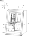
- FIG. 1 is a perspective view of a dental cutting machine 10 (hereinafter referred to simply as a "cutting machine 10") according to one embodiment.
- a direction away from the cutting machine 10 will be referred to as forward, and a direction toward the cutting machine 10 will be referred to as rearward.
- Left, right, up, and down respectively refer to left, right, up, and down when the cutting machine 10 is seen from the front.
- Characters F, Rr, L, R, U, and D in the drawings represent front, rear, left, right, up, and down, respectively.
- the cutting machine 10 is a cutting machine that performs machining on a disc-shaped machined object held by an adaptor.
- FIG. 2 is a plan view of a machined object 1 and an adaptor 5.
- the cutting machine 10 herein is a device that produces dental products such as crown prosthetics such as crowns, bridges, copings, inlays, onlays, veneers, and custom abutments, artificial teeth, denture bases, and other products, by cutting the machined object 1.
- the cutting machine 10 according to this embodiment is a dry-type cutting machine using no coolant.
- constituents of the machined object 1 include resins such as PMMA, PEEK, glass fiber reinforced resin, and hybrid resin, ceramic materials such as glass ceramic and zirconia, metal materials such as cobalt-chromium sintered metal, wax, and gypsum.
- resins such as PMMA, PEEK, glass fiber reinforced resin, and hybrid resin
- ceramic materials such as glass ceramic and zirconia
- metal materials such as cobalt-chromium sintered metal, wax, and gypsum.
- zirconia as a material for the machined object 1
- semi-sintered zirconia is used, for example.
- the machined object 1 herein has a disc (disk) shape.
- the machined object 1 may have another shape such as a block shape (e.g., cube or rectangular solid) .
- the adaptor 5 holds the disc-shaped machined object 1.
- the adaptor 5 herein is a flat-plate adaptor in which a substantially circular insertion hole 5a corresponding to the machined object 1 is formed at the center. The machined object 1 is inserted in the insertion hole 5a to be thereby held by the adaptor 5. The machined object 1 is housed in the cutting machine 10 and machined while being held by the adaptor 5.
- the cutting machine 10 includes a box-shaped casing 11.
- FIG. 3 is a longitudinal cross-sectional view of the cutting machine 10 when seen from the left.
- the cutting machine 10 includes a cutter 20 that holds a rod-shaped cutting tool 6 and rotates the cutting tool 6 about an axis, a workpiece holder 30 that holds a machined object 1 (see FIG. 2 ), a mover 40 that moves the cutter 20 and the workpiece holder 30 to thereby move the cutting tool 6 relative to the workpiece holder 30, and a controller 60 (see FIG. 1 ).
- the mover 40 includes a rotator 50 that changes orientation of the workpiece holder 30 relative to the cutting tool 6 in addition to a device that translates the cutter 20 relative to the workpiece holder 30.
- the cutter 20, the workpiece holder 30, the mover 40 including the rotator 50, and the controller 60 are housed in the casing 11.
- the cutter 20 includes the cutting tool 6 such that the axis thereof extends in predetermined Z-axis directions.
- the cutter 20 is an example of a tool holder that holds the cutting tool 6.
- the Z-axis directions herein are oblique top-bottom directions that tilt rearward.
- the workpiece holder 30 is located below the cutter 20.
- the workpiece holder 30 is located in a machining chamber 12 in which machining is performed on the machined object 1.
- a machining chamber door 13 is attached to a front opening portion of the machining chamber 12 to be freely opened and closed.
- the mover 40 includes a Z-axis direction mover 40Z that moves the cutter 20 in the Z-axis directions.
- the mover 40 further includes a Y-axis direction mover 40Y that moves the cutter 20 in Y-axis directions and an X-axis direction mover 40X that moves the workpiece holder 30 and the rotator 50 in X-axis directions.
- the X-axis directions are orthogonal to the Z-axis directions, and are herein oblique front-rear directions that tilt downward toward the rear.
- the Y-axis directions are orthogonal to the Z-axis directions and the X-axis directions, and are herein the left-right directions.
- the cutter 20 includes a main shaft 21 that grips and rotates the cutting tool 6.
- the main shaft 21 includes a spindle unit 22 and a gripper 23 located at a lower end portion of the spindle unit 22.
- the spindle unit 22 extends in the Z-axis directions.
- the spindle unit 22 rotates the gripper 23 about an axis parallel to the Z-axis directions.
- the spindle unit 22 is a unit incorporating a motor herein.
- the spindle unit 22 may be connected to, for example, an external motor by a belt or the like.
- the gripper 23 is, for example, an air-driven collet chuck.
- the type of the gripper 23 is not particularly limited.
- FIG. 4 is a plan view of the workpiece holder 30 and the rotator 50.
- the workpiece holder 30 includes a pair of left and rightward arms 31.
- the adaptor 5 is inserted between the pair of arms 31 to be thereby held by the workpiece holder 30.
- the workpiece holder 30 herein holds the machined object 1 through the adaptor 5.
- the workpiece holder 30 may directly hold the machined object 1 without intervention of other members.
- directions along which the rotation shaft 51B extends will be also referred to as B-axis directions, and rotation about the rotation shaft 51B will be also referred to rotation about the B axis.
- the B-axis directions are parallel to the Y-axis directions.
- the rotator 50B will be also referred to as a B-axis rotator 50B.
- the B-axis rotator 50B includes a B-axis rotation motor 52B (see FIG. 5 ) that rotates the rotation shaft 51B.
- the B-axis rotator 50B supports the A-axis rotator 50A, and rotates the A-axis rotator 50A about the B axis.
- the A-axis rotator 50A supports the workpiece holder 30, and rotates the workpiece holder 30 about the A axis.
- the rotation range of the A-axis rotator 50A is a full circumference (360 degrees), whereas the rotation range of the B-axis rotator 50B is smaller than 360 degrees.
- the angles of the rotation shaft 51A and the rotation shaft 51B at which one surface of the machined object 1 extends in the X-axis directions and the Y-axis directions (orthogonal to the Z-axis directions) in a machining program will be hereinafter referred to as 0 degrees. However, this designation is merely defined for convenience.
- the Z-axis direction mover 40Z supports the cutter 20 such that the cutter 20 is movable in the Z-axis directions.
- the Y-axis direction driving motor 43Y is driven, the ball screw rotates, and the Y-axis direction moving body 42Y, the Z-axis direction mover 40Z, and the cutter 20 move in the Y-axis directions along the Y-axis guide rails 41Y.
- the Z-axis direction mover 40Z also has a configuration similar to that of the Y-axis direction mover 40Y.
- the X-axis direction mover 40X is located at the right of a right wall 12R of the machining chamber 12.
- the X-axis direction mover 40X also includes guide rails extending in the X-axis directions, an X-axis direction moving body slidably engaged with the guide rails, an X-axis direction driving motor 43X (see FIG. 5 ), and a ball screw.
- the X-axis direction moving body supports the rotator 50. When the X-axis direction driving motor 43X is driven, the ball screw rotates, and the rotator 50 and the workpiece holder 30 move in the X-axis directions, together with the X-axis direction moving body.
- the configuration of the controller 60 is not particularly limited.
- the controller 60 is, for example, a microcomputer.
- a hardware configuration of the microcomputer is not particularly limited.
- the microcomputer may include, for example, an interface (I/F) that receives cutting data and other data from external equipment such as a host computer, a central processing unit (CPU) that executes an instruction of a control program, a read only memory (ROM) that stores programs to be executed by the CPU, a random access memory (RAM) that is used as a working area where programs are developed, and a storage such as a memory that stores the programs, the data, and so forth.
- I/F interface
- CPU central processing unit
- ROM read only memory
- RAM random access memory
- storage such as a memory that stores the programs, the data, and so forth.
- the machining controller 62 controls the cutter 20 and the mover 40 based on the machining program and causes the correction piece 100 to be machined.
- a measurement result of dimensions of a predetermined portion of the correction piece 100 is input to the input section 63.
- the calculator 64 calculates a correction value to be set in the mover 40 based on a result input to the input section 63.
- the corrector 65 sets the correction value calculated by the calculator 64 in the mover 40.
- the controller 60 may include other machining parts, but these parts are neither illustrated nor described herein.
- the cutting machine 10 may be configured such that a correction value calculated in an external unit based on measured dimensions of the correction piece 100 can be input to the cutting machine 10.
- a main part for calculating a correction value may be, for example, a calculator in which software for calculating a correction value is installed or an operator who performs correction work.
- a correction method for the cutting machine 10 includes: a program step of inputting a machining program of the correction piece 100 to the cutting machine 10; a mounting step of mounting a material (machined object 1 herein) for the correction piece 100 to the cutting machine 10 to which the machining program has been input; a machining step of machining the correction piece 100 from the material by the cutting machine 10 based on the machining program; a measurement step of measuring a dimension of a predetermined portion of the correction piece 100 machined in the machining step; a calculation step of calculating a correction value based on the dimension measured in the measurement step; and an input step of inputting the correction value calculated in the calculation step to the cutting machine 10.
- a main part or a method that performs each step is not particularly limited.
- the correction process of the cutting machine 10 includes a first stage including a first mounting step, a first machining step, a first measurement step, a first calculation step, and a first input step, and a second stage including a second mounting step, a second machining step, a second measurement step, a second calculation step, and a second input step.
- the second stage is performed after the first stage. First, the first stage will be described.
- FIG. 6 is a flowchart of the first stage.
- the first stage includes a program step S10, a first mounting step S11, a first machining step S12, a first measurement step S13, a first calculation step S14, and a first input step S15.
- the program step S10 is included in the first stage for convenience of the drawing, but does not need to be performed in every correction work, and basically only needs to be performed once.
- a machining program of the correction piece 100 is input to the cutting machine 10.
- the machining program includes a first machining program for machining a first correction piece 100A (see FIG. 7 ) produced in the first machining step S12, and a second machining program for machining a second correction piece 100B (see FIG. 11 ) from the first correction piece 100A in the second stage.
- a material for the correction piece 100 which is a disc-shaped machined object 1 attached to the adaptor 5 herein, is mounted to the cutting machine 10 to which the machining program of the correction piece 100 has been input.
- the material for the machined object 1 is preferably an easy-cutting material, for example, wax.
- the easy-cutting material refers to a material having high dimensional reproducibility after cutting and is less likely to cause wear on the cutting tool 6.
- Mounting orientation (bottom and top, front and rear, and left and right orientations) of the machined object 1 to the cutting machine 10 is not particularly limited.
- FIG. 7 is a plan view of the first correction piece 100A.
- FIG. 8 is a cross-sectional view of the first correction piece 100A. As illustrated in FIGS. 7 and 8 , in the first correction piece 100A, recesses 101Rr through 101L are machined in the 0 o'clock, 3 o'clock, 6 o'clock, and 9 o'clock positions, with the rearward direction along the X-axis directions considered as the 0 o'clock position.
- the recess in the 0 o'clock position will be also referred to as a rear recess 101Rr
- the recess in the 3 o'clock position will be also referred to as a right recess 101R
- the recess in the 6 o'clock position will be also referred to as a front recess 101F
- the recess in the 9 o'clock position will be also referred to as a left recess 101L.
- the right recess 101R is located rightward of the rotation shaft 51A (represented as the axis A in FIG.
- the right recess 101R and the left recess 101L herein are symmetrically located in the left-right direction with respect to the rotation shaft 51A.
- the front recess 101F is located forward of the rotation shaft 51B (represented as the axis B in FIG. 7 ) of the B-axis rotator 50B in the X-axis directions, and the rear recess 101Rr is located rearward of the rotation shaft 51B in the X-axis directions.
- the front recess 101F and the rear recess 101Rr are symmetrically located in the front-rear direction (symmetrically in the front-rear direction along the X-axis directions) with respect to the rotation shaft 51B.
- FIG. 8 is a longitudinal cross-sectional view of the first correction piece 100A taken along a plane passing through the right recess 101R and the left recess 101L and extending in the Z-axis directions.
- a bottom portion 102R of the right recess 101R and a bottom portion 102L of the left recess 101L are flat.
- the bottom portion 102R of the right recess 101R and the bottom portion 102L of the left recess 101L extend in the X-axis directions and the Y-axis directions, respectively.
- the cross section is not shown, similarly, the bottom portions of the front recess 101F and the rear recess 101Rr are also flat.
- a bottom-side right recess 103R and a bottom-side left recess 103L corresponding to the right recess 101R and the left recess 101L are formed on the bottom sides of the right recess 101R and the left recess 101L.
- a bottom portion 104R of the bottom-side right recess 103R and a bottom portion 104L of the bottom-side left recess 103L are also flat.
- the right pair of upper and lower bottom portions 102R and 104R defines an upper end and a lower end of an uncut portion between the bottom portions, and defines a thickness TR of the uncut portion.
- the left pair of upper and lower bottom portions 102L and 104L defines an upper end and a lower end of an uncut portion of the bottom portions, and defines a thickness TL of the uncut portion.
- the cross section is not shown, similar recesses are also formed on the bottom sides of the front recess 101F and the rear recess 101Rr.
- the first machining program forms one or more first flat surfaces extending in the X-axis directions and the Y-axis directions on each of one side and the other side of the rotation shaft 51A in the Y-axis directions (right side and left side herein) by the cutting tool 6 in a state where the workpiece holder 30 is held at a predetermined first angle about the rotation shaft 51A of the A-axis rotator 50A. Accordingly, the bottom portion 102R of the right recess 101R and the bottom portion 102L of the left recess 101L are formed as the first flat surfaces.
- the first machining program herein forms the first flat surfaces 102R and the 102L (bottom portions 102R and 102L) at the right and left of the rotation shaft 51A by the cutting tool 6 in a state where the workpiece holder 30 is held in a 0-degree position about the rotation shaft 51A.
- the first angle is not limited to 0 degrees.
- the first flat surfaces 102R and 102L (bottom portions 102R and 102L) only need to sandwich the rotation shaft 51A and do not need to be symmetrically located in the left-right direction with respect to the rotation shaft 51A.
- the first machining program forms second flat surfaces extending in the X-axis directions and the Y-axis directions on the bottom sides of the plurality of first flat surfaces by the cutting tool 6 in a state where the workpiece holder 30 is held at a second angle shifted from the first angle by 180 degrees.
- the bottom portion 104R of the bottom-side right recess 103R and the bottom portion 104L of the bottom-side left recess 103L are formed as the second flat surfaces.
- the first machining program herein forms the second flat surfaces 104R and 104L (bottom portions 104R and 104L) on the bottom sides of the first flat surfaces 102R and 102L (bottom portions 102R and 102L) by the cutting tool 6 in a state where the workpiece holder 30 is held in the 180-degree position about the rotation shaft 51A.
- the first machining program also forms the front recess 101F, the rear recess 101Rr, an unillustrated bottom-side front recess, and an unillustrated bottom-side rear recess in a similar manner.
- the rotation angle of the B-axis rotator 50B is set at 0 degrees.
- the work of turning over the machined object 1 is performed by rotation about the A axis by the A-axis rotator 50A.
- the thicknesses TR and TL are measured and a difference between the thicknesses is obtained, thereby calculating a shift of the rotation angle of the A-axis rotator 50A.
- a correction value for correcting the shift of the rotation angle of the A-axis rotator 50A is calculated.
- the correction value concerning the rotation angle of the A-axis rotator 50A calculated in the first calculation step S14 is input to the cutting machine 10.
- the terms "calculation" and "input” of a correction value can include automatic calculation and automatic input of a correction value by the cutting machine 10.
- the correction value includes a correction value concerning the rotation angle about the rotation shaft 51A of the A-axis rotator 50A, and this correction value is a correction value for eliminating a difference between the thicknesses TR and TL measured in the first measurement step S13.
- This correction value is set in the cutting machine 10 so that a shift of the rotation angle about the rotation shaft 51A of the A-axis rotator 50A can be thereby corrected.
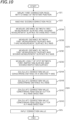
- FIG. 10 is a flowchart of the second stage.
- the second stage includes a second mounting step S21, a second machining step S22, a second measurement step S23, a second calculation step S24, and a second input step S25.
- the cutting machine 10 obtains the second correction piece 100B from the first correction piece 100A by machining.
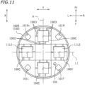
- FIG. 11 is a plan view of the second correction piece 100B.
- the front measurement piece 100C and the rear measurement piece 100C are symmetrically located in the front-rear direction (front-rear direction along the X-axis directions) with respect to the rotation shaft 51B (represented as the line L1 in FIG. 11 ).
- the measurement pieces 100C are separated from the disc by cutting a support 100D. Although not shown, identification signs are machined on the four measurement pieces 100C.
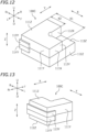
- FIG. 12 is a perspective view of the measurement piece 100C seen from the front.
- FIG. 13 is a perspective view of the measurement piece 100C seen from the rear.
- the measurement pieces 100C includes two planes 111X and 112X having different coordinates in the X-axis directions and each extending in the Y-axis directions and the Z-axis directions. These two planes will be hereinafter referred to as a first measurement surface 111X in the X-axis directions and a second measurement surface 112X in the X-axis directions.
- a coordinate of the first measurement surface 111X in the X-axis directions is a first X coordinate
- a coordinate of the second measurement surface 112X in the X-axis directions is a second X coordinate.
- the second machining program forms the first measurement surface 111X whose coordinate in the X-axis directions is the first X coordinate and the second measurement surface 112X whose coordinate in the X-axis directions is the second X coordinate by the cutting tool 6 on the second correction piece 100B.
- the measurement piece 100C in a manner similar to the X-axis directions, in the Y-axis directions, the measurement piece 100C includes two planes 111Y and 112Y having different coordinates in the Y-axis directions and each extending in the X-axis directions and the Z-axis directions. These two planes will be hereinafter referred to as a first measurement surface 111Y in the Y-axis directions and a second measurement surface 112Y in the Y-axis directions.
- a coordinate of the first measurement surface 111Y in the Y-axis directions is a first Y coordinate
- a coordinate of the second measurement surface 112Y in the Y-axis directions is a second Y coordinate.
- the second machining program forms the first measurement surface 111Y whose coordinate in the Y-axis directions is the first Y coordinate and the second measurement surface 112Y whose coordinate in the Y-axis directions is the second Y coordinate by the cutting tool 6 on the second correction piece 100B.
- the measurement piece 100C includes a first measurement surface 111Z, a second measurement surface 112Z, and a third measurement surface 113Z having different coordinates in the Z-axis directions and each extending in the X-axis directions and the Y-axis directions.
- a coordinate of the first measurement surface 111Z in the Z-axis directions is a first Z coordinate
- a coordinate of the second measurement surface 112Z in the Z-axis directions is a second Z coordinate
- a coordinate of the third measurement surface 113Z in the Z-axis directions is a third Z coordinate.
- the second machining program forms the second measurement surface 112Z whose coordinate in the Z-axis directions is the second Z coordinate by the cutting tool 6 in a state where the workpiece holder 30 is held in the 180-degree position shifted from the 0-degree position by 180 degrees.
- the second measurement surface 112Z is formed in a state where the workpiece holder 30 reversely rotates about the A axis by 180 degrees from the state in forming the first measurement surface 111Z and the third measurement surface 113Z.
- the first Z coordinate and the second Z coordinate may be the same coordinate as long as these coordinates are seen as coordinates in the Z-axis directions. However, the first measurement surface 111Z and the second measurement surface 112Z formed on the measurement piece 100C are located at different positions in the Z-axis directions.
- the second machining program forms the second inspection surface 114Y extending in the Z-axis directions by the cutting tool 6 on the second correction piece 100B in a state where the workpiece holder 30 is held at an angle shifted from the predetermined angle by 180 degrees and is held in the predetermined position in the Y-axis directions (the same position as when the first inspection surface 113Y is formed). That is, the first inspection surface 113Y and the second inspection surface 114Y are formed with the workpiece holder 30 inversely rotated about the A axis.
- the first inspection surface 113Y and the second inspection surface 114Y are flush with each other. If the position of the Y-axis origin relative to the rotation shaft 51A of the A-axis rotator 50A is shifted, in the second correction piece 100B, a shift occurs between the position of the first inspection surface 113Y in the Y-axis directions and the position of the second inspection surface 114Y in the Y-axis directions. As a result, a step occurs between the first inspection surface 113Y and the second inspection surface 114Y.
- a correction value concerning a distance in the X-axis directions, a correction value concerning a distance in the Y-axis directions, a correction value concerning a distance in the Z-axis directions, a correction value concerning a position of the cutter 20 in the Z-axis directions relative to the rotation shaft 51A of the A-axis rotator 50A, and a correction value concerning a position of the cutter 20 in the Y-axis directions relative to the rotation shaft 51A are calculated.
- step S24A the step of calculating a correction value concerning a distance in the X-axis directions and a correction value concerning a distance in the Y-axis directions
- step S24B The step of calculating a correction value concerning a distance in the Z-axis directions
- step S24C and step S24D The step of calculating a correction value concerning a position of the cutter 20 in the Y-axis directions relative to the rotation shaft 51A.
- the correction values concerning the distances in the X-axis directions and the Y-axis directions in step S24A are herein calculated after correction concerning the rotation angle of the A-axis rotator 50A.
- the correction concerning the rotation angle of the A-axis rotator 50A is performed in the first input step S15 in the first stage.
- the correction values concerning the distances in the X-axis directions and the Y-axis directions do not depend on accuracy of the rotation angle of the A-axis rotator 50A, and thus, the correction values concerning the distances in the X-axis directions and the Y-axis directions may be calculated before correction concerning the rotation angle of the A-axis rotator 50A.
- the steps are performed in the order described above to perform the machining step through the input step as efficiently as possible.
- step S24A a correction value for adjusting the distance between the first measurement surface 111X and the second measurement surface 112X in the machining program to an actually measured value of the distance between the first measurement surface 111X and the second measurement surface 112X (X1-X2 in the case illustrated in FIG. 12 ) is calculated.
- the distance between the first measurement surface 111X and the second measurement surface 112X in the machining program is, in other words, a difference in coordinate value between the first X coordinate and the second X coordinate.
- the correction value of the distance in the X-axis directions is a correction value for adjusting the difference in coordinate value between the first X coordinate and the second X coordinate to the distance measured in the second measurement step S23.
- step S24B a process similar to that in step S24A is performed for the Z-axis directions.
- step S24B a correction value for adjusting a distance between the first measurement surface 111Z and the third measurement surface 113Z in the machining program to an actually measured value of the distance between the first measurement surface 111Z and the third measurement surface 113Z is calculated.
- the correction value concerning the distance in the Z-axis directions does not depend on accuracy of the rotation angle of the A-axis rotator 50A, either.
- the correction value concerning the distance in the Z-axis directions may also be calculated before correction concerning the rotation angle of the A-axis rotator 50A.
- a correction value concerning the position of the cutter 20 in the Z-axis directions relative to the rotation shaft 51A is calculated.
- the correction value concerning the position of the cutter 20 in the Z-axis directions is preferably calculated after correction concerning the angle of the workpiece holder 30 and correction of the distance in the Z-axis directions, as in this embodiment. Calculation of the correction value concerning the position of the cutter 20 in the Z-axis directions may be performed independently of correction of the distance in the Z-axis directions.
- FIG. 14 is a schematic value illustrating a case where the position of the cutter 20 in the Z-axis directions relative to the rotation shaft 51A is shifted. As illustrated in FIG.
- the first measurement surface 111Z is located above the position in the machining program (indicated by chain double-dashed lines) in the Z-axis directions by Z1.
- the correction value concerning the position of the cutter 20 in the Z-axis directions is the amount of shift of the origin position in the Z-axis directions.
- the second measurement surface 112Z is also located above the position in the machining program by Z1 in the Z-axis directions (where the second measurement surface 112Z is located below the position in the machining program in FIG. 14 ).
- step S24D a correction value concerning the position of the cutter 20 in the Y-axis directions relative to the rotation shaft 51A is calculated.
- the correction value concerning the position of the cutter 20 in the Y-axis directions is preferably obtained after correction concerning the distance in the Y-axis directions in step S24A, as in this embodiment.
- Calculation of the correction value concerning the position of the cutter 20 in the Y-axis directions may be performed independently of correction of the distance in the Y-axis directions.
- FIG. 15 is a schematic view illustrating a case where the position of the cutter 20 in the Y-axis directions relative to the rotation shaft 51A is shifted.
- a coordinate of the rotation shaft 51A in the Y-axis directions coincides with the origin coordinate in the Y-axis directions (represented as the Z axis in FIG. 15 ).
- the coordinate position in the Y-axis directions relative to the second correction piece 100B changes between the state where the rotation shaft 51A is located in the 0-degree position and the state where the rotation shaft 51A is located in the 180-degree position.
- step S24D from an actually measured value Y1 of a step between the first inspection surface 113Y and the second inspection surface 114Y having the same coordinate in the Y-axis directions, a shift of the origin position in the Y-axis directions relative to the rotation shaft 51A is calculated.
- the correction value herein is equal to a half Y1/2 of a measured dimension Y1 of the step.
- the correction value is the amount of shift of the origin position in the Y-axis directions.
- the correction value concerning the position of the cutter 20 in the Y-axis directions is a correction value for eliminating the shift measured in step S23D.
- step S25 the correction value calculated in the second calculation step S24 is input to the cutting machine 10.
- the distance in the X-axis directions, the distance in the Y-axis directions, the distance in the Z-axis directions, the position of the cutter 20 in the Z-axis directions relative to the rotation shaft 51A, and the position of the cutter 20 in the Y-axis directions relative to the rotation shaft 51A are corrected.
- This configuration enables a product as designed according to the machining program can be produced again.
- the cutting machine and the correction method of the cutting machine according to one embodiment have been described above.
- the technique disclosed here can be carried out as other embodiments.
- the shape of the correction pieces and the correction work described above are merely examples, and can change depending on the configuration of the cutting machine.
- correction of portions that may include errors and correction of portions where errors are less likely to occur may be omitted.
- Correction not performed in the embodiment described above may be performed when it is preferable to perform the correction in consideration of the configuration of the cutting machine.
- the configuration of the cutting machine is not particularly limited.
- the A-axis rotator 50A and the B-axis rotator 50B are mounted on the X-axis direction moving body and moves along the X-axis directions together with the X-axis direction moving body.
- the origin position in the X-axis directions relative to the A-axis rotator 50A is less likely to be shifted, and does not need correction.
- the A-axis rotator and the B-axis rotator may not be moved by the X-axis direction mover.
- the A-axis rotator and the B-axis rotator may be fixed and the cutting tool may move also in the X-axis directions. In this case, the origin position in the X-axis directions relative to the rotation shaft (e.g., rotation shaft 51B) of the rotator may be corrected.
- the rotator may not change orientation of the workpiece holder and may change orientation of the cutting tool.
- the embodiment does not limit the present invention.
- the machined object may not be held by the cutting machine through the adaptor, and may be held directly by the cutting machine.
- the machined object as a material for the correction piece may not be a disk-shaped disc.
Landscapes
- Health & Medical Sciences (AREA)
- Engineering & Computer Science (AREA)
- General Health & Medical Sciences (AREA)
- Animal Behavior & Ethology (AREA)
- Veterinary Medicine (AREA)
- Public Health (AREA)
- Life Sciences & Earth Sciences (AREA)
- Oral & Maxillofacial Surgery (AREA)
- Dentistry (AREA)
- Epidemiology (AREA)
- Manufacturing & Machinery (AREA)
- Physics & Mathematics (AREA)
- Human Computer Interaction (AREA)
- Automation & Control Theory (AREA)
- General Physics & Mathematics (AREA)
- Automatic Control Of Machine Tools (AREA)
- Instructional Devices (AREA)
- Numerical Control (AREA)
- Milling Processes (AREA)
Abstract
Description
- The present invention relates to a correction method for a dental cutting machine and a dental cutting machine.
- Dental cutting machines that produce dental products by machined objects are known to date.
Patent Document 1, for example, discloses a dental cutting machine including a main shaft that holds and rotates a cutting tool, a holding member that holds a machined object, a rotary mechanism that rotates the holding member to change orientation of the holding member, an X1-direction movement mechanism that moves the holding member and the rotary mechanism in a front-rear direction, and a Y-direction movement mechanism and a Z1-direction movement mechanism that move the main shaft in a left-right direction and a top-bottom direction, respectively. - Patent Document 1:
JP2021-178372A - In a dental cutting machine, operational errors can occur because of aging or other reasons, resulting in manufacturing of products deviating from dimensions specified in a machining program.
- This application provides a method for correcting errors in a dental cutting machine encountering operational errors. This application also provides a dental cutting machine with a configuration advantageous for executing the provided method.
- A correction method for a dental cutting machine disclosed here includes: a program step of inputting a machining program of a correction piece to a dental cutting machine; a mounting step of mounting a material for the correction piece to the dental cutting machine to which the machining program has been input; a machining step of machining the correction piece from the material by the dental cutting machine based on the machining program; a measurement step of measuring a dimension of a predetermined portion of the correction piece machined in the machining step; a calculation step of calculating a correction value based on the dimension measured in the measurement step; and an input step of inputting the correction value calculated in the calculation step to the dental cutting machine.
- With this method, the correction piece is produced and dimensions of a predetermined portion of the correction piece are measured so that it is possible to perform correction to the dental cutting machine based on actual dimensions of the correction piece. Accordingly, operational errors of the dental cutting machine can be corrected.
- A dental cutting machine disclosed here includes: a tool holder that holds a cutting tool; a workpiece holder that holds a machined object; a mover that moves at least one of the tool holder and the workpiece holder to thereby move the cutting tool relative to the workpiece holder; and a controller that controls the mover. The controller includes a program register in which a machining program of a correction piece for correcting a position of the mover is registered, a machining controller that controls the mover based on the machining program and machines the correction piece, an input section to which a measurement result of a dimension of a predetermined portion of the correction piece is input, a calculator that calculates a correction value to be set in the mover based on the result input to the input section, and a corrector that sets the correction value calculated in the calculator in the mover.
- In this dental cutting machine, the program register in which the machining program of the correction piece is previously registered, the calculator that calculates the correction value when a measurement result of dimensions of the correction piece is input, and the corrector that sets the calculated correction value to the mover make it possible to perform correction of the dental cutting machine easily.
-
- [
FIG. 1] FIG. 1 is a perspective view of a cutting machine according to one embodiment. - [
FIG. 2] FIG. 2 is a plan view of a machined object and an adaptor. - [
FIG. 3] FIG. 3 is a longitudinal cross-sectional view of the cutting machine when seen from the left. - [
FIG. 4] FIG. 4 is a plan view of a workpiece holder and a rotator. - [
FIG. 5] FIG. 5 is a block diagram of the cutting machine. - [
FIG. 6] FIG. 6 is a flowchart of a first stage. - [
FIG. 7] FIG. 7 is a plan view of a first correction piece. - [
FIG. 8] FIG. 8 is a cross-sectional view of the first correction piece. - [
FIG. 9] FIG. 9 is a schematic view illustrating a thickness of an uncut portion in a case where a rotation angle that is 180 degrees in a machining program is actually (180-θ1) degrees. - [
FIG. 10] FIG. 10 is a flowchart of a second stage. - [
FIG. 11] FIG. 11 is a plan view of a second correction piece. - [
FIG. 12] FIG. 12 is a perspective view of a measurement piece when seen from the front. - [
FIG. 13] FIG. 13 is a perspective view of the measurement piece when seen from the rear. - [
FIG. 14] FIG. 14 is a schematic view illustrating a case where a position of a cutter in Z-axis directions relative to a rotation shaft is shifted. - [
FIG. 15] FIG. 15 is a schematic view illustrating a case where a position of the cutter in Y-axis directions relative to the rotation shaft is shifted. - A dental cutting machine according to one embodiment will be described with reference to the drawings. The embodiments described herein are, of course, not intended to limit the present invention. Elements and features having the same functions are denoted by the same reference characters, and description for the same elements and features will not be repeated or will be simplified as appropriate.
-
FIG. 1 is a perspective view of a dental cutting machine 10 (hereinafter referred to simply as a "cutting machine 10") according to one embodiment. In the following description, when thecutting machine 10 is seen from the front, a direction away from thecutting machine 10 will be referred to as forward, and a direction toward thecutting machine 10 will be referred to as rearward. Left, right, up, and down respectively refer to left, right, up, and down when thecutting machine 10 is seen from the front. Characters F, Rr, L, R, U, and D in the drawings represent front, rear, left, right, up, and down, respectively. - The
cutting machine 10 according to this embodiment is a cutting machine that performs machining on a disc-shaped machined object held by an adaptor.FIG. 2 is a plan view of amachined object 1 and anadaptor 5. Thecutting machine 10 herein is a device that produces dental products such as crown prosthetics such as crowns, bridges, copings, inlays, onlays, veneers, and custom abutments, artificial teeth, denture bases, and other products, by cutting themachined object 1. Thecutting machine 10 according to this embodiment is a dry-type cutting machine using no coolant. - Examples of constituents of the
machined object 1 include resins such as PMMA, PEEK, glass fiber reinforced resin, and hybrid resin, ceramic materials such as glass ceramic and zirconia, metal materials such as cobalt-chromium sintered metal, wax, and gypsum. In the case of using zirconia as a material for themachined object 1, semi-sintered zirconia is used, for example. Themachined object 1 herein has a disc (disk) shape. Themachined object 1 may have another shape such as a block shape (e.g., cube or rectangular solid) . - The
adaptor 5 holds the disc-shapedmachined object 1. Theadaptor 5 herein is a flat-plate adaptor in which a substantiallycircular insertion hole 5a corresponding to themachined object 1 is formed at the center. Themachined object 1 is inserted in theinsertion hole 5a to be thereby held by theadaptor 5. Themachined object 1 is housed in thecutting machine 10 and machined while being held by theadaptor 5. - As illustrated in
FIG. 1 , thecutting machine 10 includes a box-shaped casing 11.FIG. 3 is a longitudinal cross-sectional view of thecutting machine 10 when seen from the left. As illustrated inFIG. 3 , thecutting machine 10 includes acutter 20 that holds a rod-shaped cutting tool 6 and rotates thecutting tool 6 about an axis, aworkpiece holder 30 that holds a machined object 1 (seeFIG. 2 ), amover 40 that moves thecutter 20 and theworkpiece holder 30 to thereby move thecutting tool 6 relative to theworkpiece holder 30, and a controller 60 (seeFIG. 1 ). Themover 40 includes arotator 50 that changes orientation of theworkpiece holder 30 relative to thecutting tool 6 in addition to a device that translates thecutter 20 relative to theworkpiece holder 30. Thecutter 20, the workpiece holder 30, themover 40 including therotator 50, and thecontroller 60 are housed in thecasing 11. - As illustrated in
FIG. 3 , thecutter 20 includes thecutting tool 6 such that the axis thereof extends in predetermined Z-axis directions. Thecutter 20 is an example of a tool holder that holds thecutting tool 6. The Z-axis directions herein are oblique top-bottom directions that tilt rearward. Theworkpiece holder 30 is located below thecutter 20. Theworkpiece holder 30 is located in amachining chamber 12 in which machining is performed on themachined object 1. As illustrated inFIG. 1 , amachining chamber door 13 is attached to a front opening portion of themachining chamber 12 to be freely opened and closed. Themover 40 includes a Z-axis direction mover 40Z that moves thecutter 20 in the Z-axis directions. Themover 40 further includes a Y-axis direction mover 40Y that moves thecutter 20 in Y-axis directions and anX-axis direction mover 40X that moves theworkpiece holder 30 and therotator 50 in X-axis directions. The X-axis directions are orthogonal to the Z-axis directions, and are herein oblique front-rear directions that tilt downward toward the rear. The Y-axis directions are orthogonal to the Z-axis directions and the X-axis directions, and are herein the left-right directions. - As illustrated in
FIG. 3 , thecutter 20 includes amain shaft 21 that grips and rotates thecutting tool 6. Themain shaft 21 includes aspindle unit 22 and agripper 23 located at a lower end portion of thespindle unit 22. Thespindle unit 22 extends in the Z-axis directions. Thespindle unit 22 rotates thegripper 23 about an axis parallel to the Z-axis directions. Thespindle unit 22 is a unit incorporating a motor herein. Thespindle unit 22 may be connected to, for example, an external motor by a belt or the like. Thegripper 23 is, for example, an air-driven collet chuck. The type of thegripper 23 is not particularly limited. -
FIG. 4 is a plan view of theworkpiece holder 30 and therotator 50. As illustrated inFIG. 4 , theworkpiece holder 30 includes a pair of left andrightward arms 31. Theadaptor 5 is inserted between the pair ofarms 31 to be thereby held by theworkpiece holder 30. Theworkpiece holder 30 herein holds the machinedobject 1 through theadaptor 5. Theworkpiece holder 30 may directly hold the machinedobject 1 without intervention of other members. - The
rotator 50 includes arotator 50A that rotates theworkpiece holder 30 about arotation shaft 51A extending in the X-axis directions, and arotator 50B that rotates theworkpiece holder 30 about a rotation shaft 51B extending in the Y-axis directions. In the following description, regarding rotation of theworkpiece holder 30, directions along which therotation shaft 51A extends will be also referred to as A-axis directions, and rotation about therotation shaft 51A will be also referred to as rotation about an A axis. The A-axis directions are parallel to the X-axis directions. Therotator 50A will be also referred to as anA-axis rotator 50A. TheA-axis rotator 50A includes anA-axis rotation motor 52A that rotates therotation shaft 51A. - Similarly, in the following description, regarding rotation of the
workpiece holder 30, directions along which the rotation shaft 51B extends will be also referred to as B-axis directions, and rotation about the rotation shaft 51B will be also referred to rotation about the B axis. The B-axis directions are parallel to the Y-axis directions. Therotator 50B will be also referred to as a B-axis rotator 50B. The B-axis rotator 50B includes a B-axis rotation motor 52B (seeFIG. 5 ) that rotates the rotation shaft 51B. As illustrated inFIG. 4 , the B-axis rotator 50B supports theA-axis rotator 50A, and rotates theA-axis rotator 50A about the B axis. TheA-axis rotator 50A supports theworkpiece holder 30, and rotates theworkpiece holder 30 about the A axis. The rotation range of theA-axis rotator 50A is a full circumference (360 degrees), whereas the rotation range of the B-axis rotator 50B is smaller than 360 degrees. The angles of therotation shaft 51A and the rotation shaft 51B at which one surface of the machinedobject 1 extends in the X-axis directions and the Y-axis directions (orthogonal to the Z-axis directions) in a machining program will be hereinafter referred to as 0 degrees. However, this designation is merely defined for convenience. - As illustrated in
FIG. 3 , the Y-axis direction mover 40Y includes a pair of Y-axis guide rails 41Y extending in the Y-axis directions, a Y-axisdirection moving body 42Y slidably engaged with the Y-axis guide rails 41Y, a Y-axisdirection driving motor 43Y (seeFIG. 5 ), and an unillustrated ball screw. The Y-axisdirection moving body 42Y is movable in the Y-axis directions along the Y-axis guide rails 41Y. The Y-axisdirection moving body 42Y supports the Z-axis direction mover 40Z. The Z-axis direction mover 40Z supports thecutter 20 such that thecutter 20 is movable in the Z-axis directions. When the Y-axisdirection driving motor 43Y is driven, the ball screw rotates, and the Y-axisdirection moving body 42Y, the Z-axis direction mover 40Z, and thecutter 20 move in the Y-axis directions along the Y-axis guide rails 41Y. The Z-axis direction mover 40Z also has a configuration similar to that of the Y-axis direction mover 40Y. The Z-axis direction mover 40Z includes Z-axis guide rails 41Z extending in the Z-axis directions, a Z-axisdirection moving body 42Z slidably engaged with the Z-axis guide rails 41Z, a Z-axisdirection driving motor 43Z, and an unillustrated ball screw. When the Z-axisdirection driving motor 43Z is driven, the ball screw rotates, and the Z-axisdirection moving body 42Z and thecutter 20 move in the Z-axis directions. - Although not shown in detail, the
X-axis direction mover 40X is located at the right of aright wall 12R of themachining chamber 12. In a manner similar to the Y-axis direction mover 40Y and the Z-axis direction mover 40Z, theX-axis direction mover 40X also includes guide rails extending in the X-axis directions, an X-axis direction moving body slidably engaged with the guide rails, an X-axisdirection driving motor 43X (seeFIG. 5 ), and a ball screw. The X-axis direction moving body supports therotator 50. When the X-axisdirection driving motor 43X is driven, the ball screw rotates, and therotator 50 and theworkpiece holder 30 move in the X-axis directions, together with the X-axis direction moving body. - In this embodiment, the
mover 40 moves thecutter 20 in the Z-axis directions and the Y-axis directions and moves theworkpiece holder 30 and therotator 50 in the X-axis directions. However, the configuration of themover 40 is not limited to the embodiment described above. It is sufficient for the Z-axis direction mover 40Z to move thecutter 20 in the Z-axis directions relative to theworkpiece holder 30 by moving at least one of thecutter 20 and a set of theworkpiece holder 30 and therotator 50, and which of thecutter 20 or the set of theworkpiece holder 30 and therotator 50 is to be moved is not limited. Similarly, it is sufficient for the Y-axis direction mover 40Y to move thecutter 20 in the Y-axis directions relative to theworkpiece holder 30 and therotator 50 by moving at least one of thecutter 20 and a set of theworkpiece holder 30 and therotator 50. It is sufficient for theX-axis direction mover 40X to move theworkpiece holder 30 and therotator 50 in the X-axis directions relative to thecutter 20 by moving at least one of thecutter 20 and a set of theworkpiece holder 30 and therotator 50. -
FIG. 5 is a block diagram of the cuttingmachine 10. As illustrated inFIG. 5 , thecontroller 60 is connected to thespindle unit 22 and thegripper 23 of thecutter 20, the X-axisdirection driving motor 43X of theX-axis direction mover 40X, the Y-axisdirection driving motor 43Y of the Y-axis direction mover 40Y, the Z-axisdirection driving motor 43Z of the Z-axis direction mover 40Z, theA-axis rotation motor 52A of theA-axis rotator 50A, and the B-axis rotation motor 52B of the B-axis rotator 50B, and controls these members. - The configuration of the
controller 60 is not particularly limited. Thecontroller 60 is, for example, a microcomputer. A hardware configuration of the microcomputer is not particularly limited. The microcomputer may include, for example, an interface (I/F) that receives cutting data and other data from external equipment such as a host computer, a central processing unit (CPU) that executes an instruction of a control program, a read only memory (ROM) that stores programs to be executed by the CPU, a random access memory (RAM) that is used as a working area where programs are developed, and a storage such as a memory that stores the programs, the data, and so forth. - As illustrated in
FIG. 5 , thecontroller 60 includes aprogram register 61, amachining controller 62, aninput section 63, acalculator 64, and acorrector 65. In theprogram register 61, a machining program of a correction piece 100 (seeFIGS. 7 and11 ) for position correction of themover 40 is registered. The "position of themover 40" herein includes positions of theX-axis direction mover 40X, the Y-axis direction mover 40Y, and the Z-axis direction mover 40Z and rotation positions of theA-axis rotator 50A and the B-axis rotator 50B. The "position correction" herein includes correction of coordinates of a specific point such as an origin and correction of adjusting a distance and an angle on coordinates to an actual distance and an actual angle. In a dental cutting machine, operational errors can occur because of aging or other reasons, resulting in manufacturing of products deviating from dimensions specified in a machining program. The position correction of themover 40 is work of correcting such errors and modifying the state of the cuttingmachine 10 to produce a product with dimensions as specified in the machining program. The contents of the "position of the mover" and the "position correction" can vary depending on the configuration of the cutter and the contents of correction. - The
correction piece 100 is set at a predetermined shape and is a product obtained by cutting the machinedobject 1, and dimensions of a predetermined portion of thecorrection piece 100 are measured. The position of themover 40 is corrected based on measured dimensions of thecorrection piece 100. Thecorrection piece 100 will be described in detail later. The program register 61 may store machining data of a product other than thecorrection piece 100. - The
machining controller 62 controls thecutter 20 and themover 40 based on the machining program and causes thecorrection piece 100 to be machined. A measurement result of dimensions of a predetermined portion of thecorrection piece 100 is input to theinput section 63. Thecalculator 64 calculates a correction value to be set in themover 40 based on a result input to theinput section 63. Thecorrector 65 sets the correction value calculated by thecalculator 64 in themover 40. Thecontroller 60 may include other machining parts, but these parts are neither illustrated nor described herein. - The cutting
machine 10 may be configured such that a correction value calculated in an external unit based on measured dimensions of thecorrection piece 100 can be input to the cuttingmachine 10. In this case, a main part for calculating a correction value may be, for example, a calculator in which software for calculating a correction value is installed or an operator who performs correction work. A correction method for the cuttingmachine 10 includes: a program step of inputting a machining program of thecorrection piece 100 to the cuttingmachine 10; a mounting step of mounting a material (machinedobject 1 herein) for thecorrection piece 100 to the cuttingmachine 10 to which the machining program has been input; a machining step of machining thecorrection piece 100 from the material by the cuttingmachine 10 based on the machining program; a measurement step of measuring a dimension of a predetermined portion of thecorrection piece 100 machined in the machining step; a calculation step of calculating a correction value based on the dimension measured in the measurement step; and an input step of inputting the correction value calculated in the calculation step to the cuttingmachine 10. A main part or a method that performs each step is not particularly limited. - An example of machining of the
correction piece 100 and a correction process of the cuttingmachine 10 using thecorrection piece 100 will now be described. The process described below is merely an example, and the correction process of the cuttingmachine 10 is not limited to this example. - In this embodiment, the correction process of the cutting
machine 10 includes a first stage including a first mounting step, a first machining step, a first measurement step, a first calculation step, and a first input step, and a second stage including a second mounting step, a second machining step, a second measurement step, a second calculation step, and a second input step. The second stage is performed after the first stage. First, the first stage will be described. -
FIG. 6 is a flowchart of the first stage. As shown inFIG. 6 , the first stage includes a program step S10, a first mounting step S11, a first machining step S12, a first measurement step S13, a first calculation step S14, and a first input step S15. The program step S10 is included in the first stage for convenience of the drawing, but does not need to be performed in every correction work, and basically only needs to be performed once. In the program step S10, a machining program of thecorrection piece 100 is input to the cuttingmachine 10. The machining program includes a first machining program for machining afirst correction piece 100A (seeFIG. 7 ) produced in the first machining step S12, and a second machining program for machining asecond correction piece 100B (seeFIG. 11 ) from thefirst correction piece 100A in the second stage. - In the first mounting step S11, a material for the
correction piece 100, which is a disc-shapedmachined object 1 attached to theadaptor 5 herein, is mounted to the cuttingmachine 10 to which the machining program of thecorrection piece 100 has been input. The material for themachined object 1 is preferably an easy-cutting material, for example, wax. The easy-cutting material refers to a material having high dimensional reproducibility after cutting and is less likely to cause wear on thecutting tool 6. Mounting orientation (bottom and top, front and rear, and left and right orientations) of the machinedobject 1 to the cuttingmachine 10 is not particularly limited. - In the first machining step S12, based on the first machining program, the cutting
machine 10 obtains thefirst correction piece 100A from the machinedobject 1 by machining.FIG. 7 is a plan view of thefirst correction piece 100A.FIG. 8 is a cross-sectional view of thefirst correction piece 100A. As illustrated inFIGS. 7 and8 , in thefirst correction piece 100A, recesses 101Rr through 101L are machined in the 0 o'clock, 3 o'clock, 6 o'clock, and 9 o'clock positions, with the rearward direction along the X-axis directions considered as the 0 o'clock position. In the following direction, the recess in the 0 o'clock position will be also referred to as a rear recess 101Rr, the recess in the 3 o'clock position will be also referred to as aright recess 101R, the recess in the 6 o'clock position will be also referred to as afront recess 101F, and the recess in the 9 o'clock position will be also referred to as aleft recess 101L. Theright recess 101R is located rightward of therotation shaft 51A (represented as the axis A inFIG. 7 ) of theA-axis rotator 50A in the Y-axis directions, and theleft recess 101L is located leftward of therotation shaft 51A in the Y-axis directions. Theright recess 101R and theleft recess 101L herein are symmetrically located in the left-right direction with respect to therotation shaft 51A. - The
front recess 101F is located forward of the rotation shaft 51B (represented as the axis B inFIG. 7 ) of the B-axis rotator 50B in the X-axis directions, and the rear recess 101Rr is located rearward of the rotation shaft 51B in the X-axis directions. Thefront recess 101F and the rear recess 101Rr are symmetrically located in the front-rear direction (symmetrically in the front-rear direction along the X-axis directions) with respect to the rotation shaft 51B. -
FIG. 8 is a longitudinal cross-sectional view of thefirst correction piece 100A taken along a plane passing through theright recess 101R and theleft recess 101L and extending in the Z-axis directions. As illustrated inFIG. 8 , abottom portion 102R of theright recess 101R and abottom portion 102L of theleft recess 101L are flat. Thebottom portion 102R of theright recess 101R and thebottom portion 102L of theleft recess 101L extend in the X-axis directions and the Y-axis directions, respectively. Although the cross section is not shown, similarly, the bottom portions of thefront recess 101F and the rear recess 101Rr are also flat. - As illustrated in
FIG. 8 , a bottom-sideright recess 103R and a bottom-sideleft recess 103L corresponding to theright recess 101R and theleft recess 101L are formed on the bottom sides of theright recess 101R and theleft recess 101L. Abottom portion 104R of the bottom-sideright recess 103R and abottom portion 104L of the bottom-sideleft recess 103L are also flat. The right pair of upper and lowerbottom portions bottom portions front recess 101F and the rear recess 101Rr. - The first machining program forms one or more first flat surfaces extending in the X-axis directions and the Y-axis directions on each of one side and the other side of the
rotation shaft 51A in the Y-axis directions (right side and left side herein) by thecutting tool 6 in a state where theworkpiece holder 30 is held at a predetermined first angle about therotation shaft 51A of theA-axis rotator 50A. Accordingly, thebottom portion 102R of theright recess 101R and thebottom portion 102L of theleft recess 101L are formed as the first flat surfaces. The first machining program herein forms the firstflat surfaces 102R and the 102L (bottom portions rotation shaft 51A by thecutting tool 6 in a state where theworkpiece holder 30 is held in a 0-degree position about therotation shaft 51A. The first angle is not limited to 0 degrees. The firstflat surfaces bottom portions rotation shaft 51A and do not need to be symmetrically located in the left-right direction with respect to therotation shaft 51A. - The first machining program forms second flat surfaces extending in the X-axis directions and the Y-axis directions on the bottom sides of the plurality of first flat surfaces by the
cutting tool 6 in a state where theworkpiece holder 30 is held at a second angle shifted from the first angle by 180 degrees. In this manner, thebottom portion 104R of the bottom-sideright recess 103R and thebottom portion 104L of the bottom-sideleft recess 103L are formed as the second flat surfaces. The first machining program herein forms the secondflat surfaces bottom portions flat surfaces bottom portions cutting tool 6 in a state where theworkpiece holder 30 is held in the 180-degree position about therotation shaft 51A. - The first machining program also forms the
front recess 101F, the rear recess 101Rr, an unillustrated bottom-side front recess, and an unillustrated bottom-side rear recess in a similar manner. In this case, the rotation angle of the B-axis rotator 50B is set at 0 degrees. The work of turning over the machinedobject 1 is performed by rotation about the A axis by theA-axis rotator 50A. - As illustrated in
FIG. 7 , thefirst correction piece 100A has anidentification mark 105 for identifying right and left in the Y-axis directions. Theidentification mark 105 is a recess herein. Theidentification mark 105 is located near the top-side front recess 101F herein. Accordingly, the front side and the top side of thefirst correction piece 100A are recognized. As a result, the right side and the left side of thefirst correction piece 100A can also be recognized. If the right side and the left side of thefirst correction piece 100A are mistaken, the sign of the correction value is reversed. Theidentification mark 105 is used for preventing such an error in identifying left and right. The first machining program forms theidentification mark 105 for identifying one side from the other side in the Y-axis directions, on thefirst correction piece 100A by thecutting tool 6. - As shown in
FIG. 6 , in the first measurement step S13, the thicknesses TR and TL in the Z-axis directions between the two top-side bottom portions side bottom portions - As shown in
FIG. 6 , in the first calculation step S14, based on the dimensions measured in the first measurement step S13, a correction value concerning a rotation angle about therotation shaft 51A of theA-axis rotator 50A is calculated. The correction value concerning the rotation angle of theA-axis rotator 50A is a correction value for correcting the rotation angle based on a ratio of 180 degrees and an actually measured value obtained by determining an actual value for which the machining program specifies 180 degrees. -
FIG. 9 is a schematic view showing the thicknesses TR and TL of an uncut portion in a case where a rotation angle of 180 degrees in a counterclockwise direction in the machining program is actually (180-θ1) degrees. InFIG. 9 , the top-side recesses side recesses FIG. 9 , the 0-degree position is correct, and only the 180-degree position is shifted to a negative side by an angle θ1. It should be noted that the shift can occur in the case of the 0-degree position or in both of the cases of the 0-degree position and the 180-degree position. As illustrated inFIG. 9 , in the case where the rotation angle of theA-axis rotator 50A is shifted to a negative side, at the 180-degree position in the program, a left portion of thefirst correction piece 100A at the left of therotation shaft 51A is located above a right portion of thefirst correction piece 100A at the right of therotation shaft 51A in the Z-axis directions (where the left portion and the right portion herein refer to a left portion and a right portion when the bottom side serves as an upper surface, that is, a left portion and a right portion respectively corresponding to left and right inFIG. 9 ). Thus, the bottom-sideright recess 103R (left recess inFIG. 9 ) is cut more deeply than the bottom-sideleft recess 103L (right recess inFIG. 9 ). Accordingly, the thickness TR becomes smaller than the thickness TL. In a case where the rotation angle of theA-axis rotator 50A is shifted to a positive side, the opposite applies. - The thicknesses TR and TL are measured and a difference between the thicknesses is obtained, thereby calculating a shift of the rotation angle of the
A-axis rotator 50A. In the first calculation step S14, a correction value for correcting the shift of the rotation angle of theA-axis rotator 50A is calculated. As shown inFIG. 6 , in the first input step S15, the correction value concerning the rotation angle of theA-axis rotator 50A calculated in the first calculation step S14 is input to the cuttingmachine 10. The terms "calculation" and "input" of a correction value can include automatic calculation and automatic input of a correction value by the cuttingmachine 10. In this manner, in this embodiment, the correction value includes a correction value concerning the rotation angle about therotation shaft 51A of theA-axis rotator 50A, and this correction value is a correction value for eliminating a difference between the thicknesses TR and TL measured in the first measurement step S13. This correction value is set in the cuttingmachine 10 so that a shift of the rotation angle about therotation shaft 51A of theA-axis rotator 50A can be thereby corrected. - As shown in
FIG. 6 , in the first calculation step S14, a correction value concerning a 0-degree position of the B-axis rotator 50B is also calculated. When the 0-degree position of the B-axis rotator 50B is shifted, one of a front portion forward of the rotation shaft 51B or a rear portion rearward of the rotation shaft 51B is located above the other. Thus, for reasons similar to those illustrated inFIG. 9 , the recess of an upper one of the front portion and the rear portion is deeper than the other. Accordingly, the uncut portion of the upper one of the front portion and the rear portion is thinner than the other. Thus, an error at the 0-degree position of the B-axis rotator 50B can be obtained by obtaining a thickness difference in the uncut portion between the front portion and the rear portion. The correction value concerning the 0-degree position of the B-axis rotator 50B is an angle for correcting this error. In the first input step S15, this correction value is also input to the cuttingmachine 10. In this embodiment, in angle correction of the B-axis rotator 50B, correction of adjusting the unit angle as performed in the case of theA-axis rotator 50A is not performed. - After the first stage, the second stage of correction of the cutting
machine 10 is performed.FIG. 10 is a flowchart of the second stage. As shown inFIG. 10 , the second stage includes a second mounting step S21, a second machining step S22, a second measurement step S23, a second calculation step S24, and a second input step S25. - The second mounting step S21 is performed after the first machining step S12 through the first input step S15. In the second mounting step S21, the rotation position about the Z axis is changed from the first mounting step S11, and the machined object 1 (
first correction piece 100A) is mounted to the cuttingmachine 10. Although described in detail later, the machining program forms the plurality ofrecesses correction piece 100 in the X-axis directions and extending in the Y-axis directions (seeFIG. 7 ) in the first stage, and forms another measurement surface on the same line L1 (seeFIG. 11 ) in the second stage. In the first stage, therecesses A-axis rotator 50A is magnified to be thereby easily measured. In the second stage, the measurement surface (specifically, afirst measurement surface 111Z in the Z-axis directions) is located on the line L1 so that the measurement surface is enlarged and, thereby, dimensions can be easily measured. To avoid overlapping of the plurality ofrecesses first correction piece 100A is mounted to the cuttingmachine 10. Rotation angle at this time is, for example, 45 degrees about the Z axis as illustrated inFIG. 11 , but the rotation angle does not need to be exact. The rotation angle in the second mounting step S21 is not particularly limited as long as a portion formed in the first stage and a portion formed in the second stage do not overlap each other. - In the case of producing the
first correction piece 100A and thesecond correction piece 100B (except a machined portion of thefirst correction piece 100A) separately, in the second mounting step S21, not thefirst correction piece 100A but a newmachined object 1 may be mounted to the cuttingmachine 10. The amount of the machinedobject 1 used in correction of the cuttingmachine 10 can be reduced by reusing thefirst correction piece 100A in the second stage. - In the second machining step S22, based on the second machining program, the cutting
machine 10 obtains thesecond correction piece 100B from thefirst correction piece 100A by machining.FIG. 11 is a plan view of thesecond correction piece 100B. - As illustrated in
FIG. 11 , in thesecond correction piece 100B, fourmeasurement pieces 100C for measuring dimensions are machined in the direction of 0 o'clock, 3 o'clock, 6 o'clock, and 9 o'clock positions, respectively. The fourmeasurement pieces 100C are separated from the disc for measuring dimensions. The fourmeasurement pieces 100C are the same pieces, and arranged in the same orientation. In addition, to eliminate influence of difference in machining accuracy (e.g., difference caused by backlash) among machining directions, the fourmeasurement pieces 100C are machined in the same direction. The plurality ofmeasurement pieces 100C can be machined under the same conditions without arrangement of themeasurement pieces 100C in the same orientation. In the following description, themeasurement piece 100C in the 0 o'clock position will be also referred to as arear measurement piece 100C, themeasurement piece 100C in the 3 o'clock position will be also referred to as aright measurement piece 100C, themeasurement piece 100C in the 6 o'clock position will be also referred to as afront measurement piece 100C, and themeasurement piece 100C in the 9 o'clock position will be also referred to as aleft measurement piece 100C. Theright measurement piece 100C and theleft measurement piece 100C are formed on the line L1. Theright measurement piece 100C and theleft measurement piece 100C are herein symmetrically located in the left-right direction with respect to therotation shaft 51A (represented as the axis A inFIG. 11 ). Thefront measurement piece 100C and therear measurement piece 100C are symmetrically located in the front-rear direction (front-rear direction along the X-axis directions) with respect to the rotation shaft 51B (represented as the line L1 inFIG. 11 ). Themeasurement pieces 100C are separated from the disc by cutting asupport 100D. Although not shown, identification signs are machined on the fourmeasurement pieces 100C. -
FIG. 12 is a perspective view of themeasurement piece 100C seen from the front.FIG. 13 is a perspective view of themeasurement piece 100C seen from the rear. As illustrated inFIGS. 12 and 13 , themeasurement pieces 100C includes twoplanes first measurement surface 111X in the X-axis directions and asecond measurement surface 112X in the X-axis directions. In the machining program, a coordinate of thefirst measurement surface 111X in the X-axis directions is a first X coordinate, and a coordinate of thesecond measurement surface 112X in the X-axis directions is a second X coordinate. The second machining program forms thefirst measurement surface 111X whose coordinate in the X-axis directions is the first X coordinate and thesecond measurement surface 112X whose coordinate in the X-axis directions is the second X coordinate by thecutting tool 6 on thesecond correction piece 100B. - As illustrated in
FIG. 12 , in a manner similar to the X-axis directions, in the Y-axis directions, themeasurement piece 100C includes twoplanes first measurement surface 111Y in the Y-axis directions and asecond measurement surface 112Y in the Y-axis directions. In the machining program, a coordinate of thefirst measurement surface 111Y in the Y-axis directions is a first Y coordinate, and a coordinate of thesecond measurement surface 112Y in the Y-axis directions is a second Y coordinate. The second machining program forms thefirst measurement surface 111Y whose coordinate in the Y-axis directions is the first Y coordinate and thesecond measurement surface 112Y whose coordinate in the Y-axis directions is the second Y coordinate by thecutting tool 6 on thesecond correction piece 100B. - In addition, the
measurement piece 100C includes afirst measurement surface 111Z, asecond measurement surface 112Z, and athird measurement surface 113Z having different coordinates in the Z-axis directions and each extending in the X-axis directions and the Y-axis directions. In the machining program, a coordinate of thefirst measurement surface 111Z in the Z-axis directions is a first Z coordinate, a coordinate of thesecond measurement surface 112Z in the Z-axis directions is a second Z coordinate, and a coordinate of thethird measurement surface 113Z in the Z-axis directions is a third Z coordinate. The second machining program forms thefirst measurement surface 111Z whose coordinate in the Z-axis directions is the first Z coordinate and thethird measurement surface 113Z whose coordinate in the Z-axis directions is the third Z coordinate by thecutting tool 6 on thesecond correction piece 100B. Thefirst measurement surface 111Z and thethird measurement surface 113Z are formed in a state where theworkpiece holder 30 is held at a predetermined angle about therotation shaft 51A. The predetermined angle herein is 0 degrees. The predetermined angle is not limited to 0 degrees. - The second machining program forms the
second measurement surface 112Z whose coordinate in the Z-axis directions is the second Z coordinate by thecutting tool 6 in a state where theworkpiece holder 30 is held in the 180-degree position shifted from the 0-degree position by 180 degrees. Thesecond measurement surface 112Z is formed in a state where theworkpiece holder 30 reversely rotates about the A axis by 180 degrees from the state in forming thefirst measurement surface 111Z and thethird measurement surface 113Z. The first Z coordinate and the second Z coordinate may be the same coordinate as long as these coordinates are seen as coordinates in the Z-axis directions. However, thefirst measurement surface 111Z and thesecond measurement surface 112Z formed on themeasurement piece 100C are located at different positions in the Z-axis directions. - As shown in
FIG. 13 , themeasurement piece 100C includes afirst inspection surface 113Y and asecond inspection surface 114Y for correcting the position of a Y-axis origin relative to therotation shaft 51A of theA-axis rotator 50A. Each of thefirst inspection surface 113Y and thesecond inspection surface 114Y extends in the X-axis directions and the Z-axis directions. The Y-axis coordinate of thefirst inspection surface 113Y and the Y-axis coordinate of thesecond inspection surface 114Y are the same in the machining program. Thefirst inspection surface 113Y and thesecond inspection surface 114Y are arranged side by side in the Z-axis directions. - The second machining program forms the
first inspection surface 113Y extending in the Z-axis directions by thecutting tool 6 on thesecond correction piece 100B in a state where theworkpiece holder 30 is held at a predetermined angle about therotation shaft 51A of theA-axis rotator 50A and is held in a predetermined position in the Y-axis directions. The predetermined angle of therotation shaft 51A herein is 0 degrees. The predetermined angle is not limited to 0 degrees. In addition, the second machining program forms thesecond inspection surface 114Y extending in the Z-axis directions by thecutting tool 6 on thesecond correction piece 100B in a state where theworkpiece holder 30 is held at an angle shifted from the predetermined angle by 180 degrees and is held in the predetermined position in the Y-axis directions (the same position as when thefirst inspection surface 113Y is formed). That is, thefirst inspection surface 113Y and thesecond inspection surface 114Y are formed with theworkpiece holder 30 inversely rotated about the A axis. - In the machining program, the
first inspection surface 113Y and thesecond inspection surface 114Y are flush with each other. If the position of the Y-axis origin relative to therotation shaft 51A of theA-axis rotator 50A is shifted, in thesecond correction piece 100B, a shift occurs between the position of thefirst inspection surface 113Y in the Y-axis directions and the position of thesecond inspection surface 114Y in the Y-axis directions. As a result, a step occurs between thefirst inspection surface 113Y and thesecond inspection surface 114Y. - As shown in
FIG. 10 , in the second measurement step S23, a distance in the X-axis directions between thefirst measurement surface 111X and thesecond measurement surface 112X in the X-axis directions is measured. Although the measurement method thereof is not particularly limited, a distance X1 between thefirst measurement surface 111X and another surface parallel to thefirst measurement surface 111X and a distance X2 between thesecond measurement surface 112X and the another surface may be measured with a micrometer so that a distance between thefirst measurement surface 111X and thesecond measurement surface 112X in the X-axis directions can be obtained from a difference between the distances X1 and X2. The distance between thefirst measurement surface 111X and thesecond measurement surface 112X in the X-axis directions may be directly measured with, for example, a micrometer. - In the second measurement step S23, a distance in the Y-axis directions between the
first measurement surface 111Y and thesecond measurement surface 112Y in the Y-axis directions is measured. As shown inFIG. 10 , steps for these axes in the second measurement step S23 will be referred to as a step S23A. In step S23A, an average value is calculated from measured values obtained from the fourmeasurement pieces 100C, and the obtained average value is used as a representative value. The method for obtaining a representative value from the plurality of measured values is not limited to the average value processing. As the representative value of the measured values, a median may be employed, for example. - In the second measurement step S23, a distance in the Z-axis directions between the
first measurement surface 111Z and thethird measurement surface 113Z in the Z-axis directions is measured. Both thefirst measurement surface 111Z and thethird measurement surface 113Z are formed in the state where theworkpiece holder 30 is held in the 0-degree position. As shown inFIG. 10 , this step in the second measurement step S23 will be referred to as step S23B. In step S23B, a distance in the Z-axis directions between thesecond measurement surface 112Z and thethird measurement surface 113Z in the Z-axis directions may be measured. In step S23B, measured values obtained from the fourmeasurement pieces 100C are averaged. The method for processing a plurality of measured values is not limited to the average value processing. - In the second measurement step S23, a distance in the Z-axis directions between the
first measurement surface 111Z and thesecond measurement surface 112Z in the Z-axis directions is also measured. Thefirst measurement surface 111Z and thesecond measurement surface 112Z are formed by reversely rotating theworkpiece holder 30 about the A axis by 180 degrees. As shown inFIG. 10 , this step in the second measurement step S23 will be referred to as step S23C. In step S23C, measured values obtained from the fourmeasurement pieces 100C are averaged. The method for processing a plurality of measured values is not limited to the average value processing. - In addition, in the second measurement step S23, the amount of shift between the
first inspection surface 113Y and thesecond inspection surface 114Y in the Y-axis directions, that is, a height Y1 of a step between thefirst inspection surface 113Y and thesecond inspection surface 114Y in the Y-axis directions (seeFIG. 15 ), is measured. As shown inFIG. 10 , this step in the second measurement step S23 will be referred to as step S23D. In step S23D, measured values obtained from the fourmeasurement pieces 100C are averaged. The method for processing a plurality of measured values is not limited to the average value processing. - As shown in
FIG. 10 , in the second calculation step S24, a correction value concerning a distance in the X-axis directions, a correction value concerning a distance in the Y-axis directions, a correction value concerning a distance in the Z-axis directions, a correction value concerning a position of thecutter 20 in the Z-axis directions relative to therotation shaft 51A of theA-axis rotator 50A, and a correction value concerning a position of thecutter 20 in the Y-axis directions relative to therotation shaft 51A are calculated. As shown inFIG. 10 , the step of calculating a correction value concerning a distance in the X-axis directions and a correction value concerning a distance in the Y-axis directions will be hereinafter referred to as step S24A. The step of calculating a correction value concerning a distance in the Z-axis directions will be hereinafter referred to as step S24B. The step of calculating a correction value concerning a position of thecutter 20 in the Z-axis directions relative to therotation shaft 51A and the step of calculating a correction value concerning a position of thecutter 20 in the Y-axis directions relative to therotation shaft 51A will be referred to as step S24C and step S24D, respectively. - The correction values concerning the distances in the X-axis directions and the Y-axis directions in step S24A are herein calculated after correction concerning the rotation angle of the
A-axis rotator 50A. In this embodiment, the correction concerning the rotation angle of theA-axis rotator 50A is performed in the first input step S15 in the first stage. However, the correction values concerning the distances in the X-axis directions and the Y-axis directions do not depend on accuracy of the rotation angle of theA-axis rotator 50A, and thus, the correction values concerning the distances in the X-axis directions and the Y-axis directions may be calculated before correction concerning the rotation angle of theA-axis rotator 50A. In this embodiment, the steps are performed in the order described above to perform the machining step through the input step as efficiently as possible. - Regarding the X-axis directions, in step S24A, a correction value for adjusting the distance between the
first measurement surface 111X and thesecond measurement surface 112X in the machining program to an actually measured value of the distance between thefirst measurement surface 111X and thesecond measurement surface 112X (X1-X2 in the case illustrated inFIG. 12 ) is calculated. The distance between thefirst measurement surface 111X and thesecond measurement surface 112X in the machining program is, in other words, a difference in coordinate value between the first X coordinate and the second X coordinate. The correction value of the distance in the X-axis directions is a correction value for adjusting the difference in coordinate value between the first X coordinate and the second X coordinate to the distance measured in the second measurement step S23. For example, in a case where the actually measured value is larger than the distance in the machining program, this means that dimensions of the final product are larger than those programmed, and a correction value for reducing the length in the X-axis directions in the machining program (correction value smaller than one) is calculated. The same holds for the Y-axis directions. - In step S24B, a process similar to that in step S24A is performed for the Z-axis directions. In step S24B, a correction value for adjusting a distance between the
first measurement surface 111Z and thethird measurement surface 113Z in the machining program to an actually measured value of the distance between thefirst measurement surface 111Z and thethird measurement surface 113Z is calculated. The correction value concerning the distance in the Z-axis directions does not depend on accuracy of the rotation angle of theA-axis rotator 50A, either. Thus, the correction value concerning the distance in the Z-axis directions may also be calculated before correction concerning the rotation angle of theA-axis rotator 50A. Regarding the distances in the X-axis directions, the Y-axis directions, and the Z-axis directions, correction of a unit distance is performed. If the distances in the X-axis directions, the Y-axis directions, and the Z-axis directions are shifted, a difference between each distance in the machining program and the actually measured value increases in proportion to the distance in the machining program. - As shown in
FIG. 10 , in step S24C, a correction value concerning the position of thecutter 20 in the Z-axis directions relative to therotation shaft 51A is calculated. The correction value concerning the position of thecutter 20 in the Z-axis directions is preferably calculated after correction concerning the angle of theworkpiece holder 30 and correction of the distance in the Z-axis directions, as in this embodiment. Calculation of the correction value concerning the position of thecutter 20 in the Z-axis directions may be performed independently of correction of the distance in the Z-axis directions.FIG. 14 is a schematic value illustrating a case where the position of thecutter 20 in the Z-axis directions relative to therotation shaft 51A is shifted. As illustrated inFIG. 14 , if the position of thecutter 20 in the Z-axis directions relative to therotation shaft 51A is shifted by Z1 (assumed to be shifted by Z1 upward in the Z-axis directions herein), thefirst measurement surface 111Z is located above the position in the machining program (indicated by chain double-dashed lines) in the Z-axis directions by Z1. The correction value concerning the position of thecutter 20 in the Z-axis directions is the amount of shift of the origin position in the Z-axis directions. Similarly, thesecond measurement surface 112Z is also located above the position in the machining program by Z1 in the Z-axis directions (where thesecond measurement surface 112Z is located below the position in the machining program inFIG. 14 ). Thus, the distance between thefirst measurement surface 111Z and thesecond measurement surface 112Z measured in step S23C is larger than the distance between thefirst measurement surface 111Z and thesecond measurement surface 112Z in the Z-axis directions in the machining program by twice the value of Z1. The difference between the distance in the machining program and the actually measured value is uniform, independently of the distance in the machining program. The correction value concerning the position of thecutter 20 in the Z-axis directions is a correction value for eliminating a difference between the measured distance between thefirst measurement surface 111Z and thesecond measurement surface 112Z and the distance between thefirst measurement surface 111Z and thesecond measurement surface 112Z in the Z-axis directions in the machining program. In the case illustrated inFIG. 14 , the correction value is a correction value for shifting the origin position in the Z-axis directions downward by Z1. - In step S24D, a correction value concerning the position of the
cutter 20 in the Y-axis directions relative to therotation shaft 51A is calculated. The correction value concerning the position of thecutter 20 in the Y-axis directions is preferably obtained after correction concerning the distance in the Y-axis directions in step S24A, as in this embodiment. Calculation of the correction value concerning the position of thecutter 20 in the Y-axis directions may be performed independently of correction of the distance in the Y-axis directions.FIG. 15 is a schematic view illustrating a case where the position of thecutter 20 in the Y-axis directions relative to therotation shaft 51A is shifted. In this embodiment, a coordinate of therotation shaft 51A in the Y-axis directions coincides with the origin coordinate in the Y-axis directions (represented as the Z axis inFIG. 15 ). Thus, as illustrated inFIG. 15 , when the origin position in the Y-axis directions is shifted relative to therotation shaft 51A, the coordinate position in the Y-axis directions relative to thesecond correction piece 100B changes between the state where therotation shaft 51A is located in the 0-degree position and the state where therotation shaft 51A is located in the 180-degree position. In step S24D, from an actually measured value Y1 of a step between thefirst inspection surface 113Y and thesecond inspection surface 114Y having the same coordinate in the Y-axis directions, a shift of the origin position in the Y-axis directions relative to therotation shaft 51A is calculated. The correction value herein is equal to a half Y1/2 of a measured dimension Y1 of the step. The correction value is the amount of shift of the origin position in the Y-axis directions. In this manner, the correction value concerning the position of thecutter 20 in the Y-axis directions is a correction value for eliminating the shift measured in step S23D. - As shown in
FIG. 10 , in step S25, the correction value calculated in the second calculation step S24 is input to the cuttingmachine 10. In this manner, the distance in the X-axis directions, the distance in the Y-axis directions, the distance in the Z-axis directions, the position of thecutter 20 in the Z-axis directions relative to therotation shaft 51A, and the position of thecutter 20 in the Y-axis directions relative to therotation shaft 51A are corrected. This configuration enables a product as designed according to the machining program can be produced again. - The cutting machine and the correction method of the cutting machine according to one embodiment have been described above. The technique disclosed here can be carried out as other embodiments. For example, the shape of the correction pieces and the correction work described above are merely examples, and can change depending on the configuration of the cutting machine. Considering the configuration of the cutting machine, correction of portions that may include errors and correction of portions where errors are less likely to occur may be omitted. Correction not performed in the embodiment described above may be performed when it is preferable to perform the correction in consideration of the configuration of the cutting machine.
- The configuration of the cutting machine is not particularly limited. For example, in the embodiment described above, the
A-axis rotator 50A and the B-axis rotator 50B are mounted on the X-axis direction moving body and moves along the X-axis directions together with the X-axis direction moving body. Thus, the origin position in the X-axis directions relative to theA-axis rotator 50A is less likely to be shifted, and does not need correction. Alternatively, the A-axis rotator and the B-axis rotator may not be moved by the X-axis direction mover. For example, the A-axis rotator and the B-axis rotator may be fixed and the cutting tool may move also in the X-axis directions. In this case, the origin position in the X-axis directions relative to the rotation shaft (e.g., rotation shaft 51B) of the rotator may be corrected. The rotator may not change orientation of the workpiece holder and may change orientation of the cutting tool. - Unless otherwise specified, the embodiment does not limit the present invention. For example, the machined object may not be held by the cutting machine through the adaptor, and may be held directly by the cutting machine. The machined object as a material for the correction piece may not be a disk-shaped disc.
-
- 1
- machined object
- 6
- cutting tool
- 10
- dental cutting machine
- 20
- cutter (tool holder)
- 30
- workpiece holder
- 40
- mover
- 40X
- X-axis direction mover
- 40Y
- Y-axis direction mover
- 40Z
- Z-axis direction mover
- 50
- rotator
- 50A
- A-axis rotator
- 51A
- rotation shaft
- 50B
- B-axis rotator
- 51B
- rotation shaft
- 60
- controller
- 61
- program register
- 62
- machining controller
- 63
- input section
- 64
- calculator
- 65
- corrector
- 100
- correction piece
- 102L
- bottom portion (first flat surface) of left recess
- 102R
- bottom portion (first flat surface) of right recess
- 104L
- bottom portion (second flat surface) of bottom-side left recess
- 104R
- bottom portion (second flat surface) of bottom-side right recess
- 105
- identification mark (identifier)
- 111X
- first measurement surface in X-axis directions
- 111Y
- first measurement surface in Y-axis directions
- 111Z
- first measurement surface in Z-axis directions
- 112X
- second measurement surface in X-axis directions
- 112Y
- second measurement surface in Y-axis directions
- 112Z
- second measurement surface in Z-axis directions
- 113Z
- third measurement surface in Z-axis directions
- 113Y
- first inspection surface
- 114Y
- second inspection surface
Claims (8)
- A correction method for a dental cutting machine comprising:a program step of inputting a machining program of a correction piece to a dental cutting machine;a mounting step of mounting a material for the correction piece to the dental cutting machine to which the machining program has been input;a machining step of machining the correction piece from the material by the dental cutting machine based on the machining program;a measurement step of measuring a dimension of a predetermined portion of the correction piece machined in the machining step;a calculation step of calculating a correction value based on the dimension measured in the measurement step; andan input step of inputting the correction value calculated in the calculation step to the dental cutting machine.
- The correction method for the dental cutting machine according to claim 1, whereinthe dental cutting machine includesa tool holder that holds a cutting tool,a workpiece holder that holds the correction piece, anda mover that moves at least one of the tool holder and the workpiece holder to thereby move the cutting tool in a predetermined moving direction relative to the workpiece holder,the machining program forms a first plane whose coordinate in the moving direction is a first coordinate and a second plane whose coordinate in the moving direction is a second coordinate by the cutting tool on the correction piece,in the measurement step, a distance between the first plane and the second plane in the moving direction is measured,the correction value includes a correction value concerning the distance in the moving direction, andthe correction value concerning the distance in the moving direction is a correction value for adjusting a difference in coordinate value between the first coordinate and the second coordinate to the distance measured in the measurement step.
- The correction method for the dental cutting machine according to claim 1, whereinthe dental cutting machine includesa tool holder that holds a rod-shaped cutting tool extending in predetermined Z-axis directions,a workpiece holder that holds the material for the correction piece,a rotator that rotates the workpiece holder about a rotation shaft extending in X-axis directions orthogonal to the Z-axis directions to thereby change orientation of the workpiece holder relative to the cutting tool,a Z-axis direction mover that moves at least one of the tool holder and a set of the workpiece holder and the rotator to thereby move the tool holder in the Z-axis directions relative to the workpiece holder, anda Y-axis direction mover that moves at least one of the tool holder and the set of the workpiece holder and the rotator to thereby move the tool holder in Y-axis directions orthogonal to the Z-axis directions and the X-axis directions relative to the workpiece holder,the machining programforms one or more first flat surfaces extending in the X-axis directions and the Y-axis directions on each of one side and another side of the rotation shaft in the Y-axis directions by the cutting tool in a state where the workpiece holder is held at a predetermined first angle about the rotation shaft, andforms second flat surfaces extending in the X-axis directions and the Y-axis directions on bottom sides of the first flat surfaces by the cutting tool in a state where the workpiece holder is held at a second angle shifted from the first angle by 180 degrees,in the measurement step, thicknesses between the first flat surfaces and the second flat surfaces in the Z-axis directions are measured,the correction value includes a correction value concerning a rotation angle of the rotator about the rotation shaft, andthe correction value concerning the rotation angle of the rotator is a correction value for eliminating a difference between the thicknesses measured in the measurement step.
- The correction method for the dental cutting machine according to claim 3, wherein
the machining program forms an identifier for identifying one side and another side in the Y-axis directions, on the correction piece by the cutting tool. - The correction method for the dental cutting machine according to claim 3 or 4, whereinthe machining programforms a first measurement surface whose coordinate in the Z-axis directions is a first coordinate by the cutting tool in a state where the workpiece holder is held at a predetermined angle about the rotation shaft, andforms a second measurement surface whose coordinate in the Z-axis directions is a second coordinate by the cutting tool in a state where the workpiece holder is held at an angle shifted from the predetermined angle by 180 degrees,in the measurement step, a distance between the first measurement surface and the second measurement surface in the Z-axis directions is measured,the correction value includes a correction value concerning a position of the tool holder in the Z-axis directions relative to the rotation shaft, andthe correction value concerning the position of the tool holder in the Z-axis directions is a correction value for eliminating a difference between the measured distance between the first measurement surface and the second measurement surface and the distance between the first measurement surface and the second measurement surface in the Z-axis directions in the machining program, and is calculated after correction concerning a rotation angle of the rotator about the rotation shaft.
- The correction method for the dental cutting machine according to claim 5, whereinthe machining program forms the first flat surfaces, the second flat surfaces, the first measurement surface, and the second measurement surface on a line passing through a center of the correction piece in the X-axis directions and extending in the Y-axis directions,the machining step includesa first machining step of forming the first flat surfaces and the second flat surfaces on the correction piece, anda second machining step of forming the first measurement surface and the second measurement surface on the correction piece,the measurement step, the calculation step, and the input step includea first measurement step, a first calculation step, and a first input step, respectively, performed after the first machining step, anda second measurement step, a second calculation step, and a second input step, respectively, performed after the second machining step, andthe mounting step includesa first mounting step of mounting the material for the correction piece to the dental cutting machine before the first machining step, anda second mounting step of mounting the material to the dental cutting machine while changing a rotation position about the Z axis from the first mounting step, after the first machining step, the first measurement step, the first calculation step, and the first input step.
- The correction method for the dental cutting machine according to any one of claims 3 to 6, whereinthe machining programforms a first inspection surface extending in the Z-axis directions by the cutting tool on the correction piece in a state where the workpiece holder is held at a predetermined angle about the rotation shaft and is held in a predetermined position in the Y-axis directions, andforms a second inspection surface extending in the Z-axis directions by the cutting tool on the correction piece in a state where the workpiece holder is held at an angle shifted from the predetermined angle by 180 degrees and is held in the predetermined position in the Y-axis directions,in the measurement step, an amount of shift between the first inspection surface and the second inspection surface concerning the Y-axis directions is measured,the correction value includes a correction value concerning a position of the tool holder in the Y-axis directions relative to the rotation shaft, andthe correction concerning the position of the tool holder in the Y-axis directions is a correction value for eliminating the measured shift, and is calculated after correction concerning a rotation angle of the rotator about the rotation shaft.
- A dental cutting machine comprising:a tool holder that holds a cutting tool;a workpiece holder that holds a machined object;a mover that moves at least one of the tool holder and the workpiece holder to thereby move the cutting tool relative to the workpiece holder; anda controller that controls the mover, whereinthe controller includesa program register in which a machining program of a correction piece for correcting a position of the mover is registered,a machining controller that controls the mover based on the machining program and machines the correction piece,an input section to which a measurement result of a dimension of a predetermined portion of the correction piece is input,a calculator that calculates a correction value to be set in the mover based on the result input to the input section, anda corrector that sets the correction value calculated in the calculator in the mover.
Applications Claiming Priority (2)
| Application Number | Priority Date | Filing Date | Title |
|---|---|---|---|
| JP2022075072A JP2023163869A (en) | 2022-04-28 | 2022-04-28 | Method for correcting dental cutting machine and dental cutting machine |
| PCT/JP2023/015668 WO2023210467A1 (en) | 2022-04-28 | 2023-04-19 | Correction method for dental cutting machine, and dental cutting machine |
Publications (2)
| Publication Number | Publication Date |
|---|---|
| EP4517455A1 true EP4517455A1 (en) | 2025-03-05 |
| EP4517455A4 EP4517455A4 (en) | 2025-08-13 |
Family
ID=88518651
Family Applications (1)
| Application Number | Title | Priority Date | Filing Date |
|---|---|---|---|
| EP23796209.7A Pending EP4517455A4 (en) | 2022-04-28 | 2023-04-19 | Correction method for a dental cutting machine and dental cutting machine |
Country Status (4)
| Country | Link |
|---|---|
| US (1) | US20250041032A1 (en) |
| EP (1) | EP4517455A4 (en) |
| JP (1) | JP2023163869A (en) |
| WO (1) | WO2023210467A1 (en) |
Families Citing this family (1)
| Publication number | Priority date | Publication date | Assignee | Title |
|---|---|---|---|---|
| KR102825713B1 (en) * | 2025-01-09 | 2025-06-25 | 김은석 | Abutment processing device and method for implant |
Family Cites Families (3)
| Publication number | Priority date | Publication date | Assignee | Title |
|---|---|---|---|---|
| DE102017124536A1 (en) * | 2017-10-20 | 2019-04-25 | Homag Gmbh | Method for operating at least one processing device and processing plant |
| JP2021170230A (en) * | 2020-04-15 | 2021-10-28 | Dgshape株式会社 | Cutting machine and correction method for position coordinates of storage part, and computer program |
| JP7493381B2 (en) | 2020-05-12 | 2024-05-31 | Dgshape株式会社 | Cutting Machine |
-
2022
- 2022-04-28 JP JP2022075072A patent/JP2023163869A/en active Pending
-
2023
- 2023-04-19 EP EP23796209.7A patent/EP4517455A4/en active Pending
- 2023-04-19 WO PCT/JP2023/015668 patent/WO2023210467A1/en not_active Ceased
-
2024
- 2024-10-23 US US18/924,007 patent/US20250041032A1/en active Pending
Also Published As
| Publication number | Publication date |
|---|---|
| EP4517455A4 (en) | 2025-08-13 |
| WO2023210467A1 (en) | 2023-11-02 |
| US20250041032A1 (en) | 2025-02-06 |
| JP2023163869A (en) | 2023-11-10 |
Similar Documents
| Publication | Publication Date | Title |
|---|---|---|
| EP1787176B2 (en) | Machine tool method | |
| CN102608955B (en) | Control device and control method of five-axis control machine tool, and mold | |
| US7824183B2 (en) | Measured object mounting tool and production method of three-dimensional shape data of dental prosthesis using that tool | |
| JP2002320626A (en) | Cutting and grinding machine for manufacturing dental care workpieces to be processed | |
| KR20200096832A (en) | Method and apparatus for measuring generating machine tools | |
| CN108073132A (en) | For compensating the system and method for multiaxis manufacture system | |
| US7204032B2 (en) | Production method of three-dimensional shape data of dental prosthesis | |
| EP1208811A1 (en) | Method of fabricating dental prosthetic appliance and method of installing measuring object and measuring device | |
| EP3566809B1 (en) | Machining device and correction value determination method | |
| EP4517455A1 (en) | Correction method for dental cutting machine, and dental cutting machine | |
| CN117884949A (en) | Error compensation method and five-axis machine tool | |
| US7518329B2 (en) | Method and device for cutting freeform surfaces by milling | |
| JP2020183007A (en) | Cutting machine and correction method | |
| JP2005309673A (en) | Nc machine tool and compensation working method | |
| WO2000078503A1 (en) | Method of processing duplicate such as dental prosthetic appliance | |
| CN112045443A (en) | Machining method for eccentric clamping workpiece of four-axis machine tool | |
| CN118922789A (en) | Method for processing object to be processed processing system for object to be processed | |
| EP4559432A1 (en) | Device and method for processing artificial tooth | |
| JP2020183006A (en) | Cutting machine and origin setting method | |
| JP7233947B2 (en) | Error history display system for dental milling machine | |
| KR20180034897A (en) | Interpolation method for generating automatically data prosthesis data adjustment and prosthesis margine in 3 dimention tooth shape | |
| CN109108728B (en) | Five-axis CNC precision adjusting method | |
| US20250224706A1 (en) | Computer-implemented method and manufacturing system for manufacturing by machining an ophthalmic device | |
| JP2005122332A (en) | Free curved surface machining device and free curved surface machining method | |
| CN115106835B (en) | Method for finding four-axis rotation center through trial cutting |
Legal Events
| Date | Code | Title | Description |
|---|---|---|---|
| STAA | Information on the status of an ep patent application or granted ep patent |
Free format text: STATUS: THE INTERNATIONAL PUBLICATION HAS BEEN MADE |
|
| PUAI | Public reference made under article 153(3) epc to a published international application that has entered the european phase |
Free format text: ORIGINAL CODE: 0009012 |
|
| STAA | Information on the status of an ep patent application or granted ep patent |
Free format text: STATUS: REQUEST FOR EXAMINATION WAS MADE |
|
| 17P | Request for examination filed |
Effective date: 20241023 |
|
| AK | Designated contracting states |
Kind code of ref document: A1 Designated state(s): AL AT BE BG CH CY CZ DE DK EE ES FI FR GB GR HR HU IE IS IT LI LT LU LV MC ME MK MT NL NO PL PT RO RS SE SI SK SM TR |
|
| DAV | Request for validation of the european patent (deleted) | ||
| DAX | Request for extension of the european patent (deleted) | ||
| A4 | Supplementary search report drawn up and despatched |
Effective date: 20250716 |
|
| RIC1 | Information provided on ipc code assigned before grant |
Ipc: G05B 19/404 20060101AFI20250710BHEP Ipc: A61C 13/38 20060101ALI20250710BHEP Ipc: G05B 19/401 20060101ALI20250710BHEP Ipc: A61C 13/00 20060101ALI20250710BHEP Ipc: A61C 13/12 20060101ALI20250710BHEP Ipc: B23Q 15/22 20060101ALN20250710BHEP Ipc: B23Q 17/20 20060101ALN20250710BHEP |