EP4517249A1 - Heat storage device, power generator, and heat generator - Google Patents
Heat storage device, power generator, and heat generator Download PDFInfo
- Publication number
- EP4517249A1 EP4517249A1 EP24196531.8A EP24196531A EP4517249A1 EP 4517249 A1 EP4517249 A1 EP 4517249A1 EP 24196531 A EP24196531 A EP 24196531A EP 4517249 A1 EP4517249 A1 EP 4517249A1
- Authority
- EP
- European Patent Office
- Prior art keywords
- heat storage
- heat
- latent heat
- storage device
- ceramic part
- Prior art date
- Legal status (The legal status is an assumption and is not a legal conclusion. Google has not performed a legal analysis and makes no representation as to the accuracy of the status listed.)
- Pending
Links
Images



Classifications
-
- F—MECHANICAL ENGINEERING; LIGHTING; HEATING; WEAPONS; BLASTING
- F28—HEAT EXCHANGE IN GENERAL
- F28D—HEAT-EXCHANGE APPARATUS, NOT PROVIDED FOR IN ANOTHER SUBCLASS, IN WHICH THE HEAT-EXCHANGE MEDIA DO NOT COME INTO DIRECT CONTACT
- F28D20/00—Heat storage plants or apparatus in general; Regenerative heat-exchange apparatus not covered by groups F28D17/00 or F28D19/00
- F28D20/02—Heat storage plants or apparatus in general; Regenerative heat-exchange apparatus not covered by groups F28D17/00 or F28D19/00 using latent heat
- F28D20/021—Heat storage plants or apparatus in general; Regenerative heat-exchange apparatus not covered by groups F28D17/00 or F28D19/00 using latent heat the latent heat storage material and the heat-exchanging means being enclosed in one container
-
- F—MECHANICAL ENGINEERING; LIGHTING; HEATING; WEAPONS; BLASTING
- F28—HEAT EXCHANGE IN GENERAL
- F28D—HEAT-EXCHANGE APPARATUS, NOT PROVIDED FOR IN ANOTHER SUBCLASS, IN WHICH THE HEAT-EXCHANGE MEDIA DO NOT COME INTO DIRECT CONTACT
- F28D20/00—Heat storage plants or apparatus in general; Regenerative heat-exchange apparatus not covered by groups F28D17/00 or F28D19/00
- F28D20/02—Heat storage plants or apparatus in general; Regenerative heat-exchange apparatus not covered by groups F28D17/00 or F28D19/00 using latent heat
- F28D20/025—Heat storage plants or apparatus in general; Regenerative heat-exchange apparatus not covered by groups F28D17/00 or F28D19/00 using latent heat the latent heat storage material being in direct contact with a heat-exchange medium or with another heat storage material
-
- F—MECHANICAL ENGINEERING; LIGHTING; HEATING; WEAPONS; BLASTING
- F02—COMBUSTION ENGINES; HOT-GAS OR COMBUSTION-PRODUCT ENGINE PLANTS
- F02G—HOT GAS OR COMBUSTION-PRODUCT POSITIVE-DISPLACEMENT ENGINE PLANTS; USE OF WASTE HEAT OF COMBUSTION ENGINES; NOT OTHERWISE PROVIDED FOR
- F02G1/00—Hot gas positive-displacement engine plants
- F02G1/04—Hot gas positive-displacement engine plants of closed-cycle type
- F02G1/043—Hot gas positive-displacement engine plants of closed-cycle type the engine being operated by expansion and contraction of a mass of working gas which is heated and cooled in one of a plurality of constantly communicating expansible chambers, e.g. Stirling cycle type engines
-
- F—MECHANICAL ENGINEERING; LIGHTING; HEATING; WEAPONS; BLASTING
- F28—HEAT EXCHANGE IN GENERAL
- F28F—DETAILS OF HEAT-EXCHANGE AND HEAT-TRANSFER APPARATUS, OF GENERAL APPLICATION
- F28F21/00—Constructions of heat-exchange apparatus characterised by the selection of particular materials
- F28F21/04—Constructions of heat-exchange apparatus characterised by the selection of particular materials of ceramic; of concrete; of natural stone
-
- F—MECHANICAL ENGINEERING; LIGHTING; HEATING; WEAPONS; BLASTING
- F28—HEAT EXCHANGE IN GENERAL
- F28F—DETAILS OF HEAT-EXCHANGE AND HEAT-TRANSFER APPARATUS, OF GENERAL APPLICATION
- F28F21/00—Constructions of heat-exchange apparatus characterised by the selection of particular materials
- F28F21/08—Constructions of heat-exchange apparatus characterised by the selection of particular materials of metal
-
- F—MECHANICAL ENGINEERING; LIGHTING; HEATING; WEAPONS; BLASTING
- F28—HEAT EXCHANGE IN GENERAL
- F28D—HEAT-EXCHANGE APPARATUS, NOT PROVIDED FOR IN ANOTHER SUBCLASS, IN WHICH THE HEAT-EXCHANGE MEDIA DO NOT COME INTO DIRECT CONTACT
- F28D20/00—Heat storage plants or apparatus in general; Regenerative heat-exchange apparatus not covered by groups F28D17/00 or F28D19/00
- F28D20/0056—Heat storage plants or apparatus in general; Regenerative heat-exchange apparatus not covered by groups F28D17/00 or F28D19/00 using solid heat storage material
-
- F—MECHANICAL ENGINEERING; LIGHTING; HEATING; WEAPONS; BLASTING
- F28—HEAT EXCHANGE IN GENERAL
- F28D—HEAT-EXCHANGE APPARATUS, NOT PROVIDED FOR IN ANOTHER SUBCLASS, IN WHICH THE HEAT-EXCHANGE MEDIA DO NOT COME INTO DIRECT CONTACT
- F28D20/00—Heat storage plants or apparatus in general; Regenerative heat-exchange apparatus not covered by groups F28D17/00 or F28D19/00
- F28D2020/006—Heat storage systems not otherwise provided for
-
- F—MECHANICAL ENGINEERING; LIGHTING; HEATING; WEAPONS; BLASTING
- F28—HEAT EXCHANGE IN GENERAL
- F28D—HEAT-EXCHANGE APPARATUS, NOT PROVIDED FOR IN ANOTHER SUBCLASS, IN WHICH THE HEAT-EXCHANGE MEDIA DO NOT COME INTO DIRECT CONTACT
- F28D20/00—Heat storage plants or apparatus in general; Regenerative heat-exchange apparatus not covered by groups F28D17/00 or F28D19/00
- F28D2020/0065—Details, e.g. particular heat storage tanks, auxiliary members within tanks
- F28D2020/0078—Heat exchanger arrangements
-
- Y—GENERAL TAGGING OF NEW TECHNOLOGICAL DEVELOPMENTS; GENERAL TAGGING OF CROSS-SECTIONAL TECHNOLOGIES SPANNING OVER SEVERAL SECTIONS OF THE IPC; TECHNICAL SUBJECTS COVERED BY FORMER USPC CROSS-REFERENCE ART COLLECTIONS [XRACs] AND DIGESTS
- Y02—TECHNOLOGIES OR APPLICATIONS FOR MITIGATION OR ADAPTATION AGAINST CLIMATE CHANGE
- Y02E—REDUCTION OF GREENHOUSE GAS [GHG] EMISSIONS, RELATED TO ENERGY GENERATION, TRANSMISSION OR DISTRIBUTION
- Y02E60/00—Enabling technologies; Technologies with a potential or indirect contribution to GHG emissions mitigation
- Y02E60/14—Thermal energy storage
Definitions
- Certain aspects of the embodiments discussed herein are related to heat storage devices, power generators, and heat generators.
- a proposed latent heat storage uses an Al-Si alloy or the like as a phase change material (PCM), and a protective layer surrounding the PCM.
- PCM phase change material
- a proposed heat storage device heats a heat storage using heated air.
- the air is heated using electric power, and the heat storage is heated using the heated air.
- a heat storage device includes a ceramic part having a closed space therein; a latent heat storage provided inside the closed space; an electric heater provided inside the ceramic part and configured to heat the latent heat storage; a heat insulating member covering the ceramic part; and a power supply part configured to supply electric power to the electric heater.
- a heat storage device includes a ceramic part having a closed space therein and including a material that generates heat when energized; a latent heat storage provided inside the closed space; a heat insulating member covering the ceramic part; and a power supply part configured to supply electric power to the ceramic part.
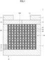
- FIG. 1 is a cross sectional view illustrating an example of the heat storage device according to a first embodiment.
- FIG. 2 is a perspective cross sectional view illustrating an example of a heat storage module according to the first embodiment.
- FIG. 3 is a diagram illustrating examples of a latent heat storage and an electric heater in the first embodiment.
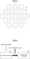
- FIG. 4 is a diagram illustrating an example of an arrangement of latent heat storages in the first embodiment.
- a heat storage device 1 includes a heat storage module 20, and a heat insulating member 10.
- heat storage modules 20 among a plurality of heat storage modules 20 are laminated on one another.
- the heat storage module 20 includes a ceramic part 22, a latent heat storage 24, and an electric heater 26.
- a plurality of closed spaces 28 are formed inside the ceramic part 22.
- the ceramic part 22 is integrally formed, for example.
- the ceramic part 22 does not have connecting portions connected to the closed spaces 28.
- the latent heat storage 24 is provided inside the closed space 28.
- the latent heat storage 24 is encapsulated inside the ceramic part 22. That is, the latent heat storage 24 is airtightly covered with the ceramic part 22 which is a continuous body.
- the ceramic part 22 has a function of preventing leakage of melted latent heat storage 24.
- the latent heat storage 24 has a columnar shape, such as a circular column shape or the like.
- the latent heat storage 24 is provided inside each of the closed spaces 28. That is, a plurality of latent heat storages 24 are provided inside the ceramic part 22. The plurality of latent heat storages 24 are arranged such that long axes of the latent heat storages 24 are parallel to one another. As illustrated in FIG. 4 , the plurality of latent heat storage 24 are densely arranged in a regular triangular lattice, for example.
- the latent heat storage 24 is formed of a metal, for example.
- the latent heat storage 24 includes one element selected from aluminum, copper, silicon, and boron, or an arbitrary combination of two or more elements selected from aluminum, copper, silicon, and boron, for example.
- a main component of the latent heat storage 24 may be aluminum.
- the latent heat storage 24 may include 99 mass% or more aluminum. That is, the latent heat storage 24 may be composed of aluminum with a purity of 99 mass% or more.
- the latent heat storage 24 may include one element selected from boron (B), aluminum (Al), bismuth (Bi), antimony (Sb), gallium (Ga), copper (Cu), iron (Fe), titanium (Ti), yttrium (Y), indium (In), zinc (Zn), and tin (Sn), or an arbitrary combination of two or more elements selected from B, Al, Bi, Sb, Ga, Cu, Fe, Ti, Y, In, Zn, and Sn, and amounting to less than 50 mass% in total.
- the main component of the latent heat storage 24 may be boron.
- the latent heat storage 24 may include 50 mass% or more boron.
- the latent heat storage 24 may be composed of boron with a purity of 50 mass% or more.
- the latent heat storage 24 includes 80 mass% or more boron, and is composed of boron with a purity of 80 mass% or more.
- the latent heat storage 24 includes 99 mass% or more boron, and is composed of boron with a purity of 99 mass% or more.
- the ceramic part 22 includes 96 mass% or more aluminum oxide (Al 2 O 3 ), for example. That is, the ceramic part 22 may be composed of aluminum oxide with a purity of 96 mass% or more.
- the ceramic part 22 includes 90 mass% or more aluminum oxide, or 90 mass% or more mullite (3Al 2 O 3 ⁇ 2SiO 2 ), or 95 mass% or more aluminum nitride (AlN), or 95 mass% or more mixture of aluminum nitride and boron nitride (BN), for example.
- the ceramic part 22 may further include a sintering aid or the like. Examples of the sintering aid include silicon, magnesium, calcium, or the like. Ceramic grains included in the ceramic part 22 preferably have a grain size of approximately 1 ⁇ m or less, and more preferably approximately 0.3 um or less, for example.
- the ceramic part 22 includes one material selected from mullite, aluminum oxide (Al 2 O 3 ), cordierite (2MgO ⁇ 2Al 2 O 3 ⁇ 5SiO 2 ), anorthite (CaAl 2 Si 2 O 8 ), sillimanite (Al 2 SiO 5 ), silicon nitride (Si 3 N 4 ), boron nitride, aluminum nitride, a composite material (composite ceramic) of aluminum nitride and boron nitride, silicon carbide (SiC), tungsten carbide (WC), boron carbide (B 4 C), molybdenum disilicide (MoSi 2 ), and tungsten disilicide (WSi 2 ), or an arbitrary combination of two or more materials selected from mullite, Al 2 O 3 , 2MgO ⁇ 2Al 2 O 3 ⁇ 5SiO 2 , CaAl 2 Si 2 O
- the ceramic part 22 may be composed of one material selected from mullite, aluminum oxide, cordierite, anorthite, sillimanite, silicon nitride, boron nitride, aluminum nitride, a composite material of aluminum nitride and boron nitride, silicon carbide, tungsten carbide, boron carbide, molybdenum disilicide, and tungsten disilicide, or an arbitrary combination of two or more materials selected from mullite, aluminum oxide, cordierite, anorthite, sillimanite, silicon nitride, boron nitride, aluminum nitride, a composite material of aluminum nitride and boron nitride, silicon carbide, tungsten carbide, boron carbide, molybdenum disilicide, and tungsten disilicide.
- the ceramic part 22 may include one material selected from boron nitride (BN), boron carbide (B 4 C), aluminum nitride (AlN), a composite material of aluminum nitride and boron nitride, silicon nitride (Si 3 N 4 ), and silicon carbide (SiC), or an arbitrary combination of two or more materials selected from BN, B 4 C, AlN, a composite material of aluminum nitride and boron nitride, Si 3 N 4 , and SiC.
- BN boron nitride
- B 4 C aluminum nitride
- AlN aluminum nitride
- Si 3 N 4 silicon carbide
- the ceramic part 22 may be composed of one of materials selected from boron nitride, boron carbide, aluminum nitride, a composite material (composite ceramic) of aluminum nitride and boron nitride, silicon nitride, and silicon carbide, or an arbitrary combination of two or more materials selected from boron nitride, boron carbide, aluminum nitride, a composite material (composite ceramic) of aluminum nitride and boron nitride, silicon nitride, and silicon carbide.
- the ceramic part 22 may include a boride.
- the ceramic part 22 may be composed of the boride.
- the boride is titanium boride (TiB 2 ), zirconium boride (ZrB 2 ), hafnium boride (HfB 2 ), vanadium boride (VB 2 ), niobium boride (NbB 2 ), tantalum boride (TaB 2 ), lanthanum boride (LaB 6 ), or an arbitrary combination thereof, for example.
- the electric heater 26 is provided inside the ceramic part 22.
- the electric heater 26 is provided between a surface of the ceramic part 22 and a surface of the latent heat storage 24.
- the electric heater 26 generates Joule heat when energized.
- the electric heater 26 has an approximately cylindrical shape around each latent heat storage 24.
- the electric heater 26 forms a spiral while alternately repeating clockwise and counterclockwise turns, for example, when viewed from a direction parallel to a major axis of the columnar latent heat storage 24.
- the electric heater 26 can heat the latent heat storage 24. From a viewpoint of reducing a heat loss, a distance between the electric heater 26 and the latent heat storage 24 is preferably small.
- the electric heater 26 includes tungsten, or molybdenum, or both tungsten and molybdenum.
- the electric heater 26 may include a mixture of tungsten and aluminum oxide, or a mixture of molybdenum and aluminum oxide.
- the electric heater 26 may further include one or more kinds of materials selected from silicon oxide, magnesium oxide, calcium carbonate, or the like.
- the electric heater 26 is an example of a heater.
- the heat insulating member 10 includes a main body 11, an openable and closable shutter 14, a first terminal 16, a second terminal 17, and a lid 18.
- the heat insulating member 10 covers a laminate of the plurality of heat storage modules 20.
- the heat insulating member 10 covers the ceramic part 22 of each heat storage module 20 of the plurality of heat storage modules 20.
- the laminate of the plurality of heat storage modules 20 is accommodated inside the main body 11, and the shutter 14 is provided so as to make contact with a surface 20A of one heat storage module 20.
- the surface 20A In a closed state of the shutter 14, the surface 20A is covered by the shutter 14, and in an open state of the shutter 14, a portion of the surface 20A is exposed from the shutter 14.
- the heat insulating member 10 is formed with an opening 12 communicating with the portion of the surface 20A exposed from the shutter 14 in the open state of the shutter 14.
- the same type of heat insulating material may be used for the main body 11 and the shutter 14, for example.
- a material that can suppress heat conduction and heat radiation, which are movement elements of heat, may be used for the main body 11 and the shutter 14.
- a porous material made of a solid material having a low heat conductivity is used.
- the size of pores is preferably such that effects of convection of gas can be reduced, and the pores are preferably filled with a gas having a low heat conductivity at a pressure that is low as much as possible.
- the heat insulating member 10 may be configured to hold the laminate of the plurality of heat storage modules 20 in a vacuum, and a reflecting layer may be provided at a boundary between the main body 11 and the shutter 14.
- the first terminal 16 and the second terminal 17 are provided inside a recess 13 that is formed in the main body 11.
- the first terminal 16 and the second terminal 17 are electrically connected to the electric heater 26.
- the first terminal 16 is a positive terminal
- the second terminal 17 is a negative terminal.
- the first terminal 16 and the second terminal 17 are an example of a power supply part.
- the lid 18 closes the recess 13.
- the lid 18 is composed of the same material as the main body 11 and the shutter 14, for example.
- the shutter 14 is closed, the lid 18 is removed, and a power supply cable is connected to the first terminal 16 and the second terminal 17. Further, electric power is supplied to the electric heater 26 via the power supply cable to cause the electric heater 26 to generate heat.
- the heat generated by the electric heater 26 is stored in the latent heat storage 24. That is, when the latent heat storage 24 is heated to a temperature higher than a solid-liquid phase change temperature (or liquidus temperature), latent heat generated by the phase change is stored in the latent heat storage 24.
- the power supply cable is disconnected from the first terminal 16 and the second terminal 17, and the lid 18 is attached to the recess 13. As a result, the heat stored in the latent heat storage 24 is held in the latent heat storage 24 by the ceramic part 22 and the heat insulating member 10.
- the shutter 14 is opened with the lid 18 attached.
- the heat stored in the latent heat storage 24 flows out through the open portion of the shutter 14 and the opening 12. This heat can be utilized for electric power generation or heating of heater or the like.
- the surplus electric power is supplied directly to the electric heater 26 as illustrated in FIG. 5 .
- the heat generated by the electric heater 26 is stored in the latent heat storage 24, but a heat transfer loss may occur during storage of the heat.
- the ceramic part 22 may be heated, or the heat insulating member 10 may be heated, and a portion of the heat may be released outside the heat storage device 1.
- the heat transfer loss occurs only at such locations.
- FIG. 5 is a diagram illustrating an example of the loss in the first embodiment.
- the heat transfer loss occurs when the air is heated, the heat transfer loss occurs during transport of the heated air, and the heat transfer loss also occurs when the latent heat storage is heated by using the heated air.
- the heat storage device 1 can reduce the energy loss until the heat storage using the electric power, when compared to a heat storage device in which the heat storage is heated by using the heated air.
- the latent heat storage 24 can store a large amount of heat when compared to a sensible heat storage.
- aluminum can store heat that is approximately two times an amount storable by a sensible heat storage per unit mass, although the amount storable depends on a specific heat of the sensible heat material used.
- a latent heat of fusion of silicon is four times or more the latent heat of fusion of aluminum
- the latent heat of fusion of boron is eleven times or more the latent heat of fusion of aluminum, per unit mass, and thus, a large amount of heat can be stored thereby. Accordingly, by using the latent heat storage 24, it is possible to obtain an energy storage density higher than that of a lithium ion battery. For this reason, the heat storage device 1 can store a large amount of energy with a small size.
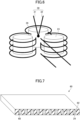
- FIG. 6 is a diagram illustrating examples of the latent heat storage, the electric heater, and a thermocouple according to the first modification of the first embodiment.
- thermocouple 30 is provided inside the heat storage module 20, as illustrated in FIG. 6 .
- the thermocouple 30 includes a first conductor 31 and a second conductor 32.
- One end of the first conductor 31 is connected to one end of the second conductor 32.
- the first conductor 31 and the second conductor 32 have mutually different thermoelectric powers.
- the first conductor 31 and the second conductor 32 include a tungsten-rhenium alloy, the first conductor 31 is composed of 5 mass% rhenium and 95 mass% tungsten, and the second conductor 32 is composed of 26 mass% rhenium and 74 mass% tungsten.
- the first modification can also obtain effects similar to those obtainable by the first embodiment.
- the thermocouple 30 is provided, it is possible to easily grasp the state of the latent heat storage 24. For example, in the heat storage process, the temperature indicated by the thermocouple 30 increases with the lapse of time while the latent heat storage 24 is solid, whereas the temperature indicated by the thermocouple 30 is stable while the phase of the latent heat storage 24 changes from solid to liquid. Thereafter, when the phase change is completed, the temperature indicated by the thermocouple 30 rises again with the lapse of time. Accordingly, it is possible to easily grasp whether the phase change has started, whether the phase change is continuing, or whether the phase change is completed.
- the latent heat storage 24 after the completion of the phase change to liquid is further heated, the latent heat cannot be stored, and the input energy may be wasted.
- the completion of the phase change can be detected using the thermocouple 30, after the phase change is completed, it is possible to avoid wasting the energy by storing the heat in another heat storage device 1.
- FIG. 7 is a perspective cross sectional view illustrating an example of the heat storage module according to the second modification of the first embodiment.
- the heat storage device includes a heat storage module 60 in place of the heat storage module 20.
- the heat storage module 60 includes a ceramic part 62, and the latent heat storage 24.
- a plurality of closed spaces 68 are formed inside the ceramic part 62.
- the ceramic part 62 has the same configuration as the ceramic part 22, but a material used for the ceramic part 62 is different from the material used for the ceramic part 22.
- Examples of the material used for the ceramic part 62 include carbides.
- the carbides include silicon carbide, tungsten carbide, and boron carbide. Silicon carbide, tungsten carbide, and boron carbide have conductivity, although the conductivity depends on a carbon content. Silicon carbide, tungsten carbide, and boron carbide are materials that generate heat when energized, and silicon carbide, tungsten carbide, and boron carbide can be used as a heater.
- the ceramic part 62 includes silicon carbide, tungsten carbide, or boron carbide, the ceramic part 62 has functions of protecting and heating the latent heat storage 24, and thus, a higher heat storage density can easily be achieved.
- Examples of the material used for the ceramic part 62 include silicides.
- the silicides include molybdenum disilicide (MoSi 2 ) and tungsten disilicide (WSi 2 ). Molybdenum disilicide and tungsten disilicide are materials that generate heat when energized.
- Molybdenum disilicide and tungsten disilicide are materials that generate heat when energized.
- the ceramic part 62 includes molybdenum disilicide or tungsten disilicide, the ceramic part 62 has the functions of protecting and heating the latent heat storage 24, and thus, a higher heat storage density can easily be achieved.
- a dense oxide film of silicon dioxide (SiO 2 ) is formed on surfaces of the molybdenum disilicide and the tungsten disilicide, and oxidation of the inside of the molybdenum disilicide and the tungsten disilicide is prevented. Accordingly, the ceramic part 62 including the molybdenum disilicide or the tungsten disilicide is chemically stable even in the atmosphere.
- the electric power is supplied from the first terminal 16 and the second terminal 17 to the ceramic part 22.
- the second modification can also obtain effects similar to those obtainable by the first embodiment.
- FIG. 8 is a cross sectional view illustrating an example of the power generator according to the second embodiment.
- FIG. 9 is a diagram illustrating an example of the loss in the second embodiment.
- a power generator 2 includes the heat storage device 1, and a Stirling engine 40.
- the Stirling engine 40 includes a high temperature side cylinder 42 having a displacer piston 44, and a low temperature side cylinder (not illustrated) .
- the shutter 14 of the heat storage device 1 is open, and the high temperature side cylinder 42 makes contact with the surface 20A of the heat storage module 20 through the opening 12 and the open portion of the shutter 14.
- the heat storage device 1 stores heat as in the first embodiment.
- a gas inside the high temperature side cylinder 42 absorbs the heat stored in the latent heat storage 24 through the open shutter 14. Further, the gas inside the high temperature side cylinder 42 thermally expands. As a result, the Stirling engine 40 perform the work to generate electric power.
- the power generator 2 includes the heat storage device 1, and can thus reduce the energy loss until the heat storage using the electric power. In addition, it is possible to also reduce the energy loss even when the electric power is generated by using the heat stored in the heat storage device 1. That is, as illustrated in FIG. 9 , a heat transfer loss may occur when the heat stored in the latent heat storage 24 is transferred to the Stirling engine 40, but the heat transfer loss occurs only at this location.
- the Stirling engine has a higher energy efficiency than an internal combustion engine and a steam engine, and the efficiency of the Stirling engine becomes closer to an efficiency of a Carnot cycle as a temperature difference between the high temperature side cylinder and the low temperature side cylinder increases.
- the power generator 2 can reduce the energy loss between the heat storage and the electric power generation, when compared to the power generator that generates the steam by using the heated air and generates the electric power by rotating the turbine by the steam. Accordingly, even if the power generator 2 is small, it is possible to obtain a high energy efficiency with a small heat loss, and for example, the power generator 2 is suitable for utilizing the surplus power of a small-scale distributed power generation facility in a solar power generation facility, a wind power generation facility, or the like.
- the high temperature side cylinder 42 is configured to be attachable to and detachable from the heat storage device 1, it is possible to prevent heat radiation through the high temperature side cylinder 42 by detaching and removing the high temperature side cylinder 42 when storing the heat.
- FIG. 10 is a cross sectional view illustrating an example of the heat generator according to the third embodiment.
- a heat generator 3 includes the heat storage device 1, and a heat exchanger 50.
- the heat exchanger 50 includes a housing 58, an internal flow path 52, a first external flow path 54, and a second external flow path 56.
- the internal flow path 52 is provided inside the housing 58, and the first external flow path 54 and the second external flow path 56 are provided outside the housing 58.
- the internal flow path 52 has an inlet end and an outlet end, the first external flow path 54 is connected to the inlet end, and the second external flow path 56 is connected to the outlet end.
- a heating medium flows through the internal flow path 52, the first external flow path 54, and the second external flow path 56.
- the shutter 14 of the heat storage device 1 is open, and the heat exchanger 50 makes contact with the surface 20A of the heat storage module 20 through the opening 12 and the open portion of the shutter 14.
- the heat storage device 1 stores the heat as in the first embodiment.
- the heating medium inside the internal flow path 52 absorbs the heat stored in the latent heat storage 24 through the open shutter 14.
- the heat generator 3 according to the third embodiment includes the heat storage device 1, and thus, it is possible to reduce the energy loss until the heat storage using the electric power. Further, it is possible to reduce the energy loss even when the heat stored in the heat storage device 1 is used to generate the heat. That is, the heating medium flows from the first external flow path 54 into the internal flow path 52, and the heating medium is heated by the heat storage module 20. Then, the heated heating medium flows out from the internal flow path 52 to the second external flow path 56. A heat transfer loss may occur when the heat stored in the latent heat storage 24 is transferred to the heating medium, but the heat transfer loss occurs only at this location.
- the heat exchanger 50 is configured to be attachable to and detachable from the heat storage device 1, the heat exchanger 50 can be detached and removed to prevent the heat radiation through the heat exchanger 50 when storing the heat.
- the heat generator 3 can be used for the heater or the like for heating a space inside a house, for example.
Landscapes
- Engineering & Computer Science (AREA)
- Mechanical Engineering (AREA)
- General Engineering & Computer Science (AREA)
- Physics & Mathematics (AREA)
- Thermal Sciences (AREA)
- Ceramic Engineering (AREA)
- Chemical & Material Sciences (AREA)
- Combustion & Propulsion (AREA)
- Battery Mounting, Suspending (AREA)
- Secondary Cells (AREA)
Abstract
Description
- Certain aspects of the embodiments discussed herein are related to heat storage devices, power generators, and heat generators.
- Conventionally, a proposed latent heat storage uses an Al-Si alloy or the like as a phase change material (PCM), and a protective layer surrounding the PCM.
- Further, a proposed heat storage device heats a heat storage using heated air. In the heat storage using the heat storage device, the air is heated using electric power, and the heat storage is heated using the heated air.
- Related art include
Japanese Laid-Open Patent Publication No. 2021-031507 Japanese Laid-Open Patent Publication No. 2015-048393 - In the conventional heat storage device, an energy loss is large until the heat storage using the electric power.
- Accordingly, it is an object in one aspect of the embodiments to provide a heat storage device, a power generator, and a heat generator which can reduce an energy loss.
- According to one aspect of the embodiments, a heat storage device includes a ceramic part having a closed space therein; a latent heat storage provided inside the closed space; an electric heater provided inside the ceramic part and configured to heat the latent heat storage; a heat insulating member covering the ceramic part; and a power supply part configured to supply electric power to the electric heater.
- According to another aspect of the embodiments, a heat storage device includes a ceramic part having a closed space therein and including a material that generates heat when energized; a latent heat storage provided inside the closed space; a heat insulating member covering the ceramic part; and a power supply part configured to supply electric power to the ceramic part.
- The object and advantages of the embodiments will be realized and attained by means of the elements and combinations particularly pointed out in the claims.
- It is to be understood that both the foregoing general description and the following detailed description are exemplary and explanatory and not restrictive of the invention, as claimed.
-
-
FIG. 1 is a cross sectional view illustrating an example of a heat storage device according to a first embodiment; -
FIG. 2 is a perspective sectional view illustrating an example of a heat storage module according to the first embodiment; -
FIG. 3 is a diagram illustrating examples of a latent heat storage and an electric heater in the first embodiment; -
FIG. 4 is a diagram illustrating an example of an arrangement of latent heat storages in the first embodiment; -
FIG. 5 is a diagram illustrating an example of a loss in the first embodiment; -
FIG. 6 is a diagram illustrating an example of the latent heat storage, the electric heater, and a thermocouple according to a first modification of the first embodiment; -
FIG. 7 is a perspective sectional view illustrating an example of the heat storage module according to a second modification of the first embodiment; -
FIG. 8 is a cross sectional view illustrating an example of a power generator according to the second embodiment. -
FIG. 9 is a diagram illustrating an example of the loss in the second embodiment; and -
FIG. 10 is a cross sectional view illustrating an example of the heat generator according to a third embodiment. - Hereinafter, embodiments will be described in detail with reference to the accompanying drawings. In the specification and the drawings, constituent elements or components having substantially the same functional configuration are designated by the same reference numerals, and a redundant description thereof may be omitted.
- First, a first embodiment will be described. The first embodiment relates to a heat storage device.
FIG. 1 is a cross sectional view illustrating an example of the heat storage device according to a first embodiment.FIG. 2 is a perspective cross sectional view illustrating an example of a heat storage module according to the first embodiment.FIG. 3 is a diagram illustrating examples of a latent heat storage and an electric heater in the first embodiment.FIG. 4 is a diagram illustrating an example of an arrangement of latent heat storages in the first embodiment. - As illustrated in
FIG. 1 , aheat storage device 1 according to the first embodiment includes aheat storage module 20, and aheat insulating member 10. For example,heat storage modules 20 among a plurality ofheat storage modules 20 are laminated on one another. - The
heat storage module 20 includes aceramic part 22, alatent heat storage 24, and anelectric heater 26. A plurality of closedspaces 28 are formed inside theceramic part 22. Theceramic part 22 is integrally formed, for example. For example, theceramic part 22 does not have connecting portions connected to the closedspaces 28. Thelatent heat storage 24 is provided inside the closedspace 28. In other words, thelatent heat storage 24 is encapsulated inside theceramic part 22. That is, thelatent heat storage 24 is airtightly covered with theceramic part 22 which is a continuous body. Theceramic part 22 has a function of preventing leakage of meltedlatent heat storage 24. Thelatent heat storage 24 has a columnar shape, such as a circular column shape or the like. Thelatent heat storage 24 is provided inside each of the closedspaces 28. That is, a plurality oflatent heat storages 24 are provided inside theceramic part 22. The plurality oflatent heat storages 24 are arranged such that long axes of thelatent heat storages 24 are parallel to one another. As illustrated inFIG. 4 , the plurality oflatent heat storage 24 are densely arranged in a regular triangular lattice, for example. - The
latent heat storage 24 is formed of a metal, for example. Thelatent heat storage 24 includes one element selected from aluminum, copper, silicon, and boron, or an arbitrary combination of two or more elements selected from aluminum, copper, silicon, and boron, for example. - A main component of the
latent heat storage 24 may be aluminum. Thelatent heat storage 24 may include 99 mass% or more aluminum. That is, thelatent heat storage 24 may be composed of aluminum with a purity of 99 mass% or more. - The main component of the
latent heat storage 24 may be copper. Thelatent heat storage 24 may include 99 mass% or more copper. That is, thelatent heat storage 24 may be composed of copper with a purity of 99 mass% or more. - The main component of the
latent heat storage 24 may be silicon. Thelatent heat storage 24 may include 50 mass% or more silicon. Thelatent heat storage 24 may be composed of silicon with a purity of 50 mass% or more. Preferably, thelatent heat storage 24 includes 99 mass% or more silicon, and is composed of silicon with a purity of 99 mass% or more. Thelatent heat storage 24 may include one element selected from boron (B), aluminum (Al), bismuth (Bi), antimony (Sb), gallium (Ga), copper (Cu), iron (Fe), titanium (Ti), yttrium (Y), indium (In), zinc (Zn), and tin (Sn), or an arbitrary combination of two or more elements selected from B, Al, Bi, Sb, Ga, Cu, Fe, Ti, Y, In, Zn, and Sn, and amounting to less than 50 mass% in total. - The main component of the
latent heat storage 24 may be boron. Thelatent heat storage 24 may include 50 mass% or more boron. Thelatent heat storage 24 may be composed of boron with a purity of 50 mass% or more. Preferably, thelatent heat storage 24 includes 80 mass% or more boron, and is composed of boron with a purity of 80 mass% or more. More preferably, thelatent heat storage 24 includes 99 mass% or more boron, and is composed of boron with a purity of 99 mass% or more. Thelatent heat storage 24 may include one element selected from silicon (Si), aluminum (Al), iron (Fe), copper (Cu), and cobalt (Co), or an arbitrary combination of two or more elements selected from Si, Al, Fe, Cu, and Co, and amounting to less than 20 mass% in total. - In the case where the main component of the
latent heat storage 24 is aluminum, theceramic part 22 includes 96 mass% or more aluminum oxide (Al2O3), for example. That is, theceramic part 22 may be composed of aluminum oxide with a purity of 96 mass% or more. - In the case where the main component of the
latent heat storage 24 is copper, theceramic part 22 includes 90 mass% or more aluminum oxide, or 90 mass% or more mullite (3Al2O3·2SiO2), or 95 mass% or more aluminum nitride (AlN), or 95 mass% or more mixture of aluminum nitride and boron nitride (BN), for example. Theceramic part 22 may further include a sintering aid or the like. Examples of the sintering aid include silicon, magnesium, calcium, or the like. Ceramic grains included in theceramic part 22 preferably have a grain size of approximately 1 µm or less, and more preferably approximately 0.3 um or less, for example. - In the case where the main component of the
latent heat storage 24 is silicon, theceramic part 22 includes one material selected from mullite, aluminum oxide (Al2O3), cordierite (2MgO·2Al2O3·5SiO2), anorthite (CaAl2Si2O8), sillimanite (Al2SiO5), silicon nitride (Si3N4), boron nitride, aluminum nitride, a composite material (composite ceramic) of aluminum nitride and boron nitride, silicon carbide (SiC), tungsten carbide (WC), boron carbide (B4C), molybdenum disilicide (MoSi2), and tungsten disilicide (WSi2), or an arbitrary combination of two or more materials selected from mullite, Al2O3, 2MgO·2Al2O3·5SiO2, CaAl2Si2O8, Al2SiO5, Si3N4, boron nitride, aluminum nitride, a composite material (composite ceramic) of aluminum nitride and boron nitride, silicon carbide, tungsten carbide, boron carbide, molybdenum disilicide, and tungsten disilicide, for example. Theceramic part 22 may be composed of one material selected from mullite, aluminum oxide, cordierite, anorthite, sillimanite, silicon nitride, boron nitride, aluminum nitride, a composite material of aluminum nitride and boron nitride, silicon carbide, tungsten carbide, boron carbide, molybdenum disilicide, and tungsten disilicide, or an arbitrary combination of two or more materials selected from mullite, aluminum oxide, cordierite, anorthite, sillimanite, silicon nitride, boron nitride, aluminum nitride, a composite material of aluminum nitride and boron nitride, silicon carbide, tungsten carbide, boron carbide, molybdenum disilicide, and tungsten disilicide. - In the case where the main component of the
latent heat storage 24 is boron, theceramic part 22 may include one material selected from boron nitride (BN), boron carbide (B4C), aluminum nitride (AlN), a composite material of aluminum nitride and boron nitride, silicon nitride (Si3N4), and silicon carbide (SiC), or an arbitrary combination of two or more materials selected from BN, B4C, AlN, a composite material of aluminum nitride and boron nitride, Si3N4, and SiC. Theceramic part 22 may be composed of one of materials selected from boron nitride, boron carbide, aluminum nitride, a composite material (composite ceramic) of aluminum nitride and boron nitride, silicon nitride, and silicon carbide, or an arbitrary combination of two or more materials selected from boron nitride, boron carbide, aluminum nitride, a composite material (composite ceramic) of aluminum nitride and boron nitride, silicon nitride, and silicon carbide. - In the case where the main component of the
latent heat storage 24 is boron, theceramic part 22 may include a boride. Theceramic part 22 may be composed of the boride. The boride is titanium boride (TiB2), zirconium boride (ZrB2), hafnium boride (HfB2), vanadium boride (VB2), niobium boride (NbB2), tantalum boride (TaB2), lanthanum boride (LaB6), or an arbitrary combination thereof, for example. - The
electric heater 26 is provided inside theceramic part 22. Theelectric heater 26 is provided between a surface of theceramic part 22 and a surface of thelatent heat storage 24. Theelectric heater 26 generates Joule heat when energized. Theelectric heater 26 has an approximately cylindrical shape around eachlatent heat storage 24. Theelectric heater 26 forms a spiral while alternately repeating clockwise and counterclockwise turns, for example, when viewed from a direction parallel to a major axis of the columnarlatent heat storage 24. Theelectric heater 26 can heat thelatent heat storage 24. From a viewpoint of reducing a heat loss, a distance between theelectric heater 26 and thelatent heat storage 24 is preferably small. Theelectric heater 26 includes tungsten, or molybdenum, or both tungsten and molybdenum. Theelectric heater 26 may include a mixture of tungsten and aluminum oxide, or a mixture of molybdenum and aluminum oxide. In this case, theelectric heater 26 may further include one or more kinds of materials selected from silicon oxide, magnesium oxide, calcium carbonate, or the like. Theelectric heater 26 is an example of a heater. - The
heat insulating member 10 includes amain body 11, an openable andclosable shutter 14, afirst terminal 16, asecond terminal 17, and alid 18. Theheat insulating member 10 covers a laminate of the plurality ofheat storage modules 20. Theheat insulating member 10 covers theceramic part 22 of eachheat storage module 20 of the plurality ofheat storage modules 20. - The laminate of the plurality of
heat storage modules 20 is accommodated inside themain body 11, and theshutter 14 is provided so as to make contact with asurface 20A of oneheat storage module 20. In a closed state of theshutter 14, thesurface 20A is covered by theshutter 14, and in an open state of theshutter 14, a portion of thesurface 20A is exposed from theshutter 14. Theheat insulating member 10 is formed with anopening 12 communicating with the portion of thesurface 20A exposed from theshutter 14 in the open state of theshutter 14. - The same type of heat insulating material may be used for the
main body 11 and theshutter 14, for example. A material that can suppress heat conduction and heat radiation, which are movement elements of heat, may be used for themain body 11 and theshutter 14. For example, a porous material made of a solid material having a low heat conductivity is used. The size of pores is preferably such that effects of convection of gas can be reduced, and the pores are preferably filled with a gas having a low heat conductivity at a pressure that is low as much as possible. Theheat insulating member 10 may be configured to hold the laminate of the plurality ofheat storage modules 20 in a vacuum, and a reflecting layer may be provided at a boundary between themain body 11 and theshutter 14. - The
first terminal 16 and thesecond terminal 17 are provided inside arecess 13 that is formed in themain body 11. Thefirst terminal 16 and thesecond terminal 17 are electrically connected to theelectric heater 26. For example, thefirst terminal 16 is a positive terminal, and thesecond terminal 17 is a negative terminal. Thefirst terminal 16 and thesecond terminal 17 are an example of a power supply part. - The
lid 18 closes therecess 13. Thelid 18 is composed of the same material as themain body 11 and theshutter 14, for example. - In the case where heat is stored in the
heat storage device 1, theshutter 14 is closed, thelid 18 is removed, and a power supply cable is connected to thefirst terminal 16 and thesecond terminal 17. Further, electric power is supplied to theelectric heater 26 via the power supply cable to cause theelectric heater 26 to generate heat. The heat generated by theelectric heater 26 is stored in thelatent heat storage 24. That is, when thelatent heat storage 24 is heated to a temperature higher than a solid-liquid phase change temperature (or liquidus temperature), latent heat generated by the phase change is stored in thelatent heat storage 24. After supplying the electric power, the power supply cable is disconnected from thefirst terminal 16 and thesecond terminal 17, and thelid 18 is attached to therecess 13. As a result, the heat stored in thelatent heat storage 24 is held in thelatent heat storage 24 by theceramic part 22 and theheat insulating member 10. - Moreover, in the case where the heat stored in the
heat storage device 1 is to be used, theshutter 14 is opened with thelid 18 attached. As a result, the heat stored in thelatent heat storage 24 flows out through the open portion of theshutter 14 and theopening 12. This heat can be utilized for electric power generation or heating of heater or the like. - According to the first embodiment, it is possible to reduce the energy loss until the heat storage using the electric power. For example, in a case where heat is stored using surplus electric power, the surplus electric power is supplied directly to the
electric heater 26 as illustrated inFIG. 5 . The heat generated by theelectric heater 26 is stored in thelatent heat storage 24, but a heat transfer loss may occur during storage of the heat. For example, theceramic part 22 may be heated, or theheat insulating member 10 may be heated, and a portion of the heat may be released outside theheat storage device 1. However, the heat transfer loss occurs only at such locations.FIG. 5 is a diagram illustrating an example of the loss in the first embodiment. - On the other hand, in a case where air is heated by using the surplus electric power and the latent heat storage is heated by using the heated air, the heat transfer loss occurs when the air is heated, the heat transfer loss occurs during transport of the heated air, and the heat transfer loss also occurs when the latent heat storage is heated by using the heated air.
- As described above, the
heat storage device 1 according to the first embodiment can reduce the energy loss until the heat storage using the electric power, when compared to a heat storage device in which the heat storage is heated by using the heated air. - In addition, the
latent heat storage 24 can store a large amount of heat when compared to a sensible heat storage. For example, aluminum can store heat that is approximately two times an amount storable by a sensible heat storage per unit mass, although the amount storable depends on a specific heat of the sensible heat material used. Moreover, a latent heat of fusion of silicon is four times or more the latent heat of fusion of aluminum, and the latent heat of fusion of boron is eleven times or more the latent heat of fusion of aluminum, per unit mass, and thus, a large amount of heat can be stored thereby. Accordingly, by using thelatent heat storage 24, it is possible to obtain an energy storage density higher than that of a lithium ion battery. For this reason, theheat storage device 1 can store a large amount of energy with a small size. - A first modification of the first embodiment will be described. The first modification differs from the first embodiment in that a thermocouple is provided.
FIG. 6 is a diagram illustrating examples of the latent heat storage, the electric heater, and a thermocouple according to the first modification of the first embodiment. - In the first modification, a
thermocouple 30 is provided inside theheat storage module 20, as illustrated inFIG. 6 . Thethermocouple 30 includes afirst conductor 31 and asecond conductor 32. One end of thefirst conductor 31 is connected to one end of thesecond conductor 32. Thefirst conductor 31 and thesecond conductor 32 have mutually different thermoelectric powers. For example, thefirst conductor 31 and thesecond conductor 32 include a tungsten-rhenium alloy, thefirst conductor 31 is composed of 5 mass% rhenium and 95 mass% tungsten, and thesecond conductor 32 is composed of 26 mass% rhenium and 74 mass% tungsten. - Otherwise, the configuration of the first modification is the same as that of the first embodiment.
- The first modification can also obtain effects similar to those obtainable by the first embodiment. Further, because the
thermocouple 30 is provided, it is possible to easily grasp the state of thelatent heat storage 24. For example, in the heat storage process, the temperature indicated by thethermocouple 30 increases with the lapse of time while thelatent heat storage 24 is solid, whereas the temperature indicated by thethermocouple 30 is stable while the phase of thelatent heat storage 24 changes from solid to liquid. Thereafter, when the phase change is completed, the temperature indicated by thethermocouple 30 rises again with the lapse of time. Accordingly, it is possible to easily grasp whether the phase change has started, whether the phase change is continuing, or whether the phase change is completed. - In the heat storage device, even if the
latent heat storage 24 after the completion of the phase change to liquid is further heated, the latent heat cannot be stored, and the input energy may be wasted. In contrast, in the present embodiment, because the completion of the phase change can be detected using thethermocouple 30, after the phase change is completed, it is possible to avoid wasting the energy by storing the heat in anotherheat storage device 1. - Next, a second modification of the first embodiment will be described. The second modification differs from the first embodiment in that the heat storage module has a configuration different from that of the first embodiment.
FIG. 7 is a perspective cross sectional view illustrating an example of the heat storage module according to the second modification of the first embodiment. - The heat storage device according to the second modification includes a
heat storage module 60 in place of theheat storage module 20. Theheat storage module 60 includes aceramic part 62, and thelatent heat storage 24. A plurality ofclosed spaces 68 are formed inside theceramic part 62. Theceramic part 62 has the same configuration as theceramic part 22, but a material used for theceramic part 62 is different from the material used for theceramic part 22. - Examples of the material used for the
ceramic part 62 include carbides. The carbides include silicon carbide, tungsten carbide, and boron carbide. Silicon carbide, tungsten carbide, and boron carbide have conductivity, although the conductivity depends on a carbon content. Silicon carbide, tungsten carbide, and boron carbide are materials that generate heat when energized, and silicon carbide, tungsten carbide, and boron carbide can be used as a heater. In the case where theceramic part 62 includes silicon carbide, tungsten carbide, or boron carbide, theceramic part 62 has functions of protecting and heating thelatent heat storage 24, and thus, a higher heat storage density can easily be achieved. - Examples of the material used for the
ceramic part 62 include silicides. The silicides include molybdenum disilicide (MoSi2) and tungsten disilicide (WSi2). Molybdenum disilicide and tungsten disilicide are materials that generate heat when energized. When theceramic part 62 includes molybdenum disilicide or tungsten disilicide, theceramic part 62 has the functions of protecting and heating thelatent heat storage 24, and thus, a higher heat storage density can easily be achieved. Further, in atmosphere, a dense oxide film of silicon dioxide (SiO2) is formed on surfaces of the molybdenum disilicide and the tungsten disilicide, and oxidation of the inside of the molybdenum disilicide and the tungsten disilicide is prevented. Accordingly, theceramic part 62 including the molybdenum disilicide or the tungsten disilicide is chemically stable even in the atmosphere. - In the second modification, the electric power is supplied from the
first terminal 16 and thesecond terminal 17 to theceramic part 22. - Otherwise, the configuration of the second modification is the same as that of the first embodiment.
- The second modification can also obtain effects similar to those obtainable by the first embodiment.
- Next, a second embodiment will be described. The second embodiment relates to a power generator including the
heat storage device 1.FIG. 8 is a cross sectional view illustrating an example of the power generator according to the second embodiment.FIG. 9 is a diagram illustrating an example of the loss in the second embodiment. - As illustrated in
FIG. 8 andFIG. 9 , apower generator 2 according to the second embodiment includes theheat storage device 1, and aStirling engine 40. TheStirling engine 40 includes a hightemperature side cylinder 42 having adisplacer piston 44, and a low temperature side cylinder (not illustrated) . Theshutter 14 of theheat storage device 1 is open, and the hightemperature side cylinder 42 makes contact with thesurface 20A of theheat storage module 20 through theopening 12 and the open portion of theshutter 14. - In the
power generator 2 according to the second embodiment, theheat storage device 1 stores heat as in the first embodiment. A gas inside the hightemperature side cylinder 42 absorbs the heat stored in thelatent heat storage 24 through theopen shutter 14. Further, the gas inside the hightemperature side cylinder 42 thermally expands. As a result, theStirling engine 40 perform the work to generate electric power. - The
power generator 2 according to the second embodiment includes theheat storage device 1, and can thus reduce the energy loss until the heat storage using the electric power. In addition, it is possible to also reduce the energy loss even when the electric power is generated by using the heat stored in theheat storage device 1. That is, as illustrated inFIG. 9 , a heat transfer loss may occur when the heat stored in thelatent heat storage 24 is transferred to theStirling engine 40, but the heat transfer loss occurs only at this location. In general, the Stirling engine has a higher energy efficiency than an internal combustion engine and a steam engine, and the efficiency of the Stirling engine becomes closer to an efficiency of a Carnot cycle as a temperature difference between the high temperature side cylinder and the low temperature side cylinder increases. - In contrast, in a case where the air is heated by the heat stored in the
latent heat storage 24, the steam is generated by using the heated air, and a turbine is rotated to generate the electric power, the heat transfer loss occurs when the air is heated, the heat transfer loss occurs during the transport of the heated air, and the heat transfer loss also occurs when the steam is generated by using the heated air. - As described above, the
power generator 2 according to the second embodiment can reduce the energy loss between the heat storage and the electric power generation, when compared to the power generator that generates the steam by using the heated air and generates the electric power by rotating the turbine by the steam. Accordingly, even if thepower generator 2 is small, it is possible to obtain a high energy efficiency with a small heat loss, and for example, thepower generator 2 is suitable for utilizing the surplus power of a small-scale distributed power generation facility in a solar power generation facility, a wind power generation facility, or the like. - Moreover, because the high
temperature side cylinder 42 is configured to be attachable to and detachable from theheat storage device 1, it is possible to prevent heat radiation through the hightemperature side cylinder 42 by detaching and removing the hightemperature side cylinder 42 when storing the heat. - Next, a third embodiment will be described. The third embodiment relates to a heat generator including the
heat storage device 1.FIG. 10 is a cross sectional view illustrating an example of the heat generator according to the third embodiment. - As illustrated in
FIG. 10 , aheat generator 3 according to the third embodiment includes theheat storage device 1, and aheat exchanger 50. Theheat exchanger 50 includes ahousing 58, aninternal flow path 52, a firstexternal flow path 54, and a secondexternal flow path 56. Theinternal flow path 52 is provided inside thehousing 58, and the firstexternal flow path 54 and the secondexternal flow path 56 are provided outside thehousing 58. Theinternal flow path 52 has an inlet end and an outlet end, the firstexternal flow path 54 is connected to the inlet end, and the secondexternal flow path 56 is connected to the outlet end. A heating medium flows through theinternal flow path 52, the firstexternal flow path 54, and the secondexternal flow path 56. - The
shutter 14 of theheat storage device 1 is open, and theheat exchanger 50 makes contact with thesurface 20A of theheat storage module 20 through theopening 12 and the open portion of theshutter 14. - In the
heat generator 3 according to the third embodiment, theheat storage device 1 stores the heat as in the first embodiment. The heating medium inside theinternal flow path 52 absorbs the heat stored in thelatent heat storage 24 through theopen shutter 14. - The
heat generator 3 according to the third embodiment includes theheat storage device 1, and thus, it is possible to reduce the energy loss until the heat storage using the electric power. Further, it is possible to reduce the energy loss even when the heat stored in theheat storage device 1 is used to generate the heat. That is, the heating medium flows from the firstexternal flow path 54 into theinternal flow path 52, and the heating medium is heated by theheat storage module 20. Then, the heated heating medium flows out from theinternal flow path 52 to the secondexternal flow path 56. A heat transfer loss may occur when the heat stored in thelatent heat storage 24 is transferred to the heating medium, but the heat transfer loss occurs only at this location. - Moreover, because the
heat exchanger 50 is configured to be attachable to and detachable from theheat storage device 1, theheat exchanger 50 can be detached and removed to prevent the heat radiation through theheat exchanger 50 when storing the heat. - The
heat generator 3 can be used for the heater or the like for heating a space inside a house, for example. - According to the disclosed technique, it is possible to reduce an energy loss.
- Although the embodiments are numbered with, for example, "first," "second," or "third," the ordinal numbers do not imply priorities of the embodiments. Many other variations and modifications will be apparent to those skilled in the art.
- All examples and conditional language recited herein are intended for pedagogical purposes to aid the reader in understanding the invention and the concepts contributed by the inventor to furthering the art, and are to be construed as being without limitation to such specifically recited examples and conditions, nor does the organization of such examples in the specification relate to a showing of the superiority and inferiority of the invention. Although the embodiments of the present invention have been described in detail, it should be understood that the various changes, substitutions, and alterations could be made hereto without departing from the spirit and scope of the invention.
Claims (11)
- A heat storage device (1) comprising:a ceramic part (22, 62) having a closed space therein;a latent heat storage (24) provided inside the closed space;an electric heater (26) provided inside the ceramic part (22, 62) and configured to heat the latent heat storage (24) ;a heat insulating member (10) covering the ceramic part (22, 62); anda power supply part (16, 17) configured to supply electric power to the electric heater (26).
- A heat storage device (1) comprising:a ceramic part (22, 62) having a closed space therein and including a material that generates heat when energized;a latent heat storage (24) provided inside the closed space;a heat insulating member (10) covering the ceramic part (22, 62); anda power supply part (16, 17) configured to supply electric power to the ceramic part (22, 62).
- The heat storage device (1) as claimed in claim 1 or 2, wherein the latent heat storage (24) includes one element selected from a group consisting of aluminum, copper, silicon, and boron, or an arbitrary combination of two or more elements selected from the group.
- The heat storage device (1) as claimed in claim 1 or 2, further comprising:
a thermocouple (30) configured to generate electric power by a temperature change of the latent heat storage (24) . - A power generator (2) comprising:the heat storage device (1) as claimed in claim 1 or 2; anda heat engine (40) configured to generate electric power using heat stored in the latent heat storage (24).
- The power generator (2) as claimed in claim 5, wherein:the heat engine (40) has a cylinder (42), anda gas inside the cylinder (42) absorbs the heat stored in the latent heat storage (24) and thermally expands.
- The power generator (2) as claimed in claim 6, wherein:the heat insulating member (10) is configured to be openable and closable, andthe gas inside the cylinder (42) absorbs the heat stored in the latent heat storage (24) through an open portion of the heat insulating member (10).
- The power generator (2) as claimed in claim 6, wherein the cylinder (42) is attachable to and detachable from the heat storage device (1).
- A heat generator (3) comprising:the heat storage device (1) as claimed in claim 1 or 2; anda heat exchanger (50) including a flow path (52, 54, 56) and configured to transfer heat stored in the latent heat storage (24) to a heating medium in the flow path (52, 54, 56) .
- The heat generator (3) as claimed in claim 9, wherein:the heat insulating member (10) is configured to be openable and closable, andthe heating medium in the flow path (52, 54, 56) absorbs the heat stored in the latent heat storage (24) through an open portion of the heat insulating member (10).
- The heat generator (3) as claimed in claim 9, wherein the heat exchanger (50) is attachable to and detachable from the heat storage device (1).
Applications Claiming Priority (1)
| Application Number | Priority Date | Filing Date | Title |
|---|---|---|---|
| JP2023137853A JP2025032536A (en) | 2023-08-28 | 2023-08-28 | Heat storage device, power generation device and heat generation device |
Publications (1)
| Publication Number | Publication Date |
|---|---|
| EP4517249A1 true EP4517249A1 (en) | 2025-03-05 |
Family
ID=92543164
Family Applications (1)
| Application Number | Title | Priority Date | Filing Date |
|---|---|---|---|
| EP24196531.8A Pending EP4517249A1 (en) | 2023-08-28 | 2024-08-26 | Heat storage device, power generator, and heat generator |
Country Status (3)
| Country | Link |
|---|---|
| US (1) | US12523433B2 (en) |
| EP (1) | EP4517249A1 (en) |
| JP (1) | JP2025032536A (en) |
Families Citing this family (1)
| Publication number | Priority date | Publication date | Assignee | Title |
|---|---|---|---|---|
| WO2025230960A1 (en) * | 2024-04-29 | 2025-11-06 | Calectra, Inc. | Systems and devices for high-temperature thermal energy storage and methods for use |
Citations (5)
| Publication number | Priority date | Publication date | Assignee | Title |
|---|---|---|---|---|
| JP2015048393A (en) | 2013-08-30 | 2015-03-16 | 株式会社金星 | Heat reservoir |
| US10870784B2 (en) * | 2016-11-30 | 2020-12-22 | Massachusetts Institute Of Technology | System for direct electrical charging and storage of thermal energy for power plants |
| JP2021031507A (en) | 2019-08-14 | 2021-03-01 | 国立大学法人東海国立大学機構 | Composite structure, method for manufacturing composite structure, and method for heat storage |
| CA3171116A1 (en) * | 2020-03-18 | 2021-09-23 | Deutsches Zentrum Fur Luft- Und Raumfahrt E.V. | Heat storage device |
| US20220404103A1 (en) * | 2019-12-03 | 2022-12-22 | Graphite Energy (Assets) Pty Limited | Method and apparatus for heat storage |
Family Cites Families (8)
| Publication number | Priority date | Publication date | Assignee | Title |
|---|---|---|---|---|
| JP3889698B2 (en) * | 2002-11-22 | 2007-03-07 | 本田技研工業株式会社 | Heat storage device |
| CN102164674B (en) * | 2008-09-23 | 2014-07-16 | 皇家飞利浦电子股份有限公司 | Thermocycling device |
| CN202023653U (en) * | 2011-03-07 | 2011-11-02 | 中国矿业大学 | A heat storage coalbed methane Stirling power generation device |
| US20140053554A1 (en) * | 2012-08-21 | 2014-02-27 | Mehrdad Tartibi | Power generation system having thermal energy storage |
| WO2014059016A1 (en) * | 2012-10-10 | 2014-04-17 | Research Triangle Institute | Particulate heat transfer fluid and related system and method |
| GB201808478D0 (en) * | 2018-05-23 | 2018-07-11 | Univ Edinburgh | Ultra-high temperature thermal energy storage system |
| CN209570052U (en) * | 2018-12-19 | 2019-11-01 | 深圳市爱能森科技有限公司 | A kind of energy storage equipment |
| CN213542507U (en) * | 2020-10-30 | 2021-06-25 | 上海锦浜环保科技有限公司 | Heat accumulating type thermal oxidizer |
-
2023
- 2023-08-28 JP JP2023137853A patent/JP2025032536A/en active Pending
-
2024
- 2024-08-23 US US18/813,272 patent/US12523433B2/en active Active
- 2024-08-26 EP EP24196531.8A patent/EP4517249A1/en active Pending
Patent Citations (5)
| Publication number | Priority date | Publication date | Assignee | Title |
|---|---|---|---|---|
| JP2015048393A (en) | 2013-08-30 | 2015-03-16 | 株式会社金星 | Heat reservoir |
| US10870784B2 (en) * | 2016-11-30 | 2020-12-22 | Massachusetts Institute Of Technology | System for direct electrical charging and storage of thermal energy for power plants |
| JP2021031507A (en) | 2019-08-14 | 2021-03-01 | 国立大学法人東海国立大学機構 | Composite structure, method for manufacturing composite structure, and method for heat storage |
| US20220404103A1 (en) * | 2019-12-03 | 2022-12-22 | Graphite Energy (Assets) Pty Limited | Method and apparatus for heat storage |
| CA3171116A1 (en) * | 2020-03-18 | 2021-09-23 | Deutsches Zentrum Fur Luft- Und Raumfahrt E.V. | Heat storage device |
Also Published As
| Publication number | Publication date |
|---|---|
| JP2025032536A (en) | 2025-03-12 |
| US20250075984A1 (en) | 2025-03-06 |
| US12523433B2 (en) | 2026-01-13 |
Similar Documents
| Publication | Publication Date | Title |
|---|---|---|
| EP3120096B1 (en) | Electric energy storage system | |
| JP4891318B2 (en) | Thermoelectric generator with intermediate loop | |
| US20170137344A1 (en) | Enhanced homogenous catalyzed reactor systems | |
| US12523433B2 (en) | Heat storage device, power generator, and heat generator | |
| CN103502597B (en) | Exhaust gases with integral thermoelectric generator | |
| US20090071526A1 (en) | Sustained-heat source and thermogenerator system using the same | |
| AU2020243828B2 (en) | An energy conversion, storage and retrieval device and method | |
| CN111244567A (en) | Battery module and use of such a battery module | |
| JP2009081287A (en) | Thermoelectric conversion module, heat exchanger using the same, thermoelectric temperature control device, and thermoelectric power generator | |
| CN104904052A (en) | Heater assembly, hydrogen generator, and method of providing hydrogen | |
| CN110165245B (en) | Fuel cell thermal management method and system based on semiconductor material and phase-change material | |
| JP7782152B2 (en) | Heat generation system and heat generation method | |
| US20140113209A1 (en) | Battery of fuel cells | |
| CN112104264B (en) | Thermoelectric power generation device for aircraft engine | |
| JP2025032536A5 (en) | ||
| US20230384041A1 (en) | Latent heat storage | |
| US20190103536A1 (en) | Thermoelectric conversion module | |
| JP2526387B2 (en) | Solid electrolyte fuel cell power generator | |
| JPH07226228A (en) | Thermal container for high temperature battery | |
| EP4610587B1 (en) | Heat storage device | |
| US20250044042A1 (en) | Latent heat storage unit | |
| CN220965478U (en) | High heat conduction quick heat dissipation phase transition temperature regulating device | |
| CN110010317A (en) | A kind of surge current protection element with low-temperature startup performance | |
| CA3171116C (en) | Heat storage device | |
| CN106997921A (en) | The TRT of vehicle |
Legal Events
| Date | Code | Title | Description |
|---|---|---|---|
| PUAI | Public reference made under article 153(3) epc to a published international application that has entered the european phase |
Free format text: ORIGINAL CODE: 0009012 |
|
| STAA | Information on the status of an ep patent application or granted ep patent |
Free format text: STATUS: THE APPLICATION HAS BEEN PUBLISHED |
|
| AK | Designated contracting states |
Kind code of ref document: A1 Designated state(s): AL AT BE BG CH CY CZ DE DK EE ES FI FR GB GR HR HU IE IS IT LI LT LU LV MC ME MK MT NL NO PL PT RO RS SE SI SK SM TR |
|
| STAA | Information on the status of an ep patent application or granted ep patent |
Free format text: STATUS: REQUEST FOR EXAMINATION WAS MADE |
|
| 17P | Request for examination filed |
Effective date: 20250407 |
|
| GRAP | Despatch of communication of intention to grant a patent |
Free format text: ORIGINAL CODE: EPIDOSNIGR1 |
|
| STAA | Information on the status of an ep patent application or granted ep patent |
Free format text: STATUS: GRANT OF PATENT IS INTENDED |
|
| INTG | Intention to grant announced |
Effective date: 20260317 |
|
| GRAS | Grant fee paid |
Free format text: ORIGINAL CODE: EPIDOSNIGR3 |
|
| GRAA | (expected) grant |
Free format text: ORIGINAL CODE: 0009210 |
|
| STAA | Information on the status of an ep patent application or granted ep patent |
Free format text: STATUS: THE PATENT HAS BEEN GRANTED |