EP4517246A1 - Heat exchanger support device - Google Patents
Heat exchanger support device Download PDFInfo
- Publication number
- EP4517246A1 EP4517246A1 EP22940048.6A EP22940048A EP4517246A1 EP 4517246 A1 EP4517246 A1 EP 4517246A1 EP 22940048 A EP22940048 A EP 22940048A EP 4517246 A1 EP4517246 A1 EP 4517246A1
- Authority
- EP
- European Patent Office
- Prior art keywords
- heat exchanger
- drain
- base unit
- support device
- drain hole
- Prior art date
- Legal status (The legal status is an assumption and is not a legal conclusion. Google has not performed a legal analysis and makes no representation as to the accuracy of the status listed.)
- Pending
Links
Images






Classifications
-
- F—MECHANICAL ENGINEERING; LIGHTING; HEATING; WEAPONS; BLASTING
- F28—HEAT EXCHANGE IN GENERAL
- F28F—DETAILS OF HEAT-EXCHANGE AND HEAT-TRANSFER APPARATUS, OF GENERAL APPLICATION
- F28F9/00—Casings; Header boxes; Auxiliary supports for elements; Auxiliary members within casings
- F28F9/001—Casings in the form of plate-like arrangements; Frames enclosing a heat exchange core
-
- F—MECHANICAL ENGINEERING; LIGHTING; HEATING; WEAPONS; BLASTING
- F24—HEATING; RANGES; VENTILATING
- F24F—AIR-CONDITIONING; AIR-HUMIDIFICATION; VENTILATION; USE OF AIR CURRENTS FOR SCREENING
- F24F13/00—Details common to, or for air-conditioning, air-humidification, ventilation or use of air currents for screening
- F24F13/30—Arrangement or mounting of heat-exchangers
-
- B—PERFORMING OPERATIONS; TRANSPORTING
- B60—VEHICLES IN GENERAL
- B60K—ARRANGEMENT OR MOUNTING OF PROPULSION UNITS OR OF TRANSMISSIONS IN VEHICLES; ARRANGEMENT OR MOUNTING OF PLURAL DIVERSE PRIME-MOVERS IN VEHICLES; AUXILIARY DRIVES FOR VEHICLES; INSTRUMENTATION OR DASHBOARDS FOR VEHICLES; ARRANGEMENTS IN CONNECTION WITH COOLING, AIR INTAKE, GAS EXHAUST OR FUEL SUPPLY OF PROPULSION UNITS IN VEHICLES
- B60K11/00—Arrangement in connection with cooling of propulsion units
- B60K11/02—Arrangement in connection with cooling of propulsion units with liquid cooling
- B60K11/04—Arrangement or mounting of radiators, radiator shutters, or radiator blinds
-
- F—MECHANICAL ENGINEERING; LIGHTING; HEATING; WEAPONS; BLASTING
- F24—HEATING; RANGES; VENTILATING
- F24F—AIR-CONDITIONING; AIR-HUMIDIFICATION; VENTILATION; USE OF AIR CURRENTS FOR SCREENING
- F24F1/00—Room units for air-conditioning, e.g. separate or self-contained units or units receiving primary air from a central station
- F24F1/06—Separate outdoor units, e.g. outdoor unit to be linked to a separate room comprising a compressor and a heat exchanger
- F24F1/36—Drip trays for outdoor units
-
- F—MECHANICAL ENGINEERING; LIGHTING; HEATING; WEAPONS; BLASTING
- F24—HEATING; RANGES; VENTILATING
- F24F—AIR-CONDITIONING; AIR-HUMIDIFICATION; VENTILATION; USE OF AIR CURRENTS FOR SCREENING
- F24F11/00—Control or safety arrangements
- F24F11/30—Control or safety arrangements for purposes related to the operation of the system, e.g. for safety or monitoring
- F24F11/41—Defrosting; Preventing freezing
- F24F11/42—Defrosting; Preventing freezing of outdoor units
-
- F—MECHANICAL ENGINEERING; LIGHTING; HEATING; WEAPONS; BLASTING
- F24—HEATING; RANGES; VENTILATING
- F24F—AIR-CONDITIONING; AIR-HUMIDIFICATION; VENTILATION; USE OF AIR CURRENTS FOR SCREENING
- F24F13/00—Details common to, or for air-conditioning, air-humidification, ventilation or use of air currents for screening
- F24F13/22—Means for preventing condensation or evacuating condensate
- F24F13/222—Means for preventing condensation or evacuating condensate for evacuating condensate
-
- F—MECHANICAL ENGINEERING; LIGHTING; HEATING; WEAPONS; BLASTING
- F28—HEAT EXCHANGE IN GENERAL
- F28F—DETAILS OF HEAT-EXCHANGE AND HEAT-TRANSFER APPARATUS, OF GENERAL APPLICATION
- F28F17/00—Removing ice or water from heat-exchange apparatus
- F28F17/005—Means for draining condensates from heat exchangers, e.g. from evaporators
-
- F—MECHANICAL ENGINEERING; LIGHTING; HEATING; WEAPONS; BLASTING
- F28—HEAT EXCHANGE IN GENERAL
- F28D—HEAT-EXCHANGE APPARATUS, NOT PROVIDED FOR IN ANOTHER SUBCLASS, IN WHICH THE HEAT-EXCHANGE MEDIA DO NOT COME INTO DIRECT CONTACT
- F28D1/00—Heat-exchange apparatus having stationary conduit assemblies for one heat-exchange medium only, the media being in contact with different sides of the conduit wall, in which the other heat-exchange medium is a large body of fluid, e.g. domestic or motor car radiators
- F28D1/02—Heat-exchange apparatus having stationary conduit assemblies for one heat-exchange medium only, the media being in contact with different sides of the conduit wall, in which the other heat-exchange medium is a large body of fluid, e.g. domestic or motor car radiators with heat-exchange conduits immersed in the body of fluid
- F28D1/04—Heat-exchange apparatus having stationary conduit assemblies for one heat-exchange medium only, the media being in contact with different sides of the conduit wall, in which the other heat-exchange medium is a large body of fluid, e.g. domestic or motor car radiators with heat-exchange conduits immersed in the body of fluid with tubular conduits
- F28D1/053—Heat-exchange apparatus having stationary conduit assemblies for one heat-exchange medium only, the media being in contact with different sides of the conduit wall, in which the other heat-exchange medium is a large body of fluid, e.g. domestic or motor car radiators with heat-exchange conduits immersed in the body of fluid with tubular conduits the conduits being straight
- F28D1/0535—Heat-exchange apparatus having stationary conduit assemblies for one heat-exchange medium only, the media being in contact with different sides of the conduit wall, in which the other heat-exchange medium is a large body of fluid, e.g. domestic or motor car radiators with heat-exchange conduits immersed in the body of fluid with tubular conduits the conduits being straight the conduits having a non-circular cross-section
- F28D1/05366—Assemblies of conduits connected to common headers, e.g. core type radiators
- F28D1/05391—Assemblies of conduits connected to common headers, e.g. core type radiators with multiple rows of conduits or with multi-channel conduits combined with a particular flow pattern, e.g. multi-row multi-stage radiators
-
- F—MECHANICAL ENGINEERING; LIGHTING; HEATING; WEAPONS; BLASTING
- F28—HEAT EXCHANGE IN GENERAL
- F28D—HEAT-EXCHANGE APPARATUS, NOT PROVIDED FOR IN ANOTHER SUBCLASS, IN WHICH THE HEAT-EXCHANGE MEDIA DO NOT COME INTO DIRECT CONTACT
- F28D21/00—Heat-exchange apparatus not covered by any of the groups F28D1/00 - F28D20/00
- F28D2021/0019—Other heat exchangers for particular applications; Heat exchange systems not otherwise provided for
- F28D2021/0068—Other heat exchangers for particular applications; Heat exchange systems not otherwise provided for for refrigerant cycles
-
- F—MECHANICAL ENGINEERING; LIGHTING; HEATING; WEAPONS; BLASTING
- F28—HEAT EXCHANGE IN GENERAL
- F28F—DETAILS OF HEAT-EXCHANGE AND HEAT-TRANSFER APPARATUS, OF GENERAL APPLICATION
- F28F9/00—Casings; Header boxes; Auxiliary supports for elements; Auxiliary members within casings
- F28F9/001—Casings in the form of plate-like arrangements; Frames enclosing a heat exchange core
- F28F2009/004—Common frame elements for multiple cores
-
- F—MECHANICAL ENGINEERING; LIGHTING; HEATING; WEAPONS; BLASTING
- F28—HEAT EXCHANGE IN GENERAL
- F28F—DETAILS OF HEAT-EXCHANGE AND HEAT-TRANSFER APPARATUS, OF GENERAL APPLICATION
- F28F2265/00—Safety or protection arrangements; Arrangements for preventing malfunction
- F28F2265/06—Safety or protection arrangements; Arrangements for preventing malfunction by using means for draining heat exchange media from heat exchangers
-
- F—MECHANICAL ENGINEERING; LIGHTING; HEATING; WEAPONS; BLASTING
- F28—HEAT EXCHANGE IN GENERAL
- F28F—DETAILS OF HEAT-EXCHANGE AND HEAT-TRANSFER APPARATUS, OF GENERAL APPLICATION
- F28F2265/00—Safety or protection arrangements; Arrangements for preventing malfunction
- F28F2265/22—Safety or protection arrangements; Arrangements for preventing malfunction for draining
Definitions
- the present disclosure relates to a heat exchanger support device that supports a heat exchanger.
- an air-conditioning apparatus configured to perform a cooling operation and a heating operation by switching the flows of refrigerant by use of a flow switching device, such as a four-way valve, is known.
- a flow switching device such as a four-way valve
- the outdoor unit causes frost melted by a defrost operation to flow downward as melt water.
- the melt water is received by a metal base disposed at a lower internal space of the outdoor unit and is then drained to the outside from a drain hole opened in the metal base.
- the metal base has a corrugated shape and because of this shape, part of the melt water received by the metal base may not reach the drain hole and remain on the metal base.
- the air-conditioning apparatus finishes the defrost operation and returns to the heating operation, the melt water remaining on the metal base is frozen again when the outside temperature is below the freezing point of water. Because the defrost operation for the heat exchanger is regularly performed, the frozen melt water is expanded, and the entire metal base is covered with ice.
- a heat exchanger header such as a liquid header and a gas header
- the heat exchanger header is made of aluminum and may be damaged by ice that has grown.
- Patent Literature 1 discloses a technology for preventing melt water from being frozen by installing a freeze preventing heater on the metal base of the outdoor unit.
- Patent Literature 1 International Publication No. 2013/088713
- the freeze preventing heater As in the outdoor unit disclosed in Patent Literature 1, however, even with the freeze preventing heater installed on the metal base, the freezing of melt water is not completely prevented. That is, in actuality, the freeze preventing heater merely melts ice in the vicinity of the freeze preventing heater, and melt water still freezes in an area without the freeze preventing heater. As a result, the top portion of the freeze preventing heater is eventually frozen and ice is formed on the entire surface of the metal base. This may damage some elements of the heat exchanger, such as aluminum fins and heat transfer tubes.
- the heat exchanger header is made of an aluminum material, while the metal base is made of a steel plate, thereby increasing the occurrence of galvanic corrosion. Galvanic corrosion may cause the removal of a coating, for example, and the removal of a coating on the metal base, for example, directly leads to a serious defect.
- drain water includes melt water generated from frost melted by a defrost operation and drain water caused by moisture condensation in air and adhering to the surface of heat transfer tubes.
- a heat exchanger support device of an embodiment of the present disclosure is a heat exchanger support device that is disposed between a heat exchanger and a base, which is disposed below the heat exchanger.
- the heat exchanger support device is made of a resin.
- the heat exchanger support device includes a base unit, a groove, a first drain hole, and a water guide face.
- the base unit has an elongated and planar shape and includes a main surface, which is flat.
- the groove is formed in the main surface of the base unit.
- the groove is hollowed downward from the main surface and extends in a widthwise direction of the base unit.
- the first drain hole is opened at a first end of the groove, which is an end in an extending direction of the groove.
- the first drain hole is a through-hole passing through a planar thickness of the groove.
- the water guide face is formed in the groove and progressively or continuously descends from a second end of the groove toward the first drain hole opened at the first end.
- the second end is positioned opposite to the first end in the extending direction of the groove.
- a heat exchanger support device is configured to cause drain water to flow down on a water guide face in a groove and to be drained to the outside through a first drain hole opened in a resin. Drain water of a heat exchanger is thus drained without contacting a base. This prevents damage to the heat exchanger, which would be caused by drain water becoming frozen on the base.
- the heat exchanger support device is made of a resin and is disposed between the base made of steel and the heat exchanger made of aluminum, thereby making it possible to reduce the occurrence of galvanic corrosion.
- a heat exchanger support device will be described below with reference to the drawings.
- the present disclosure is not limited to the following embodiment and may be variously modified without departing from the scope and the spirit of the present disclosure.
- the present disclosure includes all kinds of combinations of the configurations of the following embodiment and modified examples when such combinations are possible.
- elements designated by the same reference sign are the same element or corresponding elements. This applies to all text throughout the specification. The relative relationship between the sizes of elements or the shapes of the elements shown in the drawings may be different from those of actual elements.
- the Z direction represents the up-down direction.
- the Z direction is a vertical direction, for example.
- the X direction is a direction intersecting with the Z direction and represents the longitudinal direction of the heat exchanger support device.
- the X direction is a horizontal direction, for example.
- the X direction may be called the widthwise direction of a heat exchanger.
- the Y direction is a direction intersecting with the Z direction and the X direction and represents the widthwise direction of the heat exchanger support device.
- the Y direction is a horizontal direction, for example.
- the Y direction may be called the depth direction of the heat exchanger.
- Fig. 1 is a perspective view illustrating the configuration of the heat exchanger support device 100 according to Embodiment 1.
- Fig. 2 is an exploded perspective view illustrating the configuration of the heat exchanger support device 100 according to Embodiment 1.
- Fig. 3 is a perspective view illustrating a base unit 101 provided in the heat exchanger support device 100 according to Embodiment 1.
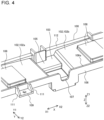
- Fig. 4 is an enlarged partial perspective view illustrating the configuration of the base unit 101 provided in the heat exchanger support device 100 according to Embodiment 1.
- Fig. 5 is a schematic plan view schematically illustrating the configuration of the base unit 101 provided in the heat exchanger support device 100 according to Embodiment 1.
- the heat exchanger support device 100 is a device that supports a heat exchanger 304 (see Fig. 6 ) housed in an outdoor unit 401 (see Fig. 8 ) of an air-conditioning apparatus 400 (see Fig. 8 ).
- the heat exchanger support device 100 is made of a resin.
- the heat exchanger support device 100 is disposed below a side surface 300a of a housing 300 of the outdoor unit 401, as illustrated in Fig. 8 , which will be discussed later.
- a Y1 direction of the Y direction is a direction from the inner side of the housing 300 to the outside, while a Y2 direction of the Y direction is a direction from the outer side to the inner side of the housing 300.
- Figs. 1 and 2 illustrate a state in which the heat exchanger support device 100 is seen in the direction from the outer side to the inner side.
- Figs. 3 and 4 illustrate a state in which the heat exchanger support device 100 is seen in the direction from the inner side to the outer side.
- the heat exchanger support device 100 is disposed between the heat exchanger 304 (see Fig. 6 ) stored in the housing 300 and a base 301, which will be discussed later, disposed below the heat exchanger 304 in the housing 300.
- the heat exchanger support device 100 includes a base unit 101 having a main surface 102, a groove 103, a first drain hole 104, and a water guide face 105.
- the base unit 101 forms the body of the heat exchanger support device 100.
- the base unit 101 has an elongated and planar shape.
- the base unit 101 has an inner edge 101a, which is one edge of the base unit 101 in the widthwise direction, and an outer edge 101b, which is the other edge of the base unit 101 in the widthwise direction.
- the inner edge 101a and the outer edge 101b both extend in the longitudinal direction of the base unit 101.
- the base unit 101 also has a side flat portion 112, as shown in Figs. 4 and 5 .
- the side flat portion 112 is provided at the outer edge 101b and extends in the X direction.
- the side flat portion 112 is disposed horizontally and thus parallel with the XY plane.
- the position of the side flat portion 112 in the Z direction may be the same as the position of a top end 106a of a side rib 106, which will be discussed later, in the Z direction, or may be different from the position of the top end 106a.
- the groove 103 is formed in the main surface 102 of the base unit 101.
- the groove 103 is a hollow, which is hollowed downward from the main surface 102.
- the groove 103 extends in the widthwise direction of the base unit 101.
- the groove 103 has a first end 103a, which is one end of the groove 103 in the extending direction, and a second end 103b, which is the other end of the groove 103 in the extending direction.
- the first end 103a is located closer to the inner edge 101a of the base unit 101 than is the second end 103b, which is located closer to the outer edge 101b of the base unit 101, than is the first end 103a.
- plural grooves 103 are each disposed with an associated space in between in the longitudinal direction of the base unit 101.
- the first drain hole 104 is located at the first end 103a of the groove 103, as shown in Fig. 2 .
- the first drain hole 104 is a through-hole passing through the planar thickness of the groove 103.
- the first drain hole 104 has a rectangular shape, for example, as viewed from above, as shown in Figs. 2 and 5 .
- the water guide face 105 is formed inside the groove 103.
- the water guide face 105 progressively or continuously descends from the second end 103b of the groove 103 toward the first drain hole 104. That is, as shown in Fig. 3 , the water guide face 105 has a step portion 1051 that progressively descends from the second end 103b of the groove 103 toward the first drain hole 104.
- the water guide face 105 has a tilt surface 1052 (see Fig. 7 ) that continuously descends from the second end 103b of the groove 103 toward the first drain hole 104.
- the water guide face 105 may be formed by a combination of the step portion 1051 and the tilt surface 1052. That is, the step portion 1051 may have the tilt surface 1052. In Embodiment 1, the step portion 1051 having the tilt surface 1052 will be explained as an example. This will be described below specifically.
- Fig. 6 is a perspective sectional view illustrating the configuration of the groove 103 provided in the heat exchanger support device 100 according to Embodiment 1.
- a cross section obtained by cutting the groove 103 in the heat exchanger support device 100 along a virtual plane parallel with the YZ plane is shown.
- the water guide face 105 is formed in the groove 103. Drain water generated and collected on the surface of the heat exchanger flows on the water guide face 105, as indicated by the arrow in Fig. 6 .
- the water guide face 105 has the step portion 1051, as shown in Fig. 6 .
- the step portion 1051 progressively descends in two steps from the second end 103b of the groove 103 toward the first drain hole 104.
- the number of steps of the step portion 1051 is not limited to two and may be determined appropriately.
- Fig. 7 is a sectional view illustrating the configuration of the groove 103 provided in the heat exchanger support device 100 according to Embodiment 1.
- the water guide face 105 has the tilt surface 1052.
- the tilt surface 1052 continuously descends from the second end 103b of the groove 103 toward the first drain hole 104.
- a step is formed on the tilt surface 1052.
- the provision of a step may be omitted, namely, the tilt surface 1052 may be one tilt surface.
- the tilt surface 1052 includes a first tilt surface portion 1052a, a second tilt surface portion 1052b, and a third tilt surface portion 1052c.
- the first tilt surface portion 1052a continuously descends in a direction from the second end 103b (see Fig. 5 ) toward the first end 103a (see Fig. 5 ) at a first tilt angle ⁇ 1.
- the second tilt surface portion 1052b is located closer to the first end 103a than is the first tilt surface portion 1052a. That is, the second tilt surface portion 1052b is located closer to the first end 103a than is the first tilt surface portion 1052a.
- the second tilt surface portion 1052b continuously descends in a direction from the second end 103b (see Fig.
- the third tilt surface portion 1052c links the first tilt surface portion 1052a and the second tilt surface portion 1052b to each other.
- the third tilt surface portion 1052c continuously descends in a direction from the second end 103b (see Fig. 5 ) toward the first end 103a (see Fig. 5 ) at a third tilt angle ⁇ 3.
- the third tilt angle ⁇ 3 is larger than each of the first tilt angle ⁇ 1 and the second tilt angle ⁇ 2. That is, the third tilt surface portion 1052c is the steepest surface.
- the first tilt angle ⁇ 1 is larger than or equal to the second tilt angle ⁇ 2. More specifically, the first tilt angle ⁇ 1 is about 4 to 5 degrees, the second title angle ⁇ 2 is about 3 to 4 degrees, and the third tilt angle ⁇ 3 is about 60 degrees.
- the step portion 1051 has two steps. This will be explained by taking the example in Figs. 6 and 7 .
- the step of the third tilt surface portion 1052c from the first tilt surface portion 1052a to the second tilt surface portion 1052b in the example in Fig. 7 is a first step, while a step 1052d from the second tilt surface portion 1052b toward the first drain hole 104 in Fig. 6 is a second step.
- a combination of the step portion 1051 and the tilt surface 1052 forms the water guide face 105.
- Providing one or more tilt surfaces 1052 in the step portion 1051 increases the flowrate of drain water and speedily discharges drain water.
- the steep third tilt surface portion 1052c is provided at the center of the step portion 1051 in the Y direction. Accordingly, even when the flowrate of drain water temporarily slows down on the first tilt surface portion 1052a because of the influence of accumulated wastes, for example, the drain water accelerates again on the third tilt surface portion 1052c and continues to flow down toward the second tilt surface portion 1052b. This prevents drain water from being stagnant and accumulated on the water guide face 105.
- the heat exchanger support device 100 includes a side rib 106, as shown in Fig. 4 .
- the side rib 106 is located at the inner edge 101a of the base unit 101.
- the side rib 106 has an elongated and planar shape extending in the longitudinal direction of the inner edge 101a of the base unit 101.
- the side rib 106 rises upward from the inner edge 101a in the Z direction.
- the side rib 106 has a corrugated shape in a side view.
- the side rib 106 has projecting portions protruding downward at positions corresponding to the positions of the grooves 103 in the base unit 101, and the remaining portions of the side rib 106 have an elongated, rectangular shape extending in the X direction.
- the side rib 106 has projecting portions located at positions corresponding to the grooves 103 formed in the longitudinal direction of the base unit 101 and rectangular, planar portions each positioned between corresponding projecting portions.
- a notch 107 is cut in the side rib 106.
- the notch 107 is cut at a top end 106a of the side rib 106.
- multiple notches 107 are cut at positions corresponding to the positions of the grooves 103 in the longitudinal direction of the base unit 101.
- the notches 107 are hollowed downward in the Z direction from the top end 106a of the side rib 106.
- drain water passes through the water guide face 105 and then flows through the notch 107 cut in the side rib 106, as indicated by the arrow in Fig. 15 , which will be discussed later.
- the water guide face 105 and the notch 107 define a second drain path P2, which is used when the first drain hole 104 is frozen.
- drain water passes through the water guide face 105 and the notch 107 and flows toward the base 301 located inside the housing 300. The drain water then flows from the base 301 toward the outside of the housing 300 of the outdoor unit 401 and is drained.
- the heat exchanger support device 100 includes a heat exchanger protection wall 200.
- the heat exchanger protection wall 200 is provided at the outer edge 101b, which is an edge of the base unit 101 in the widthwise direction.
- the heat exchanger protection wall 200 has an elongated and planar shape extending in the longitudinal direction of the outer edge 101b of the base unit 101.
- the heat exchanger protection wall 200 rises upward in the Z direction from the outer edge 101b.
- the heat exchanger protection wall 200 and the side rib 106 thus face each other.
- the heat exchanger 304 includes a heat exchanger header 307 connected to the bottom ends of multiple heat transfer tubes 305.
- the heat exchanger header 307 serves as a liquid header or a gas header.
- the heat exchanger protection wall 200 is disposed further outward of the housing 300 (see Fig. 8 ) of the outdoor unit 401 (see Fig. 8 ) than the heat exchanger header 307. That is, the heat exchanger protection wall 200 is disposed on the outer side of the heat exchanger header 307 and covers the heat exchanger header 307, as shown in Fig. 6 .
- the heat exchanger protection wall 200 and the heat exchanger header 307 do not contact each other and are separate from each other with a space in between.
- the heat exchanger protection wall 200 has a top bending portion 202 at the top of the heat exchanger protection wall 200. In the direction to the forward end of the top bending portion 202, the top bending portion 202 is inclined toward the heat exchanger 304 in the Z direction. The top bending portion 202 is bent along the outer shape of the top end of the heat exchanger header 307 and thus covers the top end of the heat exchanger header 307 from above. The top bending portion 202 and the top end of the heat exchanger header 307 do not contact each other and are separate from each other with a space in between.
- the heat exchanger protection wall 200 is disposed such that the heat exchanger protection wall 200 covers the heat exchanger header 307, thereby protecting the heat exchanger header 307 from damage, which may be caused by foreign matter, such as small stones, collided with the heat exchanger header 307. Since the heat exchanger protection wall 200 is disposed on the outer side of the heat exchanger header 307, it also serves as a windbreak panel for the heat exchanger header 307. The heat exchanger protection wall 200 thus prevents the heat exchanger header 307 from being frozen caused by wind. Because of the provision of the heat exchanger protection wall 200, outside air is taken into the outdoor unit 401 from the side surfaces 300a of the housing 300 for the heat exchanger 304 to allow heat exchange.
- the heat exchanger protection wall 200 includes drain gates 201, as shown in Fig. 2 .
- the drain gates 201 are provided at the bottom end of the heat exchanger protection wall 200.
- the drain gates 201 are formed such that the drain gates 201 are hollowed upward in the Z direction from a bottom end 200a of the heat exchanger protection wall 200.
- the drain gates 201 are narrow, slit-like gaps longitudinally extending in the X direction.
- the drain gates 201 define a fourth drain path P4, which will be discussed later, for draining drain water.
- the drain gates 201 are formed in a size that allows water to pass through the drain gates 201 and makes it difficult for foreign matter, such as small stones, wind, and insects, to enter.
- the heat exchanger protection wall 200 is made of a resin.
- the heat exchanger protection wall 200 may be formed as part of the heat exchanger support device 100, integrally with the base unit 101, for example.
- the heat exchanger protection wall 200 may be formed separately from the heat exchanger support device 100, such as the base unit 101, and be attached to the base unit 101, as shown in the exploded perspective view of Fig. 2 .
- the base unit 101, main surface 102, groove 103, first drain hole 104, water guide face 105, side rib 106, notch 107, and projecting portion 108, which will be discussed later, are integrally formed from a resin.
- Fig. 8 is a perspective view illustrating the external appearance of the outdoor unit 401 according to Embodiment 1.
- Fig. 9 is a perspective view illustrating the configuration of the base 301 located inside the housing 300 of the outdoor unit 401 according to Embodiment 1.
- Fig. 10 is an enlarged partial perspective view illustrating the configuration of the bottom portion of the outdoor unit 401 according to Embodiment 1.
- Fig. 11 is an exploded perspective view illustrating the configuration of the bottom portion of the outdoor unit 401 according to Embodiment 1.
- Fig. 12 is a perspective view illustrating the configurations of the base 301 and the heat exchanger support device 100 according to Embodiment 1.
- the outdoor unit 401 of the air-conditioning apparatus 400 includes the housing 300.
- the housing 300 has a cuboid shape, for example.
- the housing 300 has four side surfaces 300a and a top surface 300b.
- the heat exchanger support device 100 is mounted on a portion below at least one of the four side surfaces 300a.
- the side surface 300a on which the heat exchanger support device 100 is mounted may be called a front surface of the outdoor unit 401.
- the heat exchanger 304 allows heat exchange between sucked outside air and refrigerant flowing through the heat transfer tubes 305. Outside air subjected to heat exchange with the refrigerant is exhausted from the top surface 300b of the housing 300 to the outside.
- the heat exchanger 304 (see Fig. 6 ) is stored in the housing 300.
- the heat exchanger 304 includes heat transfer tubes 305 and fins 306 (see Fig. 22 ).
- the heat exchanger 304 is a fin-and-tube heat exchanger, for example.
- Fig. 22 is an exploded perspective view illustrating an example of the configuration of the heat exchanger 304 provided in the air-conditioning apparatus 400 according to Embodiment 1.
- the heat transfer tubes 305 axially extends in the up-down direction, that is, the Z direction, as shown in Figs. 6 and 22 .
- the heat transfer tubes 305 are flat tubes, for example.
- the plural heat transfer tubes 305 are each disposed in the X direction with an associated space in between, as shown in Fig. 22 .
- the flat surfaces of the heat transfer tubes 305 are parallel with the YZ plane and flat surfaces of adjacent heat transfer tubes 305 face each other.
- the heat transfer tubes 305 are arranged in two rows in the Y direction.
- the heat exchanger header 307 is provided for each row of heat transfer tubes 305.
- the heat transfer tubes 305 may not be disposed in two rows. That is, the number of rows of heat transfer tubes 305 may be any number including one.
- the fins 306 are corrugated fins, for example, but the fins 306 are not limited to this type. When the fins 306 are corrugated fins, each of the fins 306 is disposed between adjacent heat transfer tubes 305, as shown in Fig. 22 .
- a bolt is inserted into the screw hole and a nut is screwed into the bolt and thus fastens the heat exchanger protection wall 200 to the base leg 303, as shown in Fig. 6 .
- a leg cover 303c (see Fig. 18 ) is provided for the opening of the body 303a cut in the angular U shape. The provision of the leg cover 303c prevents the entry of foreign matter, such as small stones, into the base leg 303.
- the length of an installation region 309 of the heat exchanger 304 in the Y direction is defined as a "length L1", as shown in Fig. 6
- the length of the base unit 101 of the heat exchanger support device 100 in the Y direction is defined as a "length L2", as shown in Fig. 5
- the length L2 of the base unit 101 in the Y direction is longer than the length L1 of the installation region 309 of the heat exchanger 304 in the Y direction.
- the length L2 of the base unit 101 of the heat exchanger support device 100 in the widthwise direction is longer than the length L1, which is the entire length of the heat exchanger 304 in the depth direction.
- the installation region 309 of the heat exchanger 304 is a region where the heat transfer tubes 305 and the heat exchanger headers 307 of the heat exchanger 304 are installed.
- the base unit 101 is disposed such that the base unit 101 covers the entirety of the bottom surfaces of the heat exchangers 304 including the heat exchanger headers 307. Hence, the base unit 101 receives the entirety of drain water flowing down along the surfaces of the heat transfer tubes 305.
- the base 301 has a rectangular shape in a plan view.
- the base 301 is made of a corrugated steel plate. Working the base to have a corrugated shape can obtain the effect of making it easy for drain water to flow on the base and also the effect of providing a strength resistant to bending and deflection deformation to the base.
- the base 301 includes rising portions 301a at both ends in the X direction. The rising portions 301a are formed by bending both side edges of the base 301, which are provided in the X direction, upward in the Z direction.
- the base 301 also includes a second drain hole 302 and a drain groove 310.
- the drain groove 310 guides drain water to the second drain hole 302.
- the base 301 also has a front-surface side edge 301b, which forms one side edge in the Y direction, and a back-surface side edge 301c, which forms the other side edge in the Y direction.
- the second drain hole 302 is opened closer to the front-surface side edge 301b than the center in the Y direction.
- the second drain hole 302 is opened in the vicinity of the front-surface side edge 301b.
- Multiple second drain holes 302 are each provided in the X direction with an associated space in between.
- the drain groove 310 extends in the Y direction.
- the drain groove 310 is disposed in association with the corresponding second drain hole 302.
- the first drain hole 104 opened in the heat exchanger support device 100 is located right above the second drain hole 302 of the base 301.
- the first drain hole 104 is located inward of the second drain hole 302 of the base 301 and positioned at the same level as the second drain hole 302, as shown in Fig. 6 .
- the first drain hole 104 opened in the heat exchanger support device 100 is thus located at a position corresponding to the position of the second drain hole 302 of the base 301.
- the opening area of the first drain hole 104 is smaller than the opening area the second drain hole 302. Accordingly, the first drain hole 104 is contained in the second drain hole 302 as viewed from above.
- drain water flowing on the water guide face 105 and passing through the first drain hole 104 along the first drain path P1 is directly drained from the first drain hole 104 to the outside of the housing 300 without contacting the second drain hole 302 and the base 301.
- the base unit 101 includes the main surface 102, as discussed above.
- the main surface 102 has a first main surface 102a (see Fig. 4 ) and a second main surface 102b (see Fig. 4 ), which will be discussed later in detail with reference to Fig. 4 when the second drain path P2 is described.
- Each of the first and second main surfaces 102a and 102b is inclined and descends toward the groove 103. Since the first and second main surfaces 102a and 102b are inclined in the X direction, the drain water received by the main surface 102 of the base unit 101 flows toward the groove 103 in the X direction. Then, as illustrated in Figs.
- the drain water flowing down in the groove 103 flows on the water guide face 105 positioned in the groove 103 and reaches the first drain hole 104.
- the drain water is then directly drained from the first drain hole 104 to the outside of the housing 300 without contacting the second drain hole 302 and the base 301.
- the second drain path P2 is a drain path used when the first drain hole 104 is frozen.
- drain water flows by passing through the main surface 102, water guide face 105, and notch 107 of the heat exchanger support device 100, as indicated by the arrows in Figs. 14 and 15 . This will be described below in detail.
- the main surface 102 on the base unit 101 of the heat exchanger support device 100 includes the first main surface 102a and the second main surface 102b.
- the first main surface 102a and the second main surface 102b are located at one side and at the other side of the groove 103 in the longitudinal direction of the base unit 101, as shown in Fig. 4 .
- the first and second main surfaces 102a and 102b are inclined and descend toward the groove 103 in the longitudinal direction of the base unit 101, as shown in Fig. 4 .
- Projecting portions 108 are provided on the main surface 102, as shown in Fig. 4 .
- the heat exchanger header 307 is placed on the projecting portions 108 such that the projecting portions 108 support the heat exchanger header 307.
- Main surfaces 108a of the projecting portions 108 are not inclined and are located on a flat level.
- the first main surface 102a is located from the position at which a projecting portion 108 is provided to the position at which the groove 103 is formed. More specifically, the start point of the first main surface 102a corresponds to the center of the projecting portion 108 in the X direction. The end point of the first main surface 102a corresponds to one side of the groove 103 in the X direction. The first main surface 102a is inclined downward from the start point to the end point.
- the second main surface 102b is located from the position at which a projecting portion 108 is provided to the position at which the groove 103 is formed. More specifically, the start point of the second main surface 102b corresponds to the center of the projecting portion 108 in the X direction. The end point of the second main surface 102b corresponds to the other side of the groove 103 in the X direction. The second main surface 102b is inclined downward from the start point to the end point.
- drain water received by the main surface 102 flows toward the groove 103 in the X direction.
- the drain water flowing down in the groove 103 then passes through the water guide face 105 and flows from the notch 107 toward the base 301.
- the first and second main surfaces 102a and 102b are both inclined, not only in the X direction, but also in the Y direction. This will be explained by taking the second main surface 102b as an example with reference to Fig. 7 , which has been discussed.
- the second main surface 102b is inclined downward in a direction from the second end 103b to the first end 103a of the groove 103.
- the first main surface 102a is also inclined downward in a direction from the second end 103b to the first end 103a of the groove 103.
- drain water received by the main surface 102 flows toward the first end 103a of the groove 103 in the Y direction.
- the drain water flowing down in the groove 103 then passes through the water guide face 105 and flows from the notch 107 toward the base 301.
- first and second main surfaces 102a and 102b are inclined both in the X direction and in the Y direction, drain water efficiently flows toward the first drain hole 104 in the groove 103.
- the third drain path P3 is a drain path used when the first drain hole 104 and the notch 107 are frozen.
- drain water passes through the water guide face 105 and then flows by passing over the top end 106a of the side rib 106, as indicated by the arrows in Figs. 16 through 18 . This will be described below in detail.
- the water guide face 105 and the top end 106a of the side rib 106 define the third drain path P3. This prevents the heat exchanger header 307 from being submerged in (under) drain water.
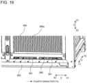
- FIG. 19 is a partial perspective view illustrating the fourth drain path P4 in the heat exchanger support device 100 according to Embodiment 1.
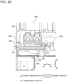
- Fig. 20 is a sectional view illustrating the fourth drain path P4 in the heat exchanger support device 100 according to Embodiment 1.
- the fourth drain path P4 is a drain path used when the first drain hole 104 and the notch 107 are frozen. As indicated by the arrows in Figs. 19 and 20 , when the first drain hole 104 and the notch 107 are frozen, drain water passes through the main surface 102 of the base unit 101 and the drain gates 201 of the heat exchanger protection wall 200 and flows toward the outside of the housing 300. This will be described below in detail.
- the drain gates 201 are provided at the bottom end of the heat exchanger protection wall 200.
- the drain gates 201 are narrow, slit-like gaps, as shown in Fig. 2 .
- the drain gates 201 are formed such that the drain gates 201 are hollowed upward from the bottom end 200a of the heat exchanger protection wall 200.
- drain water passes through the drain gates 201 and flows toward the outside of the housing 300.
- the main surface 102 of the base unit 101 and the drain gates 201 define the fourth drain path P4.
- Fig. 21 is a perspective view illustrating the configuration of a mounting portion 109 provided in the heat exchanger support device 100 according to Embodiment 1. As shown in Fig. 21 , the heat exchanger support device 100 includes the mounting portion 109 having a planar shape.
- the mounting portion 109 is fixed to the side rib 106.
- the mounting portion 109 has a rectangular shape in a plan view.
- the mounting portion 109 extends in a direction intersecting with the rising direction of the side rib 106. That is, the mounting portion 109 extends in the Y direction intersecting with the Z direction.
- the mounting portion 109 protrudes from the side rib 106 in a direction away from the base unit 101.
- the mounting portion 109 has a screw hole 110 passing through the planar thickness of the mounting portion 109.
- the mounting portion 109 is fastened to the base 301 by a screw inserted into the screw hole 110.
- the fixture inserted into the screw hole 110 may be a bolt and a nut.
- Planar reinforcing ribs 111 are provided for the mounting portion 109.
- the reinforcing ribs 111 are disposed at both ends of the mounting portion 109 in the longitudinal direction of the base unit 101.
- the reinforcing ribs 111 rise from both of the X-direction ends of the mounting portion 109 upward in the Z direction.
- the reinforcing ribs 111 have a triangular or pentagonal shape in a side view.
- An end 111a of each reinforcing rib 111 extending in the up-down direction is fixed to the side rib 106. Providing the reinforcing ribs 111 for the mounting portion 109 enhances the strength of the mounting portion 109.
- the first drain hole 104 may have a safety guard 113 that prevents the entry of foreign matter into the first drain hole 104.
- the foreign matter is a finger of a user, for example.
- the safety guard 113 has multiple bar-like components 113a fixed to both of the Y-direction ends of the first drain hole 104.
- the bar-like components 113a extend in the Y direction.
- the bar-like components 113a have a prism shape, for example, but may have a circular cylindrical shape.
- the multiple bar-like components 113a are each arranged in the X direction with an associated space in between.
- the safety guard 113 thus has a planar shape similar to one type of fence.
- the heat exchanger 304 is disposed above the first drain hole 104. More specifically, the heat exchanger header 307 of the heat exchanger 304 is disposed above the first drain hole 104. There may be a case in which the heat exchanger header 307 also serves as a gas header and, in this case, the heat exchanger header 307 becomes considerably hot.
- the safety guard 113 may thus be provided for the first drain hole 104 not to let a finger of a user put in the first drain hole 104 from outside. In this case, a finger of a user is hampered by the safety guard 113 and does not enter the first drain hole 104, thereby securing the safety.
- the safety guard 113 has a planar shape like one type of fence or a planar and lattice-like shape.
- the safety guard 113 is made of a heat-resistant resin, such as foaming resin.
- the safety guard 113 may be integrally formed from a resin, together with another element, such as the base unit 101.
- the safety guard 113 may be formed separately from another element, such as the base unit 101, and be attached to the inner side of the first drain hole 104.
- the heat exchanger support device 100 includes the main surface 102, groove 103, water guide face 105, and first drain hole 104.
- the heat exchanger support device 100 causes drain water received by the main surface 102 to flow down on the water guide face 105 in the groove 103 and to be drained to the outside of the housing 300 through the first drain hole 104.
- the first drain hole 104 is located right above the second drain hole 302 opened in the base 301 or inward of the second drain hole 302. Drain water is thus drained to the outside of the housing 300 without contacting the base 301.
- the heat exchanger support device 100 is made of a resin.
- the heat exchanger support device 100 is disposed between the heat exchanger header 307 made of aluminum and the base 301 made of steel.
- the heat exchanger support device 100 is thus configured to reduce the occurrence of galvanic corrosion.
- the second drain path P2 which causes drain water to flow down toward the inside of the housing 300 and to be drained, is provided and is used when the first drain hole 104 is frozen.
- the second drain path P2 includes the notch 107 cut in the side rib 106 of the heat exchanger support device 100.
- the third drain path P3 and the fourth drain path P4 for draining drain water are provided and are used when the first drain hole 104 and the notch 107 are frozen.
- the third drain path P3 includes the top end 106a of the side rib 106 located at a lower position than the installation position of the heat exchanger 304.
- the fourth drain path P4 includes the drain gates 201 provided in the heat exchanger protection wall 200.
- the heat exchanger support device 100 includes the notch 107 for draining water inside the housing 300, the side rib 106 located at a lower position than the installation position of the heat exchanger 304, and the drain gates 201 so that multiple drain paths are secured for draining water in case certain elements are frozen. Securing such multiple drain paths enhances the strength of the outdoor unit 401 in case the outdoor unit 401 is frozen.
- the heat exchanger protection wall 200 is provided for the heat exchanger support device 100.
- the heat exchanger protection wall 200 is disposed outside the heat exchanger header 307 and thus covers the heat exchanger header 307. This enables the heat exchanger protection wall 200 to protect the heat exchanger header 307 from damage caused by foreign matter, such as small stones, and to prevent the heat exchanger header 307 from being frozen caused by wind.
- 100 heat exchanger support device, 101: base unit, 101a: inner edge, 101b: outer edge, 102: main surface, 102a: first main surface, 102b: second main surface, 103: groove, 103a: first end, 103b: second end, 104: first drain hole, 105: water guide face, 106: side rib, 106a: top end, 107: notch, 108: projecting portion, 108a: main surface, 109: mounting portion, 110: screw hole, 111: reinforcing rib, 111a: end, 112: side flat portion, 113: safety guard, 113a: bar-like component, 200: heat exchanger protection wall, 200a: bottom end, 201: drain gate, 202: top bending portion, 300: housing, 300a: side surface, 300b: top surface, 301: base, 301a: rising portion, 301b: front-surface side edge, 301c: back-surface side edge, 302: second drain hole, 303: base leg, 303a
Landscapes
- Engineering & Computer Science (AREA)
- Mechanical Engineering (AREA)
- General Engineering & Computer Science (AREA)
- Chemical & Material Sciences (AREA)
- Combustion & Propulsion (AREA)
- Physics & Mathematics (AREA)
- Thermal Sciences (AREA)
- Transportation (AREA)
- Other Air-Conditioning Systems (AREA)
- Air Filters, Heat-Exchange Apparatuses, And Housings Of Air-Conditioning Units (AREA)
Abstract
Description
- The present disclosure relates to a heat exchanger support device that supports a heat exchanger.
- As a typical type of air-conditioning apparatus, an air-conditioning apparatus configured to perform a cooling operation and a heating operation by switching the flows of refrigerant by use of a flow switching device, such as a four-way valve, is known. When the air-conditioning apparatus performs the heating operation in the environment where outside temperature is low, frost adheres to a heat exchanger of an outdoor unit, thereby lowering the heat exchange efficiency. For this reason, the outdoor unit typically has a defrost function.
- The outdoor unit causes frost melted by a defrost operation to flow downward as melt water. The melt water is received by a metal base disposed at a lower internal space of the outdoor unit and is then drained to the outside from a drain hole opened in the metal base. However, the metal base has a corrugated shape and because of this shape, part of the melt water received by the metal base may not reach the drain hole and remain on the metal base. After the air-conditioning apparatus finishes the defrost operation and returns to the heating operation, the melt water remaining on the metal base is frozen again when the outside temperature is below the freezing point of water. Because the defrost operation for the heat exchanger is regularly performed, the frozen melt water is expanded, and the entire metal base is covered with ice.
- When the metal base is covered with ice in this manner, the drain hole opened in the metal base is blocked by the ice, thereby failing to drain melt water. This promotes the growth of ice to the bottom portion of the heat exchanger, which crushes aluminum fins provided in the heat exchanger. When ice further grows to reach heat transfer tubes, the heat transfer tubes are damaged, leading to a leakage of a refrigerant gas in the worst case.
- Additionally, when a heat exchanger includes heat transfer tubes axially extending in the up-down direction, a heat exchanger header, such as a liquid header and a gas header, is provided at the bottom portion of the heat exchanger. The heat exchanger header is made of aluminum and may be damaged by ice that has grown. Hence, when a heat exchanger header is provided at the bottom portion of a heat exchanger, the risk of a gas leakage caused by the freezing and the melting of water becomes even higher.
- To address this issue, Patent Literature 1, for example, discloses a technology for preventing melt water from being frozen by installing a freeze preventing heater on the metal base of the outdoor unit.
- Patent Literature 1: International Publication No.
2013/088713 - As in the outdoor unit disclosed in Patent Literature 1, however, even with the freeze preventing heater installed on the metal base, the freezing of melt water is not completely prevented. That is, in actuality, the freeze preventing heater merely melts ice in the vicinity of the freeze preventing heater, and melt water still freezes in an area without the freeze preventing heater. As a result, the top portion of the freeze preventing heater is eventually frozen and ice is formed on the entire surface of the metal base. This may damage some elements of the heat exchanger, such as aluminum fins and heat transfer tubes.
- Additionally, the heat exchanger header is made of an aluminum material, while the metal base is made of a steel plate, thereby increasing the occurrence of galvanic corrosion. Galvanic corrosion may cause the removal of a coating, for example, and the removal of a coating on the metal base, for example, directly leads to a serious defect.
- The present disclosure has been made to solve the above-described problems. It is an object of the present disclosure to provide a heat exchanger support device configured to prevent damage to a heat exchanger, which would be caused by the freezing of the heat exchanger, by efficiently draining drain water from the heat exchanger and also configured to reduce the occurrence of galvanic corrosion. In the following description, drain water includes melt water generated from frost melted by a defrost operation and drain water caused by moisture condensation in air and adhering to the surface of heat transfer tubes.
- A heat exchanger support device of an embodiment of the present disclosure is a heat exchanger support device that is disposed between a heat exchanger and a base, which is disposed below the heat exchanger. The heat exchanger support device is made of a resin. The heat exchanger support device includes a base unit, a groove, a first drain hole, and a water guide face. The base unit has an elongated and planar shape and includes a main surface, which is flat. The groove is formed in the main surface of the base unit. The groove is hollowed downward from the main surface and extends in a widthwise direction of the base unit. The first drain hole is opened at a first end of the groove, which is an end in an extending direction of the groove. The first drain hole is a through-hole passing through a planar thickness of the groove. The water guide face is formed in the groove and progressively or continuously descends from a second end of the groove toward the first drain hole opened at the first end. The second end is positioned opposite to the first end in the extending direction of the groove.
- A heat exchanger support device according to an embodiment of the present disclosure is configured to cause drain water to flow down on a water guide face in a groove and to be drained to the outside through a first drain hole opened in a resin. Drain water of a heat exchanger is thus drained without contacting a base. This prevents damage to the heat exchanger, which would be caused by drain water becoming frozen on the base. The heat exchanger support device is made of a resin and is disposed between the base made of steel and the heat exchanger made of aluminum, thereby making it possible to reduce the occurrence of galvanic corrosion. Brief Description of Drawings
-
- [
Fig. 1] Fig. 1 is a perspective view illustrating the configuration of a heatexchanger support device 100 according to Embodiment 1. - [
Fig. 2] Fig. 2 is an exploded perspective view illustrating the configuration of the heatexchanger support device 100 according to Embodiment 1. - [
Fig. 3] Fig. 3 is a perspective view illustrating abase unit 101 provided in the heatexchanger support device 100 according to Embodiment 1. - [
Fig. 4] Fig. 4 is an enlarged partial perspective view illustrating the configuration of thebase unit 101 provided in the heatexchanger support device 100 according to Embodiment 1. - [
Fig. 5] Fig. 5 is a schematic plan view schematically illustrating the configuration of thebase unit 101 provided in the heatexchanger support device 100 according to Embodiment 1. - [
Fig. 6] Fig. 6 is a perspective sectional view illustrating the configuration of agroove 103 provided in the heatexchanger support device 100 according to Embodiment 1. - [
Fig. 7] Fig. 7 is a sectional view illustrating the configuration of thegroove 103 provided in the heatexchanger support device 100 according to Embodiment 1. - [
Fig. 8] Fig. 8 is a perspective view illustrating the external appearance of anoutdoor unit 401 according to Embodiment 1. - [
Fig. 9] Fig. 9 is a perspective view illustrating the configuration of abase 301 located inside ahousing 300 of theoutdoor unit 401 according to Embodiment 1. - [
Fig. 10] Fig. 10 is an enlarged partial perspective view illustrating the configuration of a bottom portion of theoutdoor unit 401 according to Embodiment 1. - [
Fig. 11] Fig. 11 is an exploded perspective view illustrating the configuration of the bottom portion of theoutdoor unit 401 according to Embodiment 1. - [
Fig. 12] Fig. 12 is a perspective view illustrating the configurations of thebase 301 and the heatexchanger support device 100 according to Embodiment 1. - [
Fig. 13] Fig. 13 is a partial perspective view illustrating a first drain path P1 in the heatexchanger support device 100 according to Embodiment 1. - [
Fig. 14] Fig. 14 is a partial perspective view illustrating a second drain path P2 in the heatexchanger support device 100 according to Embodiment 1. - [
Fig. 15] Fig. 15 is a partial perspective view illustrating the second drain path P2 in the heatexchanger support device 100 according to Embodiment 1. - [
Fig. 16] Fig. 16 is a partial perspective view illustrating a third drain path P3 in the heatexchanger support device 100 according to Embodiment 1. - [
Fig. 17] Fig. 17 is a partial perspective view illustrating the third drain path P3 in the heatexchanger support device 100 according to Embodiment 1. - [
Fig. 18] Fig. 18 is a partial perspective view illustrating the third drain path P3 in the heatexchanger support device 100 according to Embodiment 1. - [
Fig. 19] Fig. 19 is a partial perspective view illustrating a fourth drain path P4 in the heatexchanger support device 100 according to Embodiment 1. - [
Fig. 20] Fig. 20 is a sectional view illustrating the fourth drain path P4 in the heatexchanger support device 100 according to Embodiment 1. - [
Fig. 21] Fig. 21 is a perspective view illustrating the configuration of a mountingportion 109 provided in the heatexchanger support device 100 according to Embodiment 1. - [
Fig. 22] Fig. 22 is an exploded perspective view illustrating an example of the configuration of aheat exchanger 304 provided in an air-conditioning apparatus 400 according to Embodiment 1. - A heat exchanger support device according to the present disclosure will be described below with reference to the drawings. The present disclosure is not limited to the following embodiment and may be variously modified without departing from the scope and the spirit of the present disclosure. The present disclosure includes all kinds of combinations of the configurations of the following embodiment and modified examples when such combinations are possible. In the drawings, elements designated by the same reference sign are the same element or corresponding elements. This applies to all text throughout the specification. The relative relationship between the sizes of elements or the shapes of the elements shown in the drawings may be different from those of actual elements. In the drawings, the Z direction represents the up-down direction. The Z direction is a vertical direction, for example. The X direction is a direction intersecting with the Z direction and represents the longitudinal direction of the heat exchanger support device. The X direction is a horizontal direction, for example. The X direction may be called the widthwise direction of a heat exchanger. The Y direction is a direction intersecting with the Z direction and the X direction and represents the widthwise direction of the heat exchanger support device. The Y direction is a horizontal direction, for example. The Y direction may be called the depth direction of the heat exchanger.
- The configuration of a heat
exchanger support device 100 will be described below with reference toFigs. 1 through 5 .Fig. 1 is a perspective view illustrating the configuration of the heatexchanger support device 100 according to Embodiment 1.Fig. 2 is an exploded perspective view illustrating the configuration of the heatexchanger support device 100 according to Embodiment 1.Fig. 3 is a perspective view illustrating abase unit 101 provided in the heatexchanger support device 100 according to Embodiment 1.Fig. 4 is an enlarged partial perspective view illustrating the configuration of thebase unit 101 provided in the heatexchanger support device 100 according to Embodiment 1.Fig. 5 is a schematic plan view schematically illustrating the configuration of thebase unit 101 provided in the heatexchanger support device 100 according to Embodiment 1. - The heat
exchanger support device 100 according to Embodiment 1 is a device that supports a heat exchanger 304 (seeFig. 6 ) housed in an outdoor unit 401 (seeFig. 8 ) of an air-conditioning apparatus 400 (seeFig. 8 ). The heatexchanger support device 100 is made of a resin. The heatexchanger support device 100 is disposed below aside surface 300a of ahousing 300 of theoutdoor unit 401, as illustrated inFig. 8 , which will be discussed later. InFigs. 1 through 5 , a Y1 direction of the Y direction is a direction from the inner side of thehousing 300 to the outside, while a Y2 direction of the Y direction is a direction from the outer side to the inner side of thehousing 300.Figs. 1 and2 illustrate a state in which the heatexchanger support device 100 is seen in the direction from the outer side to the inner side.Figs. 3 and4 illustrate a state in which the heatexchanger support device 100 is seen in the direction from the inner side to the outer side. The heatexchanger support device 100 is disposed between the heat exchanger 304 (seeFig. 6 ) stored in thehousing 300 and abase 301, which will be discussed later, disposed below theheat exchanger 304 in thehousing 300. - As illustrated in
Figs. 1 through 5 , the heatexchanger support device 100 includes abase unit 101 having amain surface 102, agroove 103, afirst drain hole 104, and awater guide face 105. - The
base unit 101 forms the body of the heatexchanger support device 100. Thebase unit 101 has an elongated and planar shape. Thebase unit 101 has aninner edge 101a, which is one edge of thebase unit 101 in the widthwise direction, and anouter edge 101b, which is the other edge of thebase unit 101 in the widthwise direction. Theinner edge 101a and theouter edge 101b both extend in the longitudinal direction of thebase unit 101. When the heatexchanger support device 100 is mounted on thehousing 300 of theoutdoor unit 401, theinner edge 101a is positioned in an internal space of the housing 300 (seeFig. 8 ), while theouter edge 101b is positioned on the outer side of the housing 300 (seeFig. 8 ). Thebase unit 101 has a flatmain surface 102, which will be discussed later. Thebase unit 101 also has a sideflat portion 112, as shown inFigs. 4 and5 . The sideflat portion 112 is provided at theouter edge 101b and extends in the X direction. The sideflat portion 112 is disposed horizontally and thus parallel with the XY plane. The position of the sideflat portion 112 in the Z direction, that is, the height position, may be the same as the position of atop end 106a of aside rib 106, which will be discussed later, in the Z direction, or may be different from the position of thetop end 106a. - The
groove 103 is formed in themain surface 102 of thebase unit 101. Thegroove 103 is a hollow, which is hollowed downward from themain surface 102. Thegroove 103 extends in the widthwise direction of thebase unit 101. As shown inFig. 2 , thegroove 103 has afirst end 103a, which is one end of thegroove 103 in the extending direction, and asecond end 103b, which is the other end of thegroove 103 in the extending direction. Thefirst end 103a is located closer to theinner edge 101a of thebase unit 101 than is thesecond end 103b, which is located closer to theouter edge 101b of thebase unit 101, than is thefirst end 103a. As shown inFig. 2 ,plural grooves 103 are each disposed with an associated space in between in the longitudinal direction of thebase unit 101. - The
first drain hole 104 is located at thefirst end 103a of thegroove 103, as shown inFig. 2 . Thefirst drain hole 104 is a through-hole passing through the planar thickness of thegroove 103. Thefirst drain hole 104 has a rectangular shape, for example, as viewed from above, as shown inFigs. 2 and5 . - The
water guide face 105 is formed inside thegroove 103. Thewater guide face 105 progressively or continuously descends from thesecond end 103b of thegroove 103 toward thefirst drain hole 104. That is, as shown inFig. 3 , thewater guide face 105 has astep portion 1051 that progressively descends from thesecond end 103b of thegroove 103 toward thefirst drain hole 104. Alternatively, thewater guide face 105 has a tilt surface 1052 (seeFig. 7 ) that continuously descends from thesecond end 103b of thegroove 103 toward thefirst drain hole 104. Thewater guide face 105 may be formed by a combination of thestep portion 1051 and thetilt surface 1052. That is, thestep portion 1051 may have thetilt surface 1052. In Embodiment 1, thestep portion 1051 having thetilt surface 1052 will be explained as an example. This will be described below specifically. -
Fig. 6 is a perspective sectional view illustrating the configuration of thegroove 103 provided in the heatexchanger support device 100 according to Embodiment 1. InFig. 6 , a cross section obtained by cutting thegroove 103 in the heatexchanger support device 100 along a virtual plane parallel with the YZ plane is shown. As illustrated inFig. 6 , thewater guide face 105 is formed in thegroove 103. Drain water generated and collected on the surface of the heat exchanger flows on thewater guide face 105, as indicated by the arrow inFig. 6 . Thewater guide face 105 has thestep portion 1051, as shown inFig. 6 . In the example inFig. 6 , thestep portion 1051 progressively descends in two steps from thesecond end 103b of thegroove 103 toward thefirst drain hole 104. The number of steps of thestep portion 1051 is not limited to two and may be determined appropriately. -
Fig. 7 is a sectional view illustrating the configuration of thegroove 103 provided in the heatexchanger support device 100 according to Embodiment 1. As illustrated inFig. 7 , thewater guide face 105 has thetilt surface 1052. Thetilt surface 1052 continuously descends from thesecond end 103b of thegroove 103 toward thefirst drain hole 104. In the example inFig. 7 , because of the provision of thestep portion 1051, a step is formed on thetilt surface 1052. Alternatively, the provision of a step may be omitted, namely, thetilt surface 1052 may be one tilt surface. - In the example in
Fig. 7 , thetilt surface 1052 includes a firsttilt surface portion 1052a, a secondtilt surface portion 1052b, and a thirdtilt surface portion 1052c. The firsttilt surface portion 1052a continuously descends in a direction from thesecond end 103b (seeFig. 5 ) toward thefirst end 103a (seeFig. 5 ) at a first tilt angle α1. The secondtilt surface portion 1052b is located closer to thefirst end 103a than is the firsttilt surface portion 1052a. That is, the secondtilt surface portion 1052b is located closer to thefirst end 103a than is the firsttilt surface portion 1052a. The secondtilt surface portion 1052b continuously descends in a direction from thesecond end 103b (seeFig. 5 ) toward thefirst end 103a (seeFig. 5 ) at a second tilt angle α2. The thirdtilt surface portion 1052c links the firsttilt surface portion 1052a and the secondtilt surface portion 1052b to each other. The thirdtilt surface portion 1052c continuously descends in a direction from thesecond end 103b (seeFig. 5 ) toward thefirst end 103a (seeFig. 5 ) at a third tilt angle α3. The third tilt angle α3 is larger than each of the first tilt angle α1 and the second tilt angle α2. That is, the thirdtilt surface portion 1052c is the steepest surface. The first tilt angle α1 is larger than or equal to the second tilt angle α2. More specifically, the first tilt angle α1 is about 4 to 5 degrees, the second title angle α2 is about 3 to 4 degrees, and the third tilt angle α3 is about 60 degrees. These numerical values are only examples, and the tilt angles are not limited to the examples. - It has been explained that the
step portion 1051 has two steps. This will be explained by taking the example inFigs. 6 and7 . The step of the thirdtilt surface portion 1052c from the firsttilt surface portion 1052a to the secondtilt surface portion 1052b in the example inFig. 7 is a first step, while astep 1052d from the secondtilt surface portion 1052b toward thefirst drain hole 104 inFig. 6 is a second step. In this manner, in Embodiment 1, a combination of thestep portion 1051 and thetilt surface 1052 forms thewater guide face 105. Providing one ormore tilt surfaces 1052 in thestep portion 1051 increases the flowrate of drain water and speedily discharges drain water. In Embodiment 1, the steep thirdtilt surface portion 1052c is provided at the center of thestep portion 1051 in the Y direction. Accordingly, even when the flowrate of drain water temporarily slows down on the firsttilt surface portion 1052a because of the influence of accumulated wastes, for example, the drain water accelerates again on the thirdtilt surface portion 1052c and continues to flow down toward the secondtilt surface portion 1052b. This prevents drain water from being stagnant and accumulated on thewater guide face 105. - The heat
exchanger support device 100 includes aside rib 106, as shown inFig. 4 . As illustrated inFigs. 2 and3 , theside rib 106 is located at theinner edge 101a of thebase unit 101. Theside rib 106 has an elongated and planar shape extending in the longitudinal direction of theinner edge 101a of thebase unit 101. Theside rib 106 rises upward from theinner edge 101a in the Z direction. As shown inFig. 3 , theside rib 106 has a corrugated shape in a side view. That is, theside rib 106 has projecting portions protruding downward at positions corresponding to the positions of thegrooves 103 in thebase unit 101, and the remaining portions of theside rib 106 have an elongated, rectangular shape extending in the X direction. In this manner, theside rib 106 has projecting portions located at positions corresponding to thegrooves 103 formed in the longitudinal direction of thebase unit 101 and rectangular, planar portions each positioned between corresponding projecting portions. - As shown in
Fig. 4 , anotch 107 is cut in theside rib 106. Thenotch 107 is cut at atop end 106a of theside rib 106. As illustrated inFigs. 2 through 4 ,multiple notches 107 are cut at positions corresponding to the positions of thegrooves 103 in the longitudinal direction of thebase unit 101. Thenotches 107 are hollowed downward in the Z direction from thetop end 106a of theside rib 106. - Under normal conditions, drain water passes through the
water guide face 105 and flows toward thefirst drain hole 104 along a first drain path P1, as indicated by the arrow inFig. 6 . As shown inFig. 6 , thefirst drain hole 104 is located at a position corresponding to the position of asecond drain hole 302 opened in abase 301, which will be discussed later. Thefirst drain hole 104 is located right above thesecond drain hole 302 or is located inward of thesecond drain hole 302 and positioned at the same level as thesecond drain hole 302. Thewater guide face 105 and thefirst drain hole 104 define the first drain path P1 through which drain water flows. In the first drain path P1, drain water is allowed to flow on thewater guide face 105, pass through thefirst drain hole 104, and be directly drained to the outside of thehousing 300 of theoutdoor unit 401 without contacting thebase 301. - However, there may be a case in which drain water is frozen in the vicinity of the
first drain hole 104 and thefirst drain hole 104 is blocked by the frozen water. In this case, drain water passes through thewater guide face 105 and then flows through thenotch 107 cut in theside rib 106, as indicated by the arrow inFig. 15 , which will be discussed later. Thewater guide face 105 and thenotch 107 define a second drain path P2, which is used when thefirst drain hole 104 is frozen. In the second drain path P2, drain water passes through thewater guide face 105 and thenotch 107 and flows toward the base 301 located inside thehousing 300. The drain water then flows from the base 301 toward the outside of thehousing 300 of theoutdoor unit 401 and is drained. - As illustrated in
Figs. 1 and2 , the heatexchanger support device 100 includes a heatexchanger protection wall 200. The heatexchanger protection wall 200 is provided at theouter edge 101b, which is an edge of thebase unit 101 in the widthwise direction. The heatexchanger protection wall 200 has an elongated and planar shape extending in the longitudinal direction of theouter edge 101b of thebase unit 101. The heatexchanger protection wall 200 rises upward in the Z direction from theouter edge 101b. The heatexchanger protection wall 200 and theside rib 106 thus face each other. - As illustrated in
Fig. 6 , theheat exchanger 304 includes aheat exchanger header 307 connected to the bottom ends of multipleheat transfer tubes 305. Theheat exchanger header 307 serves as a liquid header or a gas header. As shown inFig. 6 , the heatexchanger protection wall 200 is disposed further outward of the housing 300 (seeFig. 8 ) of the outdoor unit 401 (seeFig. 8 ) than theheat exchanger header 307. That is, the heatexchanger protection wall 200 is disposed on the outer side of theheat exchanger header 307 and covers theheat exchanger header 307, as shown inFig. 6 . The heatexchanger protection wall 200 and theheat exchanger header 307 do not contact each other and are separate from each other with a space in between. The heatexchanger protection wall 200 has atop bending portion 202 at the top of the heatexchanger protection wall 200. In the direction to the forward end of thetop bending portion 202, thetop bending portion 202 is inclined toward theheat exchanger 304 in the Z direction. Thetop bending portion 202 is bent along the outer shape of the top end of theheat exchanger header 307 and thus covers the top end of theheat exchanger header 307 from above. Thetop bending portion 202 and the top end of theheat exchanger header 307 do not contact each other and are separate from each other with a space in between. In this manner, the heatexchanger protection wall 200 is disposed such that the heatexchanger protection wall 200 covers theheat exchanger header 307, thereby protecting theheat exchanger header 307 from damage, which may be caused by foreign matter, such as small stones, collided with theheat exchanger header 307. Since the heatexchanger protection wall 200 is disposed on the outer side of theheat exchanger header 307, it also serves as a windbreak panel for theheat exchanger header 307. The heatexchanger protection wall 200 thus prevents theheat exchanger header 307 from being frozen caused by wind. Because of the provision of the heatexchanger protection wall 200, outside air is taken into theoutdoor unit 401 from the side surfaces 300a of thehousing 300 for theheat exchanger 304 to allow heat exchange. Without the heatexchanger protection wall 200, outside air is also sucked in from downward of thehousing 300. This outside air is not used for heat exchange, thereby lowering the heat exchange efficiency of theheat exchanger 304. In Embodiment 1, the provision of the heatexchanger protection wall 200 maintains the heat exchange efficiency. The heatexchanger protection wall 200 also prevents the entry of insects into thehousing 300. - The heat
exchanger protection wall 200 includesdrain gates 201, as shown inFig. 2 . Thedrain gates 201 are provided at the bottom end of the heatexchanger protection wall 200. Thedrain gates 201 are formed such that thedrain gates 201 are hollowed upward in the Z direction from abottom end 200a of the heatexchanger protection wall 200. Thedrain gates 201 are narrow, slit-like gaps longitudinally extending in the X direction. Thedrain gates 201 define a fourth drain path P4, which will be discussed later, for draining drain water. Thedrain gates 201 are formed in a size that allows water to pass through thedrain gates 201 and makes it difficult for foreign matter, such as small stones, wind, and insects, to enter. - The heat
exchanger protection wall 200 is made of a resin. The heatexchanger protection wall 200 may be formed as part of the heatexchanger support device 100, integrally with thebase unit 101, for example. Alternatively, the heatexchanger protection wall 200 may be formed separately from the heatexchanger support device 100, such as thebase unit 101, and be attached to thebase unit 101, as shown in the exploded perspective view ofFig. 2 . - The
base unit 101,main surface 102,groove 103,first drain hole 104,water guide face 105,side rib 106,notch 107, and projectingportion 108, which will be discussed later, are integrally formed from a resin. - The configuration of the
outdoor unit 401 of the air-conditioning apparatus 400 will be explained below with reference toFigs. 8 through 12 .Fig. 8 is a perspective view illustrating the external appearance of theoutdoor unit 401 according to Embodiment 1.Fig. 9 is a perspective view illustrating the configuration of the base 301 located inside thehousing 300 of theoutdoor unit 401 according to Embodiment 1.Fig. 10 is an enlarged partial perspective view illustrating the configuration of the bottom portion of theoutdoor unit 401 according to Embodiment 1.Fig. 11 is an exploded perspective view illustrating the configuration of the bottom portion of theoutdoor unit 401 according to Embodiment 1.Fig. 12 is a perspective view illustrating the configurations of thebase 301 and the heatexchanger support device 100 according to Embodiment 1. - As illustrated in
Fig. 8 , theoutdoor unit 401 of the air-conditioning apparatus 400 includes thehousing 300. Thehousing 300 has a cuboid shape, for example. Thehousing 300 has fourside surfaces 300a and atop surface 300b. The heatexchanger support device 100 is mounted on a portion below at least one of the fourside surfaces 300a. Theside surface 300a on which the heatexchanger support device 100 is mounted may be called a front surface of theoutdoor unit 401. - An air-sending
fan 308 is provided above the inside of thehousing 300. In the example inFig. 8 , theoutdoor unit 401 includes two heat exchangers 304 (seeFig. 6 ) and two air-sendingfans 308. However, this is only an example. Theoutdoor unit 401 may include oneheat exchanger 304 and one air-sendingfan 308. When twoheat exchangers 304 are stored in thehousing 300, theheat exchangers 304 are arranged side by side in the X direction. Likewise, when two air-sendingfans 308 are stored in thehousing 300, the air-sendingfans 308 are arranged side by side in the X direction, as shown inFig. 8 . When the air-sendingfan 308 is driven and rotated, outside air is sucked into thehousing 300 from the side surfaces 300a of thehousing 300. Theheat exchanger 304 allows heat exchange between sucked outside air and refrigerant flowing through theheat transfer tubes 305. Outside air subjected to heat exchange with the refrigerant is exhausted from thetop surface 300b of thehousing 300 to the outside. - The heat exchanger 304 (see
Fig. 6 ) is stored in thehousing 300. Theheat exchanger 304 includesheat transfer tubes 305 and fins 306 (seeFig. 22 ). Theheat exchanger 304 is a fin-and-tube heat exchanger, for example.Fig. 22 is an exploded perspective view illustrating an example of the configuration of theheat exchanger 304 provided in the air-conditioning apparatus 400 according to Embodiment 1. Theheat transfer tubes 305 axially extends in the up-down direction, that is, the Z direction, as shown inFigs. 6 and22 . Theheat transfer tubes 305 are flat tubes, for example. The pluralheat transfer tubes 305 are each disposed in the X direction with an associated space in between, as shown inFig. 22 . The flat surfaces of theheat transfer tubes 305 are parallel with the YZ plane and flat surfaces of adjacentheat transfer tubes 305 face each other. In the examples inFigs. 6 and22 , theheat transfer tubes 305 are arranged in two rows in the Y direction. Theheat exchanger header 307 is provided for each row ofheat transfer tubes 305. However, theheat transfer tubes 305 may not be disposed in two rows. That is, the number of rows ofheat transfer tubes 305 may be any number including one. Thefins 306 are corrugated fins, for example, but thefins 306 are not limited to this type. When thefins 306 are corrugated fins, each of thefins 306 is disposed between adjacentheat transfer tubes 305, as shown inFig. 22 . When thefins 306 are planar fins, thefins 306 are each disposed with an associated space in between in a direction intersecting with the axial direction of theheat transfer tubes 305, and theheat transfer tubes 305 are disposed such that theheat transfer tubes 305 pass through thefins 306. As illustrated inFig. 6 , theheat exchanger headers 307 are connected to the bottom ends of theheat transfer tubes 305. - As illustrated in
Fig. 8 , the heatexchanger support device 100 is mounted on a portion below theside surface 300a of thehousing 300. In the example inFig. 8 , one heatexchanger support device 100 is mounted on thehousing 300, but this is only an example. Since the twoheat exchangers 304 are provided in thehousing 300, two heatexchanger support devices 100 may be mounted on thehousing 300 and are associated with therespective heat exchangers 304. Thebase unit 101 of the heatexchanger support device 100 is located in thehousing 300, as shown in the perspective view ofFig. 10 and the exploded perspective view ofFig. 11 . Theinner edge 101a (seeFig. 1 ) of thebase unit 101 is located in the internal space of thehousing 300. Theouter edge 101b (seeFig. 1 ) of thebase unit 101 is also located in the internal space of thehousing 300, but is located further outward of thehousing 300 than is theinner edge 101a. Theinner edge 101a and theouter edge 101b face each other, as shown inFig. 5 . The heatexchanger protection wall 200 is disposed in the same plane as theside surface 300a of thehousing 300 and is exposed outside. -
Base legs 303 are provided at a lower portion of thehousing 300, as shown inFig. 8 . Thebase legs 303 are support components that support the base 301 (seeFig. 9 ) disposed under the internal space of thehousing 300. Abody 303a of thebase leg 303 has an angular U shape in a side view, as shown inFig. 6 , and is opened toward the outside of thehousing 300. A mountingportion 303b is provided at the top edge of thebody 303a of thebase leg 303. The mountingportion 303b extends upward in the Z direction from the top edge of thebody 303a. A screw hole is opened in the mountingportion 303b. A bolt is inserted into the screw hole and a nut is screwed into the bolt and thus fastens the heatexchanger protection wall 200 to thebase leg 303, as shown inFig. 6 . When necessary, aleg cover 303c (seeFig. 18 ) is provided for the opening of thebody 303a cut in the angular U shape. The provision of theleg cover 303c prevents the entry of foreign matter, such as small stones, into thebase leg 303. - As illustrated in
Figs. 6 ,10, and 11 , the heatexchanger support device 100 is disposed such that the longitudinal direction of thebase unit 101 is parallel with the widthwise direction of theheat exchanger 304. The widthwise direction of theheat exchanger 304 is the stacking direction of theheat transfer tubes 305 and is the X direction. The heatexchanger support device 100 is disposed such that the widthwise direction of thebase unit 101 is parallel with the depth direction of theheat exchanger 304. The depth direction of theheat exchanger 304 is a direction intersecting with the stacking direction of theheat transfer tubes 305, and more specifically, it is the Y direction. - The length of an
installation region 309 of theheat exchanger 304 in the Y direction is defined as a "length L1", as shown inFig. 6 , while the length of thebase unit 101 of the heatexchanger support device 100 in the Y direction is defined as a "length L2", as shown inFig. 5 . The length L2 of thebase unit 101 in the Y direction is longer than the length L1 of theinstallation region 309 of theheat exchanger 304 in the Y direction. In this manner, the length L2 of thebase unit 101 of the heatexchanger support device 100 in the widthwise direction is longer than the length L1, which is the entire length of theheat exchanger 304 in the depth direction. Theinstallation region 309 of theheat exchanger 304 is a region where theheat transfer tubes 305 and theheat exchanger headers 307 of theheat exchanger 304 are installed. - A length L3 (see
Fig. 3 ) of thebase unit 101 of the heatexchanger support device 100 in the longitudinal direction is longer than or equal to a length L4 (seeFig. 22 ), which is the entire length of the installation region 309 (seeFig. 22 ) of theheat exchanger 304 in the X direction. In this manner, the length L3 of thebase unit 101 of the heatexchanger support device 100 in the longitudinal direction is longer than the length L4, which is the entire length of theheat exchanger 304 in the widthwise direction. In the example inFig. 8 , twoheat exchangers 304 are provided in thehousing 300. Whenplural heat exchangers 304 are provided as in this example, the length L4 of the installation region 309 (seeFig. 22 ) of theheat exchangers 304 in the X direction is the total length of all theheat exchangers 304 stored in thehousing 300 in the X direction, as shown inFig. 8 . - In this manner, the
base unit 101 is disposed such that thebase unit 101 covers the entirety of the bottom surfaces of theheat exchangers 304 including theheat exchanger headers 307. Hence, thebase unit 101 receives the entirety of drain water flowing down along the surfaces of theheat transfer tubes 305. - The
base 301 is disposed below the internal space of thehousing 300 of theoutdoor unit 401. Thebase 301 is disposed on thebase legs 303, as shown inFig. 6 . Thebase unit 101 of the heatexchanger support device 100 is disposed above thebase 301. Thebase unit 101 is thus located between theheat exchanger header 307 provided in theheat exchanger 304 and the base 301 in the Z direction. The heatexchanger support device 100 is made of a resin, as discussed above. Theheat exchanger header 307 is made of aluminum, while thebase 301 is made of steel. When theheat exchanger header 307 and the base 301 contact each other, galvanic corrosion occurs. Galvanic corrosion is a phenomenon in which corrosion occurs when metals having a potential difference contact each other and exchange electrons. In Embodiment 1, the heatexchanger support device 100 made of a resin is disposed between theheat exchanger header 307 and thebase 301, thereby reducing the occurrence of galvanic corrosion. - As illustrated in
Figs. 9 and12 , thebase 301 has a rectangular shape in a plan view. Thebase 301 is made of a corrugated steel plate. Working the base to have a corrugated shape can obtain the effect of making it easy for drain water to flow on the base and also the effect of providing a strength resistant to bending and deflection deformation to the base. Thebase 301 includes risingportions 301a at both ends in the X direction. The risingportions 301a are formed by bending both side edges of thebase 301, which are provided in the X direction, upward in the Z direction. The base 301 also includes asecond drain hole 302 and adrain groove 310. Passing through thesecond drain hole 302, drain water generated from frost melted during a defrost operation is drained to the outside of thehousing 300. Thedrain groove 310 guides drain water to thesecond drain hole 302. The base 301 also has a front-surface side edge 301b, which forms one side edge in the Y direction, and a back-surface side edge 301c, which forms the other side edge in the Y direction. Thesecond drain hole 302 is opened closer to the front-surface side edge 301b than the center in the Y direction. Thesecond drain hole 302 is opened in the vicinity of the front-surface side edge 301b. Multiple second drain holes 302 are each provided in the X direction with an associated space in between. Thedrain groove 310 extends in the Y direction. Thedrain groove 310 is disposed in association with the correspondingsecond drain hole 302. - As discussed above, the
first drain hole 104 opened in the heatexchanger support device 100 is located right above thesecond drain hole 302 of thebase 301. Alternatively, thefirst drain hole 104 is located inward of thesecond drain hole 302 of thebase 301 and positioned at the same level as thesecond drain hole 302, as shown inFig. 6 . Thefirst drain hole 104 opened in the heatexchanger support device 100 is thus located at a position corresponding to the position of thesecond drain hole 302 of thebase 301. The opening area of thefirst drain hole 104 is smaller than the opening area thesecond drain hole 302. Accordingly, thefirst drain hole 104 is contained in thesecond drain hole 302 as viewed from above. As a result, as indicated by the arrow inFig. 6 , drain water flowing on thewater guide face 105 and passing through thefirst drain hole 104 along the first drain path P1 is directly drained from thefirst drain hole 104 to the outside of thehousing 300 without contacting thesecond drain hole 302 and thebase 301. - As described above, the
first drain hole 104 opened in a resin is disposed right above or inward of thesecond drain hole 302 of the base 301 so that drain water is directly drained from thefirst drain hole 104 to the outside of thehousing 300 without contacting thebase 301. This prevents drain water from being accumulated in thebase 301. Hence, thebase 301 is not covered with ice, and thesecond drain hole 302 is not blocked by ice. In Embodiment 1, therefore, unlike a device of the related art, ice is prevented from growing to the bottom portion of the heat exchanger, thereby making it possible to protect thefins 306,heat exchanger headers 307, andheat transfer tubes 305 from damage that would be caused by frozen water. - The first drain path P1 will be explained below with reference to
Figs. 6 and13. Fig. 13 is a partial perspective view illustrating the first drain path P1 in the heatexchanger support device 100 according to Embodiment 1. InFig. 13 , a cross section obtained by cutting thewater guide face 105 of the heatexchanger support device 100 along a virtual plane parallel with the XZ plane is shown. InFig. 13 , theside rib 106 is not shown.Fig. 13 shows a state in which the heatexchanger support device 100 is seen from the internal space of thehousing 300. Drain water first flows down on the surfaces of theheat transfer tubes 305 axially extending in the Z direction. Then, the drain water is received by thebase unit 101 of the heatexchanger support device 100. Thebase unit 101 includes themain surface 102, as discussed above. Themain surface 102 has a firstmain surface 102a (seeFig. 4 ) and a secondmain surface 102b (seeFig. 4 ), which will be discussed later in detail with reference toFig. 4 when the second drain path P2 is described. Each of the first and secondmain surfaces groove 103. Since the first and secondmain surfaces main surface 102 of thebase unit 101 flows toward thegroove 103 in the X direction. Then, as illustrated inFigs. 6 and13 , the drain water flowing down in thegroove 103 flows on thewater guide face 105 positioned in thegroove 103 and reaches thefirst drain hole 104. The drain water is then directly drained from thefirst drain hole 104 to the outside of thehousing 300 without contacting thesecond drain hole 302 and thebase 301. - The second drain path P2 will be explained below with reference to
Figs. 14 and15 .Fig. 14 is a partial perspective view illustrating the second drain path P2 in the heatexchanger support device 100 according to Embodiment 1.Fig. 14 shows a state in which the heatexchanger support device 100 is seen from the internal space of thehousing 300.Fig. 15 is a partial perspective view illustrating the second drain path P2 in the heatexchanger support device 100 according to Embodiment 1. - The second drain path P2 is a drain path used when the
first drain hole 104 is frozen. When thefirst drain hole 104 is frozen, drain water flows by passing through themain surface 102,water guide face 105, and notch 107 of the heatexchanger support device 100, as indicated by the arrows inFigs. 14 and15 . This will be described below in detail. - The
main surface 102 will first be explained below with reference toFig. 4 , which has been discussed. Themain surface 102 on thebase unit 101 of the heatexchanger support device 100 includes the firstmain surface 102a and the secondmain surface 102b. The firstmain surface 102a and the secondmain surface 102b are located at one side and at the other side of thegroove 103 in the longitudinal direction of thebase unit 101, as shown inFig. 4 . The first and secondmain surfaces groove 103 in the longitudinal direction of thebase unit 101, as shown inFig. 4 . Projectingportions 108 are provided on themain surface 102, as shown inFig. 4 . Theheat exchanger header 307 is placed on the projectingportions 108 such that the projectingportions 108 support theheat exchanger header 307.Main surfaces 108a of the projectingportions 108 are not inclined and are located on a flat level. - The first
main surface 102a is located from the position at which a projectingportion 108 is provided to the position at which thegroove 103 is formed. More specifically, the start point of the firstmain surface 102a corresponds to the center of the projectingportion 108 in the X direction. The end point of the firstmain surface 102a corresponds to one side of thegroove 103 in the X direction. The firstmain surface 102a is inclined downward from the start point to the end point. - Likewise, the second
main surface 102b is located from the position at which a projectingportion 108 is provided to the position at which thegroove 103 is formed. More specifically, the start point of the secondmain surface 102b corresponds to the center of the projectingportion 108 in the X direction. The end point of the secondmain surface 102b corresponds to the other side of thegroove 103 in the X direction. The secondmain surface 102b is inclined downward from the start point to the end point. - Because of the inclination of the first and second
main surfaces main surface 102 flows toward thegroove 103 in the X direction. The drain water flowing down in thegroove 103 then passes through thewater guide face 105 and flows from thenotch 107 toward thebase 301. - The first and second
main surfaces main surface 102b as an example with reference toFig. 7 , which has been discussed. The secondmain surface 102b is inclined downward in a direction from thesecond end 103b to thefirst end 103a of thegroove 103. Likewise, the firstmain surface 102a is also inclined downward in a direction from thesecond end 103b to thefirst end 103a of thegroove 103. - Because of the inclination of the first and second
main surfaces main surface 102 flows toward thefirst end 103a of thegroove 103 in the Y direction. The drain water flowing down in thegroove 103 then passes through thewater guide face 105 and flows from thenotch 107 toward thebase 301. - As described above, since the first and second
main surfaces first drain hole 104 in thegroove 103. - In the second drain path P2, drain water received by the
main surface 102 of the heatexchanger support device 100 flows by passing through thewater guide face 105 and thenotch 107, as indicated by the arrows inFig. 14 . - As described above, in a case in which the
first drain hole 104 is frozen, thewater guide face 105 and thenotch 107 define the second drain path P2. - A third drain path P3 will be explained below with reference to
Figs. 16 through 18 .Fig. 16 is a partial perspective view illustrating the third drain path P3 in the heatexchanger support device 100 according to Embodiment 1.Fig. 16 shows a state in which the heatexchanger support device 100 is seen from the outer side of thehousing 300.Fig. 17 is a partial perspective view illustrating the third drain path P3 in the heatexchanger support device 100 according to Embodiment 1.Fig. 18 is a partial perspective view illustrating the third drain path P3 in the heatexchanger support device 100 according to Embodiment 1. - The third drain path P3 is a drain path used when the
first drain hole 104 and thenotch 107 are frozen. When thefirst drain hole 104 and thenotch 107 are frozen, drain water passes through thewater guide face 105 and then flows by passing over thetop end 106a of theside rib 106, as indicated by the arrows inFigs. 16 through 18 . This will be described below in detail. - As illustrated in
Figs. 16 through 18 , thetop end 106a of theside rib 106 is located at a lower position than the installation position of theheat exchanger 304. More specifically, thetop end 106a of theside rib 106 is located at a lower position than the installation position of theheat exchanger header 307 of theheat exchanger 304, as shown inFig. 18 . Accordingly, as indicated by the arrows inFigs. 16 and17 , in the third drain path P3, drain water flows on thewater guide face 105, passes over thetop end 106a of theside rib 106, and flows toward the base 301 located inside thehousing 300. - In this manner, in a case in which the
first drain hole 104 and thenotch 107 are frozen, thewater guide face 105 and thetop end 106a of theside rib 106 define the third drain path P3. This prevents theheat exchanger header 307 from being submerged in (under) drain water. - A fourth drain path P4 will be explained below with reference to
Figs. 19 and20 .Fig. 19 is a partial perspective view illustrating the fourth drain path P4 in the heatexchanger support device 100 according to Embodiment 1.Fig. 20 is a sectional view illustrating the fourth drain path P4 in the heatexchanger support device 100 according to Embodiment 1. - As in the third drain path P3, the fourth drain path P4 is a drain path used when the
first drain hole 104 and thenotch 107 are frozen. As indicated by the arrows inFigs. 19 and20 , when thefirst drain hole 104 and thenotch 107 are frozen, drain water passes through themain surface 102 of thebase unit 101 and thedrain gates 201 of the heatexchanger protection wall 200 and flows toward the outside of thehousing 300. This will be described below in detail. - As stated above, the
drain gates 201 are provided at the bottom end of the heatexchanger protection wall 200. Thedrain gates 201 are narrow, slit-like gaps, as shown inFig. 2 . Thedrain gates 201 are formed such that thedrain gates 201 are hollowed upward from thebottom end 200a of the heatexchanger protection wall 200. - As illustrated in
Figs. 19 and20 , when thefirst drain hole 104 and thenotch 107 are frozen, drain water passes through thedrain gates 201 and flows toward the outside of thehousing 300. - In this manner, in a case in which the
first drain hole 104 and thenotch 107 are frozen, themain surface 102 of thebase unit 101 and thedrain gates 201 define the fourth drain path P4. - Mounting of the heat
exchanger support device 100 on thebase 301 will be described below with reference toFig. 21. Fig. 21 is a perspective view illustrating the configuration of a mountingportion 109 provided in the heatexchanger support device 100 according to Embodiment 1. As shown inFig. 21 , the heatexchanger support device 100 includes the mountingportion 109 having a planar shape. - The mounting
portion 109 is fixed to theside rib 106. The mountingportion 109 has a rectangular shape in a plan view. The mountingportion 109 extends in a direction intersecting with the rising direction of theside rib 106. That is, the mountingportion 109 extends in the Y direction intersecting with the Z direction. The mountingportion 109 protrudes from theside rib 106 in a direction away from thebase unit 101. The mountingportion 109 has ascrew hole 110 passing through the planar thickness of the mountingportion 109. The mountingportion 109 is fastened to thebase 301 by a screw inserted into thescrew hole 110. The fixture inserted into thescrew hole 110 may be a bolt and a nut. - Planar reinforcing
ribs 111 are provided for the mountingportion 109. The reinforcingribs 111 are disposed at both ends of the mountingportion 109 in the longitudinal direction of thebase unit 101. The reinforcingribs 111 rise from both of the X-direction ends of the mountingportion 109 upward in the Z direction. The reinforcingribs 111 have a triangular or pentagonal shape in a side view. Anend 111a of each reinforcingrib 111 extending in the up-down direction is fixed to theside rib 106. Providing the reinforcingribs 111 for the mountingportion 109 enhances the strength of the mountingportion 109. - As illustrated in
Fig. 17 , thefirst drain hole 104 may have asafety guard 113 that prevents the entry of foreign matter into thefirst drain hole 104. The foreign matter is a finger of a user, for example. As shown inFig. 17 , thesafety guard 113 has multiple bar-like components 113a fixed to both of the Y-direction ends of thefirst drain hole 104. The bar-like components 113a extend in the Y direction. The bar-like components 113a have a prism shape, for example, but may have a circular cylindrical shape. The multiple bar-like components 113a are each arranged in the X direction with an associated space in between. Thesafety guard 113 thus has a planar shape similar to one type of fence. - As illustrated in
Fig. 17 , theheat exchanger 304 is disposed above thefirst drain hole 104. More specifically, theheat exchanger header 307 of theheat exchanger 304 is disposed above thefirst drain hole 104. There may be a case in which theheat exchanger header 307 also serves as a gas header and, in this case, theheat exchanger header 307 becomes considerably hot. Thesafety guard 113 may thus be provided for thefirst drain hole 104 not to let a finger of a user put in thefirst drain hole 104 from outside. In this case, a finger of a user is hampered by thesafety guard 113 and does not enter thefirst drain hole 104, thereby securing the safety. - An example of the
safety guard 113 having a planar shape like one type of fence is shown inFig. 17 . However, this is only an example. Thesafety guard 113 may have a planar and lattice-like shape, for example. In this case, a second bar-like component (not shown) is provided between two adjacent bar-like components 113a. The second bar-like component extends from one side to the other side of the two adjacent bar-like components 113a in the X direction. Multiple second bar-like components are each disposed with an associated space in between in the Y direction. The second bar-like components have a prism shape, for example, but may have a circular cylindrical shape. The bar-like components 113a and the second bar-like components are integrally formed from a resin. - In this manner, the
safety guard 113 has a planar shape like one type of fence or a planar and lattice-like shape. Thesafety guard 113 is made of a heat-resistant resin, such as foaming resin. Thesafety guard 113 may be integrally formed from a resin, together with another element, such as thebase unit 101. Alternatively, thesafety guard 113 may be formed separately from another element, such as thebase unit 101, and be attached to the inner side of thefirst drain hole 104. - As described above, in Embodiment 1, the heat
exchanger support device 100 includes themain surface 102,groove 103,water guide face 105, andfirst drain hole 104. With this configuration, the heatexchanger support device 100 causes drain water received by themain surface 102 to flow down on thewater guide face 105 in thegroove 103 and to be drained to the outside of thehousing 300 through thefirst drain hole 104. Thefirst drain hole 104 is located right above thesecond drain hole 302 opened in the base 301 or inward of thesecond drain hole 302. Drain water is thus drained to the outside of thehousing 300 without contacting thebase 301. By draining drain water from theheat exchanger 304 efficiently, theheat exchanger 304 is prevented from being damaged by ice. - In Embodiment 1, the heat
exchanger support device 100 is made of a resin. The heatexchanger support device 100 is disposed between theheat exchanger header 307 made of aluminum and the base 301 made of steel. The heatexchanger support device 100 is thus configured to reduce the occurrence of galvanic corrosion. - In Embodiment 1, the second drain path P2, which causes drain water to flow down toward the inside of the
housing 300 and to be drained, is provided and is used when thefirst drain hole 104 is frozen. The second drain path P2 includes thenotch 107 cut in theside rib 106 of the heatexchanger support device 100. Additionally, in Embodiment 1, the third drain path P3 and the fourth drain path P4 for draining drain water are provided and are used when thefirst drain hole 104 and thenotch 107 are frozen. The third drain path P3 includes thetop end 106a of theside rib 106 located at a lower position than the installation position of theheat exchanger 304. The fourth drain path P4 includes thedrain gates 201 provided in the heatexchanger protection wall 200. In this manner, in Embodiment 1, the heatexchanger support device 100 includes thenotch 107 for draining water inside thehousing 300, theside rib 106 located at a lower position than the installation position of theheat exchanger 304, and thedrain gates 201 so that multiple drain paths are secured for draining water in case certain elements are frozen. Securing such multiple drain paths enhances the strength of theoutdoor unit 401 in case theoutdoor unit 401 is frozen. - In Embodiment 1, the heat
exchanger protection wall 200 is provided for the heatexchanger support device 100. The heatexchanger protection wall 200 is disposed outside theheat exchanger header 307 and thus covers theheat exchanger header 307. This enables the heatexchanger protection wall 200 to protect theheat exchanger header 307 from damage caused by foreign matter, such as small stones, and to prevent theheat exchanger header 307 from being frozen caused by wind. - 100: heat exchanger support device, 101: base unit, 101a: inner edge, 101b: outer edge, 102: main surface, 102a: first main surface, 102b: second main surface, 103: groove, 103a: first end, 103b: second end, 104: first drain hole, 105: water guide face, 106: side rib, 106a: top end, 107: notch, 108: projecting portion, 108a: main surface, 109: mounting portion, 110: screw hole, 111: reinforcing rib, 111a: end, 112: side flat portion, 113: safety guard, 113a: bar-like component, 200: heat exchanger protection wall, 200a: bottom end, 201: drain gate, 202: top bending portion, 300: housing, 300a: side surface, 300b: top surface, 301: base, 301a: rising portion, 301b: front-surface side edge, 301c: back-surface side edge, 302: second drain hole, 303: base leg, 303a: body, 303b: mounting portion, 303c: leg cover, 304: heat exchanger, 305: heat transfer tube, 306: fin, 307: heat exchanger header, 308: air-sending fan, 309: installation region, 310: drain groove, 400: air-conditioning apparatus, 401: outdoor unit, 1051: step portion, 1052: tilt surface, 1052a: first tilt surface portion, 1052b: second tilt surface portion, 1052c: third tilt surface portion, 1052d: step, P1: first drain path, P2: second drain path, P3: third drain path, P4: fourth drain path, α1: first tilt angle, α2: second tilt angle, α3: third tilt angle
Claims (15)
- A heat exchanger support device that is disposed between a heat exchanger and a base and that is made of a resin, the base being disposed below the heat exchanger, comprising:a base unit having an elongated and planar shape and including a main surface, which is flat;a groove formed in the main surface of the base unit, the groove being hollowed downward from the main surface and extending in a widthwise direction of the base unit;a first drain hole opened at a first end of the groove, the first end being an end of the groove in an extending direction, the first drain hole being a through-hole passing through a planar thickness of the groove; anda water guide face formed in the groove, the water guide face progressively or continuously descending from a second end of the groove toward the first drain hole opened at the first end, the second end being positioned opposite to the first end in the extending direction of the groove.
- The heat exchanger support device of claim 1, whereinthe heat exchanger includes a plurality of heat transfer tubes that are each arranged in a widthwise direction of the heat exchanger with an associated space in between and that axially extend in an up-down direction, andthe base unit is disposed such that a longitudinal direction of the base unit is parallel with the widthwise direction of the heat exchanger, the base unit being provided for entirety of a bottom surface of the heat exchanger.
- The heat exchanger support device of claim 1 or 2, whereinthe heat exchanger is disposed in an internal space of a housing,the base unit is located below at least one side surface of the housing,the base is located below the internal space of the housing and includes a second drain hole, the second drain hole being used for draining drain water generated in the heat exchanger to outside of the housing, andthe base unit is disposed between the heat exchanger and the base in an up-down direction such that the heat exchanger and the base do not contact each other.
- The heat exchanger support device of claim 3, whereinthe first drain hole of the base unit is disposed at a position corresponding to a position of the second drain hole of the base,the first drain hole of the base unit is located right above the second drain hole of the base or is located inward of the second drain hole of the base and positioned at a level identical to a level of the second drain hole, andthe water guide face and the first drain hole define a first drain path, in the first drain path, the drain water flowing on the water guide face, passing through the first drain hole, and flowing toward outside of the housing from the first drain hole.
- The heat exchanger support device of claim 3 or 4,wherein the base unit has an inner edge, the inner edge being one edge of the base unit in the widthwise direction and being located in the internal space of the housing,the heat exchanger support device further comprises:a side rib provided at the inner edge, the side rib having an elongated and planar shape extending in a longitudinal direction of the base unit and rising upward from the inner edge; anda notch provided at a top end of the side rib, the notch being located at a position corresponding to a position of the groove in the longitudinal direction of the base unit and being hollowed downward from the top end of the side rib, andwhen the first drain hole is frozen, the water guide face and the notch define a second drain path, in the second drain path, the drain water flowing on the water guide face, passing through the notch, and flowing toward the base located inside the housing.
- The heat exchanger support device of claim 5, whereinthe top end of the side rib is located at a lower position than an installation position of the heat exchanger, andwhen the first drain hole and the notch are frozen, the water guide face and the top end of the side rib define a third drain path, in the third drain path, the drain water flowing on the water guide face, passing over the top end of the side rib, and flowing toward the base located inside the housing.
- The heat exchanger support device of any one of claims 1 to 6,wherein the heat exchanger is disposed in an internal space of a housing,the base unit hasan inner edge, the inner edge being one edge of the base unit in the widthwise direction and being located in the internal space of the housing, andan outer edge, the outer edge being an other edge of the base unit in the widthwise direction, facing the inner edge, and being located further outward of the housing than is the inner edge,the heat exchanger support device further comprises:a heat exchanger protection wall provided at the outer edge, the heat exchanger protection wall having an elongated and planar shape extending in a longitudinal direction of the base unit and rising upward from the outer edge,the heat exchanger includes a heat exchanger header connected to bottom ends of the plurality of heat transfer tubes, andthe heat exchanger protection wall is disposed further outward of the housing than is the heat exchanger header.
- The heat exchanger support device of claim 7, further comprising:a drain gate provided at a bottom end of the heat exchanger protection wall, the drain gate being formed such that the drain gate is hollowed upward from the bottom end of the heat exchanger protection wall,wherein, when the first drain hole and the notch are frozen, the main surface of the base unit and the drain gate define a fourth drain path, in the fourth drain path, the drain water flowing on the main surface of the base unit, passing through the drain gate, and flowing toward outside of the housing.
- The heat exchanger support device of any one of claims 1 to 8, wherein the water guide face of the base unit includes a step portion that progressively descends from the second end of the groove toward the first drain hole.
- The heat exchanger support device of claim 9, wherein the step portion has a tilt surface that continuously descends from the second end of the groove toward the first drain hole.
- The heat exchanger support device of any one of claims 1 to 8, wherein the water guide face has a tilt surface that continuously descends from the second end of the groove toward the first drain hole.
- The heat exchanger support device of claim 10 or 11, whereinthe tilt surface includesa first tilt surface portion that continuously descends at a first tilt angle,a second tilt surface portion that is located closer to the first end than is the first tilt surface portion and that continuously descends at a second tilt angle, anda third tilt surface portion that links the first tilt surface portion and the second tilt surface portion to each other and that continuously descends at a third tilt angle,the third tilt angle is larger than each of the first tilt angle and the second tilt angle, andthe first tilt angle is larger than or equal to the second tilt angle.
- The heat exchanger support device of any one of claims 1 to 12, whereinthe main surface of the base unit includes a first main surface and a second main surface, the first main surface and the second main surface being disposed at one side and at an other side of the groove in a longitudinal direction of the base unit, andeach of the first main surface and the second main surface is inclined and descends toward the groove in the longitudinal direction of the base unit.
- The heat exchanger support device of any one of claims 1 to 13, whereinthe main surface of the base unit includes a first main surface and a second main surface, the first main surface and the second main surface being disposed at one side and at an other side of the groove in a longitudinal direction of the base unit, andeach of the first main surface and the second main surface is inclined and descends in a direction from the second end to the first end of the groove.
- The heat exchanger support device of any one of claims 1 to 14, wherein the first drain hole has a safety guard having a planar shape like one type of fence or a planar and lattice-like shape, the safety guard preventing entry of foreign matter into the first drain hole.
Applications Claiming Priority (1)
| Application Number | Priority Date | Filing Date | Title |
|---|---|---|---|
| PCT/JP2022/018710 WO2023209767A1 (en) | 2022-04-25 | 2022-04-25 | Heat exchanger support device |
Publications (2)
| Publication Number | Publication Date |
|---|---|
| EP4517246A1 true EP4517246A1 (en) | 2025-03-05 |
| EP4517246A4 EP4517246A4 (en) | 2025-06-18 |
Family
ID=88518169
Family Applications (1)
| Application Number | Title | Priority Date | Filing Date |
|---|---|---|---|
| EP22940048.6A Pending EP4517246A4 (en) | 2022-04-25 | 2022-04-25 | HEAT EXCHANGER SUPPORT DEVICE |
Country Status (5)
| Country | Link |
|---|---|
| US (1) | US20250155158A1 (en) |
| EP (1) | EP4517246A4 (en) |
| JP (1) | JP7809201B2 (en) |
| CN (1) | CN119013517A (en) |
| WO (1) | WO2023209767A1 (en) |
Family Cites Families (12)
| Publication number | Priority date | Publication date | Assignee | Title |
|---|---|---|---|---|
| JPS5546901Y2 (en) * | 1976-05-07 | 1980-11-04 | ||
| JPS5678917U (en) * | 1979-11-22 | 1981-06-26 | ||
| JPS58111863U (en) * | 1982-01-25 | 1983-07-30 | 三菱電機株式会社 | air conditioner |
| KR100988572B1 (en) * | 2003-08-14 | 2010-10-18 | 삼성전자주식회사 | Outdoor unit of air conditioner |
| WO2008084277A1 (en) * | 2007-01-10 | 2008-07-17 | Carrier Corporation | Condensate removal system |
| JP2010038486A (en) * | 2008-08-07 | 2010-02-18 | Daikin Ind Ltd | Outdoor unit of separated air conditioner |
| JP5401685B2 (en) * | 2008-12-25 | 2014-01-29 | 三菱電機株式会社 | Air conditioner outdoor unit |
| JP5218629B2 (en) | 2011-12-12 | 2013-06-26 | ダイキン工業株式会社 | Heater and outdoor unit of refrigeration apparatus provided with the same |
| US10208968B2 (en) * | 2014-12-26 | 2019-02-19 | Mitsubishi Electric Corporation | Outdoor unit |
| JP6826454B2 (en) * | 2017-02-10 | 2021-02-03 | 株式会社前川製作所 | Heat exchange unit and heat pump unit |
| JP2018151103A (en) * | 2017-03-10 | 2018-09-27 | 日立ジョンソンコントロールズ空調株式会社 | Outdoor unit of air conditioner |
| JP6673375B2 (en) * | 2018-01-31 | 2020-03-25 | ダイキン工業株式会社 | Air conditioner outdoor unit |
-
2022
- 2022-04-25 JP JP2024517623A patent/JP7809201B2/en active Active
- 2022-04-25 US US18/838,473 patent/US20250155158A1/en active Pending
- 2022-04-25 EP EP22940048.6A patent/EP4517246A4/en active Pending
- 2022-04-25 CN CN202280092482.0A patent/CN119013517A/en active Pending
- 2022-04-25 WO PCT/JP2022/018710 patent/WO2023209767A1/en not_active Ceased
Also Published As
| Publication number | Publication date |
|---|---|
| JP7809201B2 (en) | 2026-01-30 |
| EP4517246A4 (en) | 2025-06-18 |
| US20250155158A1 (en) | 2025-05-15 |
| WO2023209767A1 (en) | 2023-11-02 |
| CN119013517A (en) | 2024-11-22 |
| JPWO2023209767A1 (en) | 2023-11-02 |
Similar Documents
| Publication | Publication Date | Title |
|---|---|---|
| CN103917829B (en) | Outdoor unit of air conditioner | |
| KR100472214B1 (en) | Outdoor unit of air conditioner | |
| US7418826B2 (en) | Low-sweat condensate pan | |
| EP3009755B1 (en) | Outdoor unit for air conditioner and production method for outdoor unit for air conditioner | |
| US20070169499A1 (en) | Method and system for horizontal coil condensate disposal | |
| EP3354994B1 (en) | Air conditioner outdoor unit, and air conditioner provided with same | |
| EP2159497B1 (en) | Outdoor unit of conditioning apparatus | |
| EP4517246A1 (en) | Heat exchanger support device | |
| WO2018011939A1 (en) | Outdoor unit of air conditioner | |
| JP6939088B2 (en) | Heat exchanger | |
| JP6448948B2 (en) | Heat exchanger and outdoor unit for air conditioner using the same | |
| JP7353483B2 (en) | Heat exchanger and air conditioner equipped with the heat exchanger | |
| EP3730851B1 (en) | Outdoor unit for air conditioner | |
| KR101121152B1 (en) | Structure for preventing water splash in heat-exchanger | |
| JP6808059B2 (en) | Outdoor unit of air conditioner | |
| JPWO2020084681A1 (en) | Outdoor unit of air conditioner | |
| JP5931470B2 (en) | Heat exchange unit and air conditioner | |
| JP2014145490A (en) | Heat exchanger and air conditioner with the same | |
| EP3012541A2 (en) | Air conditioner indoor unit | |
| CN101523123B (en) | Air conditioner | |
| JP5455817B2 (en) | Air conditioner indoor unit and air conditioner equipped with the indoor unit | |
| JP6873252B2 (en) | Heat exchanger, outdoor unit of air conditioner and air conditioner | |
| US20250102183A1 (en) | Air handling unit comprising drain cover | |
| JP5430527B2 (en) | Air conditioner indoor unit and air conditioner equipped with the indoor unit | |
| AU2018245359B2 (en) | Indoor unit for air conditioning device |
Legal Events
| Date | Code | Title | Description |
|---|---|---|---|
| STAA | Information on the status of an ep patent application or granted ep patent |
Free format text: STATUS: THE INTERNATIONAL PUBLICATION HAS BEEN MADE |
|
| PUAI | Public reference made under article 153(3) epc to a published international application that has entered the european phase |
Free format text: ORIGINAL CODE: 0009012 |
|
| STAA | Information on the status of an ep patent application or granted ep patent |
Free format text: STATUS: REQUEST FOR EXAMINATION WAS MADE |
|
| 17P | Request for examination filed |
Effective date: 20241017 |
|
| AK | Designated contracting states |
Kind code of ref document: A1 Designated state(s): AL AT BE BG CH CY CZ DE DK EE ES FI FR GB GR HR HU IE IS IT LI LT LU LV MC MK MT NL NO PL PT RO RS SE SI SK SM TR |
|
| A4 | Supplementary search report drawn up and despatched |
Effective date: 20250521 |
|
| RIC1 | Information provided on ipc code assigned before grant |
Ipc: F28F 17/00 20060101ALI20250515BHEP Ipc: F24F 1/16 20110101ALI20250515BHEP Ipc: F24F 1/0063 20190101ALI20250515BHEP Ipc: F24F 13/22 20060101ALI20250515BHEP Ipc: F28F 9/00 20060101AFI20250515BHEP |
|
| DAV | Request for validation of the european patent (deleted) | ||
| DAX | Request for extension of the european patent (deleted) |