EP4517242A2 - Anordnung für einen temperierkreislauf - Google Patents
Anordnung für einen temperierkreislauf Download PDFInfo
- Publication number
- EP4517242A2 EP4517242A2 EP24194909.8A EP24194909A EP4517242A2 EP 4517242 A2 EP4517242 A2 EP 4517242A2 EP 24194909 A EP24194909 A EP 24194909A EP 4517242 A2 EP4517242 A2 EP 4517242A2
- Authority
- EP
- European Patent Office
- Prior art keywords
- housing
- arrangement according
- arrangement
- housing parts
- temperature control
- Prior art date
- Legal status (The legal status is an assumption and is not a legal conclusion. Google has not performed a legal analysis and makes no representation as to the accuracy of the status listed.)
- Withdrawn
Links
Images
Classifications
-
- F—MECHANICAL ENGINEERING; LIGHTING; HEATING; WEAPONS; BLASTING
- F25—REFRIGERATION OR COOLING; COMBINED HEATING AND REFRIGERATION SYSTEMS; HEAT PUMP SYSTEMS; MANUFACTURE OR STORAGE OF ICE; LIQUEFACTION SOLIDIFICATION OF GASES
- F25B—REFRIGERATION MACHINES, PLANTS OR SYSTEMS; COMBINED HEATING AND REFRIGERATION SYSTEMS; HEAT PUMP SYSTEMS
- F25B41/00—Fluid-circulation arrangements
- F25B41/20—Disposition of valves, e.g. of on-off valves or flow control valves
- F25B41/26—Disposition of valves, e.g. of on-off valves or flow control valves of fluid flow reversing valves
-
- F—MECHANICAL ENGINEERING; LIGHTING; HEATING; WEAPONS; BLASTING
- F28—HEAT EXCHANGE IN GENERAL
- F28F—DETAILS OF HEAT-EXCHANGE AND HEAT-TRANSFER APPARATUS, OF GENERAL APPLICATION
- F28F3/00—Plate-like or laminated elements; Assemblies of plate-like or laminated elements
- F28F3/12—Elements constructed in the shape of a hollow panel, e.g. with channels
- F28F3/14—Elements constructed in the shape of a hollow panel, e.g. with channels by separating portions of a pair of joined sheets to form channels, e.g. by inflation
-
- B—PERFORMING OPERATIONS; TRANSPORTING
- B60—VEHICLES IN GENERAL
- B60H—ARRANGEMENTS OF HEATING, COOLING, VENTILATING OR OTHER AIR-TREATING DEVICES SPECIALLY ADAPTED FOR PASSENGER OR GOODS SPACES OF VEHICLES
- B60H1/00—Heating, cooling or ventilating devices
- B60H1/32—Cooling devices
- B60H1/3204—Cooling devices using compression
- B60H1/3229—Cooling devices using compression characterised by constructional features, e.g. housings, mountings, conversion systems
-
- B—PERFORMING OPERATIONS; TRANSPORTING
- B60—VEHICLES IN GENERAL
- B60H—ARRANGEMENTS OF HEATING, COOLING, VENTILATING OR OTHER AIR-TREATING DEVICES SPECIALLY ADAPTED FOR PASSENGER OR GOODS SPACES OF VEHICLES
- B60H1/00—Heating, cooling or ventilating devices
- B60H1/00507—Details, e.g. mounting arrangements, desaeration devices
- B60H1/00557—Details of ducts or cables
- B60H1/00571—Details of ducts or cables of liquid ducts, e.g. for coolant liquids or refrigerants
-
- F—MECHANICAL ENGINEERING; LIGHTING; HEATING; WEAPONS; BLASTING
- F25—REFRIGERATION OR COOLING; COMBINED HEATING AND REFRIGERATION SYSTEMS; HEAT PUMP SYSTEMS; MANUFACTURE OR STORAGE OF ICE; LIQUEFACTION SOLIDIFICATION OF GASES
- F25B—REFRIGERATION MACHINES, PLANTS OR SYSTEMS; COMBINED HEATING AND REFRIGERATION SYSTEMS; HEAT PUMP SYSTEMS
- F25B41/00—Fluid-circulation arrangements
- F25B41/40—Fluid line arrangements
-
- F—MECHANICAL ENGINEERING; LIGHTING; HEATING; WEAPONS; BLASTING
- F25—REFRIGERATION OR COOLING; COMBINED HEATING AND REFRIGERATION SYSTEMS; HEAT PUMP SYSTEMS; MANUFACTURE OR STORAGE OF ICE; LIQUEFACTION SOLIDIFICATION OF GASES
- F25B—REFRIGERATION MACHINES, PLANTS OR SYSTEMS; COMBINED HEATING AND REFRIGERATION SYSTEMS; HEAT PUMP SYSTEMS
- F25B41/00—Fluid-circulation arrangements
- F25B41/40—Fluid line arrangements
- F25B41/42—Arrangements for diverging or converging flows, e.g. branch lines or junctions
-
- F—MECHANICAL ENGINEERING; LIGHTING; HEATING; WEAPONS; BLASTING
- F25—REFRIGERATION OR COOLING; COMBINED HEATING AND REFRIGERATION SYSTEMS; HEAT PUMP SYSTEMS; MANUFACTURE OR STORAGE OF ICE; LIQUEFACTION SOLIDIFICATION OF GASES
- F25B—REFRIGERATION MACHINES, PLANTS OR SYSTEMS; COMBINED HEATING AND REFRIGERATION SYSTEMS; HEAT PUMP SYSTEMS
- F25B49/00—Arrangement or mounting of control or safety devices
- F25B49/02—Arrangement or mounting of control or safety devices for compression type machines, plants or systems
-
- F—MECHANICAL ENGINEERING; LIGHTING; HEATING; WEAPONS; BLASTING
- F25—REFRIGERATION OR COOLING; COMBINED HEATING AND REFRIGERATION SYSTEMS; HEAT PUMP SYSTEMS; MANUFACTURE OR STORAGE OF ICE; LIQUEFACTION SOLIDIFICATION OF GASES
- F25B—REFRIGERATION MACHINES, PLANTS OR SYSTEMS; COMBINED HEATING AND REFRIGERATION SYSTEMS; HEAT PUMP SYSTEMS
- F25B9/00—Compression machines, plants or systems, in which the refrigerant is air or other gas of low boiling point
- F25B9/002—Compression machines, plants or systems, in which the refrigerant is air or other gas of low boiling point characterised by the refrigerant
- F25B9/008—Compression machines, plants or systems, in which the refrigerant is air or other gas of low boiling point characterised by the refrigerant the refrigerant being carbon dioxide
-
- F—MECHANICAL ENGINEERING; LIGHTING; HEATING; WEAPONS; BLASTING
- F28—HEAT EXCHANGE IN GENERAL
- F28D—HEAT-EXCHANGE APPARATUS, NOT PROVIDED FOR IN ANOTHER SUBCLASS, IN WHICH THE HEAT-EXCHANGE MEDIA DO NOT COME INTO DIRECT CONTACT
- F28D7/00—Heat-exchange apparatus having stationary tubular conduit assemblies for both heat-exchange media, the media being in contact with different sides of a conduit wall
- F28D7/0008—Heat-exchange apparatus having stationary tubular conduit assemblies for both heat-exchange media, the media being in contact with different sides of a conduit wall the conduits for one medium being in heat conductive contact with the conduits for the other medium
-
- F—MECHANICAL ENGINEERING; LIGHTING; HEATING; WEAPONS; BLASTING
- F28—HEAT EXCHANGE IN GENERAL
- F28D—HEAT-EXCHANGE APPARATUS, NOT PROVIDED FOR IN ANOTHER SUBCLASS, IN WHICH THE HEAT-EXCHANGE MEDIA DO NOT COME INTO DIRECT CONTACT
- F28D9/00—Heat-exchange apparatus having stationary plate-like or laminated conduit assemblies for both heat-exchange media, the media being in contact with different sides of a conduit wall
- F28D9/0031—Heat-exchange apparatus having stationary plate-like or laminated conduit assemblies for both heat-exchange media, the media being in contact with different sides of a conduit wall the conduits for one heat-exchange medium being formed by paired plates touching each other
-
- H—ELECTRICITY
- H01—ELECTRIC ELEMENTS
- H01M—PROCESSES OR MEANS, e.g. BATTERIES, FOR THE DIRECT CONVERSION OF CHEMICAL ENERGY INTO ELECTRICAL ENERGY
- H01M10/00—Secondary cells; Manufacture thereof
- H01M10/60—Heating or cooling; Temperature control
- H01M10/61—Types of temperature control
- H01M10/613—Cooling or keeping cold
-
- H—ELECTRICITY
- H01—ELECTRIC ELEMENTS
- H01M—PROCESSES OR MEANS, e.g. BATTERIES, FOR THE DIRECT CONVERSION OF CHEMICAL ENERGY INTO ELECTRICAL ENERGY
- H01M10/00—Secondary cells; Manufacture thereof
- H01M10/60—Heating or cooling; Temperature control
- H01M10/62—Heating or cooling; Temperature control specially adapted for specific applications
- H01M10/625—Vehicles
-
- H—ELECTRICITY
- H01—ELECTRIC ELEMENTS
- H01M—PROCESSES OR MEANS, e.g. BATTERIES, FOR THE DIRECT CONVERSION OF CHEMICAL ENERGY INTO ELECTRICAL ENERGY
- H01M10/00—Secondary cells; Manufacture thereof
- H01M10/60—Heating or cooling; Temperature control
- H01M10/65—Means for temperature control structurally associated with the cells
- H01M10/655—Solid structures for heat exchange or heat conduction
- H01M10/6556—Solid parts with flow channel passages or pipes for heat exchange
-
- H—ELECTRICITY
- H01—ELECTRIC ELEMENTS
- H01M—PROCESSES OR MEANS, e.g. BATTERIES, FOR THE DIRECT CONVERSION OF CHEMICAL ENERGY INTO ELECTRICAL ENERGY
- H01M10/00—Secondary cells; Manufacture thereof
- H01M10/60—Heating or cooling; Temperature control
- H01M10/65—Means for temperature control structurally associated with the cells
- H01M10/656—Means for temperature control structurally associated with the cells characterised by the type of heat-exchange fluid
- H01M10/6567—Liquids
- H01M10/6568—Liquids characterised by flow circuits, e.g. loops, located externally to the cells or cell casings
-
- B—PERFORMING OPERATIONS; TRANSPORTING
- B60—VEHICLES IN GENERAL
- B60Y—INDEXING SCHEME RELATING TO ASPECTS CROSS-CUTTING VEHICLE TECHNOLOGY
- B60Y2200/00—Type of vehicle
- B60Y2200/90—Vehicles comprising electric prime movers
- B60Y2200/91—Electric vehicles
-
- F—MECHANICAL ENGINEERING; LIGHTING; HEATING; WEAPONS; BLASTING
- F28—HEAT EXCHANGE IN GENERAL
- F28F—DETAILS OF HEAT-EXCHANGE AND HEAT-TRANSFER APPARATUS, OF GENERAL APPLICATION
- F28F2250/00—Arrangements for modifying the flow of the heat exchange media, e.g. flow guiding means; Particular flow patterns
- F28F2250/04—Communication passages between channels
-
- F—MECHANICAL ENGINEERING; LIGHTING; HEATING; WEAPONS; BLASTING
- F28—HEAT EXCHANGE IN GENERAL
- F28F—DETAILS OF HEAT-EXCHANGE AND HEAT-TRANSFER APPARATUS, OF GENERAL APPLICATION
- F28F2250/00—Arrangements for modifying the flow of the heat exchange media, e.g. flow guiding means; Particular flow patterns
- F28F2250/06—Derivation channels, e.g. bypass
-
- F—MECHANICAL ENGINEERING; LIGHTING; HEATING; WEAPONS; BLASTING
- F28—HEAT EXCHANGE IN GENERAL
- F28F—DETAILS OF HEAT-EXCHANGE AND HEAT-TRANSFER APPARATUS, OF GENERAL APPLICATION
- F28F27/00—Control arrangements or safety devices specially adapted for heat-exchange or heat-transfer apparatus
- F28F27/02—Control arrangements or safety devices specially adapted for heat-exchange or heat-transfer apparatus for controlling the distribution of heat-exchange media between different channels
Definitions
- the invention relates to an arrangement for a temperature control circuit, comprising a housing in which at least one channel for the transport of temperature control media is formed.
- electromobility where air conditioning systems are subject to particularly high requirements.
- electromobility there is a requirement that only a limited installation space is available and the air conditioning systems must be particularly compact.
- Electric vehicles only have optimum efficiency in a limited temperature range, so it may be necessary to heat or cool the components connected to the air conditioning system depending on the climatic conditions and the required performance. This requires complex control of the components and complex guidance of the temperature control medium, so that the arrangements have several fluid channels and are equipped with several valves. It is known from the prior art to provide a pipe arrangement in the form of a cast part in which several fluid channels are formed. However, such housings are comparatively complex to manufacture.
- the temperature control in particular the cooling, can be carried out by means of a refrigerant circuit in which a temperature control medium in the form of a A refrigerant, for example CO 2 (R722), a halogenated hydrocarbon (R1234yf) or a hydrocarbon, for example propane (R290) circulates.
- a temperature control medium in the form of a A refrigerant, for example CO 2 (R722), a halogenated hydrocarbon (R1234yf) or a hydrocarbon, for example propane (R290) circulates.
- a refrigerant circuit based on CO 2 as a refrigerant the system pressure inside the circuit is high at 170 bar.
- the temperatures of the refrigerant based on CO 2 range between -40 °C and 180 °C.
- the temperatures of a refrigerant based on a hydrocarbon range between -20 °C and 160 °C at pressures of 1 bar to 35 bar.
- the invention is based on the object of providing an arrangement for a temperature control circuit which can be produced simply and inexpensively.
- the arrangement according to the invention for a temperature control circuit comprises a housing in which at least one channel for the transport of temperature control media is formed, wherein the wall of the housing is formed from sheet metal.
- the housing is particularly cost-effective to manufacture thanks to its sheet metal design.
- Steel and aluminum sheets are particularly suitable. Sheets are available in a wide range of steel and aluminum qualities and wall thicknesses and can be formed particularly easily. Depending on the shape of the housing, the result is a housing that can withstand high mechanical and thermal loads and is therefore also suitable for transporting CO2 as a coolant or temperature control medium.
- the housing preferably has at least a first housing part and a second housing part.
- the housing parts can be manufactured separately and then joined to form the housing. This enables the housing to be designed with a very wide variety of shapes, so that the arrangement can be optimally adapted to the available installation space and the requirements for temperature control.
- Several separate channels can be designed using particularly simple means.
- the housing parts can be designed in particular as deep-drawn parts or stamped parts.
- plate-shaped sheet metal sections are first provided and brought into the desired shape by means of deep-drawing or punching.
- Several openings can be made in the housing, whereby it is particularly conceivable that the openings are made in one go together with the shaping of the housing parts. This reduces the production steps required to produce the arrangement and therefore also the costs.
- the housing parts can also be designed as turned or milled parts. In this context, it is particularly conceivable that the housing parts are first produced by deep-drawing and then the openings are made in the housing parts by a turning or milling process in order to be able to achieve particularly precise fits there. If the housing parts are produced by punching, the housing parts can be reworked by turning or milling.
- Functional elements can be incorporated inside the housing and/or in the openings.
- Functional elements are, for example, valves, check valves, sensors, heat exchangers, expansion valves or the like.
- the functional elements can be secured in the openings of the housing parts in a form-fitting and/or material-fitting manner.
- the functional elements are already connected to the housing in a media-tight manner by the connection.
- a separate sealing element can be provided, for example an O-ring.
- the sealing seat provided in the housing part for the sealing element can be produced by means of punching. The advantage here is that additional manufacturing steps for producing a sealing seat can be omitted.
- Several channels can be formed in the housing. This allows several tempering media to be guided through the arrangement or one tempering medium of a cooling circuit, the arrangement can flow through in different states of aggregation. It is conceivable that in a first channel, the coolant is transported between the condenser and the evaporator; there, the coolant is liquid. In the second channel, the coolant can be transported between the evaporator and the compressor; there, the coolant is gaseous. The transport can also take place in the direction of other components. It is also conceivable that the expansion valve is formed in the housing and assigned to a channel.
- a separating element made of sheet metal can be arranged between the housing parts.
- the separating element is preferably designed in such a way that it separates the channels.
- the sheet metal can be designed to be flat in a simple and cost-effective manner.
- the separating element is shaped three-dimensionally. This shaping can also be done using a stamping process.
- a separating element made of sheet metal can be produced inexpensively and the stamping process can be used to produce a separating element with a wide variety of shapes.
- the separating element is designed as an internal heat exchanger.
- the separating element has an enlarged surface due to a three-dimensional shape. This can be achieved by introducing elevations and depressions into the separating element, which can in particular be in the form of beads.
- the internal heat exchanger allows the section of the refrigerant circuit running between the evaporator and the compressor to be thermally coupled with a section of the refrigeration circuit running between the condenser and the expansion valve, and the efficiency of the refrigerant circuit can be increased through the internal heat exchange.
- the housing parts can be connected to one another via a welded joint or a soldered joint.
- This material-tight connection means that the housing parts are connected to one another in a media-tight and inseparable manner.
- the housing parts can alternatively be connected to one another via a screw connection. With this connection, at least one sealing element is preferably arranged between the housing parts. Connecting the housing parts via a screw connection is more expensive than designing a material-tight connection. However, it is advantageous that the housing parts can be dismantled without causing damage.
- the sealing element arranged between the housing parts results in a media-tight connection between the housing parts.
- the arrangement can form a distribution structure of an air conditioning system.
- the arrangement distributes tempering medium to the components connected to the arrangement.
- valves in the form of switching valves, proportional valves or check valves, the transport to the connected components can take place as required.
- the arrangement forms a distribution structure for an air conditioning system of an electric vehicle.
- the distribution structure can optionally regulate the temperature of the interior and/or the components of the electric drive of the electric vehicle.
- the figures show an arrangement 1 for a temperature control circuit.
- the arrangement 1 forms a component of a refrigerant circuit of an air conditioning system and functions there as a distribution structure.
- the arrangement 1 comprises a housing 2, in which at least one channel 3 is introduced for the transport of tempering medium.
- the tempering medium is in this case a refrigerant, specifically CO 2 (R744) or a halogenated hydrocarbon (R1234yf).
- the arrangement 1 supplies the refrigerant to various components of the refrigerant circuit.
- the components of the refrigerant circuit can be connected directly to the housing 2. Depending on the available installation space and the distance between the components, these can also be connected to the housing 2 via pipes.
- Components of the refrigerant circuit are in particular heat exchangers, evaporators, chillers, condensers, gas coolers, battery cooling plates, compressors and accumulators. These components can be selectively controlled and supplied with refrigerant using arrangement 1.
- the housing 2 has a first housing part 4 and a second housing part 5, wherein the housing parts 4, 5 are formed as stamped parts.
- Several openings 6 are made in the housing parts 4, 5 and thus in the housing 2.
- the shaping of the housing parts 4, 5 and the introduction of the openings 6 takes place in the stamping process in one work step.
- a plate-shaped sheet is first provided and formed by means of stamping.
- the punching of the outer contours of the housing parts 4, 5, the three-dimensional shaping and the introduction of the openings 6 in the housing parts 4, 5 take place in one work step.
- the housing parts 4, 5 are connected to one another via a welded joint.
- the housing parts 4, 5 can be connected to one another via a screw connection.
- a sealing element in the form of a flat seal or in the form of a sealing contour applied to a housing part is arranged between the housing parts 4, 5.
- the functional elements 7 include sensors in the form of temperature sensors, pressure sensors and volume flow sensors as well as valves in the form of magnetic switching valves, directional control valves, pressure relief valves and check valves.
- a separating element 8 made of sheet metal is arranged between the housing parts 4, 5.
- the separating element 8 separates two channels 3, 3' from each other. Accordingly, the separating element 8 enables the arrangement of several channels 3, 3' within the housing 2.
- the separating element 8 is made of sheet metal, specifically sheet steel, and has a wall thickness of 1 mm. In the present embodiment, elevations and depressions in the form of beads are introduced into the separating element 8 and the separating element 8 functions as an internal heat exchanger. In an alternative embodiment, the separating element 8 is plate-shaped.
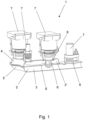
- Figure 1 shows a cross-section of an arrangement 1 with a housing 2 composed of two materially bonded housing parts 4, 5. Openings 6 are made in the housing 2, with functional elements 7 in the form of two switching valves and a check valve being arranged in the openings 6. The functional elements 7 are inserted into the openings 6 and connected to the housing 2 in a media-tight manner by means of an O-ring seal. Furthermore, openings are also made in the separating element 8 so that the functional elements 7 can extend through the separating element 8 and connect the channels 3, 3' to one another.
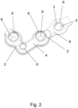
- FIG 2 shows in detail the housing 2 of the arrangement 1 according to Figure 1 , in which a housing part 4 does not extend completely over the housing 2.
- a flat separating element 8 is arranged between the housing parts 4, 5.
- a Housing part 4 does not completely cover the separating element 8, so that the separating element 8 also functions in sections as the outer wall of the housing 2. This design is particularly space-saving.
Landscapes
- Engineering & Computer Science (AREA)
- Physics & Mathematics (AREA)
- Mechanical Engineering (AREA)
- Thermal Sciences (AREA)
- General Engineering & Computer Science (AREA)
- Chemical Kinetics & Catalysis (AREA)
- Chemical & Material Sciences (AREA)
- Manufacturing & Machinery (AREA)
- Electrochemistry (AREA)
- General Chemical & Material Sciences (AREA)
- Fluid Mechanics (AREA)
- Cooling Or The Like Of Electrical Apparatus (AREA)
- Air-Conditioning For Vehicles (AREA)
- Control Of Temperature (AREA)
- Casings For Electric Apparatus (AREA)
Abstract
Description
- Die Erfindung betrifft eine Anordnung für einen Temperierkreislauf, umfassend ein Gehäuse, in welchem zumindest ein Kanal für den Transport von Temperiermedien ausgebildet ist.
- Eine derartige Anordnung ist beispielsweise aus der
US 2019/0039440 A1 bekannt. - Die dort gezeigte Anordnung findet in der Elektromobilität Einsatz, wo Klimatisierungseinrichtungen besonders hohen Anforderungen unterliegen. In der Elektromobilität besteht die Anforderung, dass nur ein beschränkter Bauraum zur Verfügung steht und die Klimatisierungseinrichtungen besonders kompakt ausgebildet sein müssen. Des Weiteren kann es erforderlich sein, neben dem Fahrgastinnenraum weitere Komponenten zu klimatisieren, beispielsweise die Elektromotoren, die Leistungselektronik, die Ladeeinheit und die elektrischen Speicherzellen.
- Elektrofahrzeuge haben einen optimalen Wirkungsgrad nur in einem begrenzten Temperaturspektrum, daher kann es erforderlich sein, in Abhängigkeit der klimatischen Bedingungen und der geforderten Leistung die an die Klimatisierungseinrichtung angeschlossenen Komponenten zu wärmen oder zu kühlen. Dies erfordert eine komplexe Ansteuerung der Komponenten und eine aufwendige Führung des Temperiermediums, sodass die Anordnungen mehrere Fluidkanäle aufweisen und mit mehreren Ventilen ausgerüstet sind. Aus dem Stand der Technik ist es hierzu bekannt, eine Rohranordnung in Form eines Gussteils bereitzustellen, in welchem mehrere Fluidkanäle ausgebildet sind. Derartige Gehäuse sind jedoch vergleichsweise aufwendig in der Herstellung.
- Die Temperierung, insbesondere die Kühlung, kann mittels eines Kältemittelkreislaufs erfolgen, in welchem ein Temperiermedium in Form eines Kältemittels, beispielsweise CO2 (R722), ein halogenierter Kohlenwasserstoff (R1234yf) oder ein Kohlenwasserstoff, beispielsweise Propan (R290) zirkuliert. Bei einem auf CO2 als Kältemittel basierenden Kältemittelkreislauf herrscht im Inneren des Kreislaufs mit 170 bar ein hoher Systemdruck. Die Temperaturen des Kältemittels auf der Basis von CO2 bewegen sich dabei zwischen -40 °C und 180 °C. Die Temperaturen bei einem auf einem Kohlenwasserstoff basierenden Kältemittel bewegen sich zwischen -20 °C und 160 °C bei Drücken von 1 bar bis 35 bar.
- Der Erfindung liegt die Aufgabe zugrunde, eine Anordnung für einen Temperierkreislauf bereitzustellen, der einfach und kostengünstig herstellbar ist.
- Diese Aufgabe wird mit den Merkmalen von Anspruch 1 gelöst. Auf vorteilhafte Ausgestaltungen nehmen die Unteransprüche Bezug.
- Die erfindungsgemäße Anordnung für einen Temperierkreislauf umfasst ein Gehäuse, in welchem zumindest ein Kanal für den Transport von Temperiermedien ausgebildet ist, wobei die Wandung des Gehäuses aus Blech ausgebildet ist.
- Durch die Ausgestaltung aus Blech ist das Gehäuse besonders kostengünstig herstellbar. Dabei kommen insbesondere Stahlbleche und Aluminiumbleche in Betracht. Bleche sind in einer Vielzahl von Stahl-, bzw. Aluminiumqualitäten und Wanddicken verfügbar und können besonders einfach umgeformt werden. Je nach Formgebung des Gehäuses entsteht dabei ein Gehäuse, welches hohen mechanischen und thermischen Belastungen standhält und dadurch auch für den Transport von CO2 als Kältemittel, bzw. Temperiermedium geeignet ist.
- Vorzugsweise weist das Gehäuse zumindest ein erstes Gehäuseteil und ein zweites Gehäuseteil auf. Die Gehäuseteile können separat hergestellt und anschließend zu dem Gehäuse gefügt werden. Dies ermöglicht die Ausgestaltung des Gehäuses mit einer sehr großen Formenvielfalt, sodass die Anordnung an den zur Verfügung stehenden Bauraum und die Anforderungen an die Temperierung optimal angepasst sein kann. Bei der Ausgestaltung mit mehr als zwei Gehäuseteilen können mit besonders einfachen Mitteln mehrere voneinander getrennte Kanäle ausgestaltet werden.
- Die Gehäuseteile können dabei insbesondere als Tiefziehteile oder Stanzteile ausgebildet sein. Bei dieser Ausgestaltung werden zunächst plattenförmige Blechabschnitte bereitgestellt und mittels Tiefziehen oder Stanzen in die gewünschte Form gebracht. In das Gehäuse können mehrere Öffnungen eingebracht sein, wobei insbesondere denkbar ist, dass die Öffnungen in einem Zug zusammen mit der Formgebung in die Gehäuseteile eingebracht werden. Dadurch reduzieren sich die für die Herstellung der Anordnung erforderlichen Fertigungsschritte und dadurch auch die Kosten. Insbesondere bei höheren Anforderungen an Toleranzen können die Gehäuseteile auch als Dreh- oder Frästeil ausgebildet sein. In diesem Zusammenhang ist insbesondere denkbar, dass zunächst die Gehäuseteile durch Tiefziehen erzeugt und anschließend die Öffnungen durch ein Dreh- oder Fräsverfahren in die Gehäuseteile eingebracht werden, um dort besonders genaue Passungen erzielen zu können. Werden die Gehäuseteile durch Stanzen erzeugt, können die Gehäuseteile durch Drehen oder Fräsen nachbearbeitet werden.
- Im Inneren des Gehäuses und/oder in den Öffnungen können Funktionselemente eingebracht sein. Funktionselemente sind beispielsweise Ventile, Rückschlagventile, Sensoren, Wärmetauscher, Expansionsventile oder dergleichen.
- Die Funktionselemente können formschlüssig und/oder stoffschlüssig in den Öffnungen der Gehäuseteile befestigt sein. Im Fall einer stoffschlüssigen Verbindung sind die Funktionselemente bereits durch die Verbindung mediendicht mit dem Gehäuse verbunden. Im Fall einer formschlüssigen Verbindung kann ein separates Dichtelement vorgesehen sein, beispielsweise ein O-Ring. Der in dem Gehäuseteil vorgesehene Dichtsitz für das Dichtelement kann dabei mittels Stanzen hergestellt sein. Hierbei ist vorteilhaft, dass zusätzliche Fertigungsschritte zur Herstellung eines Dichtsitzes entfallen können.
- In dem Gehäuse können mehrere Kanäle ausgebildet sein. Dadurch können mehrere Temperiermedien durch die Anordnung geführt werden oder ein Temperiermedium eines Kühlkreislaufs kann die Anordnung in verschiedenen Aggregatszuständen durchströmen. Denkbar ist, dass in einem ersten Kanal ein Transport von Kältemittel zwischen Kondensator und Verdampfer erfolgt; dort ist das Kältemittel flüssig. In dem zweiten Kanal kann ein Transport zwischen Verdampfer und Kompressor erfolgen, dort ist das Kältemittel gasförmig. Der Transport kann auch in Richtung weiterer Komponenten erfolgen. Denkbar ist auch, dass das Expansionsventil in dem Gehäuse ausgebildet und einem Kanal zugeordnet ist.
- Zwischen den Gehäuseteilen kann ein Trennelement aus Blech angeordnet sein. Vorzugsweise ist das Trennelement so ausgebildet, dass es die Kanäle separiert. Dabei kann das Blech gemäß einer einfachen und kostengünstigen Ausgestaltung flächig ausgebildet sein.
- Denkbar ist aber auch, dass das Trennelement dreidimensional geformt ist. Diese Formgebung kann auch durch ein Stanzverfahren erfolgen. Grundsätzlich ist ein aus Blech ausgebildetes Trennelement kostengünstig herstellbar und durch das Stanzverfahren kann ein Trennelement mit einer großen Formenvielfalt hergestellt werden. Neben dem Stanzverfahren ist auch denkbar, eine Formgebung mittels Tiefziehen durchzuführen.
- Es ist auch denkbar, dass das Trennelement als interner Wärmetauscher ausgebildet ist. Bei dieser Ausgestaltung ist vorteilhaft, wenn das Trennelement durch eine dreidimensionale Formgebung eine vergrößerte Oberfläche aufweist. Dies kann dadurch erfolgt sein, dass in das Trennelement Erhebungen und Vertiefungen eingebracht sind, die insbesondere in Form von Sicken vorliegen können.
- Durch den internen Wärmetauscher kann der zwischen Verdampfer und Kompressor verlaufende Abschnitt des Kältemittelkreislaufs thermisch mit einem zwischen Kondensator und Expansionsventil verlaufenden Abschnitt des Kältekreislaufs gekoppelt werden und durch den internen Wärmeaustausch kann der Wirkungsgrad des Kältemittelkreislaufs erhöht werden.
- Die Gehäuseteile können über eine Schweißverbindung oder eine Lötverbindung miteinander verbunden sein. Durch diese stoffschlüssige Verbindung sind die Gehäuseteile mediendicht und unlösbar miteinander verbunden.
- Die Gehäuseteile können alternativ über eine Schraubverbindung miteinander verbunden sein. Bei dieser Verbindung ist vorzugsweise zwischen den Gehäuseteilen zumindest ein Dichtelement angeordnet. Die Verbindung der Gehäuseteile über eine Schraubverbindung ist mit höheren Kosten verbunden als die Ausgestaltung einer stoffschlüssigen Verbindung. Vorteilhaft ist aber, dass die Gehäuseteile zerstörungsfrei demontierbar sind. Durch das zwischen den Gehäuseteilen angeordnete Dichtelement ergibt sich eine mediendichte Verbindung der Gehäuseteile.
- Die Anordnung kann eine Verteilstruktur einer Klimaanlage bilden. Dabei verteilt die Anordnung Temperiermedium zu den an die Anordnung angeschlossenen Komponenten. Durch Integration von Ventilen in Form von Schaltventilen, Proportionalventilen oder Rückschlagventilen kann der Transport zu den angeschlossenen Komponenten bedarfsweise erfolgen.
- Insbesondere ist denkbar, dass die Anordnung eine Verteilstruktur einer Klimaanlage eines Elektrofahrzeugs bildet. Dort kann die Verteilstruktur wahlweise den Innenraum und/oder die Komponenten des elektrischen Antriebs des Elektrofahrzeugs temperieren.
- Eine Ausgestaltung der Anordnung wird nachfolgend anhand der Figuren näher erläutert. Die Figuren zeigen, jeweils schematisch:
-
Fig. 1 eine Anordnung im Schnitt; -
Fig. 2 eine Anordnung in der Draufsicht. - Die Figuren zeigen eine Anordnung 1 für einen Temperierkreislauf. Die Anordnung 1 bildet einen Bestandteil eines Kältemittelkreislaufs einer Klimaanlage und fungiert dort als Verteilstruktur. Die Anordnung 1 umfasst ein Gehäuse 2, in welches zumindest ein Kanal 3 für den Transport von Temperiermedium eingebracht ist. Das Temperiermedium ist vorliegend ein Kältemittel, konkret CO2 (R744) oder ein halogenierter Kohlenwasserstoff (R1234yf). Die Anordnung 1 leitet das Kältemittel verschiedenen Komponenten des Kältemittelkreislaufs zu.
- Die Komponenten des Kältemittelkreislaufs können direkt an das Gehäuse 2 angeschlossen sein. In Abhängigkeit des zur Verfügung stehenden Bauraums und des Abstands der Komponenten können diese auch über Rohrleitungen an den Gehäuse 2 angeschlossen sein.
- Komponenten des Kältemittelkreislaufs sind dabei insbesondere Wärmetauscher, Verdampfer, Chiller, Kondensatoren, Gaskühler, Batteriekühlplatten, Kompressoren und Akkumulatoren. Diese Komponenten können mittels der Anordnung 1 wahlweise angesteuert und mit Kältemittel versorgt werden.
- Die Wandung des Gehäuses 2 ist aus Blech ausgebildet. Bei der vorliegenden Ausgestaltung ist das Blech ein Stahlblech mit einer Wanddicke von 3 mm. Vorzugsweise beträgt die Wanddicke des Gehäuses 2 zwischen 1 mm und 5 mm.
- Das Gehäuse 2 weist ein erstes Gehäuseteil 4 und ein zweites Gehäuseteil 5 auf, wobei die Gehäuseteile 4, 5 als Stanzteile ausbildet sind. In die Gehäuseteile 4, 5 und damit in das Gehäuse 2 sind mehrere Öffnungen 6 eingebracht. Die Formgebung der Gehäuseteile 4, 5 und das Einbringen der Öffnungen 6 erfolgt im Stanzverfahren in einem Arbeitsschritt. Zur Herstellung der Gehäuseteile 4, 5 wird zunächst ein plattenförmiges Blech bereitgestellt und mittels Stanzen geformt. Dabei erfolgt das Stanzen der äußeren Konturen der Gehäuseteile 4, 5, die dreidimensionale Formgebung und das Einbringen der Öffnungen 6 in die Gehäuseteile 4, 5 in einem Arbeitsschritt
- Bei der vorliegenden Ausgestaltung sind die Gehäuseteile 4, 5 über eine Schweißverbindung stoffschlüssig miteinander verbunden. Alternativ ist denkbar, die Gehäuseteile 4, 5 über eine Lötverbindung miteinander zu verbinden. In einer weiteren alternativen Ausgestaltung können die Gehäuseteile 4, 5 über eine Schraubverbindung miteinander verbunden sein. Zumindest im Fall der Schraubverbindung ist zwischen den Gehäuseteilen 4, 5 ein Dichtelement in Form einer Flachdichtung oder in Form einer auf ein Gehäuseteil aufgebrachten Dichtkontur angeordnet.
- Die Funktionselemente 7 umfassen Sensoren in Form von Temperatursensoren, Drucksensoren und Volumenstromsensoren sowie Ventile in Form von magnetischen Schaltventilen, Wegeventilen, Überdruckventilen und Rückschlagventilen.
- Zwischen den Gehäuseteilen 4, 5 ist ein Trennelement 8 aus Blech angeordnet. Das Trennelement 8 separiert zwei Kanäle 3, 3' voneinander. Demensprechend ermöglicht das Trennelement 8 die Anordnung mehrerer Kanäle 3, 3' innerhalb des Gehäuses 2.
- Das Trennelement 8 ist aus Blech, konkret aus Stahlblech ausgebildet und weist eine Wandstärke von 1 mm auf. Bei der vorliegenden Ausgestaltung sind in das Trennelement 8 Erhebungen und Vertiefungen in Form von Sicken eingebracht und das Trennelement 8 fungiert als interner Wärmetauscher. In einer alternativen Ausgestaltung ist das Trennelement 8 plattenförmig ausgebildet.
-
Figur 1 zeigt im Schnitt eine Anordnung 1 mit einem aus zwei stoffschlüssig miteinander verbundenen Gehäuseteilen 4, 5 zusammengesetzten Gehäuse 2. In das Gehäuse 2 sind Öffnungen 6 eingebracht, wobei in den Öffnungen 6 Funktionselemente 7 in Form von zwei Schaltventilen und einem Rückschlagventil angeordnet sind. Die Funktionselemente 7 sind in die Öffnungen 6 eingesteckt und mittels O-Ring-Dichtung mediendicht mit dem Gehäuse 2 verbunden. Des Weiteren sind auch in das Trennelement 8 Öffnungen eingebracht, so dass sich die Funktionselemente 7 durch das Trennelement 8 erstrecken und die Kanäle 3, 3' miteinander verbinden können. -
Figur 2 zeigt im Detail das Gehäuse 2 der Anordnung 1 gemäßFigur 1 , bei welchem sich ein Gehäuseteil 4 nicht vollständig über das Gehäuse 2 erstreckt. Zwischen den Gehäuseteilen 4, 5 ist ein flächig ausgebildetes Trennelement 8 angeordnet. Ein Gehäuseteil 4 deckt das Trennelement 8 nicht vollständig ab, so dass das Trennelement 8 abschnittsweise auch als äußere Wandung des Gehäuses 2 fungiert. Diese Ausgestaltung ist besonders platzsparend.
Claims (15)
- Anordnung (1) für einen Temperierkreislauf, umfassend ein Gehäuse (2), in welchem zumindest ein Kanal (3) für den Transport von Temperiermedien ausgebildet ist, dadurch gekennzeichnet, dass die Wandung des Gehäuses (2) aus Blech ausgebildet ist.
- Anordnung nach Anspruch 1, dadurch gekennzeichnet, dass das Gehäuse (2) zumindest ein erstes Gehäuseteil (4) und ein zweites Gehäuseteil (5) aufweist.
- Anordnung nach Anspruch 1 oder 2, dadurch gekennzeichnet, dass die Gehäuseteile (4, 5) als Tiefziehteile oder als Stanzteile ausgebildet sind.
- Anordnung nach einem der Ansprüche1 bis 3, dadurch gekennzeichnet, dass in das Gehäuse (2) mehrere Öffnungen (6) eingebracht sind.
- Anordnung nach Anspruch 4, dadurch gekennzeichnet, dass in den Öffnungen (6) Funktionselemente (7) angeordnet sind.
- Anordnung nach einem der Ansprüche 1 bis 5, dadurch gekennzeichnet, dass in dem Gehäuse (2) mehrere Kanäle (3, 3`) ausgebildet sind.
- Anordnung nach einem der Ansprüche 2 bis 6, dadurch gekennzeichnet, dass zwischen den Gehäuseteilen (4, 5) ein Trennelement (8) aus Blech angeordnet ist.
- Anordnung nach Anspruch 7, dadurch gekennzeichnet, dass das Trennelement (8) die Kanäle (3, 3`) separiert.
- Anordnung nach Anspruch 7 oder 8, dadurch gekennzeichnet, dass das Trennelement (8) als interner Wärmetauscher ausgebildet ist.
- Anordnung nach einem der Ansprüche 2 bis 9, dadurch gekennzeichnet, dass die Gehäuseteile (4, 5) über eine Schweißverbindung oder eine Lötverbindung miteinander verbunden sind.
- Anordnung nach Anspruch 10, dadurch gekennzeichnet, dass die Gehäuseteile (4, 5) mediendicht miteinander verbunden sind.
- Anordnung nach einem der Ansprüche 2 bis 9, dadurch gekennzeichnet, dass die Gehäuseteile (4, 5) über eine Schraubverbindung miteinander verbunden sind.
- Anordnung nach einem der Ansprüche 2 bis 11, dadurch gekennzeichnet, dass zwischen den Gehäuseteilen (4, 5) zumindest ein Dichtelement angeordnet ist.
- Verteilstruktur für den Transport von Temperiermedien, umfassend eine Anordnung (1) nach einem der vorherigen Ansprüche.
- Kältemittelkreislauf für ein Elektrofahrzeug, umfassend eine Verteilstruktur nach Anspruch 14.
Applications Claiming Priority (1)
| Application Number | Priority Date | Filing Date | Title |
|---|---|---|---|
| DE202023104914.1U DE202023104914U1 (de) | 2023-08-29 | 2023-08-29 | Anordnung für einen Temperierkreislauf |
Publications (2)
| Publication Number | Publication Date |
|---|---|
| EP4517242A2 true EP4517242A2 (de) | 2025-03-05 |
| EP4517242A3 EP4517242A3 (de) | 2025-03-12 |
Family
ID=92458281
Family Applications (1)
| Application Number | Title | Priority Date | Filing Date |
|---|---|---|---|
| EP24194909.8A Withdrawn EP4517242A3 (de) | 2023-08-29 | 2024-08-16 | Anordnung für einen temperierkreislauf |
Country Status (6)
| Country | Link |
|---|---|
| US (1) | US20250074159A1 (de) |
| EP (1) | EP4517242A3 (de) |
| JP (1) | JP2025036292A (de) |
| KR (1) | KR20250032937A (de) |
| CN (1) | CN119533009A (de) |
| DE (1) | DE202023104914U1 (de) |
Citations (1)
| Publication number | Priority date | Publication date | Assignee | Title |
|---|---|---|---|---|
| US20190039440A1 (en) | 2017-08-04 | 2019-02-07 | Tesla, Inc. | Technologies for manifolds |
Family Cites Families (4)
| Publication number | Priority date | Publication date | Assignee | Title |
|---|---|---|---|---|
| EP3026386B1 (de) * | 2014-06-13 | 2018-07-25 | Senior UK Limited | Plattenwärmetauscher und verfahren zur herstellung |
| CN215299360U (zh) * | 2018-05-30 | 2021-12-24 | 达纳加拿大公司 | 用于电池热调节的热管理系统和热交换器 |
| JP7033730B2 (ja) * | 2018-07-11 | 2022-03-11 | パナソニックIpマネジメント株式会社 | 冷却装置、電池温度調整システム及び車両 |
| DE202021104430U1 (de) * | 2021-08-18 | 2021-08-25 | Ti Automotive Technology Center Gmbh | Rohranordnung für eine Klimatisierungseinrichtung |
-
2023
- 2023-08-29 DE DE202023104914.1U patent/DE202023104914U1/de active Active
-
2024
- 2024-08-06 KR KR1020240104712A patent/KR20250032937A/ko not_active Ceased
- 2024-08-12 CN CN202411099405.5A patent/CN119533009A/zh active Pending
- 2024-08-16 EP EP24194909.8A patent/EP4517242A3/de not_active Withdrawn
- 2024-08-22 US US18/812,598 patent/US20250074159A1/en active Pending
- 2024-08-28 JP JP2024146433A patent/JP2025036292A/ja not_active Withdrawn
Patent Citations (1)
| Publication number | Priority date | Publication date | Assignee | Title |
|---|---|---|---|---|
| US20190039440A1 (en) | 2017-08-04 | 2019-02-07 | Tesla, Inc. | Technologies for manifolds |
Also Published As
| Publication number | Publication date |
|---|---|
| KR20250032937A (ko) | 2025-03-07 |
| EP4517242A3 (de) | 2025-03-12 |
| CN119533009A (zh) | 2025-02-28 |
| US20250074159A1 (en) | 2025-03-06 |
| DE202023104914U1 (de) | 2024-08-30 |
| JP2025036292A (ja) | 2025-03-14 |
Similar Documents
| Publication | Publication Date | Title |
|---|---|---|
| DE102020124471A1 (de) | Montageverteiler eines gebündelten integrierten wärmepumpenmoduls | |
| EP1459025B1 (de) | Vorrichtung zum austausch von wärme | |
| DE102018110370B4 (de) | Wärmetauscher für ein Fahrzeug | |
| DE102018108013A1 (de) | Vorrichtung zum Regeln eines Durchflusses und Verteilen eines Fluids in einem Fluidkreislauf | |
| DE102013219200A1 (de) | Kühleinrichtung für ein Batteriesystem, insbesondere eines Kraftfahrzeugs | |
| WO2018215358A1 (de) | Batteriesystem für ein elektrofahrzeug | |
| DE102016100192B4 (de) | Vorrichtung zur Wärmeübertragung | |
| DE112017007112T5 (de) | Kältemittelkreislaufvorrichtung | |
| WO2022258315A1 (de) | Heiz- und kühlmodul und verfahren | |
| DE102020202313A1 (de) | Wärmeübertrager | |
| DE102015111393A1 (de) | Vorrichtung zur Wärmeübertragung | |
| EP2293001A2 (de) | Wärmeübertrager mit integriertem Kältespeicher | |
| EP3853051A1 (de) | Modulare aufdachklimaanlage | |
| DE102010055388B4 (de) | Dekompressionsvorrichtung | |
| DE102020101031B4 (de) | Vorrichtung zum Regeln eines Durchflusses und Verteilen eines Fluids in einem Fluidkreislauf | |
| EP3964374A1 (de) | Rohranordnung für den transport von temperiermedien | |
| EP4517242A2 (de) | Anordnung für einen temperierkreislauf | |
| DE102023123709B4 (de) | Thermomanagement Modul | |
| DE102022104198A1 (de) | Wärmemanagementsystem | |
| DE102020101030B4 (de) | Vorrichtung zum Regeln eines Durchflusses und Verteilen eines Fluids in einem Fluidkreislauf | |
| DE102008038506A1 (de) | Kältekreislauf-Komponentenanordnung und Fahrzeugkühlsystem | |
| DE102022114810A1 (de) | Plattenanordnung für einen fluidstrom | |
| DE102005028510A1 (de) | Verstellbarer innerer Wärmeübertrager | |
| DE112024000193T5 (de) | Verteilerfluidmodul | |
| DE102024209401A1 (de) | Fluidverteilungsgehäuse, Thermomanagementsystem, Fahrzeug und Gebäude mit einem solchen Fluidverteilungsgehäuse |
Legal Events
| Date | Code | Title | Description |
|---|---|---|---|
| PUAI | Public reference made under article 153(3) epc to a published international application that has entered the european phase |
Free format text: ORIGINAL CODE: 0009012 |
|
| STAA | Information on the status of an ep patent application or granted ep patent |
Free format text: STATUS: THE APPLICATION HAS BEEN PUBLISHED |
|
| PUAL | Search report despatched |
Free format text: ORIGINAL CODE: 0009013 |
|
| AK | Designated contracting states |
Kind code of ref document: A2 Designated state(s): AL AT BE BG CH CY CZ DE DK EE ES FI FR GB GR HR HU IE IS IT LI LT LU LV MC ME MK MT NL NO PL PT RO RS SE SI SK SM TR |
|
| AK | Designated contracting states |
Kind code of ref document: A3 Designated state(s): AL AT BE BG CH CY CZ DE DK EE ES FI FR GB GR HR HU IE IS IT LI LT LU LV MC ME MK MT NL NO PL PT RO RS SE SI SK SM TR |
|
| RIC1 | Information provided on ipc code assigned before grant |
Ipc: F28F 27/02 20060101ALI20250204BHEP Ipc: H01M 10/6568 20140101ALI20250204BHEP Ipc: H01M 10/6556 20140101ALI20250204BHEP Ipc: H01M 10/625 20140101ALI20250204BHEP Ipc: H01M 10/613 20140101ALI20250204BHEP Ipc: F28F 3/14 20060101ALI20250204BHEP Ipc: F28D 9/00 20060101ALI20250204BHEP Ipc: F28D 7/00 20060101AFI20250204BHEP |
|
| STAA | Information on the status of an ep patent application or granted ep patent |
Free format text: STATUS: THE APPLICATION IS DEEMED TO BE WITHDRAWN |
|
| 18D | Application deemed to be withdrawn |
Effective date: 20250913 |