EP4517183A1 - Door for home appliance and home appliance including same - Google Patents
Door for home appliance and home appliance including same Download PDFInfo
- Publication number
- EP4517183A1 EP4517183A1 EP24196878.3A EP24196878A EP4517183A1 EP 4517183 A1 EP4517183 A1 EP 4517183A1 EP 24196878 A EP24196878 A EP 24196878A EP 4517183 A1 EP4517183 A1 EP 4517183A1
- Authority
- EP
- European Patent Office
- Prior art keywords
- lighting
- housing
- cover
- door
- disposed
- Prior art date
- Legal status (The legal status is an assumption and is not a legal conclusion. Google has not performed a legal analysis and makes no representation as to the accuracy of the status listed.)
- Pending
Links
Images














Classifications
-
- F—MECHANICAL ENGINEERING; LIGHTING; HEATING; WEAPONS; BLASTING
- F24—HEATING; RANGES; VENTILATING
- F24C—DOMESTIC STOVES OR RANGES ; DETAILS OF DOMESTIC STOVES OR RANGES, OF GENERAL APPLICATION
- F24C15/00—Details
- F24C15/02—Doors specially adapted for stoves or ranges
- F24C15/04—Doors specially adapted for stoves or ranges with transparent panels
-
- F—MECHANICAL ENGINEERING; LIGHTING; HEATING; WEAPONS; BLASTING
- F21—LIGHTING
- F21V—FUNCTIONAL FEATURES OR DETAILS OF LIGHTING DEVICES OR SYSTEMS THEREOF; STRUCTURAL COMBINATIONS OF LIGHTING DEVICES WITH OTHER ARTICLES, NOT OTHERWISE PROVIDED FOR
- F21V17/00—Fastening of component parts of lighting devices, e.g. shades, globes, refractors, reflectors, filters, screens, grids or protective cages
- F21V17/10—Fastening of component parts of lighting devices, e.g. shades, globes, refractors, reflectors, filters, screens, grids or protective cages characterised by specific fastening means or way of fastening
- F21V17/16—Fastening of component parts of lighting devices, e.g. shades, globes, refractors, reflectors, filters, screens, grids or protective cages characterised by specific fastening means or way of fastening by deformation of parts; Snap action mounting
- F21V17/164—Fastening of component parts of lighting devices, e.g. shades, globes, refractors, reflectors, filters, screens, grids or protective cages characterised by specific fastening means or way of fastening by deformation of parts; Snap action mounting the parts being subjected to bending, e.g. snap joints
-
- E—FIXED CONSTRUCTIONS
- E06—DOORS, WINDOWS, SHUTTERS, OR ROLLER BLINDS IN GENERAL; LADDERS
- E06B—FIXED OR MOVABLE CLOSURES FOR OPENINGS IN BUILDINGS, VEHICLES, FENCES OR LIKE ENCLOSURES IN GENERAL, e.g. DOORS, WINDOWS, BLINDS, GATES
- E06B3/00—Window sashes, door leaves, or like elements for closing wall or like openings; Layout of fixed or moving closures, e.g. windows in wall or like openings; Features of rigidly-mounted outer frames relating to the mounting of wing frames
- E06B3/70—Door leaves
-
- F—MECHANICAL ENGINEERING; LIGHTING; HEATING; WEAPONS; BLASTING
- F21—LIGHTING
- F21V—FUNCTIONAL FEATURES OR DETAILS OF LIGHTING DEVICES OR SYSTEMS THEREOF; STRUCTURAL COMBINATIONS OF LIGHTING DEVICES WITH OTHER ARTICLES, NOT OTHERWISE PROVIDED FOR
- F21V15/00—Protecting lighting devices from damage
- F21V15/01—Housings, e.g. material or assembling of housing parts
-
- F—MECHANICAL ENGINEERING; LIGHTING; HEATING; WEAPONS; BLASTING
- F21—LIGHTING
- F21V—FUNCTIONAL FEATURES OR DETAILS OF LIGHTING DEVICES OR SYSTEMS THEREOF; STRUCTURAL COMBINATIONS OF LIGHTING DEVICES WITH OTHER ARTICLES, NOT OTHERWISE PROVIDED FOR
- F21V19/00—Fastening of light sources or lamp holders
- F21V19/001—Fastening of light sources or lamp holders the light sources being semiconductors devices, e.g. LEDs
- F21V19/003—Fastening of light source holders, e.g. of circuit boards or substrates holding light sources
-
- F—MECHANICAL ENGINEERING; LIGHTING; HEATING; WEAPONS; BLASTING
- F21—LIGHTING
- F21V—FUNCTIONAL FEATURES OR DETAILS OF LIGHTING DEVICES OR SYSTEMS THEREOF; STRUCTURAL COMBINATIONS OF LIGHTING DEVICES WITH OTHER ARTICLES, NOT OTHERWISE PROVIDED FOR
- F21V19/00—Fastening of light sources or lamp holders
- F21V19/02—Fastening of light sources or lamp holders with provision for adjustment, e.g. for focusing
-
- F—MECHANICAL ENGINEERING; LIGHTING; HEATING; WEAPONS; BLASTING
- F21—LIGHTING
- F21V—FUNCTIONAL FEATURES OR DETAILS OF LIGHTING DEVICES OR SYSTEMS THEREOF; STRUCTURAL COMBINATIONS OF LIGHTING DEVICES WITH OTHER ARTICLES, NOT OTHERWISE PROVIDED FOR
- F21V21/00—Supporting, suspending, or attaching arrangements for lighting devices; Hand grips
-
- F—MECHANICAL ENGINEERING; LIGHTING; HEATING; WEAPONS; BLASTING
- F21—LIGHTING
- F21V—FUNCTIONAL FEATURES OR DETAILS OF LIGHTING DEVICES OR SYSTEMS THEREOF; STRUCTURAL COMBINATIONS OF LIGHTING DEVICES WITH OTHER ARTICLES, NOT OTHERWISE PROVIDED FOR
- F21V3/00—Globes; Bowls; Cover glasses
- F21V3/04—Globes; Bowls; Cover glasses characterised by materials, surface treatments or coatings
- F21V3/049—Patterns or structured surfaces for diffusing light, e.g. frosted surfaces
-
- F—MECHANICAL ENGINEERING; LIGHTING; HEATING; WEAPONS; BLASTING
- F21—LIGHTING
- F21V—FUNCTIONAL FEATURES OR DETAILS OF LIGHTING DEVICES OR SYSTEMS THEREOF; STRUCTURAL COMBINATIONS OF LIGHTING DEVICES WITH OTHER ARTICLES, NOT OTHERWISE PROVIDED FOR
- F21V33/00—Structural combinations of lighting devices with other articles, not otherwise provided for
- F21V33/0004—Personal or domestic articles
- F21V33/0044—Household appliances, e.g. washing machines or vacuum cleaners
-
- F—MECHANICAL ENGINEERING; LIGHTING; HEATING; WEAPONS; BLASTING
- F24—HEATING; RANGES; VENTILATING
- F24C—DOMESTIC STOVES OR RANGES ; DETAILS OF DOMESTIC STOVES OR RANGES, OF GENERAL APPLICATION
- F24C15/00—Details
- F24C15/008—Illumination for oven cavities
-
- F—MECHANICAL ENGINEERING; LIGHTING; HEATING; WEAPONS; BLASTING
- F25—REFRIGERATION OR COOLING; COMBINED HEATING AND REFRIGERATION SYSTEMS; HEAT PUMP SYSTEMS; MANUFACTURE OR STORAGE OF ICE; LIQUEFACTION SOLIDIFICATION OF GASES
- F25D—REFRIGERATORS; COLD ROOMS; ICE-BOXES; COOLING OR FREEZING APPARATUS NOT OTHERWISE PROVIDED FOR
- F25D23/00—General constructional features
- F25D23/02—Doors; Covers
- F25D23/028—Details
-
- F—MECHANICAL ENGINEERING; LIGHTING; HEATING; WEAPONS; BLASTING
- F25—REFRIGERATION OR COOLING; COMBINED HEATING AND REFRIGERATION SYSTEMS; HEAT PUMP SYSTEMS; MANUFACTURE OR STORAGE OF ICE; LIQUEFACTION SOLIDIFICATION OF GASES
- F25D—REFRIGERATORS; COLD ROOMS; ICE-BOXES; COOLING OR FREEZING APPARATUS NOT OTHERWISE PROVIDED FOR
- F25D27/00—Lighting arrangements
-
- E—FIXED CONSTRUCTIONS
- E05—LOCKS; KEYS; WINDOW OR DOOR FITTINGS; SAFES
- E05Y—INDEXING SCHEME ASSOCIATED WITH SUBCLASSES E05D AND E05F, RELATING TO CONSTRUCTION ELEMENTS, ELECTRIC CONTROL, POWER SUPPLY, POWER SIGNAL OR TRANSMISSION, USER INTERFACES, MOUNTING OR COUPLING, DETAILS, ACCESSORIES, AUXILIARY OPERATIONS NOT OTHERWISE PROVIDED FOR, APPLICATION THEREOF
- E05Y2800/00—Details, accessories and auxiliary operations not otherwise provided for
- E05Y2800/10—Additional functions
- E05Y2800/106—Lighting
-
- E—FIXED CONSTRUCTIONS
- E05—LOCKS; KEYS; WINDOW OR DOOR FITTINGS; SAFES
- E05Y—INDEXING SCHEME ASSOCIATED WITH SUBCLASSES E05D AND E05F, RELATING TO CONSTRUCTION ELEMENTS, ELECTRIC CONTROL, POWER SUPPLY, POWER SIGNAL OR TRANSMISSION, USER INTERFACES, MOUNTING OR COUPLING, DETAILS, ACCESSORIES, AUXILIARY OPERATIONS NOT OTHERWISE PROVIDED FOR, APPLICATION THEREOF
- E05Y2900/00—Application of doors, windows, wings or fittings thereof
- E05Y2900/30—Application of doors, windows, wings or fittings thereof for domestic appliances
- E05Y2900/308—Application of doors, windows, wings or fittings thereof for domestic appliances for ovens
-
- F—MECHANICAL ENGINEERING; LIGHTING; HEATING; WEAPONS; BLASTING
- F21—LIGHTING
- F21W—INDEXING SCHEME ASSOCIATED WITH SUBCLASSES F21K, F21L, F21S and F21V, RELATING TO USES OR APPLICATIONS OF LIGHTING DEVICES OR SYSTEMS
- F21W2131/00—Use or application of lighting devices or systems not provided for in codes F21W2102/00-F21W2121/00
- F21W2131/30—Lighting for domestic or personal use
- F21W2131/307—Lighting for domestic or personal use for ovens
-
- F—MECHANICAL ENGINEERING; LIGHTING; HEATING; WEAPONS; BLASTING
- F21—LIGHTING
- F21Y—INDEXING SCHEME ASSOCIATED WITH SUBCLASSES F21K, F21L, F21S and F21V, RELATING TO THE FORM OR THE KIND OF THE LIGHT SOURCES OR OF THE COLOUR OF THE LIGHT EMITTED
- F21Y2113/00—Combination of light sources
-
- F—MECHANICAL ENGINEERING; LIGHTING; HEATING; WEAPONS; BLASTING
- F21—LIGHTING
- F21Y—INDEXING SCHEME ASSOCIATED WITH SUBCLASSES F21K, F21L, F21S and F21V, RELATING TO THE FORM OR THE KIND OF THE LIGHT SOURCES OR OF THE COLOUR OF THE LIGHT EMITTED
- F21Y2115/00—Light-generating elements of semiconductor light sources
- F21Y2115/10—Light-emitting diodes [LED]
Definitions
- the present disclosure relates to Door for a home appliance.
- Home appliances storing target objects therein and including doors may be widely used.
- the home appliances may include storage spaces to store target objects in cabinets creating the external appearance thereof, and doors to open and close the storage spaces.
- a home appliance may include two or more storage spaces and two or more doors opening and closing respective storage spaces.
- a door of the home appliance may be formed opaque. Therefore, when the door closes the corresponding storage space, it is difficult for a user to check a target object stored in the storage space. To check the target object stored in the storage space in the home appliance equipped with the doors, it is essential to open the door
- a home appliance such as a refrigerator, an oven, and a clothes dryer
- heated air or cooled air in the home appliance may be discharged outward, thereby causing unnecessary energy loss.
- a home appliance such as a washing machine
- washing water may spill outward. Therefore, the door of the washing machine during a washing operation may remain locked so that the door is prevented from being opened accidentally during the washing operation.
- the door of some home appliances such as the cooking appliance, the washing machine, the dryer machine, etc. may include a window mounted to the door.
- the window When the window is mounted to the door, the state of the target object in the home appliance may be checked through the window.
- the window is mounted to the door of the home appliance, it is difficult to properly check a state of the target object when the environment of the home appliance is dark or at night.
- the home appliance may include a door equipped with a window, and a camera to project the inside space where the target object is stored. Even when the door is closed, the camera may capture the inside part of the storage space to provide the captured image to the user.
- the cooking appliance has a high temperature environment in the storage space, and the washing machine or the dryer machine has an environment with high humidity in the storage space, so the camera thereof may be easily damaged.
- a lighting device may include a lighting cover covering a light source such as an LED, protecting the light source, and diffusing light from the light source evenly.
- the lighting cover may be formed as a separate object made of a transparent material and then assembled with the lighting device.
- a separate fastener such as a screw should be used, thereby increasing the number of parts and the number of labor hours.
- the lighting cover may be assembled using a locking step structure or a stationary fit structure without a screw
- a coupling force for mounting the lighting cover increases, and thus the assemblability of the lighting cover is reduced, which is a problem.
- the lighting device when the lighting device includes a plurality of light sources, light emitted from the plurality of light sources may overlap in a predetermined region.
- the light overlapping as described above may only partially brighten the internal part of the storage space to reduce the lighting quality.
- This problem may be removed by diffusing light from the light source with a lighting cover formed of a translucent material such as an etching glass.
- the cover of a translucent material such as an etching glass, etc. has a problem reducing the overall light source illuminance.
- an objective of the present disclosure is to dispose a lighting device in a door where temperature and humidity conditions are better than a storage space of a home appliance to increase illuminance of the storage space.
- Another objective of the present disclosure is to cover a light source of a lighting device with a cover plate, and allow the cover plate to be easily mounted even without a separate fastener and to maintain a stable mounted state thereof.
- Yet another objective of the present disclosure is to prevent excessively high illuminance in a light-overlapping portion even with a plurality of light sources and to secure sufficiently high light amount with the plurality of light sources.
- a door for a home appliance of the present disclosure may include a door body disposed in front of a storage space of a home appliance, and a lighting device disposed at the door body.
- the lighting device may include a lighting housing with an installation space provided therein, a light source emitting light to the storage space, and a cover plate transmitting light from the light source.
- the lighting device is installed at the door body, not a main body of the home appliance. Specifically, the lighting device is surrounded by the lighting housing and the cover plate, so the lighting device is less affected by an internal environment of the home appliance, and durability of the lighting device may be improved.
- the door body is disposed in front of the storage space and includes a door frame in which a through part is provided at a central portion thereof.
- a door panel including a plurality of panels may be coupled to the door frame.
- a lighting device may be disposed between the plurality of panels. Since the lighting device is installed in the door, the lighting device is less affected by the internal environment of the home appliance, and the durability of the lighting device may be improved. Furthermore, in the present disclosure, the lighting device is disposed in the door facing the storage space, so it is easy to illuminate the entire part in the storage space using the lighting device.
- the lighting housing may include a first housing in which the light source is disposed, and a second housing in which the cover plate is disposed.
- the second housing may include a cover stopper supporting a first end portion of the cover plate
- the first housing may include a cover support arm supporting a second end portion of the cover plate opposite to the first end portion.
- the cover support arm may protrude from a surface of the first housing toward a surface of the second housing. Therefore, the cover support arm may support the end portion of the cover plate with assembly of the two housings.
- the cover holding parts may simultaneously support two different surfaces of the cover plate. Accordingly, the cover plate may not be separated in a direction toward the first housing.
- cover plate may be coupled to the pair of cover holding parts while sliding between the pair of cover holding parts. Accordingly, the cover plate may be easily assembled.
- the cover support arm may be disposed at a position farther from the second end portion of the cover plate than the temporary assembly step. Accordingly, the cover plate may be supported doubly.
- the first end portion of the cover plate may pass through the temporary assembly step, slide between the cover holding parts, and then be supported by the cover stopper.
- a length between the first end portion and the second end portion of the cover plate may be shorter than a length between the cover stopper and the temporary assembly step. Accordingly, high fastening force does not occur when the cover plate is assembled, and assemblability may be improved.
- the lighting mounting part may include a lighting angle adjusting part on which the lighting substrate is seated, and the lighting angle adjusting part may support the lighting substrate in an inclined direction.
- the lighting angle adjusting part may preset a light emitted angle of the lighting substrate and the light source.
- the lighting device may include a plurality of lighting parts, and the plurality of lighting parts may emit light in different directions. Accordingly, the lighting device may illuminate the wide space evenly in the storage space.
- the lighting device may include the plurality of lighting parts, and light emitted from the plurality of lighting parts may overlap at a central portion of the storage space.
- the stored object may become brighter, and use convenience and aesthetic feeling of the home appliance may be improved.
- the lighting device may include a plurality of lighting parts, and a plurality of cover plates respectively provided in the plurality of lighting parts may be disposed to be directed in different directions.
- the cover plates in the different directions may expand a light diffusion direction wider.
- a first cover plate of the plurality of cover plates may be provided at an angle rotated by a predetermined angle based on a shaft extending in a vertical direction that is a height direction of the door body with respect to a direction toward a front surface of a main body of the home appliance.
- a second cover plate of the plurality of cover plates may be provided at an angle rotated by a predetermined angle based on a shaft extending in a transverse direction that is a longitudinal direction of the lighting device with respect to a direction toward the front surface of the main body of the home appliance.
- the lighting device may include a plurality of lighting parts, and an image sensing device capturing an image of the storage space may be disposed between the plurality of lighting parts.
- the image sensing device may capture the internal part of the storage space with illuminance improved by the lighting device to provide a clear image.
- the plurality of lighting parts may be disposed at the same heights in the door, and the plurality of lighting parts may emit light at different vertical inclination angle. Accordingly, the plurality of lighting parts may emit light evenly to an upper portion and a lower portion of the storage space.
- the light source and the cover plate may be disposed to be directed in different directions.
- the cover plate may diffuse light from the light source in a direction different from the light emission angle of the light source.
- cover plate may be disposed in the installation space, and a part of the cover plate may be exposed outward of the installation space through a cover hole open in the lighting housing.
- a first surface of the cover plate facing an external part of the lighting housing and a second surface located opposite to the first surface and facing the light source may have different roughness from each other. Accordingly, light emitted from the light source may be diffused, and an excessively bright area may not occur.
- an roughness of the first surface may be higher than an roughness of the second surface. Then, reduction of a light amount of the light source may be minimized and light may be diffused.
- the second housing may include an inclined lighting guide surface that is provided at either portion of the cover hole with the cover hole as a center.
- the lighting guide surface may reflect light from the light source and guide a direction in which the light is emitted.
- the doors of a home appliance and the home appliance including the same according to the present disclosure have the following effects.
- the lighting device may be disposed in the door, not at the main body of the home appliance.
- the illuminance of the storage space can be obtained with the lighting device disposed in the door where the temperature and humidity are better than the storage space of the home appliance as described above, so the durability of the lighting device can be improved.
- the cover plate covering the light source may be disposed between the two housings (the first housing and the second housing).
- the two housings are assembled with each other, and thus the second end portion of the cover plate may be supported by the first housing.
- the two housings support the opposite end portions of the cover plate respectively. Therefore, while the cover plate is temporarily fixed to the second housing first, the two housings are assembled with each other, so that a secondary assembly of the cover plate may be naturally performed.
- the cover plate does not need to be completely assembled with either housing, so the assemblability of the cover plate is excellent, which is an advantage.
- the plurality of structures may support and fix the cover plate. Therefore, even though a separate fastener is not used, the lighting device can be firmly mounted in the door, so the number of parts and the number of labor hours of the assembly thereof can be reduced.
- the plurality of lighting parts may emit light in different directions. Accordingly, the plurality of lighting parts may emit light to a wide area evenly and light up the storage space.
- the angle adjusting part provided at the first housing may allow a mounting angle of a light source substrate to be preset in an inclined direction. Therefore, the fabricator does not need to perform separate work to adjust an angle of the light source, and assembly of the lighting device can be easily performed.
- the cover support arm supporting the second end portion of the cover plate may be disposed at a position farther from the second end portion of the cover plate than the temporary assembly step. Then, the temporary assembly step of the second housing and the cover support end of the first housing may support doubly the second end portion of the cover plate. Therefore, mounting stability of the cover plate can remain high, which is an effect.
- the cover support arm can support the second end portion of the cover plate, so it is safe to lower the height of the temporary assembly step.
- the temporary assembly step of a lower height may improve resistance (fastening force) when the cover plate is assembled, so the assemblability can be improved.
- the doors of a home appliance may be equipped with the image sensing device and the lighting device, so an image of the storage space may be captured while the illuminance of the storage space is increased.
- the user can obtain a clearer image of a target object stored in the storage space, so the use convenience and the product quality of the home appliance can be improved.
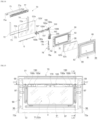
- FIG. 1 is a perspective view illustrating an embodiment of a home appliance according to the present disclosure.
- FIG. 2 is a perspective view illustrating the embodiment of the present disclosure with a separated side cover constituting the embodiment.
- FIG. 3 is a sectional view taken along line III-III' of FIG. 1 .
- FIG. 4 is a perspective view illustrating a lower unit constituting the embodiment of the present disclosure with a lighting illuminating.
- FIG. 5 is a plan view illustrating the lower unit constituting the embodiment of the present disclosure with the lighting illuminating.
- FIG. 6 is a side view illustrating the lower unit constituting the embodiment of the present disclosure with the lighting illuminating.
- FIG. 7 is a perspective view illustrating an upper storage space constituting the embodiment of the present disclosure.
- FIG. 1 is a perspective view illustrating an embodiment of a home appliance according to the present disclosure.
- FIG. 2 is a perspective view illustrating the embodiment of the present disclosure with a separated side cover constituting the embodiment.
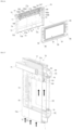
- FIG. 8 is a perspective view illustrating an upper door constituting the embodiment of the present disclosure.
- FIG. 9 is a sectional view taken along line IX-IX' of FIG. 8 .
- FIG. 10 is a sectional view enlarging and illustrating part A of FIG. 3 .
- FIG. 11 is a perspective view illustrating a lower door constituting the embodiment of the present disclosure.
- FIG. 12 is a perspective view illustrating the lower door constituting the embodiment of the present disclosure at a different angle from FIG. 11 .
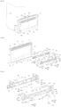
- FIG. 13 is an exploded perspective view illustrating main components of the lower door constituting the embodiment of the present disclosure.
- FIG. 14 is a perspective view illustrating, in greater detail than FIG. 13 , the main components of the lower door constituting the embodiment of the present disclosure.
- FIG. 15 is a rear view illustrating the lower door without a rear frame constituting the embodiment of the present disclosure.
- FIG. 16 is a perspective view illustrating configuration of a front frame part, an inner frame part, and a front panel among components of the lower door constituting the embodiment of the present disclosure.
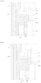
- FIG. 17 is a sectional view taken along line XVII-XVII' of FIG. 11 .
- FIG. 18 is a sectional view taken along line XVIII-XVIII' of FIG. 11 .
- FIG. 19 is a bottom view illustrating the lower door constituting the embodiment of the present disclosure without an image acquisition module.
- FIG. 20 is a bottom view illustrating the lower door constituting the embodiment of the present disclosure with the image acquisition module.
- FIG. 21 is a sectional view enlarging and illustrating part B of FIG. 20.
- FIG. 22 is a perspective view illustrating configuration of the front frame part, the front panel, the image acquisition module, and a connection module, among components of the lower door constituting the embodiment of the present disclosure.
- FIG. 23 is a sectional view illustrating an inner structure of the lower door on the basis of line XXIII-XXIII' of FIG. 22 .
- FIG. 24 is a sectional view illustrating the inner structure of the lower door on the basis of line XXIV-XXIV' of FIG. 22 .
- FIG. 25 is a sectional view illustrating the inner structure of the lower door on the basis of line XXV-XXV' of FIG. 22 .
- FIG. 22 is a perspective view illustrating configuration of the front frame part, the front panel, the image acquisition module, and a connection module, among components of the lower door constituting the embodiment of the present disclosure.
- FIG. 23 is a sectional view
- FIG. 26 is a perspective view illustrating a coupled state of the front frame part, the front panel, and the image acquisition module, among the components of the lower door constituting the embodiment of the present disclosure.
- FIG. 27 is a perspective view illustrating a structure of the lower door, a main wire, and a connection wire that constitute the embodiment of the present disclosure.
- FIG. 28 is a perspective view illustrating the image acquisition module constituting the embodiment of the present disclosure separated from the front panel.
- FIG. 29 is an exploded perspective view illustrating a first housing and a second housing of the image acquisition module constituting the embodiment of the present disclosure.
- FIG. 30 is a perspective view illustrating an image sensing device and a lighting device which are mounted to the first housing of the image acquisition module constituting the embodiment of the present disclosure.
- FIG. 31 is a plan view illustrating the image sensing device and the lighting device mounted to the first housing of the image acquisition module constituting the embodiment of the present disclosure.
- FIG. 32 is a plan view illustrating a connection wire disposed in the first housing of the image acquisition module constituting the embodiment of the present disclosure.
- FIG. 33 is an enlarged perspective view illustrating a structure of a wire holder provided in the first housing of the image acquisition module constituting the embodiment of the present disclosure.
- FIG. 34 is a plan view illustrating a structure of the image acquisition module constituting the embodiment of the present disclosure.
- FIG. 35 is an enlarged perspective view illustrating a structure of a fixation clip part constituting the embodiment of the present disclosure.
- FIG. 36 is a sectional view taken along line XXXVI-XXXVI' of FIG.
- FIG. 37 is a sectional view illustrating a second embodiment of the fixation clip part constituting the embodiment of the present disclosure.
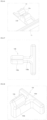
- FIG. 38 is an enlarged perspective view illustrating a first mounting structure of the first housing and the second housing of the image acquisition module constituting the embodiment of the present disclosure.
- FIG. 39 is a sectional view taken along line XXXIX-XXXIX' of FIG. 38 .
- FIG. 40 is an enlarged perspective view illustrating a second mounting structure of the first housing and the second housing of the image acquisition module constituting the embodiment of the present disclosure.
- FIG. 41 is a sectional view taken along line XLI-XLI' of FIG. 40 .
- FIG. 42 is an enlarged perspective view illustrating a third mounting structure of the first housing and the second housing of the image acquisition module constituting the embodiment of the present disclosure.
- FIG. 43 is a sectional view taken along line XLIII-XLIII' of FIG. 42 .
- FIG. 44 is a sectional view illustrating an assembling structure of the first housing and the second housing constituting the embodiment of the present disclosure.
- FIG. 45 is a plan view illustrating a structure of fastening hooks in the assembling structure of the first housing and the second housing constituting the embodiment of the present disclosure.
- FIG. 46 is a perspective view illustrating the structure of the fastening hooks in the assembling structure of the first housing and the second housing constituting the embodiment of the present disclosure.
- FIG. 47 is a plan view illustrating a structure of a fastening protrusion in the assembling structure of the first housing and the second housing constituting the embodiment of the present disclosure.
- FIG. 48 is a perspective view illustrating the structure of the fastening protrusion in the assembling structure of the first housing and the second housing constituting the embodiment of the present disclosure.
- FIGS. 49 to 50 are sequence views successively illustrating an assembling process of the assembling structure of the first housing and the second housing constituting the embodiment of the present disclosure.
- FIG. 51 is a perspective view illustrating the first housing equipped with the image sensing device constituting the embodiment of the present disclosure.
- FIG. 52 is a side view illustrating the first housing equipped with the image sensing device constituting the embodiment of the present disclosure.
- FIG. 53 is a sectional view taken along line LIII-LIII' of FIG. 34 .
- FIG. 54 is a sectional view enlarging and illustrating part C of FIG. 53 .
- FIG. 55 is a perspective view illustrating the second housing equipped with a protective cover of the image sensing device constituting the embodiment of the present disclosure.
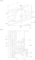
- FIG. 56 is a perspective view illustrating the first housing equipped with the lighting device constituting the embodiment of the present disclosure.
- FIG. 57 is a sectional view taken along line LVII-LVII' of FIG. 56 .
- FIG. 58 is a perspective view illustrating a structure of the second housing constituting the embodiment of the present disclosure.
- FIG. 59 is a perspective view illustrating the structure of the second housing constituting the embodiment of the present disclosure at a different angle from FIG. 58 .
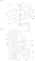
- FIG. 60 is a sectional view taken along line LX-LX' of FIG. 15 .
- FIGS. 62A to 62C are sectional views taken along line LXI-LXI' of FIG. 15 .
- FIG. 62 is a perspective view illustrating a cover plate exploded from FIG. 59 .
- FIG. 63 is a perspective view enlarging and illustrating the structure of the second housing and the cover plate constituting the embodiment of the present disclosure.
- FIG. 64 is a sectional view taken along line LXIV-LXIV' of FIG. 63 .
- FIG. 65 is a sectional view taken along line LXV-LXV' of FIG. 63 .
- FIG. 66 is a perspective view enlarging and illustrating the structure of the second housing and the cover plate constituting the embodiment of the present disclosure at a different angle from FIG. 63 .
- FIG. 67 is a concept view illustrating the cover plate coupled to the second housing constituting the embodiment of the present disclosure.
- FIG. 68 is a concept view expressed in a sectional form, the view illustrating the cover plate coupled to the second housing constituting the embodiment of the present disclosure.
- FIG. 69 is a sectional view taken along line LXIX-LXIX' of FIG. 34 .
- FIG. 70 is a penetration view illustrating an inner structure of the first housing, the second housing, and the lighting device constituting the embodiment of the present disclosure.
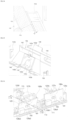
- FIG. 71 is a perspective view illustrating a second embodiment of the image acquisition module constituting the embodiment of the present disclosure.
- FIG. 72 is a perspective view illustrating a third embodiment of the image acquisition module constituting the embodiment of the present disclosure.
- FIG. 73 is a perspective view illustrating a fourth embodiment of the image acquisition module constituting the embodiment of the present disclosure.
- FIG. 74 is a perspective view illustrating a fifth embodiment of the image acquisition module constituting the embodiment of the present disclosure.
- FIG. 75 is a perspective view illustrating a sixth embodiment of the image acquisition module constituting the embodiment of the present disclosure.
- FIG. 71 is a perspective view illustrating a second embodiment of the image acquisition module constituting the embodiment of the present disclosure.
- FIG. 72 is a perspective view illustrating a third embodiment of the image acquisition module constituting the embodiment of the present disclosure.
- FIG. 76 is a perspective view illustrating a seventh embodiment of the image acquisition module constituting the embodiment of the present disclosure.
- FIG. 77 is a perspective view illustrating an eighth embodiment of the image acquisition module constituting the embodiment of the present disclosure.
- FIG. 78 is a perspective view illustrating a ninth embodiment of the image acquisition module constituting the embodiment of the present disclosure.
- FIG. 79 is a perspective view illustrating a tenth embodiment of the image acquisition module constituting the embodiment of the present disclosure.
- the present disclosure relates to Door for a home appliance (hereinafter, which will be referred to as "door”).
- the home appliance may include storage spaces therein.
- the doors may be disposed at the front side of the storage spaces to open and close the storage spaces.
- the front side may be a direction toward a user when the user is located in front of the home appliance.
- an X-axial direction may be a forward direction.
- a Y-axial direction may be a width direction of a door 50, 70.
- a Z-axial direction may be a height direction of the door 50, 70.
- the home appliance may be applied to the door 50, 70 of a home appliance such as a cooking appliance, a refrigerator, a freezer, a kimchi refrigerator, a plant cultivating apparatus, Styler ® , a washing machine, etc., and also be applied to doors of furniture or an entrance door.
- a home appliance such as a cooking appliance, a refrigerator, a freezer, a kimchi refrigerator, a plant cultivating apparatus, Styler ® , a washing machine, etc.
- the doors include two doors 50 and 70, but may also be applied to a home appliance equipped with one lower door 70.
- the present disclosure will describe an example in which two doors 50 and 70 are applied to a cooking appliance.
- a door at a relatively upper side of the two doors 50 and 70 may be called an upper door 50, and a door at a lower side may be called a lower door 70.
- the door 50, 70 may open and close a storage space 31, 41 of the home appliance and may acquire an image in the storage space 31, 41 by an image acquisition module 100. Furthermore, the door 50, 70 may increase the illuminance in the storage space 31, 41.
- the image acquisition module 100 may include an image sensing device 170 and a lighting device 180. The image acquisition module 100 may be provided in the door 50, 70, and the door 50, 70 will be described with a focus on the image acquisition module 100 below.
- the view illustrates a cooking appliance equipped with the door 50, 70.
- a main body 10 of the cooking appliance may be roughly shaped into a hexahedral form.
- the main body 10 of the cooking appliance may include two doors 50 and 70.
- the two doors 50 and 70 may be disposed at different heights.
- the two doors 50 and 70 may shield different storage spaces 31 and 41 respectively.
- FIG. 2 illustrates a separated state of a side cover 12 constituting the main body 10 of the cooking appliance.
- Two cabinets 30 and 40 may be disposed inside the inside space 13 at different heights.
- the two cabinets 30 and 40 may include the storage spaces 31 and 41 separated from each other.
- the inside space 13 may include one cabinet or three or more cabinets 30 and 40.
- the two cabinets 30 and 40 may be disposed transversely.
- Reference numeral 11 indicates a rear cover constituting the main body 10 of the cooking appliance.
- An upper panel 15 may be provided at an upper portion of the cooking appliance.
- the upper panel 15 may include an operating part 16.
- the operating part 16 may be used to operate functions of the cooking appliance and display a state of the cooking appliance.
- the upper panel 15 and the upper door 50 may be spaced apart from each other.
- a panel spacing D1 may be formed between the upper panel 15 and the upper door 50. External air may be introduced into the home appliance through the panel spacing D1, or internal air of the upper door 50 may be discharged.
- the upper panel 15 may be connected to a main wire W1.
- the main wire W1 may connect the operating part 16 to a main controller described below. Otherwise, the main wire W1 may connect the operating part 16 to the image acquisition module 100.
- the main wire W1 may be connected to a connection wire W2 described below through a connector module 200.
- the two cabinets 30 and 40 may be classified into a first cabinet 30 and a second cabinet 40.
- the first cabinet 30 and the second cabinet 40 may be disposed in the inside space 13 at different heights.
- the upper storage space 31 may be provided in the first cabinet 30, and the lower storage space 41 may be provided in the second cabinet 40.
- the first cabinet 30 and the second cabinet 40 may have different types of cooking structures.
- the first cabinet 30 may have one heat source, and the second cabinet 40 may have multiple heat sources.
- the first cabinet 30 may generate microwaves to cook a cooking object F, and the second cabinet 40 may include a convection heater or an induction heating type heat source.
- the upper door 50 may be disposed in front of the first cabinet 30, and the lower door 70 may be disposed in front of the second cabinet 40.
- the upper door 50 and the lower door 70 may be operated in a kind of pull-down method in which each upper end is vertically swung on a lower end thereof.
- the upper door 50 and the lower door 70 may be operated in a side swing method in which each door is opened sideways.
- a front surface 51 of the upper door 50 may have a structure allowing the upper storage space 31 to be visible.
- the front surface 51 of the upper door 50 has a glass panel structure, and a user can observe the inside part of the upper storage space 31 through the upper door 50.
- the front surface 51 of the upper door 50 may be made of dark materials or be coated with a separate film, thereby preventing the upper storage space 31 from being seen from the outside.
- Reference numeral 55 may indicate an upper handle 55 to open and close the upper door 50.
- the lower door 70 may be disposed below the upper door 50.
- the lower door 70 may be disposed in front of the second cabinet 40.
- the lower storage space 41 may be visible through a front surface of the lower door 70. The user can observe the inside of the lower storage space 41 through the front surface of the lower door 70.
- a door spacing D2 may be formed between the upper door 50 and the lower door 70.
- the door spacing D2 may be a space formed by spacing an upper end of the lower door 70 and a lower end of the upper door 50 from each other. Through the door spacing D2, external air may be introduced toward the main body 10 of the cooking appliance. On the other hand, air passing through the inside part of the lower door 70 may be discharged outward.
- the lower door 70 may include a window V
- the window V allows the lower storage space 41 to be visible from the outside space and may be made of a transparent material.
- the window V may be understood as a part of a second front panel G2a constituting the front surface of the lower door 70.
- the window V may be provided in a central portion of the second front panel G2a.
- an edge portion of the second front panel G2a may have a material with high surface roughness unlike the window V, or a separate opaque film may be applied to the edge portion of the second front panel G2a. Then, excluding the window V, the lower storage space 41 may not be visible through the edge portion of the second front panel G2a.
- the edge of the second front panel G2a corresponding to the outside part of the window V may be covered by a door frame 72, 77, 80, 90.
- the outside part of the window V may be the edge part of the second front panel G2a disposed around the edges of the window V with the window V as the center.
- the lower door 70 may be made of dark materials or coated with a separate film, thereby preventing the lower storage space 41 from being visible from the outside space.
- the lower door panel G2 described below may be omitted, and an opaque metal or nonmetal plate may constitute the front surface thereof. Also, in this case, the lower storage space 41 may not be visible from the outside space.
- FIG. 2 illustrates the image acquisition module 100 and the connector module 200 that are mounted inside the lower door 70.
- FIG. 2 illustrates the image acquisition module 100 and the connector module 200 indicating positions where the image acquisition module 100 and the connector module 200 are mounted inside the lower door 70, the image acquisition module 100 and the connector module 200 may not be visible from the front space of the cooking appliance. This is because the edge portion of the second front panel G2a excluding the window V is opaque, as described above.
- Reference numeral 75 indicates an upper handle 75 to open and close the lower door 70.
- FIG. 3 is a sectional view for the line III-III' of FIG. 1 .
- FIG. 3 illustrates the inner structure of the cooking appliance including the upper door 50 and the lower door 70.
- a plurality of spaces may be provided inside the cooking appliance.
- a machine chamber S1 may be disposed in an upper portion of the cooking appliance.
- Controllers 21 and 22 may be disposed in the machine chamber S1.
- a separate upper insulation space S2 partitioned from the machine chamber S1 may be provided below the machine chamber S1.
- a rear portion of the cooking appliance may also include an additional controller 23.
- Heating devices 35, 45, and 46 may be disposed at the rear portion of the cooking appliance and inside the cavities 30 and 40.
- the heating devices 35, 45, and 46 may heat the upper storage space 31 and the lower storage space 41.
- An upper motor 24 and an upper fan 25 may be disposed behind the upper storage space 31.
- the upper motor 24 and the upper fan 25 may discharge air into the upper storage space 31 to achieve convection of air inside the upper storage space 31.
- Reference numeral 38 indicates a tray disposed in the upper storage space 31.
- a lower motor 47 and a lower fan may be disposed behind the cooking appliance.
- the lower motor 47 and the lower fan may discharge air into the lower storage space 41 to achieve convection of air in the lower storage space 41.
- the lower motor 47 and the lower fan may circulate heated air.
- the lower storage space 41 may include a third heat source 46.
- the third heat source 46 may be disposed in front of the lower fan. The third heat source 46 may quickly raise the temperature in the lower storage space 41 with the second heat source 45.
- a cooling fan CF may be provided in the main body 10 of the cooking appliance.
- the cooling fan CF may circulate air in the machine chamber S1 to cool the cooking appliance.
- the cooling fan CF may be disposed behind the machine chamber S1.
- the cooling fan CF may circulate air into the upper door 50 and the lower door 70.
- the cooling fan CF allows air to be introduced into a lower flow path inlet I of the lower door 70 and then to pass the lower door 70 and the upper door 50 in order, thereby cooling the upper door 50 and the lower door 70.
- an air guide G may be provided at a lower portion of the lower door 70, and the flow path inlet I is formed in the air guide G so that external air may be introduced into the flow path inlet I.
- Reference numeral 73 indicates a bracket provided at a lower end of a front frame part 72 for mounting of the air guide G.
- the cooling fan CF may be operated to suck external air through the flow path inlet I disposed at the lower portion of the lower door 70 (direction of arrow 1).
- the sucked external air may rise along a second cooling flow path A2 formed between second insulation panels G2b and G2c and the second front panel G2a of the lower door 70 (direction of arrow 2).
- the rising external air may be discharged upward through a frame outlet 77a (referring to FIG. 17 ) formed in an upper frame part 77 described below.
- a part of the air passing through the lower door 70 may be discharged outward through a door spacing D2 (referring to FIG. 1 ) provided between the upper door 50 and the lower door 70. Furthermore, the remaining air is moved upward to be introduced into the upper door 50 (direction of arrow 3).
- the flow of air may cool the lower door 70, (ii) may cool the upper door 50, and (iii) may also cool the controllers 21, 22, and 25 disposed in the machine chamber S1.
- the cooling structure of the doors 50 and 70 using external air will be described below in detail.
- FIGS. 4 to 6 are views illustrating the second cabinet 40.
- the inside part of the lower storage space 41 provided in the second cabinet 40 may be captured by the image acquisition module 100.
- the lower storage space 41 may be captured by the image sensing device 170 constituting the image acquisition module 100, and the illuminance thereof may be increased by the lighting device 180 constituting the image acquisition module 100.
- FIGS. 4 to 6 are views illustrating light emitted by the lighting device 180.
- a central portion of the image acquisition module 100 may include the image sensing device 170.
- a plurality of lighting devices 180 may be disposed at both sides of the image sensing device 170 with the image sensing device 170 as the center. The plurality of lighting devices 180 increases the illuminance of the lower storage space 41 so that the image sensing device 170 acquires a clearer image.
- the plurality of lighting devices 180 is disposed toward the lower storage space 41 to emit light to the lower storage space 41.
- the plurality of lighting devices 180 may illuminate the lower storage space 41 at difference angles. Accordingly, the illuminance of the entire region of the lower storage space 41 may be uniformly increased. Specifically, the plurality of lighting devices 180 may illuminate an upper surface, a lower surface, and left and right surfaces of the lower storage space 41.
- a pair of first lighting parts 180a located relatively close to the image sensing device 170 may be disposed on the left and right sides of the image sensing device 170 with the image sensing device 170 as the center.
- a second lighting part 180b may be disposed outside each first lighting part 180a.
- a plurality of second lighting parts 180b is disposed at the left and right sides of the image sensing device 170 with the image sensing device 170 as the center.
- light radiation regions formed by the plurality of lighting devices 180 may be overlaid.
- the first lighting parts 180a emit lights while biasing in a central direction of the lower storage space 41 based on a transverse direction so that light may be overlaid in a constant region.
- the region where lights emitted by the pair of first lighting parts 180a are overlaid may be included in a central portion of the lower storage space 41. Accordingly, the illuminance of the cooking object F disposed on the central portion of the lower storage space 41 may be relatively higher than the surroundings.
- the region where the second lighting part 180b emits light and the transversal region where the first lighting part 180a emits light may overlap.
- the region where the first lighting part 180a emits light is partially overlaid with the region where the second lighting part 180b emits light, and the region where the illuminance is high may be provided in the central portion of the lower storage space 41 based on the transverse direction. Since the cooking object F is disposed in the central portion of the lower storage space 41 based on the transverse direction, the lighting device 180 may illuminate the cooking object F more brightly.
- first lighting part 180a and the second lighting part 180b emit light may be differently set.
- the first lighting part 180a may face the central portion of the lower storage space 41 relatively more than the second lighting part 180b.
- the first lighting part 180a emits light in a direction biasing the transversal central portion of the lower storage space 41 where the cooking object F in FIG. 5 is located, more than the second lighting part 180b. Accordingly, the first lighting part 180a and the second lighting part 180b emit light to a wider region based on the transverse direction to remove a shaded region.
- a direction of radiating light by the second lighting part 180b may be differently set from a direction of radiating light by the first lighting part 180a.
- the second lighting part 180b emits light in a direction further biasing to the bottom of the lower storage space 41 than the first lighting part 180a. Accordingly, the first lighting part 180a and the second lighting part 180b emit light to a wider region based on the vertical direction (Z-axial direction in FIG. 1 ) to remove a shaded region.
- the region where the second lighting part 180b emits light and the vertical region (Z-axial direction in FIG. 1 ) where the first lighting part 180a emits light may overlap.
- the region where the first lighting part 180a emits light is partially overlaid with the region where the second lighting part 180b emits light.
- the region where the illuminance is high may be provided in the central portion of the lower storage space 41 based on the vertical direction (Z-axial direction in FIG. 1 ). Since the cooking object F is disposed in the central portion of the lower storage space 41 based on the vertical direction (Z-axial direction in FIG. 1 ), the lighting device 180 may illuminate the cooking object F brightly.
- FIG. 7 illustrates the surroundings of an entrance of the upper storage space 31.
- a front cabinet frame 32 may be provided on a front surface of the upper storage space 31.
- the front cabinet frame 32 may include multiple communicating holes 33.
- the multiple communicating holes 33 may be a part where the air that has passed the inside part of the upper door 50 passes.
- Reference numeral 38 indicates a portion to which a part of a lower end of an upper door hinge 58 (referring to FIG. 9 ) is caught.
- FIG. 8 illustrates the rear structure of the upper door 50.
- An upper frame part 52 may be disposed in an upper portion of the upper door 50.
- the upper frame part 52 may cover an upper portion of a first frame part 61 and an upper portion of a second frame part 65 described below.
- the upper frame part 52 may include an upper outlet 52a, i.e., an outlet of the first cooling flow path A1, and a side outlet 52b.
- Reference numeral 52c may indicate a mounting hole that is open rearward of an upper end of the upper door 50.
- the upper outlet 52a provided in the upper frame part 52 may be an outlet through which the air passed through the upper door 50 is discharged outward.
- the side outlet 52b may be formed on a side surface of the upper frame part 52.
- Unmentioned reference numeral B1 indicates a fastener to assemble the upper door 50.
- the upper door 50 may have a frame formed by the first frame part 61 with the upper frame part 52.
- a window 61a, 65a may be formed in a central portion of the first frame part 61 having roughly a rectangular frame shape.
- a first insulation panel G1b, G1c may be disposed in the window 61a, 65a.
- the upper door 50 also includes a portion 51 through which the upper storage space 31 is visible.
- female protrusion parts 68 are respectively formed by being recessed and through which a part of a lower end of the first hinge 58 protrudes.
- Reference numeral 69 indicates a portion to which a hook (not shown) of the first cabinet 30 is securely caught when the upper door 50 is closed.
- FIG. 9 illustrates the internal structure of the upper door 50.
- the upper door 50 may include the first front panel G1a and two first insulation panels G1b and G1c.
- the first front panel G1a and the first insulation panels G1b and G1c may be made of glass materials, respectively.
- the first front panel G1a and the first insulation panels G1b and G1c are made of transparent or translucent materials, so the central portion thereof may have the portion 51 through which the upper storage space 31 is visible.
- a frame of the upper door 50 may be composed of multiple parts. As shown in FIG. 9 , the second frame part 65 may be provided inside the upper frame part 52 and the first frame part 61. The two first insulation panels G1b and G1c may be disposed between the first frame part 61 and the second frame part 65. A gap between the two first insulation panels G1b and G1c is maintained in a vacuum, thereby increasing insulation performance.
- air introduced into a lower portion of the upper door 50 may flow along the first cooling flow path A1 formed between the first insulation panel G1b, G1c and the first front panel G1a.
- at least a part of the air introduced into the lower portion of the upper door 50 may be air passing through the lower door 70 to be discharged upward (referring to FIG. 3 ).
- the air passing through the first cooling flow path A1 may be discharged upward through the upper outlet 52a formed on an upper end portion of the upper door 50.
- FIG. 10 enlarges and illustrates the part A of FIG. 3 .
- the air passing through the inside part of the upper door 50 may be discharged upward through the upper outlet 52a formed in the upper frame part 52.
- a part of the discharged air may be discharged forward through the panel spacing D1 (in a leftward direction based on FIG. 10 , referring to the arrow 1).
- the remaining air of the discharged air may be discharged rearward, i.e., rearward of the cooking appliance (at 2 o'clock based on FIG. 10 , referring to the arrow 2).
- the rearward discharged air may be introduced into the machine chamber S1 through the communicating holes 33 of the front cabinet frame 32, thereby cooling the inside part of the machine chamber S1.
- reference numeral 55a indicates a bracket to fix the upper handle 55 to the second frame part 65.
- reference numeral 56 indicates a first panel spacer that spaces the two first insulation frames from each other and fixes the first insulation frames to the inside part of the upper door 50.
- FIGS. 11 and 12 illustrate the lower door 70 when viewed from the front side and the rear side of the home appliance.
- the front surface of the lower door 70 may have a flat structure.
- the surface of the second front panel G2a may constitute the front surface of the lower door 70.
- the window V may be provided in the central portion of the front surface of the lower door 70.
- the window V may be a portion made of a transparent or translucent material so that the lower storage space 41 may be observed from the outside space.
- a part of the central portion of the second front panel G2a may be the window V
- the window V is not formed into a separate object from the second front panel G2a and may be a part of the second front panel G2a.
- the image acquisition module 100 may be disposed in the internal portion of the lower door 70.
- the image acquisition module 100 may acquire an inside image of the lower storage space 41 through the window V of the lower door 70 and display or transmit the image to the user.
- FIG. 11 the image acquisition module 100 disposed in the internal portion of the lower door 70 is illustrated in an outward exposed state.
- FIG. 11 illustrates the image acquisition module 100 in an exposed state to express a location where the image acquisition module 100 is disposed.
- the image acquisition module 100 may be disposed in a direction toward the lower storage space 41 (in a rearward direction based on FIG. 11 ).
- the image acquisition module 100 may be disposed at a portion in the lower door 70, and the portion is located outside the window V
- the outside means a portion enclosing the edges of the window V.
- the image acquisition module 100 may be disposed in an installation region T1 to T4 disposed outside the edges of the window V.
- FIG. 11 illustrates that most part of the image acquisition module 100 is disposed in an upper portion of the window V.
- the image acquisition module 100 may be disposed at the left and right portions of the window V or a lower portion thereof.
- a frame of the lower door 70 may be formed by the door body.
- the door body may include a lower door frame 72, 77, 80, 90 and the lower door panel G2.
- the door body may have roughly a hexahedral structure when the lower door frame 72, 77, 80, 90 and the lower door panel G2 are assembled.
- the lower door frame 72, 77, 80, 90 may include multiple frame parts.
- the lower door frame 72, 77, 80, 90 may include the front frame part 72, a rear frame part 80, an inner frame part 90, and the upper frame part 77.
- the frame parts may be coupled to each other to provide one lower door frame 72, 77, 80, 90.
- the "front" may be the front side of the lower door 70 (left side based on FIG. 11 ).
- the front frame part 72 may be disposed at the front part of the lower door frame 72, 77, 80, 90. More specifically, the front frame part 72 may form a front frame of the lower door frame 72, 77, 80, 90.
- a pair of front side plates 72a may be provided at both sides of the front frame part 72.
- a front lower plate 72b may connect the pair of front side plates 72a to each other while being located therebetween.
- the front side plates 72a and the front lower plate 72b are connected to each other to form roughly a "U" shape.
- a front opening 72c may be provided between the front side plates 72a and the front lower plate 72b.
- the front opening 72c may be an empty space open in a longitudinal direction.
- the second front panel G2a constituting the lower door panel G2 (referring to FIG. 18 ) may be disposed in the front opening 72c. It may be understood that an open portion of the front opening 72c is filled with the second front panel G2a.
- the region of the lower door panel G2 is wider than the region of the second front opening 72c, so a part of the front side plates 72a and a part of the front lower plate 72b may be stacked with the second front panel G2a, respectively.
- FIG. 13 illustrates the second front panel G2a stacked with the front frame part 72.
- the second front panel G2a may be disposed at one side.
- the upper handle 75 may be disposed at the opposite side of the second front side plates 72a.
- a separate fastener passes through the second front side plates 72a and a panel fastening hole G2a' of the second front panel G2a and then may be fastened to a handle assembly part 75a of the upper handle 75.
- the image acquisition module 100 is disposed on the second front panel G2a.
- the image acquisition module 100 may be adhered to a rear surface of the second front panel G2a, the surface facing the lower storage space 41. More specifically, a partial surface of a front surface of the image acquisition module 100 and a partial surface of a rear surface of the second front panel G2a may be adhered to each other.
- K1 and K2 indicate regions where the front surface of the image acquisition module 100 and the rear surface of the second front panel G2a adhere to each other.
- the rear panel G2c of the second insulation panels G2b and G2c constituting the rear surface of the lower door 70 may be exposed toward the lower storage space 41.
- the rear panel G2c may also include a window V.
- the window V of the rear panel G2c and the window V of the second front panel G2a are successively disposed at a predetermined distance therebetween and assigned with the same reference numeral. Although no reference numeral is assigned, in the second insulation panels G2b and G2c, the inner panel G2b unexposed outward of the lower door 70 may also have a window V
- the lower door panel G2 may include 3 panels in total.
- the 3 panels include the second front panel G2a disposed at the foremost side, the inner panel G2b disposed in the lower door 70, and the rear panel G2c disposed at the rearmost side.
- the second front panel G2a is exposed forward (front side of the home appliance the main body 10, X-axial direction of FIG. 1 ), and the rear panel G2c is exposed rearward opposite to the second front panel G2a (rear side toward the lower storage space 41).
- the inner panel G2b and the rear panel G2c may constitute the second insulation panels G2b and G2c.
- the inner panel G2b and the rear panel G2c may be stacked to each other at a constant distance.
- an empty space between the inner panel G2b and the rear panel G2c becomes a vacuum, thereby increasing insulation performance.
- the second insulation panels G2b and G2c may include only the rear panel G2c without the inner panel G2b.
- Reference numeral 76 indicates a second panel spacer 76 disposed between the inner panel G2b and the rear panel G2c to maintain a distance therebetween.
- the installation region T1 to T4 may be provided between the second front panel G2a and the second insulation panels G2b and G2c.
- the installation region T1 to T4 is provided in an empty space between the second front panel G2a and the second insulation panels G2b and G2c.
- the installation region T1 to T4 may be a portion where the image acquisition module 100 and the connector module 200 are disposed.
- the second cooling flow path A2 may also be provided between the second front panel G2a and the second insulation panels G2b and G2c.
- the second cooling flow path A2 may be the entire space between the second front panel G2a and the second insulation panels G2b and G2c.
- the installation region T1 to T4 may be disposed outside the window V with the window V as the center. Therefore, the second cooling flow path A2 is wider than the installation region T1 to T4, and it may be understood that the installation region T1 to T4 constitutes a part of the second cooling flow path A2.
- Air may flow in the lower door panel G2 through the second cooling flow path A2.
- the second cooling flow path A2 may be a flow space A2 in which air flows.
- the installation region T1 to T4 is indicated.
- the installation region T1 to T4 is a portion where the image acquisition module 100 and the connector module 200 are disposed, and a dotted line in FIG. 13 is expressed to help understand the installation region T1 to T4.
- the installation region T1 to T4 is expressed on a surface of the second front panel G2a.
- the installation region T1 to T4 may be provided between the plurality of panels, specifically between the second front panel G2a and the second insulation panels G2b and G2c.
- the upper frame part 77 corresponds to a portion of an upper end of a rear surface of the second front panel G2a, and a portion of the installation region T1 to T4 may be formed at a portion that is not covered by the upper frame part 77. More specifically, in the installation region T1 to T4, the first installation region T1, T3 may be provided at a lower portion of the upper frame part 77 that is not covered by the upper frame part 77.
- the installation region T1 to T4 may include (i) the first installation region T1, T3 formed in a first direction along an edge of the window V, and (ii) a second installation region T2, T4 formed in a second direction different from the first direction along an edge of the window V
- the first direction is a transverse direction (a transverse width direction of the lower door 70, and Y-axial direction of FIG. 1 )
- the second direction is a vertical direction (a height direction of the lower door 70, Z-axial direction of FIG. 1 ).
- the first installation region T1, T3 may be formed at each of an upper portion T1 and a lower portion T3 of the window V on the basis of the window V
- the second installation region T2, T4 may be formed at either side portion of the window V on the basis of the window V
- the installation region T1 to T4 may be divided into (i) the upper region T1 provided at the upper portion of the window V, (ii) the right region T2 provided at the right portion of the window V, (iii) the lower region T3 provided at the lower portion of the window V, and (iv) the left region T4 provided at the left portion of the window V
- the division is based on FIG. 16 .
- the first installation region T1, T3 and the second installation region T2, T4 may be connected to each other. Opposite end portions of the first installation region T1, T3 and the opposite end portions of the second installation region T2, T4 are connected to each other. Accordingly, the installation region T1 to T4 may be formed in connected spaces. Then, the image acquisition module 100 and the connector module 200 may be disposed to pass through the plurality of installation regions T1 to T4. In the embodiment, a part of the image acquisition module 100 is disposed in the first installation region T1, T3. The remaining part of the image acquisition module 100 is disposed in the second installation region T2, T4 connected to the first installation region T1, T3. In the embodiment, the connector module 200 is disposed in the second installation region T2, T4.
- At least a part of the installation region T1 to T4 may be provided at a region where a part of the lower door frame 72, 77, 80, 90 covers a rear surface of the second front panel G2a.
- the rear frame part 80 covers a part of the image acquisition module 100.
- covering, by the rear frame part 80, a part of the image acquisition module 100 is based on the rear side of the lower door 70, i.e., a direction from the inside space of the lower storage space 41 to the rear surface of the lower door 70 when the lower door 70 is closed.
- the image sensing device 170 and the lighting device 180 constituting the image acquisition module 100 are exposed through a rear through part 81 of the rear frame part 80.
- a part of the image acquisition module 100 corresponding to the image sensing device 170 and an upper portion of the lighting device 180 may be covered by the rear frame part 80.
- FIG. 15 it is expressed that the lighting device 180 is covered by the cover plate 190 and only the cover plate 190 is visible.
- the image sensing device 170 and the lighting device 180 may not be exposed through the window V Specifically, in the case in which the lower door 70 is opened and closed in a pull-down method, based on opening and closing angles, the image sensing device 170 and the lighting device 180 may also be covered by the rear frame part 80.
- the image acquisition module 100 is disposed in the first installation region T1, T3, and the connection wire W2 for allowing signal transmission and power supply between the image acquisition module 100 and the main controller may be disposed in the second installation region T2, T4.
- the second front panel G2a may be divided into the window V, and an edge part disposed around the edges of the window V.
- the installation region T1 to T4 may be provided at a rear surface of the edge part.
- the edge part may be processed to be opaque. Accordingly, the installation region T1 to T4 provided at a lower surface of the edge part may not be exposed from the front side of the lower door 70, i.e., from the front side of the cooking appliance.
- the edge part may be formed by etching a part of the second front panel G2a to increase the surface roughness, by being coated with a separate film, or may be treated opaque in a painting process.
- the upper frame part 77 may be disposed above the second front opening 72c.
- the upper frame part 77 may cover a part of the second front panel G2a.
- the image acquisition module 100 described below may be fixed to the upper frame part 77.
- the frame outlet 77a may be open in the upper frame part 77.
- the frame outlet 77a may be an outlet through which air passing through the second cooling flow path A2 formed in the lower door 70 is discharged outward.
- the frame outlet 77a faces a lower surface of the upper door 50, so the air discharged through the frame outlet 77a may be naturally transferred to the first cooling flow path A1 through the lower portion of the upper door 50.
- the frame outlet 77a is provided opposite to an inlet I of the second cooling flow path A2 and may be an outlet of the second cooling flow path A2.
- the frame outlet 77a may be connected to the installation region T1 to T4 as described below.
- the lower door 70 may include a lower door hinge 78.
- the lower door hinge 78 is expressed to be mounted in the lower door 70.
- a hinge holding arm 78a may protrude on the lower door hinge 78.
- the hinge holding arm 78a passes through an inner hinge passage part 98 of the inner frame part 90 and a rear hinge passage part 88 of the rear frame part 80 in order, then may be caught by and fixed to the main body 10 of the cooking appliance.
- Reference numeral 79 is a hinge spring 79 and may be fitted over a spring guide 78b of the lower door hinge 78.
- the front frame part 72 may be disposed at one side.
- the inner frame part 90 and the rear frame part 80 may be disposed at the opposite side.
- the inner frame part 90 and the rear frame part 80 are spaced apart from each other (i) to form an insulation space therebetween, and (ii) to fix the second insulation panels G2b and G2c.
- the inner frame part 90 is disposed between the rear frame part 80 and the front frame part 72, thereby being unexposed outward.
- the rear frame part 80 may be roughly formed in a rectangular frame shape. When the lower door 70 is closed, the rear frame part 80 may face a front surface of the lower storage space 41.
- the rear through part 81 may be open on a central portion of the rear frame part 80.
- the rear through part 81 may have a longitudinally open structure so that the internal space of the lower storage space 41 may be visible through the window V.
- Rear side plates 82 may be provided at side surfaces of the rear frame part 80.
- the rear side plates 82 may overlap with the front side plates 72a.
- the rear frame part 80 may include a rear bead part 87 around the surroundings of the rear through part 81.
- Reference numeral 88 is the rear hinge passage part 88 through which the hinge holding arm 78a of the lower door hinge 78 passes.
- the rear frame part 80 may cover a part of the image acquisition module 100. More specifically, the image sensing device 170 and the lighting device 180 constituting the image acquisition module 100 may be exposed through the rear through part 81 rearward, i.e., toward the lower storage space 41 (based on closed state). However, a part of the image acquisition module 100 which corresponds to upper portions of the image sensing device 170 and the lighting device 180 may be covered by the rear frame part 80. Accordingly, even when the user opens the lower door 70, remaining parts excluding the image sensing device 170 and the lighting device 180 may not be exposed through the window V
- the inner frame part 90 may be coupled to the rear frame part 80.
- the rear frame part 80 and the inner frame part 90 may be coupled to each other by a separate frame fastener B2 (referring to FIG. 18 ).
- a separate frame fastener B2 referring to FIG. 18 .
- the inner frame part 90 When the lower door 70 is closed, the inner frame part 90 may be stood vertically (Z-axial direction of FIG. 1 ) at a distance from the rear frame part 80.
- An inner through part 91 may be open on a central portion of the inner frame part 90.
- Inner side plates 92 may be provided at side surfaces of the inner frame part 90.
- the inner side plates 92 may overlap with the front side plates 72a and the rear side plates 82.
- the inner frame part 90 may include an inner bead part 97 which is provided around the circumference of the inner through part 91.
- Reference numeral 98 is the inner hinge passage part 98 through which the hinge holding arm 78a of the lower door hinge 78 passes.
- the inner frame part 90 may include a deformation prevention part 99.
- the deformation prevention part 99 may have a bead structure protruding in a direction from the inner frame part 90 toward a rear surface of the front frame part 72. More specifically, the deformation prevention part 99 may protrude in a direction facing a support protrusion 149 provided on the image acquisition module 100.
- the deformation prevention part 99 may protrude to a location spaced apart at a predetermined distance from the support protrusion 149.
- a terminal end portion of the deformation prevention part 99 and a surface of the support protrusion 149 are spaced apart from each other, vibrations usually generated in an operation process of the second door 70 may be prevented from being transmitted toward the image acquisition module 100 and durability of the image sensing device 100 may be improved.
- the deformation prevention part 99 may prevent the module housing 110, 140 from being excessively deformed in contact with the support protrusion 149.
- the deformation prevention part 99 may be disposed in the installation region T1 to T4.
- the support protrusion 149 and the deformation prevention part 99 may protrude toward each other respectively on facing surfaces of the image acquisition module 100 and the inner frame part 90.
- the protruding length of the deformation prevention means may be reduced.
- the deformation prevention part 99 may be provided on each end of the inner frame part 90. Then, when the image acquisition module 100 is deformed by heat, both ends of the image acquisition module 100 which are portions with the most bending may be supported by respective deformation prevention parts 99. Therefore, the deformation of the image acquisition module 100 may be efficiently prevented.
- the image sensing device 170 and the lighting device 180 provided at the image acquisition module 100 may be disposed between the plurality of deformation prevention parts 99. Then, the deformation prevention parts 99 may support both end portions of the image acquisition module 100 with the image sensing device 170 and the lighting device 180, i.e., heater elements, located therebetween. Therefore, even when the image acquisition module 100 is deformed, the image acquisition module 100 may be supported efficiently.
- Each deformation prevention part 99 may protrude in the longitudinal direction in which the plurality of panels are stacked to each other. In other words, it may be understood that each deformation prevention part 99 protrudes in a direction of reducing the second cooling flow path A2. Since the second cooling flow path A2 may be an empty space and provide an empty space where the image acquisition module 100 may be deformed, the deformation prevention part 99 protrudes in the direction of reducing the second cooling flow path A2 so that deformation of the image acquisition module 100 may be prevented efficiently.
- the second door 70 may include the deformation prevention part 99 or the support protrusion 149.
- the image acquisition module 100 includes the support protrusion 149, and the deformation prevention part 99 may be omitted in the inner frame part 90.
- the length of the support protrusion 149 may be formed longer than the length of the support protrusion 149 of a previous embodiment (referring to FIG. 61A ).
- the support protrusion 149 is omitted in the image acquisition module 100, and the inner frame part 90 may include the deformation prevention part 99.
- the length of the deformation prevention part 99 may be formed longer than the length of the deformation prevention part 99 of the previous embodiment (referring to FIG. 61A ).
- the inner frame part 90 may include the support protrusion 149, and the image acquisition module 100 may include the deformation prevention part 99.
- the inner frame part 90 may include the plurality of deformation prevention parts 99.
- the deformation prevention parts 99 may be provided on the left and right portions of the inner through part 91, respectively. More specifically, each deformation prevention part 99 may be provided on a portion corresponding to a corner of the inner through part 91 and provided at a disconnected portion of the inner bead part 97.
- the two deformation prevention parts 99 may support the support protrusions 149 disposed at both end portions of the image acquisition module 100, respectively. The structure of the deformation prevention part 99 and the support protrusion 149 will be described below again.
- FIG. 17 a sectional view of the lower door 70 is illustrated.
- the view illustrates the lower door panel G2 fixed among the front frame part 72, the rear frame part 80, and the inner frame part 90.
- the second front panel G2a may be in close contact with a surface of the front frame part 72.
- the image acquisition module 100 may be disposed on the surface of the second front panel G2a.
- the image acquisition module 100 may be disposed in the first installation region T1, T3 that is formed in an upper end portion of the second front panel G2a and a lower end portion of the upper frame part 77.
- the second cooling flow path A2 may be formed between the second front panel G2a and the inner panel G2b of the second insulation panels G2b and G2c.
- the second cooling flow path A2 may be the entire space between the second front panel G2a and the inner panel G2b.
- the arrow of FIG. 17 indicates a flow direction of external air passing through the second cooling flow path A2.
- the upper end portion of the second cooling flow path A2 includes the frame outlet 77a of the upper frame part 77, so an air outlet may be formed.
- the installation region T1 to T4 may be disposed outside the window V with the window V as the center. Therefore, the second cooling flow path A2 is wider than the installation region T1 to T4, and it may be understood that the installation region T1 to T4 constitutes a part of the second cooling flow path A2.
- the lower door hinge 78 may also be disposed in the second cooling flow path A2.
- the space between the rear panel G2c and the inner panel G2b spaced apart from each other may be maintained in a vacuum state. Then, even when the heat of the lower storage space 41 is transferred to the rear panel G2c (referring to the arrow of FIG. 18 ), heat transferred from the rear panel G2c to the inner panel G2b may be significantly reduced. Heat transferred to the second cooling flow path A2 may be discharged by external air flowing along the second cooling flow path A2.
- Reference numerals S3 and S4 are insulation spaces formed between the rear frame part 80 and the inner frame part 90, and insulators may be filled into the spaces.
- FIGS. 19 to 21 are views illustrating the lower door 70 when viewed from the lower side.
- FIG. 19 illustrates the lower door 70 without the image acquisition module 100. External air is introduced into the inlet I open downward of the lower door 70 and then is discharged to the frame outlet 77a of the upper frame part 77 by flowing along the second cooling flow path A2.
- FIG. 19 is a view illustrating the frame outlet 77a in an opened state, the frame outlet 77a being located opposite the lower end portion of the lower door 70.
- the second cooling flow path A2 i.e., the air flowing space
- the second cooling flow path A2 may have a sufficiently large sectional region. All remaining portions excluding the lower door hinge 78 disposed at either side may be used as the second cooling flow path A2.
- FIG. 20 illustrates the lower door 70 with the image acquisition module 100. Due to the presence of the image acquisition module 100, the sectional region of the second cooling flow pathA2 is reduced. Therefore, a flow of the external air flowing along the second cooling flow path A2 may be relatively rough. In the embodiment, with a module flow path part R provided in the image acquisition module 100, a sectional region of the second cooling flow path A2 may widen, and a flow of air may be smooth.
- the image acquisition module 100 may be disposed on the second cooling flow path A2. Accordingly, the image acquisition module 100 may interfere with the external air passing through the second cooling flow path A2. Referring to FIG. 20 , the module housing 110, 140 constituting the image acquisition module 100 may reduce a sectional region of the second cooling flow path A2. In the embodiment, based on the drawing, the image acquisition module 100 may be disposed in a transverse direction (Y-axial direction of FIG. 1 ) of the second cooling flow path A2. The image acquisition module 100 may successively extend from a left end portion to a right end portion of the second cooling flow path A2.
- the image acquisition module 100 may include the module flow path part R.
- the module flow path part R may be formed by partially recessing the image acquisition module 100 toward the second front panel G2a. As described above, the module flow path part R formed by partially recessing a part of the image acquisition module 100 may constitute a part of the second cooling flow path A2. The module flow path part R may widen a sectional region of the second cooling flow path A2.
- the module flow path part R may be provided between the image sensing device 170 and the lighting device 180 constituting the image acquisition module 100.
- the image sensing device 170 and the lighting device 180 may protrude to a certain degree toward the lower storage space 41, i.e., toward the inner panel G2b in FIG. 20 , to realize image acquisition and lighting function.
- the module flow path part R may have a structure recessed relatively more forward than the image sensing device 170 and the lighting device 180.
- a part of the installation region T1 is occupied by the image acquisition module 100, and the remaining space of the installation region T1 may include an air circulation path BN, EP connected to the second cooling flow path A2, i.e., a flowing space.
- the air circulation path BN, EP may include the flow path connection part BN having a first width 11 in the longitudinal direction (X-axial direction of FIG. 1 ) in which the plurality of panels G2a and G2b is disposed.
- the flow path connection part BN allows the second cooling flow path A2 to be continued vertically but is a portion with a relatively small width.
- the plurality of panels G2a and G2b may be called the first panel G2a and the second panel G2b.
- the first width 11 of the flow path connection part BN may be a lineal distance between a surface of the image acquisition module 100 and a surface of the second inner panel G2b.
- the flow path connection part BN since the first width 11 is a portion where a width is reduced due to the presence of the image acquisition module 100, the flow path connection part BN may be referred to as a bottleneck region BN.
- the air circulation path BN, EP may include the flow path expansion part EP having a second width I2 in the longitudinal direction (vertical direction based on FIG. 21 , X-axial direction of FIG. 1 ) in which the plurality of 2 panels G2a, G2b.
- the flow path expansion part EP may be formed in a portion where the module flow path part R is recessed.
- the second width I2 means a lineal distance between facing surfaces of the module flow path part R and the second inner panel G2b.
- the second width I2 may be wider than the first width 11.
- the entire width of the air circulation path BN, EP may be the sum l1+l2 of the first width 11 and the second width I2. As described above, air may flow smoothly in the wider air circulation path BN, EP.
- the flow path expansion part EP When the flow path expansion part EP is not provided, only the flow path connection part BN may constitute the air circulation path BN, EP. In other words, air may be smoothly circulated due to the relatively reduced sectional region of the air circulation path BN, EP.
- FIG. 21 at the portion with the module flow path part R, there is an increased region (indicated with different material in FIG. 21 ) in the width direction (vertical direction based on the drawing, X-axial direction of FIG. 1 ) of the second cooling flow path A2. Therefore, even when external air rises and encounters the image acquisition module 100, the air may be smoothly discharged through the frame outlet 77a while passing through the module flow path part R.
- the flow path expansion part EP may be provided.
- the flow path expansion part EP may be formed at a portion where surfaces of the plurality of panels G2a and G2b face each other in the empty space of the installation regions T1.
- the image acquisition module 100 may be composed of a capturing unit 100A1 and a lighting unit 100A2 separated from each other.
- the flow path expansion part EP may be provided between the capturing unit 100A1 and the lighting unit 100A2.
- the width of the flow path expansion part EP may be further increased by the thickness of the module flow path part R omitted.
- An inlet and an outlet of the flow path expansion part EP may be open in an air flow direction. Referring to FIG. 24 , the flow path expansion part EP successively opened from the lower side to the upper side is illustrated. Accordingly, the second cooling flow path A2 may be continued through the inlet and the outlet of the flow path expansion part EP.
- the flow path connection part BN and the flow path expansion part EP may be open in a direction toward the surface of the second inner panel G2b.
- a gap between the surface of the image acquisition module 100 and the surface of the second inner panel G2b, and a gap between the surface of the module flow path part R and the surface of the second inner panel G2b may become a continuous empty space, and a flow region of air may be expanded.
- the image acquisition module 100 may have a thickness that does not cover the frame outlet 77a on the basis of the flow path direction of the second cooling flow path A2. Referring to FIG. 21 , the image acquisition module 100 protrudes in a direction toward the inner frame part 90 but does not cover the frame outlet 77a. A portion of the image acquisition module 100 with the most protruding rearward of the lower door 70 (upward direction based on FIG. 21 ) may be spaced apart from the second inner panel G2b. The frame outlet 77a may be formed in a spacing between the image acquisition module 100 and the second inner panel G2b.
- FIG. 22 illustrates the lower door 70 without the inner frame part 90 and the rear frame part 80.
- the image acquisition module 100 may be disposed in the first installation region T1, T3 corresponding to the upper portion of the window V.
- the thickness (longitudinal length) of the image acquisition module 100 may be smaller than the thickness (longitudinal length) of the upper frame part 77.
- the image acquisition module 100 may be brought into close contact with the second front panel G2a. Accordingly, a rear surface of the upper frame part 77 may further protrude toward the lower storage space 41 (rightward direction based on the drawing) than a rear surface of the image acquisition module 100.
- the frame outlet 77a may be provided at the portion where the upper frame part 77 further protrudes than the image acquisition module 100.
- FIGS. 23 to 25 are sectional views of the lower door 70.
- FIGS. 23 to 25 are views illustrating cut-off sections of different portions of FIG. 22 .
- the second cooling flow path A2 narrows at a portion with the image acquisition module 100.
- the second lighting part 180b of the lighting device 180 of the image acquisition module 100 is disposed at the upper portion of the lower door 70. The portion where the second lighting part 180b is disposed while protruding reduces the second cooling flow path A2 and provides the bottleneck region BN of a flow of air.
- FIG. 24 which is a sectional view based on the module flow path part R
- the second cooling flow path A2 expands at the portion with the module flow path part R.
- the module flow path part R expands the second cooling flow path A2, so air may flow more smoothly. Therefore, the bottleneck region BN of a flow of air generated at another portion of the image acquisition module 100 may not be formed in the portion with the module flow path part R.
- FIG. 25 is a sectional view based on the image sensing device 170.
- the internal structure of the lower door 70 as shown in FIG. 25 may have a structure in which, as with the structure of FIG. 23 , the second cooling flow path A2 narrows at a portion with the image sensing device 170, and the bottleneck region BN of a flow of air may be formed.
- a contact region with the air flowing along the second cooling flow path A2 may expand. Then, the image sensing device 170 and the lighting device 180 may be efficiently cooled by the external air.
- the image sensing device 170 and the lighting device 180 which emit relatively high temperature heat are provided in the direction of reducing the second cooling flow path A2 and a region in contact with the external air expands, so the image sensing device 170 and the lighting device 180 may be efficiently cooled.
- the module flow path part R is provided between the image sensing device 170 and the lighting device 180 which emit low temperature heat, so a flow of air may be smooth and a flow of the external air may be improved.
- the connector module 200 described below may be disposed in the second installation region T2, T4.
- the connector module 200 is disposed in a different installation region from the image acquisition module 100.
- a main unit 100A i.e., a part of the image acquisition module 100
- a part of connection unit 100B i.e., the remaining part of the image acquisition module 100
- the image acquisition module 100 and the connector module 200 may be electrically connected to each other through the connection wire W2.
- FIG. 26 illustrates a coupled state of the front frame part 72, the second front panel G2a, and the image acquisition module 100 among the parts of the lower door 70 constituting the embodiment of the present disclosure.
- a part of the image acquisition module 100 may be disposed in the first direction (transverse direction based on the drawing).
- the remaining part of the image acquisition module 100 may be disposed in a second direction (vertical direction based on the drawing).
- the image acquisition module 100 may be disposed only in the first direction in the installation region T1 to T4, or only in the second direction.
- the image acquisition module 100 may include the main unit 100A disposed in the first direction, and the connection unit 100B disposed in the second direction which is different from the first direction.
- the main unit 100A may be disposed at an upper end portion outside the window V.
- the connection unit 100B is connected to one end of the main unit 100A and may be disposed at a side end portion outside the window V.
- the image acquisition module 100 since the image acquisition module 100 is disposed outside the window V along the edges of the window V, thereby preventing from covering the window V
- the image acquisition module 100 may be mounted in the installation region T1 to T4, i.e., a space unnecessary to be visible through the window V, so redesign of the door 50, 70 is unnecessary, or only a minimum change of design may be required.
- the image sensing device 170 and the lighting device 180 may be disposed at the main unit 100A.
- the image sensing device 170 may be disposed at a central portion of the main unit 100A to acquire an image inside the lower storage space 41.
- one image sensing device 170 is disposed in the central portion of the main unit 100A.
- a plurality of image sensing devices 170 may be provided at the main unit 100A.
- the lighting device 180 may be disposed at a location spaced apart from the image sensing device 170.
- the lighting device 180 may be disposed to be spaced apart from the image sensing device 170 with the module flow path part R located therebetween.
- the lighting device 180 may be provided on either of the image sensing device 170 with the image sensing device 170 as the center.
- the lighting device 180 disposed on either of the image sensing device 170 may illuminate the interior of the lower storage space 41 to enable the image sensing device 170 to acquire a clearer image and also enable the user to observe the interior of the lower storage space 41 easier.
- the lighting device 180 disposed on each portion of the main unit 100A may include the plurality of lighting parts 180a and 180b.
- the plurality of first lighting parts 180a located relatively close to the image sensing device 170 may be disposed on the left and right sides of the image sensing device 170.
- the second lighting part 180b may be disposed outside the first lighting part 180a.
- a plurality of second lighting parts 180b is disposed at the left and right sides of the image sensing device 170 with the image sensing device 170 as the center.
- the first lighting part 180a is disposed obliquely toward the image sensing device 170.
- the second lighting part 180b is disposed obliquely toward the lower side, i.e., the lower end portion of the lower door 70. With an installation inclination angle of the lighting device 180, the lighting device 180 may illuminate a wide space uniformly.
- a wire to achieve power supply or signal transmission may be disposed in the main body 10 and the lower door 70 of the home appliance.
- the wire may include the main wire W1 to connect the connector module 200 of the lower door 70 to controllers 21, 22, and 25 in the main body 10, and the connection wire W2 to connect the connector module 200 to the image acquisition module 100.
- a fabricator can separate the main wire W1 from the connector module 200, and perform maintenance/repairing to the image acquisition module 100.
- FIG. 27 illustrates the image acquisition module 100 in a penetrated state. However, the image acquisition module 100 may be shielded by the edge part of the second front panel G2a.
- FIG. 28 illustrates the lower door 70 with the image acquisition module 100 separated.
- the image acquisition module 100 may be disposed at the second front panel G2a. After the image sensing device 170 and the lighting device 180 are assembled to the module housing 110, 140 constituting the image acquisition module 100, the entire image acquisition module 100 may be mounted to the second front panel G2a.
- FIG. 28 does not illustrate the inner frame part 90 and the rear frame part 80 that are coupled to the front frame part 72 with the image acquisition module 100 located therebetween.
- the module housing 110, 140 forming the frame of the image acquisition module 100 may be composed of a plurality of parts.
- the module housing 110, 140 may include the first housing 110 and the second housing 140.
- the first housing 110 and the second housing 140 are assembled with each other, thereby protecting the image sensing device 170 and the lighting device 180 disposed therebetween.
- the first housing 110 may be in close contact with the second front panel G2a.
- the second housing 140 may face the inner panel G2b of the second insulation panels G2b and G2c.
- the image sensing device 170 and the lighting device 180 may be mounted in the mounting space provided between the first housing 110 and the second housing 140.
- the lighting device 180 may include the cover plate 190 to protect a light source 183 of the lighting device 180.
- the cover plate 190 is arranged in front of a light emitting element 183.
- FIG. 28 illustrates that the cover plate 190 is separated forward of the second housing 140 to make the cover plate 190 visible.
- the cover plate 190 may be assembled at the rear side of the second housing 140, i.e., into the second housing 140 between the first housing 110 and the second housing 140.
- the assembly structure of the cover plate 190 will be described below again.
- a sensor protective cover 178 may be provided at the image sensing device 170 to protect a capturing sensor.
- the first housing 110 will be described with reference to FIGS. 28 to 30 .
- the first housing 110 is assembled with the second housing 140 to constitute one module housing 110, 140.
- the first housing 110 may be provided in a plurality of different directions.
- a portion formed in the first direction and a portion formed in the second direction are connected to each other to form the first housing 110.
- the portion formed in the first direction is a mounting plate 111
- the portion formed in the second direction is a first connection body 130.
- the first housing 110 may be formed only in the first direction or the second direction.
- the second housing 140 may be formed in a plurality of different directions as with the first housing 110.
- a portion formed in the first direction and a portion formed in the second direction are connected to each other to form the second housing 140.
- the portion formed in the first direction is a cover body 141
- the portion formed in the second direction is a second connection body 160.
- the second housing 140 may be formed only in the first direction or the second direction.
- the first housing 110 may have roughly a thin plate structure.
- a first surface of the first housing 110 may face the second front panel G2a, and a second surface may face the second housing 140.
- the image sensing device 170 and the lighting device 180 may be mounted to the second surface of the first housing 110.
- a part of the first surface of the first housing 110 may adhere to a part of the rear surface of the second front panel G2a.
- K1 and K2 indicate regions where the surfaces adhere to each other.
- the first housing 110 may include a wire guide 114a, 114b.
- the wire guide 114a, 114b may guide a direction in which the connection wire W2 is fixed.
- the wire guide 114a, 114b may protrude on the surface of the first housing 110.
- the connection wire W2 may pass while surrounding the protruding wire guide 114a, 114b.
- the wire guide 114a, 114b may guide the fixing direction of the connection wire W2 along with wire holders 115 to be described below.
- the wire guide 114a, 114b may be disposed at a portion where the mounting plate 111 and the first connection body 130 are connected to each other. Since the mounting plate 111 and the first connection body 130 are provided in different directions, a direction of the connection wire W2 may be changed between the mounting plate 111 and the first connection body 130. Therefore, at the portion where the mounting plate 111 and the first connection body 130 are connected to each other, the wire guide 114a, 114b may guide a direction change of the connection wire W2.
- the wire guide 114a, 114b may include a plurality of wire guides 114a and 114b.
- the wire guide 114a, 114b may include a first wire guide 114a disposed at a relatively outer portion, and a second wire guide 114b disposed at an inner portion.
- the connection wire W2 may pass between the first wire guide 114a and the second wire guide 114b.
- the second wire guide 114b may prevent the connection wire W2 from being separated outward from the image acquisition module 100.
- the second wire guide 114b is provided at a location close to the second lighting part 180b, thereby preventing the connection wire W2 from interfering with the second lighting part 180b.
- the first housing 110 may include a plurality of wire holders 115.
- the wire holders 115 may guide the installation direction of the connection wire W2.
- the plurality of wire holders 115 may be disposed in a longitudinal direction of the image acquisition module 100, i.e., a longitudinal direction of the first housing 110.
- the connection wire W2 may be fixed along the plurality of wire holders 115.
- the wire holders 115 may not be disposed at the first housing 110 but at the second housing 140.
- the wire holders 115 may be omitted in the image acquisition module 100.
- the plurality of the wire holders 115 may be disposed in the transverse direction. Accordingly, the connection wire W2 may also be fixed in the transverse direction.
- Each wire holder 115 may have roughly a tongs structure. In other words, a pair of protrusions (holder arms) may constitute one wire holder 115, and the connection wire W2 may be disposed between the pair of protrusions.
- FIGS. 31 and 32 illustrate the connection wire W2 caught by and fixed to the plurality of wire holders 115.
- the wire holders 115 may be provided not only at the mounting plate 111 but also at the first connection body 130.
- the wire holders 115 of the mounting plate 111 may be called first wire holders 115, and a wire holder 135 of the first connection body 130 may be called a second wire holder 135.
- the first wire holders 115 and the second wire holder 135 may guide the connection wire W2 in different directions.
- the first wire holders 115 may guide the mounting direction of the connection wire W2 in the transverse direction
- the second wire holder 135 may guide the mounting direction of the connection wire W2 in the vertical direction.
- the first wire holders 115 may include a pair of holder arms.
- the pair of holder arms may have a symmetrical structure.
- the pair of holder arms may have a cantilever structure, thereby being elastically deformed.
- the connection wire W2 may be inserted between the pair of holder arms while enabling the pair of holder arms to be elastically deformed in a spreading direction.
- connection wire W2 may easily perform elastic deformation of the pair of holder arms.
- Reference numeral 115b indicates holding grooves 115b holding the connection wire W2 while preventing the connection wire W2 from being removed in a separation direction.
- Each holding groove 115b has a structure depressed upward, thereby preventing the removal of the connection wire W2.
- the first housing 110 may include fixation clip parts 116.
- the fixation clip parts 116 may fix the image acquisition module 100 to the second front frame part 72 and the upper frame part 77. More specifically, the fixation clip parts 116 may temporarily hold the image acquisition module 100 to the upper frame part 77, before fixing the image acquisition module 100 to the upper frame part 77 with separate fasteners (not shown) such as bolts, etc.
- the fixation clip parts 116 may be provided at the mounting plate 111 of the first housing 110.
- the plurality of fixation clip parts 116 is disposed along an upper end portion of the mounting plate 111.
- the upper end portion of the mounting plate 111 may face the rear surface of the upper frame part 77, and the fixation clip parts 116 may be provided at the upper end portion of the mounting plate 111 facing the upper frame part 77.
- FIGS. 35 and 36 illustrate the structure of each fixation clip part 116.
- a clip body 116a constituting each fixation clip part 116 may have roughly a "U" shape.
- a first end of the clip body 116a is a fixed end connected to the mounting plate 111, and a second end may be a free end connected to the fixed end.
- the clip body 116a has a kind of cantilever structure, thereby being elastically deformed.
- a clip rib (no reference numeral assigned) for reinforcing strength may protrude on a surface of the clip body 116a.
- the clip groove 116b may be recessed on each fixation clip part 116.
- the clip groove 116b may have a structure that is open toward a rear surface of the second front panel G2a and recessed toward the opposite side.
- a fixation rib 77c protruding on the surface of the upper frame part 77 may be inserted into the clip groove 116b.
- the fixation rib 77c When the fixation rib 77c is inserted into the clip groove 116b, the fixation rib 77c may be caught in the clip groove 116b. Accordingly, the mounting plate 111 and the entire image acquisition module 100 may be temporarily held by the upper frame part 77.
- the clip groove 116b may be open in the transverse direction.
- the fixation rib 77c of the upper frame part 77 may be formed in the transverse direction.
- the fixation rib 77c may be inserted into the clip groove 116b from the front side of the clip groove 116b.
- the first housing 110 may be fixed to the upper frame part 77 in the height direction, i.e., the vertical direction based on FIG. 36 .
- the first housing 110 may include a first fastening part 117 separately from the fixation clip parts 116.
- a fastener may be assembled to the first fastening part 117.
- a plurality of first fastening parts 117 may be disposed along the upper end portion of the first housing 110.
- the first housing 110 may overlap with a second fastening part 147 of the second housing 140 to be assembled with a fastener.
- the image acquisition module 100 may include the second housing 140 at a location corresponding to the first housing 110.
- FIG. 36 illustrates an overlap state of the first fastening part 117 and the second fastening part 147. Then, after a fastener passes through the second fastening part 147 and the first fastening part 117 in order, the fastener may be assembled to the upper frame part 77.
- FIG. 37 illustrates another embodiment, and the first housing 110 includes the first fastening part 117, but the second fastening part 147 may be omitted in the second housing 140. Then, only the first housing 110 may be assembled to the upper frame part 77. The first housing 110 and the second housing 140 may be assembled to each other by a fastening hook 118 and a fastening protrusion 158, so the entire module housing 110, 140 may be mounted to the upper frame part 77 even without the second fastening part 147.
- FIGS. 38 and 39 are enlarged views illustrating the structure of the first fastening part 117 and the second fastening part 147.
- FIG. 38 when the first fastening part 117 of the first housing 110 and the second fastening part 147 of the second housing 140 overlap with each other, a first fastening hole 117a of the first fastening part 117 and a second fastening hole 147a of the second fastening part 147 are connected to each other. Then, after a fastener passes through the second fastening hole 147a and the first fastening hole 117a in order, the fastener may be assembled to the upper fastening part 77b of the upper frame part 77.
- FIG. 39 illustrates the first fastening hole 117a of the first housing 110, the second fastening hole 147a of the second housing 140, and an upper fastening hole 77b' of the upper fastening part 77b which are successively connected to each other.
- the first fastening hole 117a, the second fastening hole 147a, and the upper fastening hole 77b' may be disposed to be connected to each other in the longitudinal direction (transverse direction based on FIG. 39 ).
- a front surface of the first housing 110 faces the rear surface of the second front panel G2a, and the surface of the first housing 110 may adhere to the surface of the second front panel G2a by using a separate adhesive or adhesive tape.
- K1 and K2 indicate regions where the front surface of the first housing 110 and the rear surface of the second front panel G2a adhere to each other.
- FIGS. 40 and 41 illustrate a second mounting structure of the module housing 110, 140 as another embodiment.
- the first housing 110 includes the first fastening part 117, but the assembled structure with the first fastening part 117 may be omitted in the second housing 140. Therefore, only the first fastening part 117 may be assembled to the upper fastening part 77b.
- the first fastening hole 117a of the first fastening part 117 may be arranged to be continued to the upper fastening hole 77b' of the upper fastening part 77b.
- a fastener may be assembled while successively passing through the first fastening hole 117a and the upper fastening hole 77b' continued to each other.
- one end of the second housing 140 may be brought into contact with a lower end of the first fastening part 117.
- one end of the second housing 140 pushes the lower end of the first fastening part 117, so that the second housing 140 and the first housing 110 may be brought into close contact with each other at the assembled portion.
- FIGS. 42 and 43 illustrate a third mounting structure of the module housing 110, 140 as another embodiment.
- the second housing 140 includes the second fastening part 147, but the assembled structure with the second fastening part 147 may be omitted in the first housing 110. Therefore, only the second fastening part 147 may be assembled to the upper fastening part 77b.
- the second fastening hole 147a of the second fastening part 147 may be arranged to be continued to the upper fastening hole 77b' of the upper fastening part 77b.
- a fastener may be assembled while successively passing through the second fastening hole 147a and the upper fastening hole 77b' continued to each other.
- both upper surfaces of the first housing 110 may be pressurized by the second housing 140 and the upper frame part 77, respectively. Accordingly, the first housing 110, the second housing 140, and the first housing 110 may be brought into forcibly close contact with each other at the assembled portion.
- FIGS. 44 to 50 illustrate the assembled structure of the module housing 110, 140.
- the assembled structure of the module housing 110, 140 means a structure of assembly between the first housing 110 and the second housing 140.
- the first housing 110 may include the fastening hook 118.
- the fastening protrusion 158 provided at the second housing 140 may be inserted into the fastening hook 118.
- the second housing 140 may be coupled to the first housing 110.
- the fastening hook 118 may protrude on a surface of the first housing 110.
- the fastening hook 118 may protrude on the first housing 110 toward the second housing 140.
- a plurality of fastening hooks 118 is provided at the first housing 110.
- the plurality of fastening hooks 118 may be arranged to be spaced apart from each other.
- the plurality of fastening hooks 118 may be disposed at locations closer to the lower end of the first housing 110 than the fixation clip parts 116. In other words, the fastening hooks 118 may be disposed at the first housing 110 at a different height from the fixation clip parts 116. Then, the fixation clip parts 116 and the fastening hooks 118 may take charge of mounting of the module housing 110, 140 and assembly between the two housings at different heights.
- each fastening hook 118 may include a pair of hook bodies 118a.
- the pair of hook bodies 118a may have a symmetric structure.
- the pair of hook bodies 118a has a cantilever structure in which an upper end portion extends downward.
- the pair of hook bodies 118a is disposed to be spaced apart from each other, and a catching space 118b may be formed between the pair of hook bodies 118a.
- the pair of hook bodies 118a may be elastically deformed in directions in which the hook bodies move away from each other.
- FIGS. 47 and 48 illustrates the structure of the fastening protrusion 158.
- the fastening protrusion 158 may include a fastening base 158a protruding on a surface of the second housing 140.
- the fastening base 158a protrudes on the surface of the second housing 140 and may include two or more ribs extending in different directions.
- the fastening base 158a may be roughly shaped into a "T" shape. With the structure, the fastening base 158a may improve the entire strength of the fastening protrusion 158.
- the fastening base 158a may include a protrusion body 158b.
- the protrusion body 158b may protrude on the fastening base 158a toward the first housing 110. Based on the plan view like FIG. 47 , the region of the fastening base 158a may be formed larger than the region of the protrusion body 158b. In other words, it may be understood that the protrusion body 158b is provided only at a partial region of the fastening base 158a.
- a terminal end of the protrusion body 158b may include a fastening head 158c.
- the fastening head 158c may include a portion wider than the protrusion body 158b.
- the fastening head 158c is a portion inserted between the pair of hook bodies 118a.
- FIGS. 49 and 50 illustrate a state in which the fastening protrusion 158 is coupled to the fastening hook 118.
- FIG. 49 illustrates that the fastening head 158c of the fastening protrusion 158 is inserted between the pair of hook bodies 118a.
- an inclined surface L1 of each hook body and an inclined surface L2 of the fastening head 158c may be parallel to each other or may be formed to be inclined in the same direction.
- the fastening head 158c when the fastening head 158c is fully burrowed between the hook bodies 118a, the pair of hook bodies 118a may wrap one end of the fastening head 158c. Therefore, the fastening head 158c is not moved in a separation direction from the hook bodies 118a and may maintain the coupled state. Accordingly, in the embodiment, the first housing 110 and the inner housing may be assembled without a separate fastener.
- a fastening piece 119 may be provided at an outer edge of the first housing 110.
- the fastening piece 119 may be coupled to a fastening arm 159 provided at an outer edge of the second housing 140.
- the second housing 140 may be assembled to the first housing 110.
- the fastening piece 119 and the fastening arm 159 may assemble the first housing 110 and the second housing 140 with the fastening hook 118 and the fastening protrusion 158.
- the fastening piece 119 may be disposed at a portion of the first housing 110 further outside the fastening hook 118.
- the fastening arm 159 may be disposed at an outer portion of the second housing 140 further than the fastening protrusion 158.
- the image sensing device 170 and the lighting device 180 may be mounted to the first housing 110.
- the first housing 110 may include an image sensor mounting part 121 to which the image sensing device 170 is mounted.
- the first housing 110 may include a lighting mounting part 125 to which the lighting device 180 is mounted.
- the image sensor mounting part 121 and the lighting mounting part 125 may be spaced apart from each other.
- the module flow path part R may be provided at a location between the image sensor mounting part 121 and the lighting mounting part 125.
- the image sensor mounting part 121 and the lighting mounting part 125 may be separated from each other.
- the first housing 110 may not be provided into a connected one body but into a plurality of bodies with the image sensor mounting part 121 and the lighting mounting part 125 separated from each other.
- the image sensor mounting part 121 When looking at the image sensor mounting part 121, the image sensor mounting part 121 may be provided at the central portion of the first housing 110. Then, the image sensing device 170 mounted to the image sensor mounting part 121 may face the central portion of the lower storage space 41.
- the image sensor mounting part 121 may be provided at a location close to a lower end portion of the first housing 110. Accordingly, the image sensing device 170 mounted to the image sensor mounting part 121 may be disposed closer to the lower storage space 41.
- the image sensor mounting part 121 may not be located at the central portion of the first housing 110, but at a location deviating from the central portion.
- the image sensor mounting part 121 may not be located at the lower end portion of the first housing 110, but at a central middle portion or an upper portion.
- the image sensor mounting part 121 may include a portion protruding from the surface of the first housing 110, and a portion relatively recessed by the protruding portion. As described above, the image sensing device 170 may be stored in the recessed portion on the image sensor mounting part 121. The figure as described above is illustrated in FIG. 30 .
- FIG. 51 illustrates the image sensing device 170 mounted to the image sensor mounting part 121. Based on the drawing, although the image sensing device 170 is exposed, the second housing 140 is assembled in front of the image sensing device 170, so the remaining parts of the image sensing device 170 excluding an image sensor 175 of the image sensing device 170 may be covered. Also, the image sensor 175 may be covered by the sensor protective cover 178 described below.
- the image sensor mounting part 121 may include a sensor holding hook 122.
- the sensor holding hook 122 may hook and fix a sensor substrate 171 constituting the image sensing device 170.
- the sensor holding hook 122 may protrude on an upper end of the image sensor mounting part 121.
- the image sensing device 170 may include the sensor substrate 171 and the image sensor 175 mounted to the sensor substrate 171.
- the image sensor 175 may acquire an image by a lens.
- the image sensor 175 may be a charge coupled device (CCD) image sensor or a complementary metal oxide semiconductor (CMOS) image sensor which convert an optical signal to an electrical signal.
- CMOS complementary metal oxide semiconductor
- the sensor protective cover 178 described below may be understood as a part of the image sensing device 170.
- the sensor substrate 171 may be supplied with power by being connected to the connection wire W2.
- the image information acquired by the image sensor 175 may be transmitted to the controller 21, 23, 25 via the connection wire W2.
- the connection wire W2 since the connection wire W2 is connected to the connector module 200, it may be understood that the sensor substrate 171 is connected to the main controller by the connector module 200 as a medium.
- the image sensor mounting part 121 may include a sensor mounting fence 123 (referring to FIG. 52 ).
- the sensor mounting fence 123 may protrude on a surface 111a of the mounting plate 111.
- the sensor mounting fence 123 may enclose the space where the image sensing device 170 is disposed.
- the sensor mounting fence 123 may have a structure covering the image sensing device 170.
- the sensor mounting fence 123 may have a structure protruding less than the lens 176 of the image sensor 175 constituting the image sensing device 170.
- the structure is to prevent the sensor mounting fence 123 from interfering with a view angle of the image sensor 175.
- the sensor mounting fence 123 may include a main fence 123a of a rough rectangular frame shape.
- the main fence 123a may surround an upper portion of the sensor substrate 171.
- the sensor holding hook 122 may be disposed at the main fence 123a.
- the sensor mounting fence 123 may include a first sensor guide 123b.
- the first sensor guide 123b may protrude on a lower portion of the main fence 123a in the same direction as the main fence 123a.
- the first sensor guide 123b may support each portion of a lower end of the sensor substrate 171.
- the first sensor guide 123b may support a lower end portion of the image sensing device 170, and guide an installation direction of the image sensing device 170.
- the sensor mounting fence 123 may include a second sensor guide 123c.
- the second sensor guide 123c may protrude at a location higher than the first sensor guide 123b in the same direction as the main fence 123a.
- the second sensor guide 123c may support each portion of the central portion of the sensor substrate 171.
- the second sensor guide 123c may support either side portion of a middle portion of the image sensing device 170 and guide the installation direction of the image sensing device 170 with the first sensor guide 123b.
- the first sensor guide 123b and the second sensor guide 123c may be understood as a part of the sensor mounting fence 123.
- the sensor mounting fence 123 may include a sensor inclination guide 124a, 124b.
- the sensor inclination guide 124a, 124b may guide the image sensing device 170 to be mounted to the image sensor mounting part 121 at a predetermined inclination, more specifically, at a downward inclination.
- the sensor inclination guide 124a, 124b may have an inclined surface structure, thereby supporting a lower surface of the sensor substrate 171 to be inclined.
- the sensor inclination guide 124a, 124b may include two sensor inclination guides 124a and 124b.
- a first sensor inclination guide 124a and a second sensor inclination guide 124b may support the sensor substrate 171 at different heights.
- FIG. 52 illustrates the image sensing device 170 mounted at an inclined angle.
- the image sensing device 170 may be disposed to be inclined downward at an angle of ⁇ 1 based on a vertical direction.
- the downward inclined direction is a direction rotated clockwise based on FIG. 52 .
- the sensor mounting fence 123 may include the first sensor inclination guide 124a and the second sensor inclination guide 124b supporting the sensor substrate 171.
- FIG. 53 illustrates the image sensing device 170 at a viewpoint opposite to FIG. 52 .
- the upper end portion of the sensor substrate 171 constituting the image sensing device 170 may be fixed by being caught by the sensor holding hook 122.
- a rear surface of the sensor substrate 171 may be supported in a direction inclined by the first sensor inclination guide 124a and the second sensor inclination guide 124b described above.
- the sensor protective cover 178 may be provided in front of the lens 176 provided in the image sensor 175.
- the sensor protective cover 178 may be disposed to be spaced apart at a predetermined distance from the lens 176.
- the sensor protective cover 178 may protect the image sensor 175 including the lens 176.
- the sensor protective cover 178 may shield the heat of the second storage space 41 so that the heat is not directly transmitted to the image sensor 175. Furthermore, the sensor protective cover 178 may prevent the lens 176 from being brought into contact with foreign materials.
- the sensor protective cover 178 may be disposed in parallel to the image sensor 175 in an inclined direction. More specifically, when the first housing 110 and the second housing 140 are assembled, the image sensor 175 and the sensor protective cover 178 may face each other.
- the sensor protective cover 178 may be made of a transparent platy material.
- the sensor protective cover 178 may be disposed at the second housing 140.
- An inclination plate 143 may be provided at a sensor cover part 142 of the second housing 140. A part of a front surface of the sensor protective cover 178 may be brought into close contact with at a rear surface of the inclination plate 143.
- An upper end portion of the sensor protective cover 178 may be caught by a cover holding arm 143a provided at the second housing 140.
- the cover holding arm 143a may catch the upper end portion of the sensor protective cover 178, thereby preventing the upper end of the sensor protective cover 178 from being separated clockwise based on FIG. 53 .
- the cover holding arm 143a may catch a middle portion of the upper end portion of the sensor protective cover 178.
- a cover guide end 143b may be provided at a lower end of either side portion of the sensor protective cover 178.
- the cover guide end 143b may be provided in the second housing 140.
- the cover guide end 143b may support the lower end of either side portion of the sensor protective cover 178, thereby preventing separation of the sensor protective cover 178.
- the sensor protective cover 178 may be supported to be rotated counterclockwise at a predetermined angle based on the vertical direction.
- the cover guide end 143b may support two different surfaces of the sensor protective cover 178 at the same time.
- the cover guide end 143b has a rough " ⁇ " shaped cross-sectional region and may support the two different surfaces of the sensor protective cover 178 at the same time.
- the sensor protective cover 178 may be coupled to a pair of cover guide ends 143b while sliding between the pair of cover guide ends 143b.
- a second surface 178b of the sensor protective cover 178 facing the lens 176 of the image sensor 175 may be disposed to face a part of each cover guide end 143b, and the second surface 178b of the sensor protective cover 178 and each cover guide end 143b may be spaced apart at a predetermined distance "x" from each other. Accordingly, when the sensor protective cover 178 is coupled to the pair of cover guide ends 143b while sliding between the pair of cover guide ends, a great fastening force is not required.
- the pair of cover guide ends 143b may be disposed at respective side portions of a cover assembly opening 143d (referring to FIG. 55 ) at which the sensor protective cover 178 is assembled. Accordingly, the pair of cover guide ends 143b may guide the sensor protective cover 178 at an assembly initial phase when a first end portion 178c of the sensor protective cover 178 is inserted through the cover assembly opening 143d.
- the lower end portion of the sensor protective cover 178 may be caught by a cover holding end 143c.
- the cover holding end 143c may be provided in the second housing 140.
- the cover holding end 143c may support the lower end portion of the sensor protective cover 178 to prevent the sensor protective cover 178 from being removed in a downward direction based on FIG. 55 .
- the cover holding end 143c is formed with a low protruding height, so the sensor protective cover 178 is movable over the cover holding end 143c when it is mounted to the second housing 140.
- the first housing 110 may include a cover support end 123d supporting a second end portion 178d of the sensor protective cover 178 which is opposite to the first end portion 178c of the sensor protective cover 178.
- the cover support end 123d may protrude on a surface of the first housing 110 toward a surface of the second housing 140. When the first housing 110 and the second housing 140 are assembled, the cover support end 123d may be disposed at a lower portion of the cover holding end 143c.
- the cover assembly opening 143d may be open in the vertical direction which is a height direction of the door panel G2. Furthermore, the cover holding end 143c may be disposed in the cover assembly opening 143d. Therefore, at the assembly initial phase when the first end portion 178c of the sensor protective cover 178 is inserted through the cover assembly opening 143d, the first end portion 178c of the sensor protective cover 178 may be moved over the cover holding end 143c.
- an overlapped height between the cover holding end 143c and the second end portion 178d of the sensor protective cover 178 may be lower than an overlapped height between the cover support end 123d and the second end portion 178d of the sensor protective cover 178. Accordingly, at the assembly initial phase when the first end portion 178c of the sensor protective cover 178 is inserted through the cover assembly opening 143d, the first end portion 178c of the sensor protective cover 178 may be moved over the cover holding end 143c. However, when the two housings 110 and 140 are assembled, the cover support end 123d catches the second end portion 178d of the sensor protective cover 178 to prevent separation of the sensor protective cover 178.
- FIG. 56 illustrates the lighting mounting part 125 provided in the mounting plate 111 of the first housing 110.
- the lighting mounting part 125 may include a first lighting mounting part 125A and a second lighting mounting part 125B.
- the first lighting part 180a may be disposed at the first lighting mounting part 125A
- the second lighting part 180b may be disposed at the second lighting mounting part 125B.
- the first lighting mounting part 125A and the second lighting mounting part 125B may be spaced apart in the transverse direction, i.e., the first direction.
- the first lighting mounting part 125A may be disposed in a location relatively closer to the image sensor mounting part 121 than the second lighting mounting part 125B.
- the first lighting part 180a may be mounted to the first lighting mounting part 125A. While the first lighting part 180a is mounted to the first lighting mounting part 125A, the second housing 140 is assembled to the first housing 110, so the second housing 140 may shield the first lighting part 180a. Since a first cover plate 190a described below is disposed at the second housing 140, the light emitting element 183 of the first lighting part 180a may illuminate the lower storage space 41 through the first cover plate 190a.
- the first lighting mounting part 125A may include a first cover supporting arm 126a.
- the first cover supporting arm 126a may protrude on the first lighting mounting part 125A toward the second housing 140.
- the first cover supporting arm 126a may catch one end portion of the first cover plate 190a to prevent the first cover plate 190a from being separated from the second housing 140.
- the first cover plate 190a is mounted to the second housing 140, and it is relatively easy to separate the first cover plate 190a in a direction opposite to the assembled direction.
- the first cover supporting arm 126a of the first housing 110 catches one end portion of the first cover plate 190a to prevent the first cover plate 190a from being separated opposite to the assembled direction. Referring to FIGS. 69 and 70 , it is illustrated that the first cover supporting arm 126a protrudes to a location facing one end of the first cover plate 190a.
- the first lighting mounting part 125A may include a first lighting holding hook 127a.
- the first lighting holding hook 127a may catch and fix a lighting substrate 181 constituting the first lighting part 180a.
- the first lighting holding hook 127a has roughly a cantilever structure, and one end portion thereof may catch an edge portion of the lighting substrate 181.
- the first lighting holding hook 127a may protrude on an upper end of the first lighting mounting part 125A into the cantilever structure.
- the first lighting part 180a and the second lighting part 180b constituting the lighting device 180 may have the same structure.
- the first lighting part 180a may include the lighting substrate 181, and the light emitting element 183 mounted to the lighting substrate 181.
- the light emitting element 183 may be a component emitting light using a power source like LED lighting.
- the first lighting part 180a and the second lighting part 180b may have a connected structure.
- the first lighting part 180a and the second lighting part 180b may share one lighting substrate 181.
- the cover plate 190 described below may be understood as a part of components constituting the lighting device 180.
- a first lower holding step 128a1 may be provided on a lower portion of the first lighting mounting part 125A.
- the first lower holding step 128a1 may catch a lower end of the lighting substrate 181.
- the first lower holding step 128a1 may prevent the first lighting part 180a from being separated in a forward direction based on the drawing.
- the upper end of the lighting substrate 181 may be caught by the first lighting holding hook 127a, and the lower end thereof may be caught by the first lower holding step 128a1.
- the first lighting part 180a is mounted, the lower end of the lighting substrate 181 is caught by the first lower holding step 128a1, and then the upper end of the lighting substrate 181 is rotated to be moved over the first lighting holding hook 127a.
- the first lighting mounting part 125A may include a first lighting guide fence 128b1 .
- the first lighting guide fence 128b1 may be provided at either side of the first lighting mounting part 125A.
- the first lighting guide fence 128b1 may support either side surface of the lighting substrate 181 constituting the first lighting part 180a.
- the above-described first cover supporting arm 126a may have a structure further protruding from the first lighting guide fence 128b1. Otherwise, the first cover supporting arm 126a may be a part of the first lighting guide fence 128b1.
- the first lighting mounting part 125A may include an angle adjusting part to adjust a mounting angle of the first lighting part 180a.
- the angle adjusting part may be formed into an inclined surface at the first lighting guide fence 128b1.
- the angle adjusting part may support the lighting substrate 181 of the first lighting part 180a so that the first lighting part 180a faces the central portion of the lower storage space 41.
- the angle adjusting part is omitted, and the first lighting mounting part 125A is disposed to face the lower storage space 41. In other words, the first lighting mounting part 125A faces the right side based on FIG. 56 .
- the second lighting mounting part 125B may be disposed at a location relatively farther from the image sensor mounting part 121 than the first lighting mounting part 125A.
- the second lighting part 180b may be mounted to the second lighting mounting part 125B. While the second lighting part 180b is mounted to the second lighting mounting part 125B, the second housing 140 is assembled to the first housing 110, so the second housing 140 may shield the second lighting part 180b. Since a second cover plate 190b described below is disposed at the second housing 140, the light emitting element 183 of the second lighting part 180b may illuminate the lower storage space 41 through the second cover plate 190b.
- the second lighting mounting part 125B may include a second cover supporting arm 126b. As shown in FIGS. 69 and 70 , the second cover supporting arm 126b may protrude on the second lighting mounting part 125B toward the second housing 140. The second cover supporting arm 126b may catch one end portion of the second cover plate 190b to prevent the second cover plate 190b from being separated from the second housing 140. First, the second cover plate 190b is mounted to the second housing 140, and it is relatively easy to separate the second cover plate 190b in a direction opposite to the assembled direction.
- the second cover supporting arm 126b of the first housing 110 catches one end portion of the second cover plate 190b to prevent the second cover plate 190b from being separated opposite to the assembled direction.
- the second cover supporting arm 126b is not expressed due to the angle.
- the second lighting mounting part 125B may include a second lighting holding hook 127b.
- the second lighting holding hook 127b may catch and fix a lighting substrate 181 constituting the second lighting part 180b.
- the second lighting holding hook 127b has roughly a cantilever structure, and one end portion thereof may catch an edge portion of the lighting substrate 181.
- the second lighting holding hook 127b may protrude on an upper end of the second lighting mounting part 125B into the cantilever structure.
- a second lower holding step 128a2 may be provided on a lower portion of the second lighting mounting part 125B.
- the second lower holding step 128a2 may catch a lower end of the lighting substrate 181.
- the second lower holding step 128a2 may prevent the second lighting part 180b from being separated in a forward direction based on the drawing.
- the upper end of the lighting substrate 181 may be caught by the second lighting holding hook 127b, and the lower end thereof may be caught by the second lower holding step 128a2.
- the second lighting part 180b is mounted, the lower end of the lighting substrate 181 is caught by the second lower holding step 128a2, and then the upper end of the lighting substrate 181 is rotated to be moved over the second lighting holding hook 127b.
- the second lighting mounting part 125B may include a second lighting guide fence 128b2.
- the second lighting guide fence 128b2 may be provided at either side of the first lighting mounting part 125A.
- the second lighting guide fence 128b2 may support either side surface of the lighting substrate 181 constituting the second lighting part 180b.
- the above-described second cover supporting arm 126b may have a structure further protruding from the second lighting guide fence 128b2. Otherwise, the second cover supporting arm 126b may be a part of the second lighting guide fence 128b2.
- the second lighting mounting part 125B may include a lighting angle adjusting part 129 to adjust a mounting angle of the second lighting part 180b.
- the lighting angle adjusting part 129 may be formed into an inclined surface at the second lighting guide fence 128b2.
- the lighting angle adjusting part 129 may support the lighting substrate 181 of the second lighting part 180b so that the second lighting part 180b faces the central portion of the lower storage space 41.
- the lighting angle adjusting part 129 may support the lighting substrate 181 of the second lighting part 180b so that the lighting substrate 181 is inclined downward.
- the lighting substrate 181 may have an inclined angle so that the entire second lighting part 180b may face downward.
- the second lighting part 180b is mounted to be inclined downward.
- the lighting angle adjusting part 129 supports the rear surface of the lighting substrate 181 so that the second lighting part 180b is inclined downward at an angle of ⁇ 2 based on the vertical direction.
- the downward inclined direction is a direction rotated clockwise based on FIG. 57 .
- the light emitted angle by the second lighting part 180b may be inclined downward at the angle of ⁇ 2.
- the angle of ⁇ 2 may differ from the inclined angle of ⁇ 1 of the image sensing device 170 described above. In the embodiment, the angle of ⁇ 2 is less than the angle of ⁇ 1.
- the first housing 110 may include the first connection body 130.
- the connection wire W2 may be accommodated in the first connection body 130.
- a lower portion of the first connection body 130 may include a wire connection part 130a so that the connection wire W2 extends outward therethrough.
- the first connection body 130 may include the second wire holder 135 having the same structure as each wire holder 115.
- the second wire holder 135 may guide the connection wire W2 in a different direction from the guiding direction of each wire holder 115, specifically, in the vertical direction.
- first connection body 130 may include a connection fastening hook 138 having the same structure as the fastening hook 118.
- the connection fastening hook 138 may be coupled to a connecting fastening protrusion 158 of the second housing 140 (referring to FIG. 59 ).
- the connecting fastening hook 138 has the same structure as the fastening hook 118, and a detailed description thereof will be omitted.
- connection fastening hook 138 and the second wire holder 135 may be disposed to be spaced apart from each other in the vertical direction, i.e., in the second direction. Based on FIG. 30 , the connection fastening hook 138 is disposed at a relatively left side from the second wire holder 135. The structure is to enable the connection wire W2 to be guided to a relatively right side in the first connection body 130. Furthermore, when the connection fastening hook 138 and the second wire holder 135 are disposed as described above, as shown in FIG. 31 , the connection fastening hook 138 may guide the connection wire W2 by itself.
- Reference numeral 139 indicates a fastening piece structure to assemble the two housings 110 and 140, as with the fastening piece 119.
- the fastening piece 139 may be coupled to another fastening arm 159 (referring to FIG. 59 ) provided in a second connection body 150.
- the second housing 140 may be assembled to the first housing 110.
- the second housing 140 may constitute the module housing 110, 140 with the first housing 110.
- the second housing 140 may have the structure corresponding to the first housing 110 to be assembled with the first housing 110.
- the second housing 140 may be provided in a plurality of different directions.
- a portion formed in the first direction and a portion formed in the second direction are connected to each other to form the second housing 140.
- the portion formed in the first direction is a cover body 141
- the portion formed in the second direction is a second connection body 160.
- the second housing 140 may be formed only in the first direction or the second direction.
- the second housing 140 may have roughly a thin plate structure. A first surface of the second housing 140 may face the first housing 110, and a second surface may face the second inner panel G2b. At this point, the first surface of the second housing 140 may cover the image sensing device 170 and the lighting device 180. The image sensing device 170 and the lighting device 180 may be disposed first in the first housing 110, and the second housing 140 is coupled to the first housing 110 to shield the image sensing device 170 and the lighting device 180.
- the cover body 141 may include the sensor cover part 142 and a lighting cover part 151.
- the sensor cover part 142 may be disposed in front of the image sensor mounting part 121 of the first housing 110, thereby covering the image sensor mounting part 121. Accordingly, a portion excluding the lens of the image sensing device 170 disposed at the image sensor mounting part 121 may be covered by the sensor cover part 142.
- the sensor protective cover 178 is disposed at the second housing 140, the lens of the image sensing device 170 is also covered.
- the sensor cover part 142 and the lighting cover part 151 may be separated from each other.
- the second housing 140 may not be provided into one connected body and be composed of a plurality of bodies with the sensor cover part 142 and the lighting cover part 151 separated from each other.
- the sensor cover part 142 may be disposed in a central portion of the cover body 141. On the sensor cover part 142 as the center, a pair of lighting cover parts 151 may be disposed at both sides of the sensor cover part 142. As another example, the sensor cover part 142 may be disposed at a location biasing leftward or rightward, not at the central portion of the cover body 141. As another example, a plurality of sensor cover parts 142 may be provided at the cover body 141.
- the module flow path part R may be provided between the sensor cover part 142 and each lighting cover part 151.
- the module flow path part R may have a shape formed by recessing a portion between the sensor cover part 142 and each lighting cover part 151 in the second housing 140.
- the module flow path part R may have a structure in which a part of the second housing 140 is recessed toward the first housing 110.
- a sensing hole 142a may be open in the sensor cover part 142.
- the sensing hole 142a may be disposed in front of the lens of the image sensing device 170.
- the sensing hole 142a may be maintained in a penetrated structure or be covered with the sensor protective cover 178.
- the sensing hole 142a may be disposed at a lower portion of the sensor cover part 142.
- the sensor cover part 142 may include the inclination plate 143.
- the inclination plate 143 may be an inclined plate structure formed at the lower portion of the sensor cover part 142. A part of a front surface of the sensor protective cover 178 may be brought into close contact with at a rear surface of the inclination plate 143.
- the sensing hole 142a may be provided in the inclination plate 143.
- the inclination plate 143 may have a structure inclined downward toward the bottom of the lower storage space 41.
- the inclination plate 143 is disposed on the second cooling flow path A2, thereby interfering the air flowing along the second cooling flow path A2.
- the image sensing device 170 emitting relatively high temperature heat may be disposed in a direction reducing the second cooling flow path A2 by the inclination plate 143.
- the inclination plate 143 may be efficiently cooled due to the wide contact region with external air. Accordingly, heat dissipation of the image sensing device 170 disposed inside the inclination plate 143 may be efficiently performed.
- a surface of the inclination plate 143 may be a heat dissipation surface.
- a sensor cooling hole 142b may be open on either side of the inclination plate 143.
- the sensor cooling hole 142b may be formed by penetrating the inclination plate 143.
- the sensor cooling hole 142b may be provided on either side with the sensing hole 142a as the center.
- the sensor cooling hole 142b may be open in a different direction from the sensing hole 142a, more specifically, sideways.
- the cover body 141 may include the second fastening part 147.
- the second fastening part 147 may be provided on an upper end portion of the cover body 141.
- the second fastening part 147 may be disposed at a location corresponding to the first fastening part 117 of the first housing 110.
- the second fastening part 147 may be assembled to the upper frame part 77 with the first fastening part 117.
- Reference numeral 147' is a sub-fastening part.
- the sub-fastening part 147' may be disposed at a location different from the second fastening part 147.
- the sub-fastening part 147' may be provided at either side of the cover body 141.
- the sub-fastening part 147' may be provided to be longer than the second fastening part 147. Accordingly, the sub-fastening part 147' may be assembled to the upper frame part 77 at a height different from the height of the second fastening part 147.
- the sub-fastening part 147' may be omitted.
- the second housing 140 may include the support protrusion 149.
- the support protrusion 149 may protrude on a surface of the second housing 140 toward the inner frame part 90.
- the support protrusion 149 may have roughly a cylindrical shape.
- the support protrusion 149 may be provided on either side portion of the second housing 140.
- the support protrusion 149 protrudes on the first surface of the image acquisition module 100, and the second surface of the image acquisition module 100 provided opposite to the first surface may be in close contact with the surface of the second front panel G2a which is one of the plurality of panels.
- the support protrusion 149 may be understood to protrude opposite to the adhesive surface with the image acquisition module 100.
- the second surface of the image acquisition module 100 may adhere to the surface of the front panel G2a disposed at the foremost side of the plurality of panels.
- the adhesive surface is indicated as K1 and K2 in FIG. 11 .
- the first surface of the image acquisition module 100 may be located behind the second surface on the basis of the longitudinal direction in which the plurality of panels is disposed.
- the support protrusion 149 may be disposed behind of the adhesive surfaces (K1 and K2).
- the support protrusion 149 may serve to prevent deformation at a location away from the adhesive surfaces (K1 and K2).
- the support protrusion 149 may be provided at a location facing the deformation prevention part 99 of the inner frame part 90.
- the support protrusion 149 and the deformation prevention part 99 may protrude in facing directions.
- the deformation prevention part 99 may protrude in a direction facing the protruding direction of the support protrusion 149.
- FIG. 61A illustrates the support protrusion 149 protruding longer than the deformation prevention part 99. Since the support protrusion 149 may be formed into an injection object, the form of the support protrusion 149 may be realized easier than the deformation prevention part 99. Therefore, when the support protrusion 149 is formed longer than the deformation prevention part 99, processing of the inner frame part 90 may relatively facilitate.
- a sectional region of the deformation prevention part 99 may be wider than a sectional region of the support protrusion 149. Accordingly, even when the location of the support protrusion 149 is changed due to deformation of the image acquisition module 100, a terminal end portion 149a of the support protrusion 149 may be brought into contact with a surface 99a of the deformation prevention part 99, and the deformation prevention function may be stably implemented.
- the support protrusion 149 may protrude to a location spaced apart at a predetermined distance from the deformation prevention part 99. More specifically, a first supporting surface 99a of the deformation prevention part 99 may be spaced apart at a predetermined distance from a second supporting surface 149a of the support protrusion 149. As described above, the spacing is shortened as the module housing 110, 140 is deformed. Eventually, the first supporting surface 99a and the second supporting surface 149a are brought into contact with each other, thereby preventing the module housing 110, 140 from being no longer deformed.
- first supporting surface 99a i.e., a terminal end portion of the deformation prevention part 99
- second supporting surface 149a of the support protrusion 149 are spaced apart from each other, vibrations usually generated in an operational process of the door may be reduced from being transmitted toward the image acquisition module 100.
- the image acquisition module 100 includes the support protrusion 149, and the deformation prevention part 99 may be omitted at the inner frame part 90.
- the length of the support protrusion 149 may be formed longer than the length of the support protrusion 149 of a previous embodiment (referring to FIG. 61A ).
- the support protrusion 149 is omitted at the image acquisition module 100, and the inner frame part 90 may include the deformation prevention part 99.
- the length of the deformation prevention part 99 may be formed longer than the length of the deformation prevention part 99 of the previous embodiment (referring to FIG. 61A ).
- the inner frame part 90 may include the support protrusion 149, and the image acquisition module 100 may include the deformation prevention part 99.
- the cover body 141 may include each lighting cover part 151.
- Each lighting cover part 151 may cover the lighting parts to prevent the lighting parts from being exposed.
- Each lighting cover part 151 may cover both the first lighting part 180a and the second lighting part 180b.
- each lighting cover part 151 may include the first lighting cover part 151A covering the first lighting part 180a, and the second lighting cover part 151B covering the second lighting part 180b.
- a cover hole 153 may be open on each of the first lighting cover part 151A and the second lighting cover part 151B.
- the cover plate 190 may be disposed at the cover hole 153.
- the cover hole 153 may include the first cover hole 153a and the second cover hole 153b.
- the first cover plate 190a and the second cover plate 190b may be disposed at the first cover hole 153a and the second cover hole 153b respectively.
- the first lighting cover part 151A may be provided at a boundary portion of the module flow path part R.
- the first lighting cover part 151A may be provided in an inclined direction. More specifically, the first lighting cover part 151A may not be formed in a direction facing the main body 10 of the home appliance in front thereof, but have a shape rotated at a predetermined angle on a shaft extending in the vertical direction (height direction, Z-axial direction of FIG. 1 ). In the embodiment, the first lighting cover part 151A may be turned toward the central portion of the lower storage space 41.
- the first lighting cover part 151A is turned counterclockwise at an angle of ⁇ on a vertical line extending in the vertical direction (height direction, Z-axial direction of FIG. 1 ). Accordingly, the first cover plate 190a disposed at the first lighting cover part 151A may also be turned counterclockwise at the angle of ⁇ on the vertical line.
- the angle of ⁇ may be equal to the angle of ⁇ 2 described above.
- the second lighting cover part 151B may be disposed to a location outside the first lighting cover part 151A, i.e., closer to a terminal end portion of the cover body 141.
- the second lighting cover part 151B may protrude toward the main body 10 of the home appliance more than the module flow path part R, with the first lighting cover part 151A. Accordingly, the first lighting cover part 151A and the second lighting cover part 151B may form the bottleneck region BN in the second cooling flow path A2.
- the second lighting cover part 151B may be formed to be inclined in a different direction from the first lighting cover part 151A. More specifically, the second lighting cover part 151B may not be formed in a direction facing the main body 10 of the home appliance in front thereof, but have a shape rotated at a predetermined angle on a shaft extending in the longitudinal direction of the second housing 140, i.e., the transverse direction (Y-axial direction of FIG. 1 ). In the embodiment, the second lighting cover part 151B may be turned toward the central portion of the lower storage space 41.
- the second lighting cover part 151B is turned clockwise at the angle of ⁇ 2 on a horizontal line extending in the transverse direction (Y-axial direction of FIG. 1 ). Accordingly, the second cover plate 190b disposed at the second lighting cover part 151B may also be turned counterclockwise at the angle of ⁇ 2 on the horizontal line.
- the second cover plate 190b is disposed in the inclined direction, light of the second lighting part 180b emitted through the second cover plate 190b may be diffused in the inclined direction of the second cover plate 190b.
- the second lighting cover part 151B may include a lighting guide surface 154.
- the lighting guide surface 154 may be formed into an inclined surface structure at either side of the second cover hole 153b with the second cover hole 153b, to which the second cover plate 190b is mounted, as the center.
- the lighting guide surface 154 may guide a direction in which the light emitted from the second lighting part 180b is diffused.
- the lighting guide surface 154 may include a reflective coating part.
- FIGS. 67 and 68 illustrate a structure in which the cover plate 190 is mounted to each lighting cover part 151.
- the mounting structures of the first lighting cover part 151A and the second lighting cover part 151B to the cover plate 190 are similar, so the same reference numeral is assigned.
- FIG. 67 illustrates the cover body 141 from above the cover body 141.
- a first surface 190a1 of the cover plate 190 may face forward, i.e., toward the storage space 31, 41, and a second surface 190a2 opposite to the first surface 190a1 may face rearward, i.e., toward the second front panel G2a.
- a first end portion 190a3 may be a front portion when the cover plate 190 is mounted to each lighting cover part 151
- a second end portion 190a4 may be a rear portion when the cover plate 190 is mounted to each lighting cover part 151.
- the first lighting cover part 151A may include cover holding parts 155a holding both side surface portions of the first cover plate 190a.
- a pair of cover holding parts 155a facing each other may hold opposite portions of the first cover plate 190a, respectively.
- Each of the cover holding parts 155a may have roughly a " ⁇ "-shaped section. Accordingly, the cover holding parts 155a may support the two different surfaces of the first cover plate 190a. In the embodiment, the cover holding parts 155a may support the upper surface and the side surfaces of the first cover plate 190a, thereby guiding sliding of the first cover plate 190a.
- a cover stopper 155b may be provided at the first end portion 190a3 of the first cover plate 190a without the support of the pair of cover holding parts 155a.
- the cover stopper 155b is a portion by which the first end portion 190a3 is caught when the first cover plate 190a is inserted deepest.
- a temporary assembly step 155c may be provided at the second end portion 190a4 of the first cover plate 190a without the pair of the cover holding parts 155a and the cover stopper 155b.
- the temporary assembly step 155c may be disposed at an entrance where the first cover plate 190a is mounted to the first lighting cover part 151A. Since the protruding height of the temporary assembly step 155c is low, the first end portion 190a3 of the first cover plate 190a may be moved over the temporary assembly step 155c to be mounted to the first lighting cover part 151A.
- the first cover plate 190a and the second cover plate 190b expressed with the dotted lines indicate a premounted state thereof.
- the first cover plate 190a and the second cover plate 190b may be mounted to the first lighting cover part 151A and the second lighting cover part 151B respectively.
- the first housing 110 may include the first cover supporting arm 126a.
- the first cover supporting arm 126a supports one end portion of the first cover plate 190a, i.e., the second end portion 190a4.
- the first cover supporting arm 126a may supplement the holding function of the temporary assembly step 155c.
- the temporary assembly step 155c may have a protruding height lower than the cover holding parts 155a.
- a length between both end portions of the first cover plate 190a i.e., the first end portion 190a3 and the second end portion 190a4, may be shorter than a distance between the cover holding part 155a and the temporary assembly step 155c. Accordingly, the first cover plate 190a may be easily mounted between the cover holding part 155a and the temporary assembly step 155c.
- a second end portion 190b4 of the second cover plate 190b illustrated on the left side of FIG. 69 may be caught by the second cover supporting arm 126b and fixed.
- the second cover supporting arm 126b may catch the second end portion 190b4 of the second cover plate 190b, thereby supplementing the holding function of the temporary assembly step 155c.
- the second cover supporting arm 126b may protrude on the first housing 110 toward the second lighting cover part 151B.
- the first housing 110 may supplement the second housing 140 to implement the mounting structure of the first cover plate 190a and the second cover plate 190b. Accordingly, in the embodiment, the installation convenience of the first cover plate 190a and the second cover plate 190b is improved, and the separation of the first cover plate 190a and the second cover plate 190b can be efficiently prevented.
- the first cover plate 190a and the second cover plate 190b may be made of transparent or translucent materials.
- the first cover plate 190a and the second cover plate 190b may be made of translucent materials or may be made of completely transparent materials such as glass.
- one surface may have different surface roughness from the other surface.
- a first surface of the first cover plate 190a may have higher surface roughness than a second surface.
- the surface roughness of the first surface of the first cover plate 190a facing the second storage space 41 may be higher than the surface roughness of the second surface of the first cover plate 190a facing the front side of the door 50, 70.
- the first cover plate 190a may induce irregular reflection of light emitted from the first lighting part 180a, so the first lighting part 180a may emit light uniformly to the wider region in the second storage space 41.
- the surface roughness of a first surface of the second cover plate 190b facing the second storage space 41 may be formed higher than the surface roughness of a second surface of the second cover plate 190b facing the front side of the door 50, 70.
- FIG. 68 illustrates a section of the first cover plate 190a.
- the first surface 190a1 of the first cover plate 190a faces the lower side based on the drawing, and a second surface 190a2 opposite to the first surface faces the upper side.
- the lower side may be a direction toward the storage space 31, 41 (not illustrated in FIG. 68 ), and the upper side may be a direction toward the second front panel G2a (not illustrated in FIG. 68 ).
- the first surface 190a1 of the first cover plate 190a may include a plurality of protrusion structures. More specifically, the first surface 190a1 may be a rough surface formed by a repeated fine concave-convex structure. Describing the enlarged portion in FIG. 68 , the first surface 190a1 of the first cover plate 190a may be formed in the concave-convex structure. Accordingly, surface roughness of the first surface 190a1 of the first cover plate 190a may increase. Thereafter, the first surface 190a1 of the first cover plate 190a may induce irregular reflection of light emitted from the first lighting parts 180a, and may prevent light from the first lighting parts 180a from emitting light locally to the storage space 31, 41.
- the second surface 190a2 of the first cover plate 190a may have a smooth surface unlike the first surface 190a1. Accordingly, when light emitted from the first lighting parts 180a passes through the second surface 190a2, irregular reflection may be prevented. In addition, when light emitted from the first lighting parts 180a arrives at the first surface 190a1, the light may be irregularly reflected and be uniformly diffused to a wider region in the storage space 31, 41.
- the second surface 190a2 of the first cover plate 190a has also a fine concave-convex structure like the first surface 190a1 of the first cover plate 190a, and surface roughness thereof may be formed less than the first surface 190a1.
- the second housing 140 may include a plurality of heat dissipation holes 156.
- the plurality of heat dissipation holes 156 may be formed by penetrating the second housing 140 in the longitudinal direction.
- the plurality of heat dissipation holes 156 may be formed at a location higher than the central portion of the second housing 140 in a height direction of the second housing 140. Accordingly, air with increased temperature in the mounting space between the first housing 110 and the second housing 140 may flow upward and then be discharged outward through the heat dissipation holes 156.
- the plurality of heat dissipation holes 156 may be formed in a long hole. Based on FIG. 62 , the plurality of heat dissipation holes 156 may be formed long in the transverse direction.
- the heat dissipation holes 156 may be provided not only in the sensor cover part 142, each lighting cover part 151, but also the cover body 141 corresponding to the upper portion of the module flow path part R.
- the heat dissipation holes 156 formed in the sensor cover part 142 may be formed to be larger than the heat dissipation holes 156 formed in each lighting cover part 151 or the upper portion of the module flow path part R.
- the second housing 140 may include a close contact portion 158k, 162.
- the close contact portion 158k, 162 may be a portion protruding on the second housing 140 toward the first housing 110. Accordingly, when viewed from the front side of the second housing 140, the close contact portion 158k, 162 may be expressed in a recessed shape. The close contact portion 158k, 162 may reduce a distance between the second housing 140 and the first housing 110. In the embodiment, the close contact portion 158k, 162 may be provided at each of the lighting mounting part 151B and the second connection body 160.
- the lighting mounting part 151B and the second connection body 160 may be portions protruding on the second housing 140 toward the lower storage space 41, a distance of each of the lighting mounting part 151B and the second connection body 160 against the first housing 110 and. To this end, the close contact portion 158k, 162 may be provided.
- Apart 158k of the close contact portion 158k, 162 may include the fastening protrusion 158 (referring to FIG. 59 ). Furthermore, apart 162 of the close contact portion 158k, 162 may include the fastening arm 159 (referring to FIG. 59 ). The close contact portion 158k, 162 may reduce a distance between each of the fastening protrusion 158 and the fastening arm 159 toward the surface of the first housing 110.
- FIG. 71 illustrates another embodiment of the present disclosure.
- the image acquisition module 100 may be disposed in the third installation region T3 corresponding to the lower portion among the installation region T1 to T4.
- the connector module 200 is omitted, and the fabricator may directly approach the connection unit 100B to maintain the image acquisition module 100.
- FIG. 72 illustrates another embodiment of the present disclosure.
- the image acquisition module 100 does not include the connection unit 100B but may include only the main unit 100A.
- the connection unit 100B may be integrated with the main unit 100A, or the connector module 200 may perform the function of the connection unit 100B.
- the image sensing device 170 and the lighting device 180 may be disposed in different regions among the installation regions T1 to T4.
- the image sensing device 170 may be disposed in the first installation region T1, T3, and the lighting device 180 may be disposed in the second installation region T2, T4.
- FIG. 73 illustrates a fourth embodiment of the image acquisition module 100 constituting the embodiment of the present disclosure.
- the structure equal to the above-described embodiment is assigned with the same reference numeral and a detailed description thereof will be omitted.
- the image sensing device 170 and the lighting device 180 may be disposed in the installation region T1 to T4 while being separated from each other.
- the image sensing device 170 is disposed in the central portion, and the pair of lighting devices 180 may be disposed either side of the image sensing device 170.
- the lighting device 180 is disposed in the housing not to be exposed, and only the cover plate 190 is exposed.
- the main unit 100A1, 100A2 constituting the image acquisition module 100 may include a plurality of housing parts separated from each other.
- the main unit 100A1, 100A2 constituting the image acquisition module 100 may include the capturing unit 100A1 and the lighting unit 100A2 separated from each other.
- the image acquisition module 100 may include the capturing unit 100A1 in which the image sensing device 170 is disposed, and the lighting unit 100A2 in which the lighting device 180 is disposed.
- the capturing unit 100A1 and the lighting unit 100A2 may have independent housings and may be disposed to be spaced apart from each other.
- a flow path expansion part EP1 i.e., an empty space may be formed between the capturing unit 100A1 and the lighting unit 100A2.
- the flow path expansion part EP1 may expand the width of the air circulation path BN, EP formed between the second front panel G2a and the second inner panel G2c, thereby facilitating the circulation of air.
- the flow path expansion part EP1 may be formed between the capturing unit 100A1 and the pair of the lighting units 100A2 disposed at either side of the capturing unit 100A1.
- the capturing unit 100A1 may include the two housings, i.e., the first housing and the second housing. Furthermore, the image sensor mounting part and the lighting mounting part of the first housing may be separated from each other. Furthermore, the sensor cover part and the lighting cover part of the second housing may also be separated from each other.
- FIG. 73 illustrates the capturing unit 100A1 and the lighting unit 100A2 disposed in the same installation region, i.e., the first installation region T1.
- the capturing unit 100A1 and the lighting unit 100A2 may be disposed in different installation regions.
- FIG. 74 illustrates a fifth embodiment of the image acquisition module constituting the embodiment of the present disclosure.
- the image acquisition module 100' may include the image sensing device 170 and the lighting device 180.
- the module flow path part R (referring to FIG. 26 ) may be omitted between the image sensing device 170 and the lighting device 180, and the image sensing device 170 and the lighting device 180 may be provided to be in contact with each other.
- the lighting device 180 since the lighting device 180 is embedded in the image acquisition module 100', only the cover plate 190 covering the lighting device 180 may be illustrated.
- a part of the installation region T1 is occupied by the image acquisition module 100, and the remaining empty space of the installation region T1 may include an air circulation path connected to the second cooling flow path A2, i.e., a flowing space.
- the air circulation path may be the flow path expansion part EP2 provided between the image acquisition module 100' and each of left and right end portions of the installation regions T1.
- the flow path expansion part EP2 formed in an empty space at either side of the image acquisition module 100' may be the air circulation path.
- the flow path expansion part EP2 may be secured wide, so air may be smoothly circulated.
- FIG. 75 illustrates a sixth embodiment of the image acquisition module constituting the embodiment of the present disclosure.
- the structure equal to the above-described embodiment is assigned with the same reference numeral and a detailed description thereof will be omitted.
- the image sensing device 170 and the lighting device 180 constituting the image acquisition module 100" may be embedded in one housing together.
- the image sensing device 170 may be provided in the image acquisition module 100" at a different height from the lighting device 180.
- the cover plate 190 covering the lighting device 180 may be illustrated.
- the lighting device 180 may be disposed at the upper portion of the image sensing device 170.
- the lighting device 180 may include the pair of lighting devices 180.
- FIG. 75 illustrates the pair of cover plates 190a' and 190b' covering the pair of lighting devices 180.
- a part of the installation region T1 may be occupied with the image acquisition module 100", and the remaining space of the installation region T1 may be formed into an air circulation path connected to the second cooling flow pathA2, i.e., the flow space.
- the air circulation path may be a flow path expansion part EP3 provided between the image acquisition module 100' and each of left and right end portions of the installation regions T1.
- the flow path expansion part EP3 i.e., an empty space, may be secured wide at either side of the image acquisition module 100".
- the flow path expansion part EP3 constituting the air circulation path may be secured between the image acquisition module 100" and each of the left and right end portions of the installation regions T1.
- the flow path expansion part EP3 may be secured wide, so air may be smoothly circulated.
- FIG. 76 illustrates a seventh embodiment of the image acquisition module constituting the embodiment of the present disclosure.
- the lower door panel may include the two panels G2a and G2c.
- the image acquisition module 100 may be disposed between the two panels G2a and G2c.
- a gap between the two panels G2a and G2c may be in a vacuum.
- the two panels G2a and G2c may perform an insulation function blocking heat of the lower storage space.
- the image acquisition module 100 may be disposed on a surface of one of the two panels G2a and G2c.
- FIG. 76 illustrates the image acquisition module 100 disposed on the second front panel G2a of the two panels G2a and G2c.
- the image acquisition module 100 may be disposed on the second front panel G2a where the influence of heat of the lower storage space is small.
- FIG. 77 illustrates an eighth embodiment of the image acquisition module constituting the embodiment of the present disclosure.
- a lower door panel may include a plurality of panels G2a and G2c.
- the image acquisition module 100 may be disposed on a surface of one of the plurality of panels G2a and G2c.
- the image acquisition module 100 may be disposed on a surface of the rear panel G2c of the plurality of panels G2a and G2c which is closer to the lower storage space.
- the installation region where the image acquisition module 100 is disposed may not be the cooling flow path A2 between the two panels G2a and G2c, but may be a part outside the cooling flow path A2.
- the image acquisition module 100 may be disposed between the surface of the rear panel G2c and the rear frame part 80 constituting the door frame.
- the image acquisition module 100 may be separated from the rear panel G2c and may be disposed on the surface of the rear frame part 80.
- FIG. 78 illustrates a ninth embodiment of the image acquisition module constituting the embodiment of the present disclosure.
- a lower door panel may include a plurality of panels G2a and G2c.
- a door frame may be disposed on edge parts of the plurality of panels G2a and G2c.
- the door frame may include a plurality of parts 80 and 90.
- An insulation space S3, S4 may be formed between the plurality of parts 80 and 90.
- the image acquisition module 100 may be disposed in the insulation space S3, S4 in the door frame. As shown in FIG. 78 , the image acquisition module 100 may be disposed in the insulation space S3 formed by the rear frame part 80 and the inner frame part 90.
- FIG. 79 illustrates a tenth embodiment of the image acquisition module constituting the embodiment of the present disclosure.
- the home appliance may be a built-in type of home appliance.
- the home appliance may be a cooking appliance installed in a built-in manner.
- the cooking appliance of the embodiment may be installed in kitchen furniture 1, etc., and the front surface of the cooking appliance may only be exposed forward.
- a lower portion, a rear surface 3, an upper surface 4, and a side surface 5 of the kitchen furniture 1 may shield portions of the home appliance excluding an operation part 15, a display 16, a door 70, etc. that are disposed on the front surface of the home appliance.
- the window may be omitted in the door 70.
- the door 70 does not expose the inside space of the cooking appliance, and the inside space of the cooking appliance may be checked only by the image acquisition module 100. Since there is no need to worry about the image acquisition module 100 being exposed forward of the cooking appliance through the window, the image acquisition module 100 may be disposed in a central region in the door 70.
Landscapes
- Engineering & Computer Science (AREA)
- General Engineering & Computer Science (AREA)
- Chemical & Material Sciences (AREA)
- Combustion & Propulsion (AREA)
- Mechanical Engineering (AREA)
- Physics & Mathematics (AREA)
- Thermal Sciences (AREA)
- Civil Engineering (AREA)
- Structural Engineering (AREA)
- Arrangement Of Elements, Cooling, Sealing, Or The Like Of Lighting Devices (AREA)
Abstract
Door for a home appliance and a home appliance are disclosed. The door includes a door body disposed in front of a storage space (41) of the home appliance. A lighting device (180) may be disposed at the door body. The lighting device (180) includes a lighting housing (110, 140) with an installation space provided therein, a light source (183) emitting light to the storage space (41), and a cover plate (190) transmitting light from the light source (183). Since the lighting device (180) is installed in the door, the lighting device (180) is less affected by the internal environment of the home appliance, and the durability of the lighting device (180) may be improved.
Description
- The present application claims priority to
Korean Patent Application No. 10-2023-0113787, filed August 29, 2023 - The present disclosure relates to Door for a home appliance.
- Home appliances storing target objects therein and including doors, such as a cooking appliance, a refrigerator, a clothing treating apparatus, etc., may be widely used. The home appliances may include storage spaces to store target objects in cabinets creating the external appearance thereof, and doors to open and close the storage spaces. In some cases, a home appliance may include two or more storage spaces and two or more doors opening and closing respective storage spaces.
- In general, a door of the home appliance may be formed opaque. Therefore, when the door closes the corresponding storage space, it is difficult for a user to check a target object stored in the storage space. To check the target object stored in the storage space in the home appliance equipped with the doors, it is essential to open the door
- However, in the case of a home appliance such as a refrigerator, an oven, and a clothes dryer, when the door is opened, heated air or cooled air in the home appliance may be discharged outward, thereby causing unnecessary energy loss. Furthermore, in the case of a home appliance such as a washing machine, when the door is opened, washing water may spill outward. Therefore, the door of the washing machine during a washing operation may remain locked so that the door is prevented from being opened accidentally during the washing operation.
- Meanwhile, the door of some home appliances such as the cooking appliance, the washing machine, the dryer machine, etc. may include a window mounted to the door. When the window is mounted to the door, the state of the target object in the home appliance may be checked through the window. However, even when the window is mounted to the door of the home appliance, it is difficult to properly check a state of the target object when the environment of the home appliance is dark or at night.
- Accordingly, recently, the home appliance may include a door equipped with a window, and a camera to project the inside space where the target object is stored. Even when the door is closed, the camera may capture the inside part of the storage space to provide the captured image to the user. However, the cooking appliance has a high temperature environment in the storage space, and the washing machine or the dryer machine has an environment with high humidity in the storage space, so the camera thereof may be easily damaged.
- Meanwhile, a lighting device may include a lighting cover covering a light source such as an LED, protecting the light source, and diffusing light from the light source evenly. The lighting cover may be formed as a separate object made of a transparent material and then assembled with the lighting device.
- To prevent the lighting cover from being separated from the lighting device, a separate fastener such as a screw should be used, thereby increasing the number of parts and the number of labor hours. Of course, the lighting cover may be assembled using a locking step structure or a stationary fit structure without a screw However, in this case, a coupling force for mounting the lighting cover increases, and thus the assemblability of the lighting cover is reduced, which is a problem.
- In addition, when the lighting device includes a plurality of light sources, light emitted from the plurality of light sources may overlap in a predetermined region. The light overlapping as described above may only partially brighten the internal part of the storage space to reduce the lighting quality. This problem may be removed by diffusing light from the light source with a lighting cover formed of a translucent material such as an etching glass. However, the cover of a translucent material such as an etching glass, etc. has a problem reducing the overall light source illuminance.
- Accordingly, the present disclosure has been made keeping in mind the above problems occurring in the related art, and an objective of the present disclosure is to dispose a lighting device in a door where temperature and humidity conditions are better than a storage space of a home appliance to increase illuminance of the storage space.
- Another objective of the present disclosure is to cover a light source of a lighting device with a cover plate, and allow the cover plate to be easily mounted even without a separate fastener and to maintain a stable mounted state thereof.
- Yet another objective of the present disclosure is to prevent excessively high illuminance in a light-overlapping portion even with a plurality of light sources and to secure sufficiently high light amount with the plurality of light sources.
- Still another objective of the present disclosure is to uniformize the illuminance in a storage space by efficiently disposing a lighting device in a door. The invention is specified by the independent claim. Preferred embodiments are defined in the dependent claims. According to the features of the present disclosure to achieve the above-described objectives, a door for a home appliance of the present disclosure may include a door body disposed in front of a storage space of a home appliance, and a lighting device disposed at the door body. The lighting device may include a lighting housing with an installation space provided therein, a light source emitting light to the storage space, and a cover plate transmitting light from the light source. As described above, the lighting device is installed at the door body, not a main body of the home appliance. Specifically, the lighting device is surrounded by the lighting housing and the cover plate, so the lighting device is less affected by an internal environment of the home appliance, and durability of the lighting device may be improved.
- Furthermore, the door body is disposed in front of the storage space and includes a door frame in which a through part is provided at a central portion thereof. A door panel including a plurality of panels may be coupled to the door frame. A lighting device may be disposed between the plurality of panels. Since the lighting device is installed in the door, the lighting device is less affected by the internal environment of the home appliance, and the durability of the lighting device may be improved. Furthermore, in the present disclosure, the lighting device is disposed in the door facing the storage space, so it is easy to illuminate the entire part in the storage space using the lighting device.
- In addition, the lighting housing may include a first housing in which the light source is disposed, and a second housing in which the cover plate is disposed. At this point, the second housing may include a cover stopper supporting a first end portion of the cover plate, and the first housing may include a cover support arm supporting a second end portion of the cover plate opposite to the first end portion. As described above, when the two housings are assembled with each other, the two housings support the opposite ends of the cover plate respectively. Therefore, while the cover plate is temporarily fixed to the second housing first, the two housings are assembled with each other, and the cover plate may be naturally assembled.
- Furthermore, the cover support arm may protrude from a surface of the first housing toward a surface of the second housing. Therefore, the cover support arm may support the end portion of the cover plate with assembly of the two housings.
- In addition, the second housing may include a pair of cover holding parts supporting opposite side surfaces of the cover plate. The pair of cover holding parts may allow sliding-type assembly of the cover plate.
- Furthermore, the cover holding parts may simultaneously support two different surfaces of the cover plate. Accordingly, the cover plate may not be separated in a direction toward the first housing.
- In addition, the cover plate may be coupled to the pair of cover holding parts while sliding between the pair of cover holding parts. Accordingly, the cover plate may be easily assembled.
- Furthermore, a temporary assembly step supporting the second end portion of the cover plate may protrude from the second housing, and a protruding length of the temporary assembly step may be less than a protruding length of the cover stopper. The temporary assembly step may temporarily assemble the cover plate before the cover support arm completely locks and supports the second end portion of the cover plate. Therefore, the cover plate may be easily assembled, and assembly stability thereof may remain high after assembling.
- In addition, the cover support arm may be disposed at a position farther from the second end portion of the cover plate than the temporary assembly step. Accordingly, the cover plate may be supported doubly.
- Furthermore, the first end portion of the cover plate may pass through the temporary assembly step, slide between the cover holding parts, and then be supported by the cover stopper.
- In addition, a length between the first end portion and the second end portion of the cover plate may be shorter than a length between the cover stopper and the temporary assembly step. Accordingly, high fastening force does not occur when the cover plate is assembled, and assemblability may be improved.
- Furthermore, the first housing may include a lighting mounting part to which the lighting device is mounted, and the lighting mounting part may include a lighting holding hook locking and fixing one end of a lighting substrate in which the light source is embedded. Accordingly, the lighting substrate may be easily fixed to the second housing.
- In addition, the lighting mounting part may include a lighting angle adjusting part on which the lighting substrate is seated, and the lighting angle adjusting part may support the lighting substrate in an inclined direction. The lighting angle adjusting part may preset a light emitted angle of the lighting substrate and the light source.
- Furthermore, the lighting device may include a plurality of lighting parts, and the plurality of lighting parts may emit light in different directions. Accordingly, the lighting device may illuminate the wide space evenly in the storage space.
- In addition, the lighting device may include the plurality of lighting parts, and light emitted from the plurality of lighting parts may overlap at a central portion of the storage space. When light overlap at the central portion where a stored object is located, the stored object may become brighter, and use convenience and aesthetic feeling of the home appliance may be improved.
- Furthermore, the lighting device may include a plurality of lighting parts, and a plurality of cover plates respectively provided in the plurality of lighting parts may be disposed to be directed in different directions. The cover plates in the different directions may expand a light diffusion direction wider.
- Furthermore, a first cover plate of the plurality of cover plates may be provided at an angle rotated by a predetermined angle based on a shaft extending in a vertical direction that is a height direction of the door body with respect to a direction toward a front surface of a main body of the home appliance. In addition, a second cover plate of the plurality of cover plates may be provided at an angle rotated by a predetermined angle based on a shaft extending in a transverse direction that is a longitudinal direction of the lighting device with respect to a direction toward the front surface of the main body of the home appliance.
- Furthermore, the lighting device may include a plurality of lighting parts, and an image sensing device capturing an image of the storage space may be disposed between the plurality of lighting parts. The image sensing device may capture the internal part of the storage space with illuminance improved by the lighting device to provide a clear image.
- In addition, the plurality of lighting parts may be disposed at the same heights in the door, and the plurality of lighting parts may emit light at different vertical inclination angle. Accordingly, the plurality of lighting parts may emit light evenly to an upper portion and a lower portion of the storage space.
- Furthermore, the light source and the cover plate may be disposed to be directed in different directions. The cover plate may diffuse light from the light source in a direction different from the light emission angle of the light source.
- In addition, the cover plate may be disposed in the installation space, and a part of the cover plate may be exposed outward of the installation space through a cover hole open in the lighting housing.
- Furthermore, a first surface of the cover plate facing an external part of the lighting housing and a second surface located opposite to the first surface and facing the light source may have different roughness from each other. Accordingly, light emitted from the light source may be diffused, and an excessively bright area may not occur.
- In addition, an roughness of the first surface may be higher than an roughness of the second surface. Then, reduction of a light amount of the light source may be minimized and light may be diffused.
- Furthermore, the second housing may include an inclined lighting guide surface that is provided at either portion of the cover hole with the cover hole as a center. The lighting guide surface may reflect light from the light source and guide a direction in which the light is emitted.
- As described above, the doors of a home appliance and the home appliance including the same according to the present disclosure have the following effects.
- In the present disclosure, the lighting device may be disposed in the door, not at the main body of the home appliance. The illuminance of the storage space can be obtained with the lighting device disposed in the door where the temperature and humidity are better than the storage space of the home appliance as described above, so the durability of the lighting device can be improved.
- Furthermore, in the present disclosure, the lighting device is disposed in the door facing the storage space, so it is advantageous to preset an emission angle to illuminate the entire part in the storage space using the lighting device.
- In addition, in the present disclosure, the cover plate covering the light source may be disposed between the two housings (the first housing and the second housing). At this point, while the first end portion of the cover plate is fixed to the second housing, the two housings are assembled with each other, and thus the second end portion of the cover plate may be supported by the first housing. When the two housings are assembled with each other, the two housings support the opposite end portions of the cover plate respectively. Therefore, while the cover plate is temporarily fixed to the second housing first, the two housings are assembled with each other, so that a secondary assembly of the cover plate may be naturally performed. As described above, the cover plate does not need to be completely assembled with either housing, so the assemblability of the cover plate is excellent, which is an advantage.
- Moreover, in the present disclosure, the plurality of structures may support and fix the cover plate. Therefore, even though a separate fastener is not used, the lighting device can be firmly mounted in the door, so the number of parts and the number of labor hours of the assembly thereof can be reduced.
- Furthermore, in the present disclosure, the plurality of lighting parts may emit light in different directions. Accordingly, the plurality of lighting parts may emit light to a wide area evenly and light up the storage space.
- In addition, in the present disclosure, the angle adjusting part provided at the first housing may allow a mounting angle of a light source substrate to be preset in an inclined direction. Therefore, the fabricator does not need to perform separate work to adjust an angle of the light source, and assembly of the lighting device can be easily performed.
- Furthermore, in the present disclosure, the cover support arm supporting the second end portion of the cover plate may be disposed at a position farther from the second end portion of the cover plate than the temporary assembly step. Then, the temporary assembly step of the second housing and the cover support end of the first housing may support doubly the second end portion of the cover plate. Therefore, mounting stability of the cover plate can remain high, which is an effect.
- At this point, the cover support arm can support the second end portion of the cover plate, so it is safe to lower the height of the temporary assembly step. The temporary assembly step of a lower height may improve resistance (fastening force) when the cover plate is assembled, so the assemblability can be improved.
- In the present disclosure, the doors of a home appliance may be equipped with the image sensing device and the lighting device, so an image of the storage space may be captured while the illuminance of the storage space is increased. The user can obtain a clearer image of a target object stored in the storage space, so the use convenience and the product quality of the home appliance can be improved.
-
FIG. 1 is a perspective view illustrating an embodiment of a home appliance according to the present disclosure.FIG. 2 is a perspective view illustrating the embodiment of the present disclosure with a separated side cover constituting the embodiment.FIG. 3 is a sectional view taken along line III-III' ofFIG. 1 .FIG. 4 is a perspective view illustrating a lower unit constituting the embodiment of the present disclosure with a lighting illuminating.FIG. 5 is a plan view illustrating the lower unit constituting the embodiment of the present disclosure with the lighting illuminating.FIG. 6 is a side view illustrating the lower unit constituting the embodiment of the present disclosure with the lighting illuminating.FIG. 7 is a perspective view illustrating an upper storage space constituting the embodiment of the present disclosure.FIG. 8 is a perspective view illustrating an upper door constituting the embodiment of the present disclosure.FIG. 9 is a sectional view taken along line IX-IX' ofFIG. 8 .FIG. 10 is a sectional view enlarging and illustrating part A ofFIG. 3 .FIG. 11 is a perspective view illustrating a lower door constituting the embodiment of the present disclosure.FIG. 12 is a perspective view illustrating the lower door constituting the embodiment of the present disclosure at a different angle fromFIG. 11 .FIG. 13 is an exploded perspective view illustrating main components of the lower door constituting the embodiment of the present disclosure.FIG. 14 is a perspective view illustrating, in greater detail thanFIG. 13 , the main components of the lower door constituting the embodiment of the present disclosure.FIG. 15 is a rear view illustrating the lower door without a rear frame constituting the embodiment of the present disclosure.FIG. 16 is a perspective view illustrating configuration of a front frame part, an inner frame part, and a front panel among components of the lower door constituting the embodiment of the present disclosure.FIG. 17 is a sectional view taken along line XVII-XVII' ofFIG. 11 .FIG. 18 is a sectional view taken along line XVIII-XVIII' ofFIG. 11 .FIG. 19 is a bottom view illustrating the lower door constituting the embodiment of the present disclosure without an image acquisition module.FIG. 20 is a bottom view illustrating the lower door constituting the embodiment of the present disclosure with the image acquisition module.FIG. 21 is a sectional view enlarging and illustrating part B ofFIG. 20. FIG. 22 is a perspective view illustrating configuration of the front frame part, the front panel, the image acquisition module, and a connection module, among components of the lower door constituting the embodiment of the present disclosure.FIG. 23 is a sectional view illustrating an inner structure of the lower door on the basis of line XXIII-XXIII' ofFIG. 22 .FIG. 24 is a sectional view illustrating the inner structure of the lower door on the basis of line XXIV-XXIV' ofFIG. 22 .FIG. 25 is a sectional view illustrating the inner structure of the lower door on the basis of line XXV-XXV' ofFIG. 22 .FIG. 26 is a perspective view illustrating a coupled state of the front frame part, the front panel, and the image acquisition module, among the components of the lower door constituting the embodiment of the present disclosure.FIG. 27 is a perspective view illustrating a structure of the lower door, a main wire, and a connection wire that constitute the embodiment of the present disclosure.FIG. 28 is a perspective view illustrating the image acquisition module constituting the embodiment of the present disclosure separated from the front panel.FIG. 29 is an exploded perspective view illustrating a first housing and a second housing of the image acquisition module constituting the embodiment of the present disclosure.FIG. 30 is a perspective view illustrating an image sensing device and a lighting device which are mounted to the first housing of the image acquisition module constituting the embodiment of the present disclosure.FIG. 31 is a plan view illustrating the image sensing device and the lighting device mounted to the first housing of the image acquisition module constituting the embodiment of the present disclosure.FIG. 32 is a plan view illustrating a connection wire disposed in the first housing of the image acquisition module constituting the embodiment of the present disclosure.FIG. 33 is an enlarged perspective view illustrating a structure of a wire holder provided in the first housing of the image acquisition module constituting the embodiment of the present disclosure.FIG. 34 is a plan view illustrating a structure of the image acquisition module constituting the embodiment of the present disclosure.FIG. 35 is an enlarged perspective view illustrating a structure of a fixation clip part constituting the embodiment of the present disclosure.FIG. 36 is a sectional view taken along line XXXVI-XXXVI' ofFIG. 35 .FIG. 37 is a sectional view illustrating a second embodiment of the fixation clip part constituting the embodiment of the present disclosure.FIG. 38 is an enlarged perspective view illustrating a first mounting structure of the first housing and the second housing of the image acquisition module constituting the embodiment of the present disclosure.FIG. 39 is a sectional view taken along line XXXIX-XXXIX' ofFIG. 38 .FIG. 40 is an enlarged perspective view illustrating a second mounting structure of the first housing and the second housing of the image acquisition module constituting the embodiment of the present disclosure.FIG. 41 is a sectional view taken along line XLI-XLI' ofFIG. 40 .FIG. 42 is an enlarged perspective view illustrating a third mounting structure of the first housing and the second housing of the image acquisition module constituting the embodiment of the present disclosure.FIG. 43 is a sectional view taken along line XLIII-XLIII' ofFIG. 42 .FIG. 44 is a sectional view illustrating an assembling structure of the first housing and the second housing constituting the embodiment of the present disclosure.FIG. 45 is a plan view illustrating a structure of fastening hooks in the assembling structure of the first housing and the second housing constituting the embodiment of the present disclosure.FIG. 46 is a perspective view illustrating the structure of the fastening hooks in the assembling structure of the first housing and the second housing constituting the embodiment of the present disclosure.FIG. 47 is a plan view illustrating a structure of a fastening protrusion in the assembling structure of the first housing and the second housing constituting the embodiment of the present disclosure.FIG. 48 is a perspective view illustrating the structure of the fastening protrusion in the assembling structure of the first housing and the second housing constituting the embodiment of the present disclosure.FIGS. 49 to 50 are sequence views successively illustrating an assembling process of the assembling structure of the first housing and the second housing constituting the embodiment of the present disclosure.FIG. 51 is a perspective view illustrating the first housing equipped with the image sensing device constituting the embodiment of the present disclosure.FIG. 52 is a side view illustrating the first housing equipped with the image sensing device constituting the embodiment of the present disclosure.FIG. 53 is a sectional view taken along line LIII-LIII' ofFIG. 34 .FIG. 54 is a sectional view enlarging and illustrating part C ofFIG. 53 .FIG. 55 is a perspective view illustrating the second housing equipped with a protective cover of the image sensing device constituting the embodiment of the present disclosure.FIG. 56 is a perspective view illustrating the first housing equipped with the lighting device constituting the embodiment of the present disclosure.FIG. 57 is a sectional view taken along line LVII-LVII' ofFIG. 56 .FIG. 58 is a perspective view illustrating a structure of the second housing constituting the embodiment of the present disclosure.FIG. 59 is a perspective view illustrating the structure of the second housing constituting the embodiment of the present disclosure at a different angle fromFIG. 58 .FIG. 60 is a sectional view taken along line LX-LX' ofFIG. 15 . FIGS. 62A to 62C are sectional views taken along line LXI-LXI' ofFIG. 15 .FIG. 62 is a perspective view illustrating a cover plate exploded fromFIG. 59 .FIG. 63 is a perspective view enlarging and illustrating the structure of the second housing and the cover plate constituting the embodiment of the present disclosure.FIG. 64 is a sectional view taken along line LXIV-LXIV' ofFIG. 63 .FIG. 65 is a sectional view taken along line LXV-LXV' ofFIG. 63 .FIG. 66 is a perspective view enlarging and illustrating the structure of the second housing and the cover plate constituting the embodiment of the present disclosure at a different angle fromFIG. 63 .FIG. 67 is a concept view illustrating the cover plate coupled to the second housing constituting the embodiment of the present disclosure.FIG. 68 is a concept view expressed in a sectional form, the view illustrating the cover plate coupled to the second housing constituting the embodiment of the present disclosure.FIG. 69 is a sectional view taken along line LXIX-LXIX' ofFIG. 34 .FIG. 70 is a penetration view illustrating an inner structure of the first housing, the second housing, and the lighting device constituting the embodiment of the present disclosure.FIG. 71 is a perspective view illustrating a second embodiment of the image acquisition module constituting the embodiment of the present disclosure.FIG. 72 is a perspective view illustrating a third embodiment of the image acquisition module constituting the embodiment of the present disclosure.FIG. 73 is a perspective view illustrating a fourth embodiment of the image acquisition module constituting the embodiment of the present disclosure.FIG. 74 is a perspective view illustrating a fifth embodiment of the image acquisition module constituting the embodiment of the present disclosure.FIG. 75 is a perspective view illustrating a sixth embodiment of the image acquisition module constituting the embodiment of the present disclosure.FIG. 76 is a perspective view illustrating a seventh embodiment of the image acquisition module constituting the embodiment of the present disclosure.FIG. 77 is a perspective view illustrating an eighth embodiment of the image acquisition module constituting the embodiment of the present disclosure.FIG. 78 is a perspective view illustrating a ninth embodiment of the image acquisition module constituting the embodiment of the present disclosure.FIG. 79 is a perspective view illustrating a tenth embodiment of the image acquisition module constituting the embodiment of the present disclosure. - Hereinafter, exemplary embodiments of the present disclosure will be described in detail with reference to the illustrative drawings. Wherever possible, the same reference numerals will be used throughout the drawings and the description to refer to the same or like elements or parts .
- The present disclosure relates to Door for a home appliance (hereinafter, which will be referred to as "door"). Herein, the home appliance may include storage spaces therein. The doors may be disposed at the front side of the storage spaces to open and close the storage spaces. Herein, the front side may be a direction toward a user when the user is located in front of the home appliance. Referring to
FIG. 1 , an X-axial direction may be a forward direction. A Y-axial direction may be a width direction of adoor door - The home appliance may be applied to the
door - In the embodiment, the doors include two
doors lower door 70. Hereinafter, the present disclosure will describe an example in which twodoors doors upper door 50, and a door at a lower side may be called alower door 70. - In the embodiment, the
door storage space storage space image acquisition module 100. Furthermore, thedoor storage space image acquisition module 100 may include animage sensing device 170 and alighting device 180. Theimage acquisition module 100 may be provided in thedoor door image acquisition module 100 below. - Referring to
FIG. 1 , the view illustrates a cooking appliance equipped with thedoor main body 10 of the cooking appliance may be roughly shaped into a hexahedral form. In the embodiment, themain body 10 of the cooking appliance may include twodoors doors doors different storage spaces -
FIG. 2 illustrates a separated state of aside cover 12 constituting themain body 10 of the cooking appliance. Twocabinets inside space 13 at different heights. The twocabinets storage spaces inside space 13 may include one cabinet or three ormore cabinets cabinets Reference numeral 11 indicates a rear cover constituting themain body 10 of the cooking appliance. - An
upper panel 15 may be provided at an upper portion of the cooking appliance. Theupper panel 15 may include an operatingpart 16. The operatingpart 16 may be used to operate functions of the cooking appliance and display a state of the cooking appliance. Theupper panel 15 and theupper door 50 may be spaced apart from each other. A panel spacing D1 may be formed between theupper panel 15 and theupper door 50. External air may be introduced into the home appliance through the panel spacing D1, or internal air of theupper door 50 may be discharged. - The
upper panel 15 may be connected to a main wire W1. The main wire W1 may connect the operatingpart 16 to a main controller described below. Otherwise, the main wire W1 may connect the operatingpart 16 to theimage acquisition module 100. The main wire W1 may be connected to a connection wire W2 described below through aconnector module 200. - The two
cabinets first cabinet 30 and asecond cabinet 40. Thefirst cabinet 30 and thesecond cabinet 40 may be disposed in theinside space 13 at different heights. Theupper storage space 31 may be provided in thefirst cabinet 30, and thelower storage space 41 may be provided in thesecond cabinet 40. - The
first cabinet 30 and thesecond cabinet 40 may have different types of cooking structures. For example, thefirst cabinet 30 may have one heat source, and thesecond cabinet 40 may have multiple heat sources. As another example, thefirst cabinet 30 may generate microwaves to cook a cooking object F, and thesecond cabinet 40 may include a convection heater or an induction heating type heat source. - The
upper door 50 may be disposed in front of thefirst cabinet 30, and thelower door 70 may be disposed in front of thesecond cabinet 40. In the embodiment, theupper door 50 and thelower door 70 may be operated in a kind of pull-down method in which each upper end is vertically swung on a lower end thereof. As another example, theupper door 50 and thelower door 70 may be operated in a side swing method in which each door is opened sideways. - In the
upper door 50, afront surface 51 of theupper door 50 may have a structure allowing theupper storage space 31 to be visible. For example, thefront surface 51 of theupper door 50 has a glass panel structure, and a user can observe the inside part of theupper storage space 31 through theupper door 50. As another example, thefront surface 51 of theupper door 50 may be made of dark materials or be coated with a separate film, thereby preventing theupper storage space 31 from being seen from the outside.Reference numeral 55 may indicate anupper handle 55 to open and close theupper door 50. - The
lower door 70 may be disposed below theupper door 50. Thelower door 70 may be disposed in front of thesecond cabinet 40. Thelower storage space 41 may be visible through a front surface of thelower door 70. The user can observe the inside of thelower storage space 41 through the front surface of thelower door 70. - Referring to
FIG. 1 , a door spacing D2 may be formed between theupper door 50 and thelower door 70. The door spacing D2 may be a space formed by spacing an upper end of thelower door 70 and a lower end of theupper door 50 from each other. Through the door spacing D2, external air may be introduced toward themain body 10 of the cooking appliance. On the other hand, air passing through the inside part of thelower door 70 may be discharged outward. - In the embodiment, the
lower door 70 may include a window V The window V allows thelower storage space 41 to be visible from the outside space and may be made of a transparent material. The window V may be understood as a part of a second front panel G2a constituting the front surface of thelower door 70. The window V may be provided in a central portion of the second front panel G2a. For example, an edge portion of the second front panel G2a may have a material with high surface roughness unlike the window V, or a separate opaque film may be applied to the edge portion of the second front panel G2a. Then, excluding the window V, thelower storage space 41 may not be visible through the edge portion of the second front panel G2a. - As another example, the edge of the second front panel G2a corresponding to the outside part of the window V may be covered by a
door frame - As another example, the
lower door 70 may be made of dark materials or coated with a separate film, thereby preventing thelower storage space 41 from being visible from the outside space. As another example, in thelower door 70, the lower door panel G2 described below may be omitted, and an opaque metal or nonmetal plate may constitute the front surface thereof. Also, in this case, thelower storage space 41 may not be visible from the outside space. -
FIG. 2 illustrates theimage acquisition module 100 and theconnector module 200 that are mounted inside thelower door 70. AlthoughFIG. 2 illustrates theimage acquisition module 100 and theconnector module 200 indicating positions where theimage acquisition module 100 and theconnector module 200 are mounted inside thelower door 70, theimage acquisition module 100 and theconnector module 200 may not be visible from the front space of the cooking appliance. This is because the edge portion of the second front panel G2a excluding the window V is opaque, as described above.Reference numeral 75 indicates anupper handle 75 to open and close thelower door 70. -
FIG. 3 is a sectional view for the line III-III' ofFIG. 1 .FIG. 3 illustrates the inner structure of the cooking appliance including theupper door 50 and thelower door 70. A plurality of spaces may be provided inside the cooking appliance. A machine chamber S1 may be disposed in an upper portion of the cooking appliance.Controllers additional controller 23. -
Heating devices cavities heating devices upper storage space 31 and thelower storage space 41. Anupper motor 24 and anupper fan 25 may be disposed behind theupper storage space 31. Theupper motor 24 and theupper fan 25 may discharge air into theupper storage space 31 to achieve convection of air inside theupper storage space 31.Reference numeral 38 indicates a tray disposed in theupper storage space 31. - A
lower motor 47 and a lower fan (not shown) may be disposed behind the cooking appliance. Thelower motor 47 and the lower fan (not shown) may discharge air into thelower storage space 41 to achieve convection of air in thelower storage space 41. When asecond heat source 45 disposed in an upper portion of thelower storage space 41 heats thelower storage space 41, thelower motor 47 and the lower fan may circulate heated air. - In the embodiment, the
lower storage space 41 may include athird heat source 46. Thethird heat source 46 may be disposed in front of the lower fan. Thethird heat source 46 may quickly raise the temperature in thelower storage space 41 with thesecond heat source 45. - A cooling fan CF may be provided in the
main body 10 of the cooking appliance. The cooling fan CF may circulate air in the machine chamber S1 to cool the cooking appliance. The cooling fan CF may be disposed behind the machine chamber S1. - The cooling fan CF may circulate air into the
upper door 50 and thelower door 70. The cooling fan CF allows air to be introduced into a lower flow path inlet I of thelower door 70 and then to pass thelower door 70 and theupper door 50 in order, thereby cooling theupper door 50 and thelower door 70. Referring toFIG. 22 , an air guide G may be provided at a lower portion of thelower door 70, and the flow path inlet I is formed in the air guide G so that external air may be introduced into the flow path inletI. Reference numeral 73 indicates a bracket provided at a lower end of afront frame part 72 for mounting of the air guide G. - More specifically, the cooling fan CF may be operated to suck external air through the flow path inlet I disposed at the lower portion of the lower door 70 (direction of arrow ①). The sucked external air may rise along a second cooling flow path A2 formed between second insulation panels G2b and G2c and the second front panel G2a of the lower door 70 (direction of arrow ②). The rising external air may be discharged upward through a
frame outlet 77a (referring toFIG. 17 ) formed in anupper frame part 77 described below. - As described above, a part of the air passing through the
lower door 70 may be discharged outward through a door spacing D2 (referring toFIG. 1 ) provided between theupper door 50 and thelower door 70. Furthermore, the remaining air is moved upward to be introduced into the upper door 50 (direction of arrow ③). - The air introduced into the
upper door 50 may pass through a first cooling flow path A1 formed between a first front panel G1a and first insulation panels G1b and G1c, the panels constituting the upper door 50 (direction of arrow ④). A part of the air passing through the first cooling flow path A1 may be discharged forward of themain body 10 of the cooking appliance through the panel spacing D1 (direction of arrow ⑤). Furthermore, the remaining part of the air passing through the first cooling flow path A1 may be introduced into the machine chamber S1 (direction of arrow ⑥). The air introduced into the machine chamber S1 may pass through the machine chamber S1 and then be discharged through a rear upper portion of the machine chamber S1 (direction of arrow ⑦). - The flow of air (i) may cool the
lower door 70, (ii) may cool theupper door 50, and (iii) may also cool thecontrollers doors -
FIGS. 4 to 6 are views illustrating thesecond cabinet 40. The inside part of thelower storage space 41 provided in thesecond cabinet 40 may be captured by theimage acquisition module 100. Herein, in the embodiment, thelower storage space 41 may be captured by theimage sensing device 170 constituting theimage acquisition module 100, and the illuminance thereof may be increased by thelighting device 180 constituting theimage acquisition module 100.FIGS. 4 to 6 are views illustrating light emitted by thelighting device 180. - First, referring to
FIG. 4 , a central portion of theimage acquisition module 100 may include theimage sensing device 170. A plurality oflighting devices 180 may be disposed at both sides of theimage sensing device 170 with theimage sensing device 170 as the center. The plurality oflighting devices 180 increases the illuminance of thelower storage space 41 so that theimage sensing device 170 acquires a clearer image. - The plurality of
lighting devices 180 is disposed toward thelower storage space 41 to emit light to thelower storage space 41. The plurality oflighting devices 180 may illuminate thelower storage space 41 at difference angles. Accordingly, the illuminance of the entire region of thelower storage space 41 may be uniformly increased. Specifically, the plurality oflighting devices 180 may illuminate an upper surface, a lower surface, and left and right surfaces of thelower storage space 41. - Referring to
FIGS. 4 and5 , in the plurality oflighting devices 180, a pair offirst lighting parts 180a located relatively close to theimage sensing device 170 may be disposed on the left and right sides of theimage sensing device 170 with theimage sensing device 170 as the center. In the plurality oflighting devices 180, asecond lighting part 180b may be disposed outside eachfirst lighting part 180a. As with the pair offirst lighting parts 180a, a plurality ofsecond lighting parts 180b is disposed at the left and right sides of theimage sensing device 170 with theimage sensing device 170 as the center. - Meanwhile, light radiation regions formed by the plurality of
lighting devices 180 may be overlaid. Specifically, as shown inFIG. 5 , thefirst lighting parts 180a emit lights while biasing in a central direction of thelower storage space 41 based on a transverse direction so that light may be overlaid in a constant region. The region where lights emitted by the pair offirst lighting parts 180a are overlaid may be included in a central portion of thelower storage space 41. Accordingly, the illuminance of the cooking object F disposed on the central portion of thelower storage space 41 may be relatively higher than the surroundings. - In addition, the region where the
second lighting part 180b emits light and the transversal region where thefirst lighting part 180a emits light may overlap. As shown inFIG. 5 , the region where thefirst lighting part 180a emits light is partially overlaid with the region where thesecond lighting part 180b emits light, and the region where the illuminance is high may be provided in the central portion of thelower storage space 41 based on the transverse direction. Since the cooking object F is disposed in the central portion of thelower storage space 41 based on the transverse direction, thelighting device 180 may illuminate the cooking object F more brightly. - Herein, based on the transverse direction of
FIG. 5 , directions in which thefirst lighting part 180a and thesecond lighting part 180b emit light may be differently set. Thefirst lighting part 180a may face the central portion of thelower storage space 41 relatively more than thesecond lighting part 180b. Specifically, thefirst lighting part 180a emits light in a direction biasing the transversal central portion of thelower storage space 41 where the cooking object F inFIG. 5 is located, more than thesecond lighting part 180b. Accordingly, thefirst lighting part 180a and thesecond lighting part 180b emit light to a wider region based on the transverse direction to remove a shaded region. - Meanwhile, based on a vertical direction of
FIG. 6 (Z-axial direction ofFIG. 1 ), a direction of radiating light by thesecond lighting part 180b may be differently set from a direction of radiating light by thefirst lighting part 180a. Specifically, thesecond lighting part 180b emits light in a direction further biasing to the bottom of thelower storage space 41 than thefirst lighting part 180a. Accordingly, thefirst lighting part 180a and thesecond lighting part 180b emit light to a wider region based on the vertical direction (Z-axial direction inFIG. 1 ) to remove a shaded region. - In addition, the region where the
second lighting part 180b emits light and the vertical region (Z-axial direction inFIG. 1 ) where thefirst lighting part 180a emits light may overlap. As shown inFIG. 6 , the region where thefirst lighting part 180a emits light is partially overlaid with the region where thesecond lighting part 180b emits light. The region where the illuminance is high may be provided in the central portion of thelower storage space 41 based on the vertical direction (Z-axial direction inFIG. 1 ). Since the cooking object F is disposed in the central portion of thelower storage space 41 based on the vertical direction (Z-axial direction inFIG. 1 ), thelighting device 180 may illuminate the cooking object F brightly. - From now on, the structure in which external air flows along the inside part of the
upper door 50 and the inside part of thelower door 70 described above and the structure in which theimage acquisition module 100 illuminates the inside part of thelower storage space 41 and images are acquired will be described in detail. -
FIG. 7 illustrates the surroundings of an entrance of theupper storage space 31. As shown in the drawing, afront cabinet frame 32 may be provided on a front surface of theupper storage space 31. Thefront cabinet frame 32 may include multiple communicatingholes 33. The multiple communicatingholes 33 may be a part where the air that has passed the inside part of theupper door 50 passes. The structure will be described below with theupper door 50.Reference numeral 38 indicates a portion to which a part of a lower end of an upper door hinge 58 (referring toFIG. 9 ) is caught. -
FIG. 8 illustrates the rear structure of theupper door 50. Anupper frame part 52 may be disposed in an upper portion of theupper door 50. Theupper frame part 52 may cover an upper portion of afirst frame part 61 and an upper portion of asecond frame part 65 described below. Theupper frame part 52 may include anupper outlet 52a, i.e., an outlet of the first cooling flow path A1, and aside outlet 52b.Reference numeral 52c may indicate a mounting hole that is open rearward of an upper end of theupper door 50. - The
upper outlet 52a provided in theupper frame part 52 may be an outlet through which the air passed through theupper door 50 is discharged outward. Theside outlet 52b may be formed on a side surface of theupper frame part 52. Unmentioned reference numeral B1 indicates a fastener to assemble theupper door 50. - The
upper door 50 may have a frame formed by thefirst frame part 61 with theupper frame part 52. Awindow first frame part 61 having roughly a rectangular frame shape. A first insulation panel G1b, G1c may be disposed in thewindow lower door 70, theupper door 50 also includes aportion 51 through which theupper storage space 31 is visible. On both portions of a lower end of thefirst frame part 61,female protrusion parts 68 are respectively formed by being recessed and through which a part of a lower end of thefirst hinge 58 protrudes.Reference numeral 69 indicates a portion to which a hook (not shown) of thefirst cabinet 30 is securely caught when theupper door 50 is closed. -
FIG. 9 illustrates the internal structure of theupper door 50. Theupper door 50 may include the first front panel G1a and two first insulation panels G1b and G1c. The first front panel G1a and the first insulation panels G1b and G1c may be made of glass materials, respectively. The first front panel G1a and the first insulation panels G1b and G1c are made of transparent or translucent materials, so the central portion thereof may have theportion 51 through which theupper storage space 31 is visible. - A frame of the
upper door 50 may be composed of multiple parts. As shown inFIG. 9 , thesecond frame part 65 may be provided inside theupper frame part 52 and thefirst frame part 61. The two first insulation panels G1b and G1c may be disposed between thefirst frame part 61 and thesecond frame part 65. A gap between the two first insulation panels G1b and G1c is maintained in a vacuum, thereby increasing insulation performance. - As with the arrow indicated in
FIG. 9 , air introduced into a lower portion of theupper door 50 may flow along the first cooling flow path A1 formed between the first insulation panel G1b, G1c and the first front panel G1a. Herein, at least a part of the air introduced into the lower portion of theupper door 50 may be air passing through thelower door 70 to be discharged upward (referring toFIG. 3 ). In addition, the air passing through the first cooling flow path A1 may be discharged upward through theupper outlet 52a formed on an upper end portion of theupper door 50. -
FIG. 10 enlarges and illustrates the part A ofFIG. 3 . As shown in the drawing, the air passing through the inside part of theupper door 50 may be discharged upward through theupper outlet 52a formed in theupper frame part 52. A part of the discharged air may be discharged forward through the panel spacing D1 (in a leftward direction based onFIG. 10 , referring to the arrow ①). The remaining air of the discharged air may be discharged rearward, i.e., rearward of the cooking appliance (at 2 o'clock based onFIG. 10 , referring to the arrow ②). The rearward discharged air may be introduced into the machine chamber S1 through the communicatingholes 33 of thefront cabinet frame 32, thereby cooling the inside part of the machine chamber S1. - In
FIG. 10 ,reference numeral 55a indicates a bracket to fix theupper handle 55 to thesecond frame part 65. Furthermore, inFIG. 10 ,reference numeral 56 indicates a first panel spacer that spaces the two first insulation frames from each other and fixes the first insulation frames to the inside part of theupper door 50. -
FIGS. 11 and12 illustrate thelower door 70 when viewed from the front side and the rear side of the home appliance. The front surface of thelower door 70 may have a flat structure. In the embodiment, the surface of the second front panel G2a may constitute the front surface of thelower door 70. - The window V may be provided in the central portion of the front surface of the
lower door 70. The window V may be a portion made of a transparent or translucent material so that thelower storage space 41 may be observed from the outside space. A part of the central portion of the second front panel G2a may be the window V The window V is not formed into a separate object from the second front panel G2a and may be a part of the second front panel G2a. - The
image acquisition module 100 may be disposed in the internal portion of thelower door 70. Theimage acquisition module 100 may acquire an inside image of thelower storage space 41 through the window V of thelower door 70 and display or transmit the image to the user. - As shown in
FIG. 11 , theimage acquisition module 100 disposed in the internal portion of thelower door 70 is illustrated in an outward exposed state. Although theimage acquisition module 100 is not visible from the outside space of thelower door 70 in the embodiment,FIG. 11 illustrates theimage acquisition module 100 in an exposed state to express a location where theimage acquisition module 100 is disposed. Theimage acquisition module 100 may be disposed in a direction toward the lower storage space 41 (in a rearward direction based onFIG. 11 ). - The
image acquisition module 100 may be disposed at a portion in thelower door 70, and the portion is located outside the window V Herein, the outside means a portion enclosing the edges of the window V. Theimage acquisition module 100 may be disposed in an installation region T1 to T4 disposed outside the edges of the window V.FIG. 11 illustrates that most part of theimage acquisition module 100 is disposed in an upper portion of the window V. As another example, theimage acquisition module 100 may be disposed at the left and right portions of the window V or a lower portion thereof. - A frame of the
lower door 70 may be formed by the door body. The door body may include alower door frame lower door frame - The
lower door frame lower door frame front frame part 72, arear frame part 80, aninner frame part 90, and theupper frame part 77. The frame parts may be coupled to each other to provide onelower door frame FIG. 11 ). - The
front frame part 72 may be disposed at the front part of thelower door frame front frame part 72 may form a front frame of thelower door frame front side plates 72a may be provided at both sides of thefront frame part 72. A frontlower plate 72b may connect the pair offront side plates 72a to each other while being located therebetween. Thefront side plates 72a and the frontlower plate 72b are connected to each other to form roughly a "U" shape. - A
front opening 72c may be provided between thefront side plates 72a and the frontlower plate 72b. Thefront opening 72c may be an empty space open in a longitudinal direction. The second front panel G2a constituting the lower door panel G2 (referring toFIG. 18 ) may be disposed in thefront opening 72c. It may be understood that an open portion of thefront opening 72c is filled with the second front panel G2a. - More specifically, the region of the lower door panel G2 is wider than the region of the second front opening 72c, so a part of the
front side plates 72a and a part of the frontlower plate 72b may be stacked with the second front panel G2a, respectively.FIG. 13 illustrates the second front panel G2a stacked with thefront frame part 72. - With the second
front side plates 72a of thefront frame part 72 located in the center, the second front panel G2a may be disposed at one side. Theupper handle 75 may be disposed at the opposite side of the secondfront side plates 72a. Herein, a separate fastener (not shown) passes through the secondfront side plates 72a and a panel fastening hole G2a' of the second front panel G2a and then may be fastened to ahandle assembly part 75a of theupper handle 75. - Referring to
FIG. 11 again, theimage acquisition module 100 is disposed on the second front panel G2a. Herein, theimage acquisition module 100 may be adhered to a rear surface of the second front panel G2a, the surface facing thelower storage space 41. More specifically, a partial surface of a front surface of theimage acquisition module 100 and a partial surface of a rear surface of the second front panel G2a may be adhered to each other. InFIG. 11 , K1 and K2 indicate regions where the front surface of theimage acquisition module 100 and the rear surface of the second front panel G2a adhere to each other. - Referring to
FIG. 12 , the rear panel G2c of the second insulation panels G2b and G2c constituting the rear surface of thelower door 70 may be exposed toward thelower storage space 41. The rear panel G2c may also include a window V. The window V of the rear panel G2c and the window V of the second front panel G2a are successively disposed at a predetermined distance therebetween and assigned with the same reference numeral. Although no reference numeral is assigned, in the second insulation panels G2b and G2c, the inner panel G2b unexposed outward of thelower door 70 may also have a window V - In describing the lower door panel G2 from
FIG. 14 , the lower door panel G2 may include 3 panels in total. The 3 panels include the second front panel G2a disposed at the foremost side, the inner panel G2b disposed in thelower door 70, and the rear panel G2c disposed at the rearmost side. Among the 3 panels, the second front panel G2a is exposed forward (front side of the home appliance themain body 10, X-axial direction ofFIG. 1 ), and the rear panel G2c is exposed rearward opposite to the second front panel G2a (rear side toward the lower storage space 41). - The inner panel G2b and the rear panel G2c may constitute the second insulation panels G2b and G2c. The inner panel G2b and the rear panel G2c may be stacked to each other at a constant distance. In addition, an empty space between the inner panel G2b and the rear panel G2c becomes a vacuum, thereby increasing insulation performance. As another example, the second insulation panels G2b and G2c may include only the rear panel G2c without the inner panel G2b.
Reference numeral 76 indicates asecond panel spacer 76 disposed between the inner panel G2b and the rear panel G2c to maintain a distance therebetween. - The installation region T1 to T4 may be provided between the second front panel G2a and the second insulation panels G2b and G2c. The installation region T1 to T4 is provided in an empty space between the second front panel G2a and the second insulation panels G2b and G2c. The installation region T1 to T4 may be a portion where the
image acquisition module 100 and theconnector module 200 are disposed. - The second cooling flow path A2 may also be provided between the second front panel G2a and the second insulation panels G2b and G2c. The second cooling flow path A2 may be the entire space between the second front panel G2a and the second insulation panels G2b and G2c. The installation region T1 to T4 may be disposed outside the window V with the window V as the center. Therefore, the second cooling flow path A2 is wider than the installation region T1 to T4, and it may be understood that the installation region T1 to T4 constitutes a part of the second cooling flow path A2.
- Air may flow in the lower door panel G2 through the second cooling flow path A2. Accordingly, the second cooling flow path A2 may be a flow space A2 in which air flows.
- In
FIG. 13 , the installation region T1 to T4 is indicated. The installation region T1 to T4 is a portion where theimage acquisition module 100 and theconnector module 200 are disposed, and a dotted line inFIG. 13 is expressed to help understand the installation region T1 to T4. InFIG. 13 , the installation region T1 to T4 is expressed on a surface of the second front panel G2a. However, the installation region T1 to T4 may be provided between the plurality of panels, specifically between the second front panel G2a and the second insulation panels G2b and G2c. - Herein, among the
lower door frames upper frame part 77 corresponds to a portion of an upper end of a rear surface of the second front panel G2a, and a portion of the installation region T1 to T4 may be formed at a portion that is not covered by theupper frame part 77. More specifically, in the installation region T1 to T4, the first installation region T1, T3 may be provided at a lower portion of theupper frame part 77 that is not covered by theupper frame part 77. - The installation region T1 to T4 may include (i) the first installation region T1, T3 formed in a first direction along an edge of the window V, and (ii) a second installation region T2, T4 formed in a second direction different from the first direction along an edge of the window V In the embodiment, the first direction is a transverse direction (a transverse width direction of the
lower door 70, and Y-axial direction ofFIG. 1 ), and the second direction is a vertical direction (a height direction of thelower door 70, Z-axial direction ofFIG. 1 ). - The first installation region T1, T3 may be formed at each of an upper portion T1 and a lower portion T3 of the window V on the basis of the window V The second installation region T2, T4 may be formed at either side portion of the window V on the basis of the window V In other divisions, the installation region T1 to T4 may be divided into (i) the upper region T1 provided at the upper portion of the window V, (ii) the right region T2 provided at the right portion of the window V, (iii) the lower region T3 provided at the lower portion of the window V, and (iv) the left region T4 provided at the left portion of the window V The division is based on
FIG. 16 . - The first installation region T1, T3 and the second installation region T2, T4 may be connected to each other. Opposite end portions of the first installation region T1, T3 and the opposite end portions of the second installation region T2, T4 are connected to each other. Accordingly, the installation region T1 to T4 may be formed in connected spaces. Then, the
image acquisition module 100 and theconnector module 200 may be disposed to pass through the plurality of installation regions T1 to T4. In the embodiment, a part of theimage acquisition module 100 is disposed in the first installation region T1, T3. The remaining part of theimage acquisition module 100 is disposed in the second installation region T2, T4 connected to the first installation region T1, T3. In the embodiment, theconnector module 200 is disposed in the second installation region T2, T4. - At least a part of the installation region T1 to T4 may be provided at a region where a part of the
lower door frame FIG. 15 , it is illustrated that therear frame part 80 covers a part of theimage acquisition module 100. At this point, covering, by therear frame part 80, a part of theimage acquisition module 100 is based on the rear side of thelower door 70, i.e., a direction from the inside space of thelower storage space 41 to the rear surface of thelower door 70 when thelower door 70 is closed. - The
image sensing device 170 and thelighting device 180 constituting theimage acquisition module 100 are exposed through a rear throughpart 81 of therear frame part 80. However, a part of theimage acquisition module 100 corresponding to theimage sensing device 170 and an upper portion of thelighting device 180 may be covered by therear frame part 80. For reference, inFIG. 15 , it is expressed that thelighting device 180 is covered by thecover plate 190 and only thecover plate 190 is visible. - Accordingly, even when the user opens the
lower door 70, remaining parts excluding theimage sensing device 170 and thelighting device 180 may not be exposed through the window V Specifically, in the case in which thelower door 70 is opened and closed in a pull-down method, based on opening and closing angles, theimage sensing device 170 and thelighting device 180 may also be covered by therear frame part 80. - As described below, the
image acquisition module 100 is disposed in the first installation region T1, T3, and the connection wire W2 for allowing signal transmission and power supply between theimage acquisition module 100 and the main controller may be disposed in the second installation region T2, T4. - The second front panel G2a may be divided into the window V, and an edge part disposed around the edges of the window V. Herein, the installation region T1 to T4 may be provided at a rear surface of the edge part. At this point, the edge part may be processed to be opaque. Accordingly, the installation region T1 to T4 provided at a lower surface of the edge part may not be exposed from the front side of the
lower door 70, i.e., from the front side of the cooking appliance. The edge part may be formed by etching a part of the second front panel G2a to increase the surface roughness, by being coated with a separate film, or may be treated opaque in a painting process. - Meanwhile, the
upper frame part 77 may be disposed above the second front opening 72c. Theupper frame part 77 may cover a part of the second front panel G2a. Theimage acquisition module 100 described below may be fixed to theupper frame part 77. - The
frame outlet 77a may be open in theupper frame part 77. Theframe outlet 77a may be an outlet through which air passing through the second cooling flow path A2 formed in thelower door 70 is discharged outward. Theframe outlet 77a faces a lower surface of theupper door 50, so the air discharged through theframe outlet 77a may be naturally transferred to the first cooling flow path A1 through the lower portion of theupper door 50. In other words, theframe outlet 77a is provided opposite to an inlet I of the second cooling flow path A2 and may be an outlet of the second cooling flow path A2. Furthermore, theframe outlet 77a may be connected to the installation region T1 to T4 as described below. - Referring to
FIG. 14 , thelower door 70 may include alower door hinge 78. InFIG. 17 , thelower door hinge 78 is expressed to be mounted in thelower door 70. Ahinge holding arm 78a may protrude on thelower door hinge 78. Thehinge holding arm 78a passes through an innerhinge passage part 98 of theinner frame part 90 and a rearhinge passage part 88 of therear frame part 80 in order, then may be caught by and fixed to themain body 10 of the cooking appliance.Reference numeral 79 is ahinge spring 79 and may be fitted over aspring guide 78b of thelower door hinge 78. - With the lower door panel G2 located in the middle, the
front frame part 72 may be disposed at one side. Theinner frame part 90 and therear frame part 80 may be disposed at the opposite side. Theinner frame part 90 and therear frame part 80 are spaced apart from each other (i) to form an insulation space therebetween, and (ii) to fix the second insulation panels G2b and G2c. Theinner frame part 90 is disposed between therear frame part 80 and thefront frame part 72, thereby being unexposed outward. - The
rear frame part 80 may be roughly formed in a rectangular frame shape. When thelower door 70 is closed, therear frame part 80 may face a front surface of thelower storage space 41. The rear throughpart 81 may be open on a central portion of therear frame part 80. The rear throughpart 81 may have a longitudinally open structure so that the internal space of thelower storage space 41 may be visible through the window V. -
Rear side plates 82 may be provided at side surfaces of therear frame part 80. Therear side plates 82 may overlap with thefront side plates 72a. Therear frame part 80 may include a rear bead part 87 around the surroundings of the rear throughpart 81.Reference numeral 88 is the rearhinge passage part 88 through which thehinge holding arm 78a of the lower door hinge 78 passes. - The
rear frame part 80 may cover a part of theimage acquisition module 100. More specifically, theimage sensing device 170 and thelighting device 180 constituting theimage acquisition module 100 may be exposed through the rear throughpart 81 rearward, i.e., toward the lower storage space 41 (based on closed state). However, a part of theimage acquisition module 100 which corresponds to upper portions of theimage sensing device 170 and thelighting device 180 may be covered by therear frame part 80. Accordingly, even when the user opens thelower door 70, remaining parts excluding theimage sensing device 170 and thelighting device 180 may not be exposed through the window V - The
inner frame part 90 may be coupled to therear frame part 80. Therear frame part 80 and theinner frame part 90 may be coupled to each other by a separate frame fastener B2 (referring toFIG. 18 ). When theinner frame part 90 is coupled to therear frame part 80, the second insulation panels G2b and G2c and thesecond panel spacer 76 that are located therebetween may be fixed together. - When the
lower door 70 is closed, theinner frame part 90 may be stood vertically (Z-axial direction ofFIG. 1 ) at a distance from therear frame part 80. An inner throughpart 91 may be open on a central portion of theinner frame part 90. -
Inner side plates 92 may be provided at side surfaces of theinner frame part 90. Theinner side plates 92 may overlap with thefront side plates 72a and therear side plates 82. - The
inner frame part 90 may include aninner bead part 97 which is provided around the circumference of the inner throughpart 91.Reference numeral 98 is the innerhinge passage part 98 through which thehinge holding arm 78a of the lower door hinge 78 passes. - Referring to
FIGS. 15 and16 , theinner frame part 90 may include adeformation prevention part 99. Thedeformation prevention part 99 may have a bead structure protruding in a direction from theinner frame part 90 toward a rear surface of thefront frame part 72. More specifically, thedeformation prevention part 99 may protrude in a direction facing asupport protrusion 149 provided on theimage acquisition module 100. - The
deformation prevention part 99 may protrude to a location spaced apart at a predetermined distance from thesupport protrusion 149. A terminal end portion of thedeformation prevention part 99 and a surface of thesupport protrusion 149 are spaced apart from each other, vibrations usually generated in an operation process of thesecond door 70 may be prevented from being transmitted toward theimage acquisition module 100 and durability of theimage sensing device 100 may be improved. - Even when the
deformation prevention part 99 is spaced apart at a predetermined distance from thesupport protrusion 149 as described above, when amodule housing image acquisition module 100 is deformed by a condition such as high temperature heat, thedeformation prevention part 99 may prevent themodule housing support protrusion 149. In the embodiment, thedeformation prevention part 99 may be disposed in the installation region T1 to T4. - Meanwhile, in the embodiment, the
support protrusion 149 and thedeformation prevention part 99 may protrude toward each other respectively on facing surfaces of theimage acquisition module 100 and theinner frame part 90. In that case, compared to what the deformation prevention means (deformation prevention part/support protrusion) is provided on only theimage acquisition module 100 or thedoor frame 90, the protruding length of the deformation prevention means may be reduced. - The
deformation prevention part 99 may be provided on each end of theinner frame part 90. Then, when theimage acquisition module 100 is deformed by heat, both ends of theimage acquisition module 100 which are portions with the most bending may be supported by respectivedeformation prevention parts 99. Therefore, the deformation of theimage acquisition module 100 may be efficiently prevented. - Herein, the
image sensing device 170 and thelighting device 180 provided at theimage acquisition module 100 may be disposed between the plurality ofdeformation prevention parts 99. Then, thedeformation prevention parts 99 may support both end portions of theimage acquisition module 100 with theimage sensing device 170 and thelighting device 180, i.e., heater elements, located therebetween. Therefore, even when theimage acquisition module 100 is deformed, theimage acquisition module 100 may be supported efficiently. - Each
deformation prevention part 99 may protrude in the longitudinal direction in which the plurality of panels are stacked to each other. In other words, it may be understood that eachdeformation prevention part 99 protrudes in a direction of reducing the second cooling flow path A2. Since the second cooling flow path A2 may be an empty space and provide an empty space where theimage acquisition module 100 may be deformed, thedeformation prevention part 99 protrudes in the direction of reducing the second cooling flow path A2 so that deformation of theimage acquisition module 100 may be prevented efficiently. - As another example, the
second door 70 may include thedeformation prevention part 99 or thesupport protrusion 149. Referring toFIG. 61B , theimage acquisition module 100 includes thesupport protrusion 149, and thedeformation prevention part 99 may be omitted in theinner frame part 90. Herein, the length of thesupport protrusion 149 may be formed longer than the length of thesupport protrusion 149 of a previous embodiment (referring toFIG. 61A ). In addition, referring toFIG. 61C , thesupport protrusion 149 is omitted in theimage acquisition module 100, and theinner frame part 90 may include thedeformation prevention part 99. Herein, the length of thedeformation prevention part 99 may be formed longer than the length of thedeformation prevention part 99 of the previous embodiment (referring toFIG. 61A ). As another example, theinner frame part 90 may include thesupport protrusion 149, and theimage acquisition module 100 may include thedeformation prevention part 99. - The
inner frame part 90 may include the plurality ofdeformation prevention parts 99. In the embodiment, thedeformation prevention parts 99 may be provided on the left and right portions of the inner throughpart 91, respectively. More specifically, eachdeformation prevention part 99 may be provided on a portion corresponding to a corner of the inner throughpart 91 and provided at a disconnected portion of theinner bead part 97. The twodeformation prevention parts 99 may support thesupport protrusions 149 disposed at both end portions of theimage acquisition module 100, respectively. The structure of thedeformation prevention part 99 and thesupport protrusion 149 will be described below again. - In
FIG. 17 , a sectional view of thelower door 70 is illustrated. The view illustrates the lower door panel G2 fixed among thefront frame part 72, therear frame part 80, and theinner frame part 90. The second front panel G2a may be in close contact with a surface of thefront frame part 72. Theimage acquisition module 100 may be disposed on the surface of the second front panel G2a. Theimage acquisition module 100 may be disposed in the first installation region T1, T3 that is formed in an upper end portion of the second front panel G2a and a lower end portion of theupper frame part 77. - The second cooling flow path A2 may be formed between the second front panel G2a and the inner panel G2b of the second insulation panels G2b and G2c. The second cooling flow path A2 may be the entire space between the second front panel G2a and the inner panel G2b. The arrow of
FIG. 17 indicates a flow direction of external air passing through the second cooling flow path A2. The upper end portion of the second cooling flow path A2 includes theframe outlet 77a of theupper frame part 77, so an air outlet may be formed. - As described above, the installation region T1 to T4 may be disposed outside the window V with the window V as the center. Therefore, the second cooling flow path A2 is wider than the installation region T1 to T4, and it may be understood that the installation region T1 to T4 constitutes a part of the second cooling flow path A2. The
lower door hinge 78 may also be disposed in the second cooling flow path A2. - The space between the rear panel G2c and the inner panel G2b spaced apart from each other may be maintained in a vacuum state. Then, even when the heat of the
lower storage space 41 is transferred to the rear panel G2c (referring to the arrow ofFIG. 18 ), heat transferred from the rear panel G2c to the inner panel G2b may be significantly reduced. Heat transferred to the second cooling flow path A2 may be discharged by external air flowing along the second cooling flow path A2. Reference numerals S3 and S4 are insulation spaces formed between therear frame part 80 and theinner frame part 90, and insulators may be filled into the spaces. - From
FIGS. 19 to 21 , a cooling structure of thelower door 70 will be described in detail. As a reference,FIGS. 19 to 21 are views illustrating thelower door 70 when viewed from the lower side.FIG. 19 illustrates thelower door 70 without theimage acquisition module 100. External air is introduced into the inlet I open downward of thelower door 70 and then is discharged to theframe outlet 77a of theupper frame part 77 by flowing along the second cooling flow path A2.FIG. 19 is a view illustrating theframe outlet 77a in an opened state, theframe outlet 77a being located opposite the lower end portion of thelower door 70. - As described above, when the
image acquisition module 100 is omitted at thelower door 70, the second cooling flow path A2, i.e., the air flowing space, may have a sufficiently large sectional region. All remaining portions excluding thelower door hinge 78 disposed at either side may be used as the second cooling flow path A2. -
FIG. 20 illustrates thelower door 70 with theimage acquisition module 100. Due to the presence of theimage acquisition module 100, the sectional region of the second cooling flow pathA2 is reduced. Therefore, a flow of the external air flowing along the second cooling flow path A2 may be relatively rough. In the embodiment, with a module flow path part R provided in theimage acquisition module 100, a sectional region of the second cooling flow path A2 may widen, and a flow of air may be smooth. - More specifically, the
image acquisition module 100 may be disposed on the second cooling flow path A2. Accordingly, theimage acquisition module 100 may interfere with the external air passing through the second cooling flow path A2. Referring toFIG. 20 , themodule housing image acquisition module 100 may reduce a sectional region of the second cooling flow path A2. In the embodiment, based on the drawing, theimage acquisition module 100 may be disposed in a transverse direction (Y-axial direction ofFIG. 1 ) of the second cooling flow path A2. Theimage acquisition module 100 may successively extend from a left end portion to a right end portion of the second cooling flow path A2. - The
image acquisition module 100 may include the module flow path part R. The module flow path part R may be formed by partially recessing theimage acquisition module 100 toward the second front panel G2a. As described above, the module flow path part R formed by partially recessing a part of theimage acquisition module 100 may constitute a part of the second cooling flow path A2. The module flow path part R may widen a sectional region of the second cooling flow path A2. - The module flow path part R may be provided between the
image sensing device 170 and thelighting device 180 constituting theimage acquisition module 100. Theimage sensing device 170 and thelighting device 180 may protrude to a certain degree toward thelower storage space 41, i.e., toward the inner panel G2b inFIG. 20 , to realize image acquisition and lighting function. The module flow path part R may have a structure recessed relatively more forward than theimage sensing device 170 and thelighting device 180. - A part of the installation region T1 is occupied by the
image acquisition module 100, and the remaining space of the installation region T1 may include an air circulation path BN, EP connected to the second cooling flow path A2, i.e., a flowing space. - Referring to
FIG. 21 enlarged fromFIG. 20 , the air circulation path BN, EP may include the flow path connection part BN having afirst width 11 in the longitudinal direction (X-axial direction ofFIG. 1 ) in which the plurality of panels G2a and G2b is disposed. The flow path connection part BN allows the second cooling flow path A2 to be continued vertically but is a portion with a relatively small width. At this point, the plurality of panels G2a and G2b may be called the first panel G2a and the second panel G2b. - More specifically, the
first width 11 of the flow path connection part BN may be a lineal distance between a surface of theimage acquisition module 100 and a surface of the second inner panel G2b. In other words, since thefirst width 11 is a portion where a width is reduced due to the presence of theimage acquisition module 100, the flow path connection part BN may be referred to as a bottleneck region BN. - In addition, the air circulation path BN, EP may include the flow path expansion part EP having a second width I2 in the longitudinal direction (vertical direction based on
FIG. 21 , X-axial direction ofFIG. 1 ) in which the plurality of 2 panels G2a, G2b. The flow path expansion part EP may be formed in a portion where the module flow path part R is recessed. The second width I2 means a lineal distance between facing surfaces of the module flow path part R and the second inner panel G2b. The second width I2 may be wider than thefirst width 11. - At the portion where the module flow path part R is disposed, the entire width of the air circulation path BN, EP may be the sum l1+l2 of the
first width 11 and the second width I2. As described above, air may flow smoothly in the wider air circulation path BN, EP. - When the flow path expansion part EP is not provided, only the flow path connection part BN may constitute the air circulation path BN, EP. In other words, air may be smoothly circulated due to the relatively reduced sectional region of the air circulation path BN, EP. In
FIG. 21 , at the portion with the module flow path part R, there is an increased region (indicated with different material inFIG. 21 ) in the width direction (vertical direction based on the drawing, X-axial direction ofFIG. 1 ) of the second cooling flow path A2. Therefore, even when external air rises and encounters theimage acquisition module 100, the air may be smoothly discharged through theframe outlet 77a while passing through the module flow path part R. - Meanwhile, even when the module flow path part R is omitted, the flow path expansion part EP may be provided. For example, the flow path expansion part EP may be formed at a portion where surfaces of the plurality of panels G2a and G2b face each other in the empty space of the installation regions T1. Referring to
FIG. 73 , theimage acquisition module 100 may be composed of a capturing unit 100A1 and a lighting unit 100A2 separated from each other. The flow path expansion part EP may be provided between the capturing unit 100A1 and the lighting unit 100A2. In this case, the width of the flow path expansion part EP may be further increased by the thickness of the module flow path part R omitted. - An inlet and an outlet of the flow path expansion part EP may be open in an air flow direction. Referring to
FIG. 24 , the flow path expansion part EP successively opened from the lower side to the upper side is illustrated. Accordingly, the second cooling flow path A2 may be continued through the inlet and the outlet of the flow path expansion part EP. - Referring to
FIG. 21 again, the flow path connection part BN and the flow path expansion part EP may be open in a direction toward the surface of the second inner panel G2b. In other words, a gap between the surface of theimage acquisition module 100 and the surface of the second inner panel G2b, and a gap between the surface of the module flow path part R and the surface of the second inner panel G2b may become a continuous empty space, and a flow region of air may be expanded. - At this point, the
image acquisition module 100 may have a thickness that does not cover theframe outlet 77a on the basis of the flow path direction of the second cooling flow path A2. Referring toFIG. 21 , theimage acquisition module 100 protrudes in a direction toward theinner frame part 90 but does not cover theframe outlet 77a. A portion of theimage acquisition module 100 with the most protruding rearward of the lower door 70 (upward direction based onFIG. 21 ) may be spaced apart from the second inner panel G2b. Theframe outlet 77a may be formed in a spacing between theimage acquisition module 100 and the second inner panel G2b. -
FIG. 22 illustrates thelower door 70 without theinner frame part 90 and therear frame part 80. Theimage acquisition module 100 may be disposed in the first installation region T1, T3 corresponding to the upper portion of the window V. The thickness (longitudinal length) of theimage acquisition module 100 may be smaller than the thickness (longitudinal length) of theupper frame part 77. Theimage acquisition module 100 may be brought into close contact with the second front panel G2a. Accordingly, a rear surface of theupper frame part 77 may further protrude toward the lower storage space 41 (rightward direction based on the drawing) than a rear surface of theimage acquisition module 100. As described above, theframe outlet 77a may be provided at the portion where theupper frame part 77 further protrudes than theimage acquisition module 100. - Hereinbelow, a structure in which the second cooling flow path A2 expands by the module flow path part R of the
lower door 70 to prevent the bottleneck effect of air flow will be described.FIGS. 23 to 25 are sectional views of thelower door 70.FIGS. 23 to 25 are views illustrating cut-off sections of different portions ofFIG. 22 . Referring toFIG. 23 , the second cooling flow path A2 narrows at a portion with theimage acquisition module 100. InFIG. 23 , thesecond lighting part 180b of thelighting device 180 of theimage acquisition module 100 is disposed at the upper portion of thelower door 70. The portion where thesecond lighting part 180b is disposed while protruding reduces the second cooling flow path A2 and provides the bottleneck region BN of a flow of air. - Otherwise, referring to
FIG. 24 which is a sectional view based on the module flow path part R, the second cooling flow path A2 expands at the portion with the module flow path part R. Even when theimage acquisition module 100 is provided, the module flow path part R expands the second cooling flow path A2, so air may flow more smoothly. Therefore, the bottleneck region BN of a flow of air generated at another portion of theimage acquisition module 100 may not be formed in the portion with the module flow path part R. -
FIG. 25 is a sectional view based on theimage sensing device 170. The internal structure of thelower door 70 as shown inFIG. 25 may have a structure in which, as with the structure ofFIG. 23 , the second cooling flow path A2 narrows at a portion with theimage sensing device 170, and the bottleneck region BN of a flow of air may be formed. - As shown in
FIGS. 23 and25 , at the portion with theimage sensing device 170 and the portion with thelighting device 180, a contact region with the air flowing along the second cooling flow path A2 may expand. Then, theimage sensing device 170 and thelighting device 180 may be efficiently cooled by the external air. Theimage sensing device 170 and thelighting device 180 which emit relatively high temperature heat are provided in the direction of reducing the second cooling flow path A2 and a region in contact with the external air expands, so theimage sensing device 170 and thelighting device 180 may be efficiently cooled. On the other hand, the module flow path part R is provided between theimage sensing device 170 and thelighting device 180 which emit low temperature heat, so a flow of air may be smooth and a flow of the external air may be improved. - Referring to
FIG. 22 again, theconnector module 200 described below may be disposed in the second installation region T2, T4. Theconnector module 200 is disposed in a different installation region from theimage acquisition module 100. Of course, amain unit 100A, i.e., a part of theimage acquisition module 100, is disposed in the first installation region T1, T3, but a part ofconnection unit 100B, i.e., the remaining part of theimage acquisition module 100, may be disposed in the second installation region T2, T4. In the embodiment, theimage acquisition module 100 and theconnector module 200 may be electrically connected to each other through the connection wire W2. - Hereinbelow, the structure of the
image acquisition module 100 will be described in detail.FIG. 26 illustrates a coupled state of thefront frame part 72, the second front panel G2a, and theimage acquisition module 100 among the parts of thelower door 70 constituting the embodiment of the present disclosure. As shown in the drawing, a part of theimage acquisition module 100 may be disposed in the first direction (transverse direction based on the drawing). The remaining part of theimage acquisition module 100 may be disposed in a second direction (vertical direction based on the drawing). As another example, theimage acquisition module 100 may be disposed only in the first direction in the installation region T1 to T4, or only in the second direction. - In the embodiment, the
image acquisition module 100 may include themain unit 100A disposed in the first direction, and theconnection unit 100B disposed in the second direction which is different from the first direction. Themain unit 100A may be disposed at an upper end portion outside the window V. Theconnection unit 100B is connected to one end of themain unit 100A and may be disposed at a side end portion outside the window V. As described above, since theimage acquisition module 100 is disposed outside the window V along the edges of the window V, thereby preventing from covering the window V Furthermore, theimage acquisition module 100 may be mounted in the installation region T1 to T4, i.e., a space unnecessary to be visible through the window V, so redesign of thedoor - The
image sensing device 170 and thelighting device 180 may be disposed at themain unit 100A. Theimage sensing device 170 may be disposed at a central portion of themain unit 100A to acquire an image inside thelower storage space 41. In the embodiment, oneimage sensing device 170 is disposed in the central portion of themain unit 100A. As another example, a plurality ofimage sensing devices 170 may be provided at themain unit 100A. - The
lighting device 180 may be disposed at a location spaced apart from theimage sensing device 170. Thelighting device 180 may be disposed to be spaced apart from theimage sensing device 170 with the module flow path part R located therebetween. In the embodiment, thelighting device 180 may be provided on either of theimage sensing device 170 with theimage sensing device 170 as the center. Thelighting device 180 disposed on either of theimage sensing device 170 may illuminate the interior of thelower storage space 41 to enable theimage sensing device 170 to acquire a clearer image and also enable the user to observe the interior of thelower storage space 41 easier. - The
lighting device 180 disposed on each portion of themain unit 100A may include the plurality oflighting parts lighting parts first lighting parts 180a located relatively close to theimage sensing device 170 may be disposed on the left and right sides of theimage sensing device 170. In the plurality oflighting parts second lighting part 180b may be disposed outside thefirst lighting part 180a. As with the pair offirst lighting parts 180a, a plurality ofsecond lighting parts 180b is disposed at the left and right sides of theimage sensing device 170 with theimage sensing device 170 as the center. - As described above, light emitted regions formed by the plurality of
lighting parts first lighting part 180a is disposed obliquely toward theimage sensing device 170. Furthermore, thesecond lighting part 180b is disposed obliquely toward the lower side, i.e., the lower end portion of thelower door 70. With an installation inclination angle of thelighting device 180, thelighting device 180 may illuminate a wide space uniformly. - Referring to
FIG. 27 , a wire to achieve power supply or signal transmission may be disposed in themain body 10 and thelower door 70 of the home appliance. The wire may include the main wire W1 to connect theconnector module 200 of thelower door 70 tocontrollers main body 10, and the connection wire W2 to connect theconnector module 200 to theimage acquisition module 100. When necessary, a fabricator can separate the main wire W1 from theconnector module 200, and perform maintenance/repairing to theimage acquisition module 100. For reference,FIG. 27 illustrates theimage acquisition module 100 in a penetrated state. However, theimage acquisition module 100 may be shielded by the edge part of the second front panel G2a. -
FIG. 28 illustrates thelower door 70 with theimage acquisition module 100 separated. Theimage acquisition module 100 may be disposed at the second front panel G2a. After theimage sensing device 170 and thelighting device 180 are assembled to themodule housing image acquisition module 100, the entireimage acquisition module 100 may be mounted to the second front panel G2a.FIG. 28 does not illustrate theinner frame part 90 and therear frame part 80 that are coupled to thefront frame part 72 with theimage acquisition module 100 located therebetween. - Referring to
FIG. 28 , themodule housing image acquisition module 100 may be composed of a plurality of parts. In the embodiment, themodule housing first housing 110 and thesecond housing 140. Thefirst housing 110 and thesecond housing 140 are assembled with each other, thereby protecting theimage sensing device 170 and thelighting device 180 disposed therebetween. Thefirst housing 110 may be in close contact with the second front panel G2a. Thesecond housing 140 may face the inner panel G2b of the second insulation panels G2b and G2c. - The
image sensing device 170 and thelighting device 180 may be mounted in the mounting space provided between thefirst housing 110 and thesecond housing 140. In the embodiment, thelighting device 180 may include thecover plate 190 to protect alight source 183 of thelighting device 180. Thecover plate 190 is arranged in front of alight emitting element 183.FIG. 28 illustrates that thecover plate 190 is separated forward of thesecond housing 140 to make thecover plate 190 visible. When thecover plate 190 is assembled, thecover plate 190 may be assembled at the rear side of thesecond housing 140, i.e., into thesecond housing 140 between thefirst housing 110 and thesecond housing 140. The assembly structure of thecover plate 190 will be described below again. Although not illustrated inFIG. 28 , a sensorprotective cover 178 may be provided at theimage sensing device 170 to protect a capturing sensor. - The
first housing 110 will be described with reference toFIGS. 28 to 30 . Thefirst housing 110 is assembled with thesecond housing 140 to constitute onemodule housing first housing 110 may be provided in a plurality of different directions. In the embodiment, a portion formed in the first direction and a portion formed in the second direction are connected to each other to form thefirst housing 110. Herein, the portion formed in the first direction is a mountingplate 111, and the portion formed in the second direction is afirst connection body 130. As another example, thefirst housing 110 may be formed only in the first direction or the second direction. - The
second housing 140 may be formed in a plurality of different directions as with thefirst housing 110. In the embodiment, a portion formed in the first direction and a portion formed in the second direction are connected to each other to form thesecond housing 140. Herein, the portion formed in the first direction is acover body 141, and the portion formed in the second direction is asecond connection body 160. As another example, thesecond housing 140 may be formed only in the first direction or the second direction. - First, in describing the
first housing 110, thefirst housing 110 may have roughly a thin plate structure. A first surface of thefirst housing 110 may face the second front panel G2a, and a second surface may face thesecond housing 140. Herein, theimage sensing device 170 and thelighting device 180 may be mounted to the second surface of thefirst housing 110. As described above, a part of the first surface of thefirst housing 110 may adhere to a part of the rear surface of the second front panel G2a. InFIG. 11 , K1 and K2 indicate regions where the surfaces adhere to each other. - Referring to
FIG. 30 , thefirst housing 110 may include awire guide wire guide wire guide first housing 110. The connection wire W2 may pass while surrounding the protrudingwire guide wire guide wire holders 115 to be described below. - In the embodiment, the
wire guide plate 111 and thefirst connection body 130 are connected to each other. Since the mountingplate 111 and thefirst connection body 130 are provided in different directions, a direction of the connection wire W2 may be changed between the mountingplate 111 and thefirst connection body 130. Therefore, at the portion where the mountingplate 111 and thefirst connection body 130 are connected to each other, thewire guide - The
wire guide FIGS. 30 and 32 , thewire guide first wire guide 114a disposed at a relatively outer portion, and asecond wire guide 114b disposed at an inner portion. The connection wire W2 may pass between thefirst wire guide 114a and thesecond wire guide 114b. Thesecond wire guide 114b may prevent the connection wire W2 from being separated outward from theimage acquisition module 100. Thesecond wire guide 114b is provided at a location close to thesecond lighting part 180b, thereby preventing the connection wire W2 from interfering with thesecond lighting part 180b. - The
first housing 110 may include a plurality ofwire holders 115. Thewire holders 115 may guide the installation direction of the connection wire W2. In the embodiment, the plurality ofwire holders 115 may be disposed in a longitudinal direction of theimage acquisition module 100, i.e., a longitudinal direction of thefirst housing 110. The connection wire W2 may be fixed along the plurality ofwire holders 115. As another example, thewire holders 115 may not be disposed at thefirst housing 110 but at thesecond housing 140. As another example, thewire holders 115 may be omitted in theimage acquisition module 100. - Referring to
FIGS. 29 and30 , the plurality of thewire holders 115 may be disposed in the transverse direction. Accordingly, the connection wire W2 may also be fixed in the transverse direction. Eachwire holder 115 may have roughly a tongs structure. In other words, a pair of protrusions (holder arms) may constitute onewire holder 115, and the connection wire W2 may be disposed between the pair of protrusions. -
FIGS. 31 and 32 illustrate the connection wire W2 caught by and fixed to the plurality ofwire holders 115. Thewire holders 115 may be provided not only at the mountingplate 111 but also at thefirst connection body 130. To divide thewire holders 115 provided on the mountingplate 111, thewire holders 115 of the mountingplate 111 may be calledfirst wire holders 115, and awire holder 135 of thefirst connection body 130 may be called asecond wire holder 135. - The
first wire holders 115 and thesecond wire holder 135 may guide the connection wire W2 in different directions. In the embodiment, thefirst wire holders 115 may guide the mounting direction of the connection wire W2 in the transverse direction, and thesecond wire holder 135 may guide the mounting direction of the connection wire W2 in the vertical direction. - Referring to
FIG. 33 , thefirst wire holders 115 may include a pair of holder arms. The pair of holder arms may have a symmetrical structure. The pair of holder arms may have a cantilever structure, thereby being elastically deformed. The connection wire W2 may be inserted between the pair of holder arms while enabling the pair of holder arms to be elastically deformed in a spreading direction. - At this point, upper surfaces of the pair of holder arms include respective holder inclined
surfaces 115a, so the connection wire W2 may easily perform elastic deformation of the pair of holder arms.Reference numeral 115b indicates holdinggrooves 115b holding the connection wire W2 while preventing the connection wire W2 from being removed in a separation direction. Each holdinggroove 115b has a structure depressed upward, thereby preventing the removal of the connection wire W2. - Referring to
FIGS. 29 and30 , thefirst housing 110 may includefixation clip parts 116. Thefixation clip parts 116 may fix theimage acquisition module 100 to the secondfront frame part 72 and theupper frame part 77. More specifically, thefixation clip parts 116 may temporarily hold theimage acquisition module 100 to theupper frame part 77, before fixing theimage acquisition module 100 to theupper frame part 77 with separate fasteners (not shown) such as bolts, etc. - The
fixation clip parts 116 may be provided at the mountingplate 111 of thefirst housing 110. In the embodiment, the plurality offixation clip parts 116 is disposed along an upper end portion of the mountingplate 111. The upper end portion of the mountingplate 111 may face the rear surface of theupper frame part 77, and thefixation clip parts 116 may be provided at the upper end portion of the mountingplate 111 facing theupper frame part 77. -
FIGS. 35 and36 illustrate the structure of eachfixation clip part 116. As shown inFIGS. 35 and36 , aclip body 116a constituting eachfixation clip part 116 may have roughly a "U" shape. A first end of theclip body 116a is a fixed end connected to the mountingplate 111, and a second end may be a free end connected to the fixed end. Accordingly, theclip body 116a has a kind of cantilever structure, thereby being elastically deformed. A clip rib (no reference numeral assigned) for reinforcing strength may protrude on a surface of theclip body 116a. - The
clip groove 116b may be recessed on eachfixation clip part 116. Referring toFIG. 36 , theclip groove 116b may have a structure that is open toward a rear surface of the second front panel G2a and recessed toward the opposite side. Afixation rib 77c protruding on the surface of theupper frame part 77 may be inserted into theclip groove 116b. When thefixation rib 77c is inserted into theclip groove 116b, thefixation rib 77c may be caught in theclip groove 116b. Accordingly, the mountingplate 111 and the entireimage acquisition module 100 may be temporarily held by theupper frame part 77. - The
clip groove 116b may be open in the transverse direction. In addition, thefixation rib 77c of theupper frame part 77 may be formed in the transverse direction. Thefixation rib 77c may be inserted into theclip groove 116b from the front side of theclip groove 116b. When thefixation rib 77c is inserted in theclip groove 116b, thefirst housing 110 may be fixed to theupper frame part 77 in the height direction, i.e., the vertical direction based onFIG. 36 . - Then, a separate fastener such as a bolt, etc., is used to assemble the
first housing 110 to theupper frame part 77. Thefirst housing 110 may include afirst fastening part 117 separately from thefixation clip parts 116. A fastener may be assembled to thefirst fastening part 117. As shown inFIG. 34 , a plurality offirst fastening parts 117 may be disposed along the upper end portion of thefirst housing 110. - At this point, the
first housing 110 may overlap with asecond fastening part 147 of thesecond housing 140 to be assembled with a fastener. Referring toFIG. 29 , theimage acquisition module 100 may include thesecond housing 140 at a location corresponding to thefirst housing 110.FIG. 36 illustrates an overlap state of thefirst fastening part 117 and thesecond fastening part 147. Then, after a fastener passes through thesecond fastening part 147 and thefirst fastening part 117 in order, the fastener may be assembled to theupper frame part 77. -
FIG. 37 illustrates another embodiment, and thefirst housing 110 includes thefirst fastening part 117, but thesecond fastening part 147 may be omitted in thesecond housing 140. Then, only thefirst housing 110 may be assembled to theupper frame part 77. Thefirst housing 110 and thesecond housing 140 may be assembled to each other by afastening hook 118 and afastening protrusion 158, so theentire module housing upper frame part 77 even without thesecond fastening part 147. - Referring to
FIGS. 38 and 39 , a first mounting structure of themodule housing FIGS. 38 and 39 are enlarged views illustrating the structure of thefirst fastening part 117 and thesecond fastening part 147. As shown inFIG. 38 , when thefirst fastening part 117 of thefirst housing 110 and thesecond fastening part 147 of thesecond housing 140 overlap with each other, afirst fastening hole 117a of thefirst fastening part 117 and asecond fastening hole 147a of thesecond fastening part 147 are connected to each other. Then, after a fastener passes through thesecond fastening hole 147a and thefirst fastening hole 117a in order, the fastener may be assembled to theupper fastening part 77b of theupper frame part 77. -
FIG. 39 illustrates thefirst fastening hole 117a of thefirst housing 110, thesecond fastening hole 147a of thesecond housing 140, and anupper fastening hole 77b' of theupper fastening part 77b which are successively connected to each other. Thefirst fastening hole 117a, thesecond fastening hole 147a, and theupper fastening hole 77b' may be disposed to be connected to each other in the longitudinal direction (transverse direction based onFIG. 39 ). - Furthermore, as shown in
FIG. 39 , a front surface of thefirst housing 110 faces the rear surface of the second front panel G2a, and the surface of thefirst housing 110 may adhere to the surface of the second front panel G2a by using a separate adhesive or adhesive tape. In presence, inFIG. 11 , K1 and K2 indicate regions where the front surface of thefirst housing 110 and the rear surface of the second front panel G2a adhere to each other. -
FIGS. 40 and 41 illustrate a second mounting structure of themodule housing first housing 110 includes thefirst fastening part 117, but the assembled structure with thefirst fastening part 117 may be omitted in thesecond housing 140. Therefore, only thefirst fastening part 117 may be assembled to theupper fastening part 77b. - Referring to
FIG. 41 , thefirst fastening hole 117a of thefirst fastening part 117 may be arranged to be continued to theupper fastening hole 77b' of theupper fastening part 77b. A fastener may be assembled while successively passing through thefirst fastening hole 117a and theupper fastening hole 77b' continued to each other. Herein, one end of thesecond housing 140 may be brought into contact with a lower end of thefirst fastening part 117. In other words, one end of thesecond housing 140 pushes the lower end of thefirst fastening part 117, so that thesecond housing 140 and thefirst housing 110 may be brought into close contact with each other at the assembled portion. -
FIGS. 42 and 43 illustrate a third mounting structure of themodule housing second housing 140 includes thesecond fastening part 147, but the assembled structure with thesecond fastening part 147 may be omitted in thefirst housing 110. Therefore, only thesecond fastening part 147 may be assembled to theupper fastening part 77b. - Referring to
FIG. 43 , thesecond fastening hole 147a of thesecond fastening part 147 may be arranged to be continued to theupper fastening hole 77b' of theupper fastening part 77b. A fastener may be assembled while successively passing through thesecond fastening hole 147a and theupper fastening hole 77b' continued to each other. At this point, since the upper portion of thefirst housing 110 is arranged between the upper portion of thesecond housing 140 and theupper frame part 77, when a fastener is assembled, both upper surfaces of thefirst housing 110 may be pressurized by thesecond housing 140 and theupper frame part 77, respectively. Accordingly, thefirst housing 110, thesecond housing 140, and thefirst housing 110 may be brought into forcibly close contact with each other at the assembled portion. -
FIGS. 44 to 50 illustrate the assembled structure of themodule housing module housing first housing 110 and thesecond housing 140. Referring toFIG. 44 , thefirst housing 110 may include thefastening hook 118. Thefastening protrusion 158 provided at thesecond housing 140 may be inserted into thefastening hook 118. When thefastening protrusion 158 is inserted into thefastening hook 118, thesecond housing 140 may be coupled to thefirst housing 110. - Referring to
FIG. 30 , thefastening hook 118 may protrude on a surface of thefirst housing 110. Thefastening hook 118 may protrude on thefirst housing 110 toward thesecond housing 140. In the embodiment, a plurality of fastening hooks 118 is provided at thefirst housing 110. The plurality of fastening hooks 118 may be arranged to be spaced apart from each other. - The plurality of fastening hooks 118 may be disposed at locations closer to the lower end of the
first housing 110 than thefixation clip parts 116. In other words, the fastening hooks 118 may be disposed at thefirst housing 110 at a different height from thefixation clip parts 116. Then, thefixation clip parts 116 and the fastening hooks 118 may take charge of mounting of themodule housing - Referring to
FIGS. 45 and46 again, eachfastening hook 118 may include a pair ofhook bodies 118a. The pair ofhook bodies 118a may have a symmetric structure. In the embodiment, the pair ofhook bodies 118a has a cantilever structure in which an upper end portion extends downward. The pair ofhook bodies 118a is disposed to be spaced apart from each other, and a catchingspace 118b may be formed between the pair ofhook bodies 118a. In the process of inserting thefastening protrusion 158 of thesecond housing 140 into the catchingspace 118b, the pair ofhook bodies 118a may be elastically deformed in directions in which the hook bodies move away from each other. - For convenience, in describing the
fastening protrusion 158 first,FIGS. 47 and 48 illustrates the structure of thefastening protrusion 158. As shown in the drawings, thefastening protrusion 158 may include afastening base 158a protruding on a surface of thesecond housing 140. Thefastening base 158a protrudes on the surface of thesecond housing 140 and may include two or more ribs extending in different directions. In the embodiment, thefastening base 158a may be roughly shaped into a "T" shape. With the structure, thefastening base 158a may improve the entire strength of thefastening protrusion 158. - The
fastening base 158a may include aprotrusion body 158b. Theprotrusion body 158b may protrude on thefastening base 158a toward thefirst housing 110. Based on the plan view likeFIG. 47 , the region of thefastening base 158a may be formed larger than the region of theprotrusion body 158b. In other words, it may be understood that theprotrusion body 158b is provided only at a partial region of thefastening base 158a. - A terminal end of the
protrusion body 158b may include afastening head 158c. Thefastening head 158c may include a portion wider than theprotrusion body 158b. Thefastening head 158c is a portion inserted between the pair ofhook bodies 118a. -
FIGS. 49 and 50 illustrate a state in which thefastening protrusion 158 is coupled to thefastening hook 118.FIG. 49 illustrates that thefastening head 158c of thefastening protrusion 158 is inserted between the pair ofhook bodies 118a. At this point, an inclined surface L1 of each hook body and an inclined surface L2 of thefastening head 158c may be parallel to each other or may be formed to be inclined in the same direction. - As shown in
FIG. 50 , when thefastening head 158c is fully burrowed between thehook bodies 118a, the pair ofhook bodies 118a may wrap one end of thefastening head 158c. Therefore, thefastening head 158c is not moved in a separation direction from thehook bodies 118a and may maintain the coupled state. Accordingly, in the embodiment, thefirst housing 110 and the inner housing may be assembled without a separate fastener. - Meanwhile, referring to
FIG. 29 again, afastening piece 119 may be provided at an outer edge of thefirst housing 110. Thefastening piece 119 may be coupled to afastening arm 159 provided at an outer edge of thesecond housing 140. When an end portion of thefastening arm 159 is inserted into a hole of thefastening piece 119, thesecond housing 140 may be assembled to thefirst housing 110. - As described above, the
fastening piece 119 and thefastening arm 159 may assemble thefirst housing 110 and thesecond housing 140 with thefastening hook 118 and thefastening protrusion 158. In the embodiment, thefastening piece 119 may be disposed at a portion of thefirst housing 110 further outside thefastening hook 118. Likewise, thefastening arm 159 may be disposed at an outer portion of thesecond housing 140 further than thefastening protrusion 158. - As shown in
FIGS. 29 and30 , theimage sensing device 170 and thelighting device 180 may be mounted to thefirst housing 110. Thefirst housing 110 may include an imagesensor mounting part 121 to which theimage sensing device 170 is mounted. Thefirst housing 110 may include alighting mounting part 125 to which thelighting device 180 is mounted. The imagesensor mounting part 121 and thelighting mounting part 125 may be spaced apart from each other. In the embodiment, it may be understood that the module flow path part R may be provided at a location between the imagesensor mounting part 121 and thelighting mounting part 125. - As another example, the image
sensor mounting part 121 and thelighting mounting part 125 may be separated from each other. In other words, thefirst housing 110 may not be provided into a connected one body but into a plurality of bodies with the imagesensor mounting part 121 and thelighting mounting part 125 separated from each other. - When looking at the image
sensor mounting part 121, the imagesensor mounting part 121 may be provided at the central portion of thefirst housing 110. Then, theimage sensing device 170 mounted to the imagesensor mounting part 121 may face the central portion of thelower storage space 41. The imagesensor mounting part 121 may be provided at a location close to a lower end portion of thefirst housing 110. Accordingly, theimage sensing device 170 mounted to the imagesensor mounting part 121 may be disposed closer to thelower storage space 41. As another example, the imagesensor mounting part 121 may not be located at the central portion of thefirst housing 110, but at a location deviating from the central portion. As another example, the imagesensor mounting part 121 may not be located at the lower end portion of thefirst housing 110, but at a central middle portion or an upper portion. - The image
sensor mounting part 121 may include a portion protruding from the surface of thefirst housing 110, and a portion relatively recessed by the protruding portion. As described above, theimage sensing device 170 may be stored in the recessed portion on the imagesensor mounting part 121. The figure as described above is illustrated inFIG. 30 . - Referring to
FIGS. 51 to 54 , the imagesensor mounting part 121 will be described in detail.FIG. 51 illustrates theimage sensing device 170 mounted to the imagesensor mounting part 121. Based on the drawing, although theimage sensing device 170 is exposed, thesecond housing 140 is assembled in front of theimage sensing device 170, so the remaining parts of theimage sensing device 170 excluding animage sensor 175 of theimage sensing device 170 may be covered. Also, theimage sensor 175 may be covered by the sensorprotective cover 178 described below. - The image
sensor mounting part 121 may include asensor holding hook 122. Thesensor holding hook 122 may hook and fix asensor substrate 171 constituting theimage sensing device 170. Thesensor holding hook 122 may protrude on an upper end of the imagesensor mounting part 121. - For convenience, describing the structure of the
image sensing device 170 first, theimage sensing device 170 may include thesensor substrate 171 and theimage sensor 175 mounted to thesensor substrate 171. Theimage sensor 175 may acquire an image by a lens. Herein, theimage sensor 175 may be a charge coupled device (CCD) image sensor or a complementary metal oxide semiconductor (CMOS) image sensor which convert an optical signal to an electrical signal. The sensorprotective cover 178 described below may be understood as a part of theimage sensing device 170. - The
sensor substrate 171 may be supplied with power by being connected to the connection wire W2. The image information acquired by theimage sensor 175 may be transmitted to thecontroller connector module 200, it may be understood that thesensor substrate 171 is connected to the main controller by theconnector module 200 as a medium. - Describing the image
sensor mounting part 121, the imagesensor mounting part 121 may include a sensor mounting fence 123 (referring toFIG. 52 ). Thesensor mounting fence 123 may protrude on asurface 111a of the mountingplate 111. Thesensor mounting fence 123 may enclose the space where theimage sensing device 170 is disposed. Thesensor mounting fence 123 may have a structure covering theimage sensing device 170. - As shown in
FIG. 52 , thesensor mounting fence 123 may have a structure protruding less than thelens 176 of theimage sensor 175 constituting theimage sensing device 170. The structure is to prevent thesensor mounting fence 123 from interfering with a view angle of theimage sensor 175. - The
sensor mounting fence 123 may include amain fence 123a of a rough rectangular frame shape. Themain fence 123a may surround an upper portion of thesensor substrate 171. Thesensor holding hook 122 may be disposed at themain fence 123a. - The
sensor mounting fence 123 may include afirst sensor guide 123b. Thefirst sensor guide 123b may protrude on a lower portion of themain fence 123a in the same direction as themain fence 123a. Thefirst sensor guide 123b may support each portion of a lower end of thesensor substrate 171. Thefirst sensor guide 123b may support a lower end portion of theimage sensing device 170, and guide an installation direction of theimage sensing device 170. - The
sensor mounting fence 123 may include asecond sensor guide 123c. Thesecond sensor guide 123c may protrude at a location higher than thefirst sensor guide 123b in the same direction as themain fence 123a. Thesecond sensor guide 123c may support each portion of the central portion of thesensor substrate 171. Thesecond sensor guide 123c may support either side portion of a middle portion of theimage sensing device 170 and guide the installation direction of theimage sensing device 170 with thefirst sensor guide 123b. Herein, thefirst sensor guide 123b and thesecond sensor guide 123c may be understood as a part of thesensor mounting fence 123. - The
sensor mounting fence 123 may include asensor inclination guide 124a, 124b. Thesensor inclination guide 124a, 124b may guide theimage sensing device 170 to be mounted to the imagesensor mounting part 121 at a predetermined inclination, more specifically, at a downward inclination. Referring toFIG. 51 , thesensor inclination guide 124a, 124b may have an inclined surface structure, thereby supporting a lower surface of thesensor substrate 171 to be inclined. In the embodiment, thesensor inclination guide 124a, 124b may include two sensor inclination guides 124a and 124b. A firstsensor inclination guide 124a and a second sensor inclination guide 124b may support thesensor substrate 171 at different heights. -
FIG. 52 illustrates theimage sensing device 170 mounted at an inclined angle. Theimage sensing device 170 may be disposed to be inclined downward at an angle of α1 based on a vertical direction. Herein, the downward inclined direction is a direction rotated clockwise based onFIG. 52 . For this structure, thesensor mounting fence 123 may include the firstsensor inclination guide 124a and the second sensor inclination guide 124b supporting thesensor substrate 171. - Referring to
FIG. 53 as a sectional view,FIG. 53 illustrates theimage sensing device 170 at a viewpoint opposite toFIG. 52 . As shown in the drawing, the upper end portion of thesensor substrate 171 constituting theimage sensing device 170 may be fixed by being caught by thesensor holding hook 122. Although not shown inFIG. 53 , a rear surface of thesensor substrate 171 may be supported in a direction inclined by the firstsensor inclination guide 124a and the second sensor inclination guide 124b described above. - For convenience, the sensor
protective cover 178 will be described first. The sensorprotective cover 178 may be provided in front of thelens 176 provided in theimage sensor 175. The sensorprotective cover 178 may be disposed to be spaced apart at a predetermined distance from thelens 176. The sensorprotective cover 178 may protect theimage sensor 175 including thelens 176. The sensorprotective cover 178 may shield the heat of thesecond storage space 41 so that the heat is not directly transmitted to theimage sensor 175. Furthermore, the sensorprotective cover 178 may prevent thelens 176 from being brought into contact with foreign materials. - In the embodiment, the sensor
protective cover 178 may be disposed in parallel to theimage sensor 175 in an inclined direction. More specifically, when thefirst housing 110 and thesecond housing 140 are assembled, theimage sensor 175 and the sensorprotective cover 178 may face each other. - The sensor
protective cover 178 may be made of a transparent platy material. The sensorprotective cover 178 may be disposed at thesecond housing 140. Aninclination plate 143 may be provided at asensor cover part 142 of thesecond housing 140. A part of a front surface of the sensorprotective cover 178 may be brought into close contact with at a rear surface of theinclination plate 143. - An upper end portion of the sensor
protective cover 178 may be caught by acover holding arm 143a provided at thesecond housing 140. Thecover holding arm 143a may catch the upper end portion of the sensorprotective cover 178, thereby preventing the upper end of the sensorprotective cover 178 from being separated clockwise based onFIG. 53 . Referring toFIG. 55 , thecover holding arm 143a may catch a middle portion of the upper end portion of the sensorprotective cover 178. - Furthermore, a
cover guide end 143b may be provided at a lower end of either side portion of the sensorprotective cover 178. Thecover guide end 143b may be provided in thesecond housing 140. Thecover guide end 143b may support the lower end of either side portion of the sensorprotective cover 178, thereby preventing separation of the sensorprotective cover 178. Referring toFIG. 54 , by thecover guide end 143b, the sensorprotective cover 178 may be supported to be rotated counterclockwise at a predetermined angle based on the vertical direction. - Herein, the
cover guide end 143b may support two different surfaces of the sensorprotective cover 178 at the same time. In the embodiment, thecover guide end 143b has a rough "┐" shaped cross-sectional region and may support the two different surfaces of the sensorprotective cover 178 at the same time. In addition, the sensorprotective cover 178 may be coupled to a pair of cover guide ends 143b while sliding between the pair of cover guide ends 143b. - Referring to
FIG. 54 , asecond surface 178b of the sensorprotective cover 178 facing thelens 176 of theimage sensor 175 may be disposed to face a part of each cover guideend 143b, and thesecond surface 178b of the sensorprotective cover 178 and each cover guideend 143b may be spaced apart at a predetermined distance "x" from each other. Accordingly, when the sensorprotective cover 178 is coupled to the pair of cover guide ends 143b while sliding between the pair of cover guide ends, a great fastening force is not required. - The pair of cover guide ends 143b may be disposed at respective side portions of a cover assembly opening 143d (referring to
FIG. 55 ) at which the sensorprotective cover 178 is assembled. Accordingly, the pair of cover guide ends 143b may guide the sensorprotective cover 178 at an assembly initial phase when afirst end portion 178c of the sensorprotective cover 178 is inserted through the cover assembly opening 143d. - The lower end portion of the sensor
protective cover 178 may be caught by acover holding end 143c. Thecover holding end 143c may be provided in thesecond housing 140. Thecover holding end 143c may support the lower end portion of the sensorprotective cover 178 to prevent the sensorprotective cover 178 from being removed in a downward direction based onFIG. 55 . Thecover holding end 143c is formed with a low protruding height, so the sensorprotective cover 178 is movable over thecover holding end 143c when it is mounted to thesecond housing 140. - Herein, as shown in
FIG. 53 , thefirst housing 110 may include acover support end 123d supporting asecond end portion 178d of the sensorprotective cover 178 which is opposite to thefirst end portion 178c of the sensorprotective cover 178. Thecover support end 123d may protrude on a surface of thefirst housing 110 toward a surface of thesecond housing 140. When thefirst housing 110 and thesecond housing 140 are assembled, thecover support end 123d may be disposed at a lower portion of thecover holding end 143c. - The cover assembly opening 143d may be open in the vertical direction which is a height direction of the door panel G2. Furthermore, the
cover holding end 143c may be disposed in the cover assembly opening 143d. Therefore, at the assembly initial phase when thefirst end portion 178c of the sensorprotective cover 178 is inserted through the cover assembly opening 143d, thefirst end portion 178c of the sensorprotective cover 178 may be moved over thecover holding end 143c. - Herein, an overlapped height between the
cover holding end 143c and thesecond end portion 178d of the sensorprotective cover 178 may be lower than an overlapped height between thecover support end 123d and thesecond end portion 178d of the sensorprotective cover 178. Accordingly, at the assembly initial phase when thefirst end portion 178c of the sensorprotective cover 178 is inserted through the cover assembly opening 143d, thefirst end portion 178c of the sensorprotective cover 178 may be moved over thecover holding end 143c. However, when the twohousings cover support end 123d catches thesecond end portion 178d of the sensorprotective cover 178 to prevent separation of the sensorprotective cover 178. -
FIG. 56 illustrates thelighting mounting part 125 provided in the mountingplate 111 of thefirst housing 110. As shown in the drawing, thelighting mounting part 125 may include a firstlighting mounting part 125A and a secondlighting mounting part 125B. Thefirst lighting part 180a may be disposed at the firstlighting mounting part 125A, and thesecond lighting part 180b may be disposed at the secondlighting mounting part 125B. The firstlighting mounting part 125A and the secondlighting mounting part 125B may be spaced apart in the transverse direction, i.e., the first direction. - Looking at the first
lighting mounting part 125A, the firstlighting mounting part 125A may be disposed in a location relatively closer to the imagesensor mounting part 121 than the secondlighting mounting part 125B. Thefirst lighting part 180a may be mounted to the firstlighting mounting part 125A. While thefirst lighting part 180a is mounted to the firstlighting mounting part 125A, thesecond housing 140 is assembled to thefirst housing 110, so thesecond housing 140 may shield thefirst lighting part 180a. Since afirst cover plate 190a described below is disposed at thesecond housing 140, thelight emitting element 183 of thefirst lighting part 180a may illuminate thelower storage space 41 through thefirst cover plate 190a. - Looking at the structure of the first
lighting mounting part 125A, the firstlighting mounting part 125A may include a firstcover supporting arm 126a. The firstcover supporting arm 126a may protrude on the firstlighting mounting part 125A toward thesecond housing 140. The firstcover supporting arm 126a may catch one end portion of thefirst cover plate 190a to prevent thefirst cover plate 190a from being separated from thesecond housing 140. First, thefirst cover plate 190a is mounted to thesecond housing 140, and it is relatively easy to separate thefirst cover plate 190a in a direction opposite to the assembled direction. However, when thefirst housing 110 is assembled with thesecond housing 140, the firstcover supporting arm 126a of thefirst housing 110 catches one end portion of thefirst cover plate 190a to prevent thefirst cover plate 190a from being separated opposite to the assembled direction. Referring toFIGS. 69 and 70 , it is illustrated that the firstcover supporting arm 126a protrudes to a location facing one end of thefirst cover plate 190a. - Referring to
FIG. 56 again, the firstlighting mounting part 125A may include a firstlighting holding hook 127a. The firstlighting holding hook 127a may catch and fix alighting substrate 181 constituting thefirst lighting part 180a. The firstlighting holding hook 127a has roughly a cantilever structure, and one end portion thereof may catch an edge portion of thelighting substrate 181. The firstlighting holding hook 127a may protrude on an upper end of the firstlighting mounting part 125A into the cantilever structure. - For convenience, describing the
lighting device 180 first, thefirst lighting part 180a and thesecond lighting part 180b constituting thelighting device 180 may have the same structure. Based on thefirst lighting part 180a, as shown inFIG. 56 , thefirst lighting part 180a may include thelighting substrate 181, and thelight emitting element 183 mounted to thelighting substrate 181. Thelight emitting element 183 may be a component emitting light using a power source like LED lighting. As another example, thefirst lighting part 180a and thesecond lighting part 180b may have a connected structure. For example, thefirst lighting part 180a and thesecond lighting part 180b may share onelighting substrate 181. Furthermore, thecover plate 190 described below may be understood as a part of components constituting thelighting device 180. - Looking at the first
lighting mounting part 125A again, a first lower holding step 128a1 may be provided on a lower portion of the firstlighting mounting part 125A. The first lower holding step 128a1 may catch a lower end of thelighting substrate 181. The first lower holding step 128a1 may prevent thefirst lighting part 180a from being separated in a forward direction based on the drawing. Eventually, the upper end of thelighting substrate 181 may be caught by the firstlighting holding hook 127a, and the lower end thereof may be caught by the first lower holding step 128a1. When thefirst lighting part 180a is mounted, the lower end of thelighting substrate 181 is caught by the first lower holding step 128a1, and then the upper end of thelighting substrate 181 is rotated to be moved over the firstlighting holding hook 127a. - The first
lighting mounting part 125A may include a first lighting guide fence 128b1 . The first lighting guide fence 128b1 may be provided at either side of the firstlighting mounting part 125A. The first lighting guide fence 128b1 may support either side surface of thelighting substrate 181 constituting thefirst lighting part 180a. The above-described firstcover supporting arm 126a may have a structure further protruding from the first lighting guide fence 128b1. Otherwise, the firstcover supporting arm 126a may be a part of the first lighting guide fence 128b1. - Although not shown in the drawing, the first
lighting mounting part 125A may include an angle adjusting part to adjust a mounting angle of thefirst lighting part 180a. The angle adjusting part may be formed into an inclined surface at the first lighting guide fence 128b1. The angle adjusting part may support thelighting substrate 181 of thefirst lighting part 180a so that thefirst lighting part 180a faces the central portion of thelower storage space 41. In the embodiment, the angle adjusting part is omitted, and the firstlighting mounting part 125A is disposed to face thelower storage space 41. In other words, the firstlighting mounting part 125A faces the right side based onFIG. 56 . - Next, the second
lighting mounting part 125B will be described. The secondlighting mounting part 125B may be disposed at a location relatively farther from the imagesensor mounting part 121 than the firstlighting mounting part 125A. Thesecond lighting part 180b may be mounted to the secondlighting mounting part 125B. While thesecond lighting part 180b is mounted to the secondlighting mounting part 125B, thesecond housing 140 is assembled to thefirst housing 110, so thesecond housing 140 may shield thesecond lighting part 180b. Since asecond cover plate 190b described below is disposed at thesecond housing 140, thelight emitting element 183 of thesecond lighting part 180b may illuminate thelower storage space 41 through thesecond cover plate 190b. - Looking at the structure of the second
lighting mounting part 125B, the secondlighting mounting part 125B may include a secondcover supporting arm 126b. As shown inFIGS. 69 and 70 , the secondcover supporting arm 126b may protrude on the secondlighting mounting part 125B toward thesecond housing 140. The secondcover supporting arm 126b may catch one end portion of thesecond cover plate 190b to prevent thesecond cover plate 190b from being separated from thesecond housing 140. First, thesecond cover plate 190b is mounted to thesecond housing 140, and it is relatively easy to separate thesecond cover plate 190b in a direction opposite to the assembled direction. However, when thefirst housing 110 is assembled with thesecond housing 140, the secondcover supporting arm 126b of thefirst housing 110 catches one end portion of thesecond cover plate 190b to prevent thesecond cover plate 190b from being separated opposite to the assembled direction. For reference, inFIG. 56 , the secondcover supporting arm 126b is not expressed due to the angle. - Referring to
FIG. 56 again, the secondlighting mounting part 125B may include a secondlighting holding hook 127b. The secondlighting holding hook 127b may catch and fix alighting substrate 181 constituting thesecond lighting part 180b. The secondlighting holding hook 127b has roughly a cantilever structure, and one end portion thereof may catch an edge portion of thelighting substrate 181. The secondlighting holding hook 127b may protrude on an upper end of the secondlighting mounting part 125B into the cantilever structure. - A second lower holding step 128a2 may be provided on a lower portion of the second
lighting mounting part 125B. The second lower holding step 128a2 may catch a lower end of thelighting substrate 181. The second lower holding step 128a2 may prevent thesecond lighting part 180b from being separated in a forward direction based on the drawing. Eventually, the upper end of thelighting substrate 181 may be caught by the secondlighting holding hook 127b, and the lower end thereof may be caught by the second lower holding step 128a2. When thesecond lighting part 180b is mounted, the lower end of thelighting substrate 181 is caught by the second lower holding step 128a2, and then the upper end of thelighting substrate 181 is rotated to be moved over the secondlighting holding hook 127b. - The second
lighting mounting part 125B may include a second lighting guide fence 128b2. The second lighting guide fence 128b2 may be provided at either side of the firstlighting mounting part 125A. The second lighting guide fence 128b2 may support either side surface of thelighting substrate 181 constituting thesecond lighting part 180b. The above-described secondcover supporting arm 126b may have a structure further protruding from the second lighting guide fence 128b2. Otherwise, the secondcover supporting arm 126b may be a part of the second lighting guide fence 128b2. - The second
lighting mounting part 125B may include a lightingangle adjusting part 129 to adjust a mounting angle of thesecond lighting part 180b. The lightingangle adjusting part 129 may be formed into an inclined surface at the second lighting guide fence 128b2. The lightingangle adjusting part 129 may support thelighting substrate 181 of thesecond lighting part 180b so that thesecond lighting part 180b faces the central portion of thelower storage space 41. - More specifically, the lighting
angle adjusting part 129 may support thelighting substrate 181 of thesecond lighting part 180b so that thelighting substrate 181 is inclined downward. When the lightingangle adjusting part 129 supports a rear surface of thelighting substrate 181 in an inclined direction, thelighting substrate 181 may have an inclined angle so that the entiresecond lighting part 180b may face downward. Referring toFIG. 57 , thesecond lighting part 180b is mounted to be inclined downward. As shown in the drawing, the lightingangle adjusting part 129 supports the rear surface of thelighting substrate 181 so that thesecond lighting part 180b is inclined downward at an angle of α2 based on the vertical direction. Herein, the downward inclined direction is a direction rotated clockwise based onFIG. 57 . Accordingly, the light emitted angle by thesecond lighting part 180b may be inclined downward at the angle of α2. For reference, the angle of α2 may differ from the inclined angle of α1 of theimage sensing device 170 described above. In the embodiment, the angle of α2 is less than the angle of α1. - Meanwhile, as shown in
FIG. 30 , thefirst housing 110 may include thefirst connection body 130. The connection wire W2 may be accommodated in thefirst connection body 130. A lower portion of thefirst connection body 130 may include awire connection part 130a so that the connection wire W2 extends outward therethrough. - The
first connection body 130 may include thesecond wire holder 135 having the same structure as eachwire holder 115. Thesecond wire holder 135 may guide the connection wire W2 in a different direction from the guiding direction of eachwire holder 115, specifically, in the vertical direction. - Furthermore, the
first connection body 130 may include aconnection fastening hook 138 having the same structure as thefastening hook 118. Theconnection fastening hook 138 may be coupled to a connectingfastening protrusion 158 of the second housing 140 (referring toFIG. 59 ). The connectingfastening hook 138 has the same structure as thefastening hook 118, and a detailed description thereof will be omitted. - Herein, the
connection fastening hook 138 and thesecond wire holder 135 may be disposed to be spaced apart from each other in the vertical direction, i.e., in the second direction. Based onFIG. 30 , theconnection fastening hook 138 is disposed at a relatively left side from thesecond wire holder 135. The structure is to enable the connection wire W2 to be guided to a relatively right side in thefirst connection body 130. Furthermore, when theconnection fastening hook 138 and thesecond wire holder 135 are disposed as described above, as shown inFIG. 31 , theconnection fastening hook 138 may guide the connection wire W2 by itself. -
Reference numeral 139 indicates a fastening piece structure to assemble the twohousings fastening piece 119. Thefastening piece 139 may be coupled to another fastening arm 159 (referring toFIG. 59 ) provided in asecond connection body 150. When an end portion of thefastening arm 159 is inserted into a hole of thefastening piece 139, thesecond housing 140 may be assembled to thefirst housing 110. - Next, the structure of the
second housing 140 will be described with reference toFIG. 58 . Thesecond housing 140 may constitute themodule housing first housing 110. Thesecond housing 140 may have the structure corresponding to thefirst housing 110 to be assembled with thefirst housing 110. - The
second housing 140 may be provided in a plurality of different directions. In the embodiment, a portion formed in the first direction and a portion formed in the second direction are connected to each other to form thesecond housing 140. Herein, the portion formed in the first direction is acover body 141, and the portion formed in the second direction is asecond connection body 160. As another example, thesecond housing 140 may be formed only in the first direction or the second direction. - The
second housing 140 may have roughly a thin plate structure. A first surface of thesecond housing 140 may face thefirst housing 110, and a second surface may face the second inner panel G2b. At this point, the first surface of thesecond housing 140 may cover theimage sensing device 170 and thelighting device 180. Theimage sensing device 170 and thelighting device 180 may be disposed first in thefirst housing 110, and thesecond housing 140 is coupled to thefirst housing 110 to shield theimage sensing device 170 and thelighting device 180. - The
cover body 141 may include thesensor cover part 142 and alighting cover part 151. Thesensor cover part 142 may be disposed in front of the imagesensor mounting part 121 of thefirst housing 110, thereby covering the imagesensor mounting part 121. Accordingly, a portion excluding the lens of theimage sensing device 170 disposed at the imagesensor mounting part 121 may be covered by thesensor cover part 142. Of course, as described above, when the sensorprotective cover 178 is disposed at thesecond housing 140, the lens of theimage sensing device 170 is also covered. - As another example, the
sensor cover part 142 and thelighting cover part 151 may be separated from each other. In other words, thesecond housing 140 may not be provided into one connected body and be composed of a plurality of bodies with thesensor cover part 142 and thelighting cover part 151 separated from each other. - The
sensor cover part 142 may be disposed in a central portion of thecover body 141. On thesensor cover part 142 as the center, a pair of lighting coverparts 151 may be disposed at both sides of thesensor cover part 142. As another example, thesensor cover part 142 may be disposed at a location biasing leftward or rightward, not at the central portion of thecover body 141. As another example, a plurality ofsensor cover parts 142 may be provided at thecover body 141. - The module flow path part R may be provided between the
sensor cover part 142 and eachlighting cover part 151. The module flow path part R may have a shape formed by recessing a portion between thesensor cover part 142 and eachlighting cover part 151 in thesecond housing 140. The module flow path part R may have a structure in which a part of thesecond housing 140 is recessed toward thefirst housing 110. - Describing the
sensor cover part 142, asensing hole 142a may be open in thesensor cover part 142. Thesensing hole 142a may be disposed in front of the lens of theimage sensing device 170. Thesensing hole 142a may be maintained in a penetrated structure or be covered with the sensorprotective cover 178. Thesensing hole 142a may be disposed at a lower portion of thesensor cover part 142. - More specifically, the
sensor cover part 142 may include theinclination plate 143. In the embodiment, theinclination plate 143 may be an inclined plate structure formed at the lower portion of thesensor cover part 142. A part of a front surface of the sensorprotective cover 178 may be brought into close contact with at a rear surface of theinclination plate 143. Thesensing hole 142a may be provided in theinclination plate 143. - The
inclination plate 143 may have a structure inclined downward toward the bottom of thelower storage space 41. Theinclination plate 143 is disposed on the second cooling flow path A2, thereby interfering the air flowing along the second cooling flow path A2. Theimage sensing device 170 emitting relatively high temperature heat may be disposed in a direction reducing the second cooling flow path A2 by theinclination plate 143. Theinclination plate 143 may be efficiently cooled due to the wide contact region with external air. Accordingly, heat dissipation of theimage sensing device 170 disposed inside theinclination plate 143 may be efficiently performed. A surface of theinclination plate 143 may be a heat dissipation surface. - Referring to
FIG. 59 , to efficiently cool theimage sensing device 170, asensor cooling hole 142b may be open on either side of theinclination plate 143. Thesensor cooling hole 142b may be formed by penetrating theinclination plate 143. Thesensor cooling hole 142b may be provided on either side with thesensing hole 142a as the center. Thesensor cooling hole 142b may be open in a different direction from thesensing hole 142a, more specifically, sideways. - The
cover body 141 may include thesecond fastening part 147. Thesecond fastening part 147 may be provided on an upper end portion of thecover body 141. Thesecond fastening part 147 may be disposed at a location corresponding to thefirst fastening part 117 of thefirst housing 110. Thesecond fastening part 147 may be assembled to theupper frame part 77 with thefirst fastening part 117. - Reference numeral 147' is a sub-fastening part. The sub-fastening part 147' may be disposed at a location different from the
second fastening part 147. In the embodiment, the sub-fastening part 147' may be provided at either side of thecover body 141. The sub-fastening part 147' may be provided to be longer than thesecond fastening part 147. Accordingly, the sub-fastening part 147' may be assembled to theupper frame part 77 at a height different from the height of thesecond fastening part 147. As another example, the sub-fastening part 147' may be omitted. - Referring to
FIGS. 60 and 61 , thesecond housing 140 may include thesupport protrusion 149. Thesupport protrusion 149 may protrude on a surface of thesecond housing 140 toward theinner frame part 90. Thesupport protrusion 149 may have roughly a cylindrical shape. Thesupport protrusion 149 may be provided on either side portion of thesecond housing 140. - In the embodiment, the
support protrusion 149 protrudes on the first surface of theimage acquisition module 100, and the second surface of theimage acquisition module 100 provided opposite to the first surface may be in close contact with the surface of the second front panel G2a which is one of the plurality of panels. In other words, thesupport protrusion 149 may be understood to protrude opposite to the adhesive surface with theimage acquisition module 100. Herein, the second surface of theimage acquisition module 100 may adhere to the surface of the front panel G2a disposed at the foremost side of the plurality of panels. The adhesive surface is indicated as K1 and K2 inFIG. 11 . - Herein, the first surface of the
image acquisition module 100 may be located behind the second surface on the basis of the longitudinal direction in which the plurality of panels is disposed. In other words, thesupport protrusion 149 may be disposed behind of the adhesive surfaces (K1 and K2). Thesupport protrusion 149 may serve to prevent deformation at a location away from the adhesive surfaces (K1 and K2). - The
support protrusion 149 may be provided at a location facing thedeformation prevention part 99 of theinner frame part 90. Thesupport protrusion 149 and thedeformation prevention part 99 may protrude in facing directions. In other words, thedeformation prevention part 99 may protrude in a direction facing the protruding direction of thesupport protrusion 149. When themodule housing support protrusion 149 may prevent excessive deformation of themodule housing deformation prevention part 99. -
FIG. 61A illustrates thesupport protrusion 149 protruding longer than thedeformation prevention part 99. Since thesupport protrusion 149 may be formed into an injection object, the form of thesupport protrusion 149 may be realized easier than thedeformation prevention part 99. Therefore, when thesupport protrusion 149 is formed longer than thedeformation prevention part 99, processing of theinner frame part 90 may relatively facilitate. - Herein, a sectional region of the
deformation prevention part 99 may be wider than a sectional region of thesupport protrusion 149. Accordingly, even when the location of thesupport protrusion 149 is changed due to deformation of theimage acquisition module 100, aterminal end portion 149a of thesupport protrusion 149 may be brought into contact with asurface 99a of thedeformation prevention part 99, and the deformation prevention function may be stably implemented. - As shown in the enlarged view of
FIG. 60 and FIG. 61A , thesupport protrusion 149 may protrude to a location spaced apart at a predetermined distance from thedeformation prevention part 99. More specifically, a first supportingsurface 99a of thedeformation prevention part 99 may be spaced apart at a predetermined distance from a second supportingsurface 149a of thesupport protrusion 149. As described above, the spacing is shortened as themodule housing surface 99a and the second supportingsurface 149a are brought into contact with each other, thereby preventing themodule housing - Furthermore, when the first supporting
surface 99a, i.e., a terminal end portion of thedeformation prevention part 99, and the second supportingsurface 149a of thesupport protrusion 149 are spaced apart from each other, vibrations usually generated in an operational process of the door may be reduced from being transmitted toward theimage acquisition module 100. - As another example, referring to
FIG. 61B , theimage acquisition module 100 includes thesupport protrusion 149, and thedeformation prevention part 99 may be omitted at theinner frame part 90. Herein, the length of thesupport protrusion 149 may be formed longer than the length of thesupport protrusion 149 of a previous embodiment (referring toFIG. 61A ). In addition, referring toFIG. 61C , thesupport protrusion 149 is omitted at theimage acquisition module 100, and theinner frame part 90 may include thedeformation prevention part 99. Herein, the length of thedeformation prevention part 99 may be formed longer than the length of thedeformation prevention part 99 of the previous embodiment (referring toFIG. 61A ). As another example, theinner frame part 90 may include thesupport protrusion 149, and theimage acquisition module 100 may include thedeformation prevention part 99. - Referring to
FIG. 62 , thecover body 141 may include eachlighting cover part 151. Eachlighting cover part 151 may cover the lighting parts to prevent the lighting parts from being exposed. Eachlighting cover part 151 may cover both thefirst lighting part 180a and thesecond lighting part 180b. To this end, eachlighting cover part 151 may include the firstlighting cover part 151A covering thefirst lighting part 180a, and the secondlighting cover part 151B covering thesecond lighting part 180b. - A
cover hole 153 may be open on each of the firstlighting cover part 151A and the secondlighting cover part 151B. Thecover plate 190 may be disposed at thecover hole 153. In the embodiment, thecover hole 153 may include thefirst cover hole 153a and thesecond cover hole 153b. Thefirst cover plate 190a and thesecond cover plate 190b may be disposed at thefirst cover hole 153a and thesecond cover hole 153b respectively. - Referring to
FIG. 63 , the firstlighting cover part 151A may be provided at a boundary portion of the module flow path part R. The firstlighting cover part 151A may be provided in an inclined direction. More specifically, the firstlighting cover part 151A may not be formed in a direction facing themain body 10 of the home appliance in front thereof, but have a shape rotated at a predetermined angle on a shaft extending in the vertical direction (height direction, Z-axial direction ofFIG. 1 ). In the embodiment, the firstlighting cover part 151A may be turned toward the central portion of thelower storage space 41. - Referring to
FIG. 64 , the firstlighting cover part 151A is turned counterclockwise at an angle of β on a vertical line extending in the vertical direction (height direction, Z-axial direction ofFIG. 1 ). Accordingly, thefirst cover plate 190a disposed at the firstlighting cover part 151A may also be turned counterclockwise at the angle of β on the vertical line. When thefirst cover plate 190a is disposed in the inclined direction, light of thefirst lighting part 180a emitted through thefirst cover plate 190a may be diffused in the inclined direction of thefirst cover plate 190a. In the embodiment, the angle of β may be equal to the angle of α2 described above. - The second
lighting cover part 151B may be disposed to a location outside the firstlighting cover part 151A, i.e., closer to a terminal end portion of thecover body 141. The secondlighting cover part 151B may protrude toward themain body 10 of the home appliance more than the module flow path part R, with the firstlighting cover part 151A. Accordingly, the firstlighting cover part 151A and the secondlighting cover part 151B may form the bottleneck region BN in the second cooling flow path A2. - Referring to
FIG. 63 , the secondlighting cover part 151B may be formed to be inclined in a different direction from the firstlighting cover part 151A. More specifically, the secondlighting cover part 151B may not be formed in a direction facing themain body 10 of the home appliance in front thereof, but have a shape rotated at a predetermined angle on a shaft extending in the longitudinal direction of thesecond housing 140, i.e., the transverse direction (Y-axial direction ofFIG. 1 ). In the embodiment, the secondlighting cover part 151B may be turned toward the central portion of thelower storage space 41. - Referring to
FIG. 65 , the secondlighting cover part 151B is turned clockwise at the angle of α2 on a horizontal line extending in the transverse direction (Y-axial direction ofFIG. 1 ). Accordingly, thesecond cover plate 190b disposed at the secondlighting cover part 151B may also be turned counterclockwise at the angle of α2 on the horizontal line. When thesecond cover plate 190b is disposed in the inclined direction, light of thesecond lighting part 180b emitted through thesecond cover plate 190b may be diffused in the inclined direction of thesecond cover plate 190b. - Referring to
FIG. 66 , the secondlighting cover part 151B may include alighting guide surface 154. Thelighting guide surface 154 may be formed into an inclined surface structure at either side of thesecond cover hole 153b with thesecond cover hole 153b, to which thesecond cover plate 190b is mounted, as the center. Thelighting guide surface 154 may guide a direction in which the light emitted from thesecond lighting part 180b is diffused. To efficiently diffuse and reflect light, thelighting guide surface 154 may include a reflective coating part. -
FIGS. 67 and68 illustrate a structure in which thecover plate 190 is mounted to eachlighting cover part 151. For reference, the mounting structures of the firstlighting cover part 151A and the secondlighting cover part 151B to thecover plate 190 are similar, so the same reference numeral is assigned.FIG. 67 illustrates thecover body 141 from above thecover body 141. - For convenience, describing the structure of the
cover plate 190 first, a first surface 190a1 of thecover plate 190 may face forward, i.e., toward thestorage space cover plate 190, a first end portion 190a3 may be a front portion when thecover plate 190 is mounted to eachlighting cover part 151, and a second end portion 190a4 may be a rear portion when thecover plate 190 is mounted to eachlighting cover part 151. - Based on the first
lighting cover part 151A, the firstlighting cover part 151A may includecover holding parts 155a holding both side surface portions of thefirst cover plate 190a. A pair ofcover holding parts 155a facing each other may hold opposite portions of thefirst cover plate 190a, respectively. Each of thecover holding parts 155a may have roughly a "┐"-shaped section. Accordingly, thecover holding parts 155a may support the two different surfaces of thefirst cover plate 190a. In the embodiment, thecover holding parts 155a may support the upper surface and the side surfaces of thefirst cover plate 190a, thereby guiding sliding of thefirst cover plate 190a. - Furthermore, a
cover stopper 155b may be provided at the first end portion 190a3 of thefirst cover plate 190a without the support of the pair ofcover holding parts 155a. Thecover stopper 155b is a portion by which the first end portion 190a3 is caught when thefirst cover plate 190a is inserted deepest. - Furthermore, a
temporary assembly step 155c may be provided at the second end portion 190a4 of thefirst cover plate 190a without the pair of thecover holding parts 155a and thecover stopper 155b. Thetemporary assembly step 155c may be disposed at an entrance where thefirst cover plate 190a is mounted to the firstlighting cover part 151A. Since the protruding height of thetemporary assembly step 155c is low, the first end portion 190a3 of thefirst cover plate 190a may be moved over thetemporary assembly step 155c to be mounted to the firstlighting cover part 151A. - In
FIGS. 67 and68 , thefirst cover plate 190a and thesecond cover plate 190b expressed with the dotted lines indicate a premounted state thereof. In the arrow directions ofFIG. 67 , thefirst cover plate 190a and thesecond cover plate 190b may be mounted to the firstlighting cover part 151A and the secondlighting cover part 151B respectively. - Herein, since the protruding height of the
temporary assembly step 155c is low, it is apprehended that the second end portion 190a4 of thefirst cover plate 190a is moved back over thetemporary assembly step 155c to be separated. To prevent the separation, as described above, thefirst housing 110 may include the firstcover supporting arm 126a. Referring toFIG. 69 , the firstcover supporting arm 126a supports one end portion of thefirst cover plate 190a, i.e., the second end portion 190a4. The firstcover supporting arm 126a may supplement the holding function of thetemporary assembly step 155c. In the embodiment, thetemporary assembly step 155c may have a protruding height lower than thecover holding parts 155a. - A length between both end portions of the
first cover plate 190a, i.e., the first end portion 190a3 and the second end portion 190a4, may be shorter than a distance between thecover holding part 155a and thetemporary assembly step 155c. Accordingly, thefirst cover plate 190a may be easily mounted between thecover holding part 155a and thetemporary assembly step 155c. - A second end portion 190b4 of the
second cover plate 190b illustrated on the left side ofFIG. 69 may be caught by the secondcover supporting arm 126b and fixed. The secondcover supporting arm 126b may catch the second end portion 190b4 of thesecond cover plate 190b, thereby supplementing the holding function of thetemporary assembly step 155c. The secondcover supporting arm 126b may protrude on thefirst housing 110 toward the secondlighting cover part 151B. - Eventually, when the
first housing 110 is assembled with thesecond housing 140, thefirst housing 110 may supplement thesecond housing 140 to implement the mounting structure of thefirst cover plate 190a and thesecond cover plate 190b. Accordingly, in the embodiment, the installation convenience of thefirst cover plate 190a and thesecond cover plate 190b is improved, and the separation of thefirst cover plate 190a and thesecond cover plate 190b can be efficiently prevented. - Since the
first cover plate 190a and thesecond cover plate 190b transmit light, thefirst cover plate 190a and thesecond cover plate 190b may be made of transparent or translucent materials. In the embodiment, thefirst cover plate 190a and thesecond cover plate 190b may be made of translucent materials or may be made of completely transparent materials such as glass. - In the
first cover plate 190a and thesecond cover plate 190b, one surface may have different surface roughness from the other surface. Based on thefirst cover plate 190a, a first surface of thefirst cover plate 190a may have higher surface roughness than a second surface. In the embodiment, in thefirst cover plate 190a, the surface roughness of the first surface of thefirst cover plate 190a facing thesecond storage space 41 may be higher than the surface roughness of the second surface of thefirst cover plate 190a facing the front side of thedoor first cover plate 190a may induce irregular reflection of light emitted from thefirst lighting part 180a, so thefirst lighting part 180a may emit light uniformly to the wider region in thesecond storage space 41. As with thefirst cover plate 190a, in thesecond cover plate 190b, the surface roughness of a first surface of thesecond cover plate 190b facing thesecond storage space 41 may be formed higher than the surface roughness of a second surface of thesecond cover plate 190b facing the front side of thedoor -
FIG. 68 illustrates a section of thefirst cover plate 190a. As described above, the first surface 190a1 of thefirst cover plate 190a faces the lower side based on the drawing, and a second surface 190a2 opposite to the first surface faces the upper side. At this point, based on the drawing, the lower side may be a direction toward thestorage space 31, 41 (not illustrated inFIG. 68 ), and the upper side may be a direction toward the second front panel G2a (not illustrated inFIG. 68 ). - At this point, the first surface 190a1 of the
first cover plate 190a may include a plurality of protrusion structures. More specifically, the first surface 190a1 may be a rough surface formed by a repeated fine concave-convex structure. Describing the enlarged portion inFIG. 68 , the first surface 190a1 of thefirst cover plate 190a may be formed in the concave-convex structure. Accordingly, surface roughness of the first surface 190a1 of thefirst cover plate 190a may increase. Thereafter, the first surface 190a1 of thefirst cover plate 190a may induce irregular reflection of light emitted from thefirst lighting parts 180a, and may prevent light from thefirst lighting parts 180a from emitting light locally to thestorage space - Otherwise, the second surface 190a2 of the
first cover plate 190a may have a smooth surface unlike the first surface 190a1. Accordingly, when light emitted from thefirst lighting parts 180a passes through the second surface 190a2, irregular reflection may be prevented. In addition, when light emitted from thefirst lighting parts 180a arrives at the first surface 190a1, the light may be irregularly reflected and be uniformly diffused to a wider region in thestorage space first cover plate 190a has also a fine concave-convex structure like the first surface 190a1 of thefirst cover plate 190a, and surface roughness thereof may be formed less than the first surface 190a1. - Meanwhile, referring to
FIG. 62 again, thesecond housing 140 may include a plurality of heat dissipation holes 156. The plurality of heat dissipation holes 156 may be formed by penetrating thesecond housing 140 in the longitudinal direction. The plurality of heat dissipation holes 156 may be formed at a location higher than the central portion of thesecond housing 140 in a height direction of thesecond housing 140. Accordingly, air with increased temperature in the mounting space between thefirst housing 110 and thesecond housing 140 may flow upward and then be discharged outward through the heat dissipation holes 156. - The plurality of heat dissipation holes 156 may be formed in a long hole. Based on
FIG. 62 , the plurality of heat dissipation holes 156 may be formed long in the transverse direction. The heat dissipation holes 156 may be provided not only in thesensor cover part 142, eachlighting cover part 151, but also thecover body 141 corresponding to the upper portion of the module flow path part R. In the embodiment, the heat dissipation holes 156 formed in thesensor cover part 142 may be formed to be larger than the heat dissipation holes 156 formed in eachlighting cover part 151 or the upper portion of the module flow path part R. - As shown in
FIG. 62 , thesecond housing 140 may include aclose contact portion close contact portion second housing 140 toward thefirst housing 110. Accordingly, when viewed from the front side of thesecond housing 140, theclose contact portion close contact portion second housing 140 and thefirst housing 110. In the embodiment, theclose contact portion lighting mounting part 151B and thesecond connection body 160. Since thelighting mounting part 151B and thesecond connection body 160 may be portions protruding on thesecond housing 140 toward thelower storage space 41, a distance of each of thelighting mounting part 151B and thesecond connection body 160 against thefirst housing 110 and. To this end, theclose contact portion - Apart 158k of the
close contact portion FIG. 59 ). Furthermore, apart 162 of theclose contact portion FIG. 59 ). Theclose contact portion fastening protrusion 158 and thefastening arm 159 toward the surface of thefirst housing 110. -
FIG. 71 illustrates another embodiment of the present disclosure. As shown in the drawing, theimage acquisition module 100 may be disposed in the third installation region T3 corresponding to the lower portion among the installation region T1 to T4. In this case, theconnector module 200 is omitted, and the fabricator may directly approach theconnection unit 100B to maintain theimage acquisition module 100. -
FIG. 72 illustrates another embodiment of the present disclosure. Theimage acquisition module 100 does not include theconnection unit 100B but may include only themain unit 100A. Theconnection unit 100B may be integrated with themain unit 100A, or theconnector module 200 may perform the function of theconnection unit 100B. - Meanwhile, although not shown in the drawing, the
image sensing device 170 and thelighting device 180 may be disposed in different regions among the installation regions T1 to T4. For example, theimage sensing device 170 may be disposed in the first installation region T1, T3, and thelighting device 180 may be disposed in the second installation region T2, T4. -
FIG. 73 illustrates a fourth embodiment of theimage acquisition module 100 constituting the embodiment of the present disclosure. For convenience, the structure equal to the above-described embodiment is assigned with the same reference numeral and a detailed description thereof will be omitted. Describing the structure of theimage acquisition module 100, theimage sensing device 170 and thelighting device 180 may be disposed in the installation region T1 to T4 while being separated from each other. As shown in the drawing, theimage sensing device 170 is disposed in the central portion, and the pair oflighting devices 180 may be disposed either side of theimage sensing device 170. For reference, in the drawing, thelighting device 180 is disposed in the housing not to be exposed, and only thecover plate 190 is exposed. - To this end, the main unit 100A1, 100A2 constituting the
image acquisition module 100 may include a plurality of housing parts separated from each other. Specifically, the main unit 100A1, 100A2 constituting theimage acquisition module 100 may include the capturing unit 100A1 and the lighting unit 100A2 separated from each other. Theimage acquisition module 100 may include the capturing unit 100A1 in which theimage sensing device 170 is disposed, and the lighting unit 100A2 in which thelighting device 180 is disposed. The capturing unit 100A1 and the lighting unit 100A2 may have independent housings and may be disposed to be spaced apart from each other. - In the embodiment, a flow path expansion part EP1, i.e., an empty space may be formed between the capturing unit 100A1 and the lighting unit 100A2. The flow path expansion part EP1 may expand the width of the air circulation path BN, EP formed between the second front panel G2a and the second inner panel G2c, thereby facilitating the circulation of air. The flow path expansion part EP1 may be formed between the capturing unit 100A1 and the pair of the lighting units 100A2 disposed at either side of the capturing unit 100A1.
- Although not described in detail, as with the above-described embodiment, the capturing unit 100A1 may include the two housings, i.e., the first housing and the second housing. Furthermore, the image sensor mounting part and the lighting mounting part of the first housing may be separated from each other. Furthermore, the sensor cover part and the lighting cover part of the second housing may also be separated from each other.
- Herein,
FIG. 73 illustrates the capturing unit 100A1 and the lighting unit 100A2 disposed in the same installation region, i.e., the first installation region T1. As another example, the capturing unit 100A1 and the lighting unit 100A2 may be disposed in different installation regions. -
FIG. 74 illustrates a fifth embodiment of the image acquisition module constituting the embodiment of the present disclosure. For convenience, the structure equal to the above-described embodiment is assigned with the same reference numeral and a detailed description thereof will be omitted. As shown in the drawing, the image acquisition module 100' may include theimage sensing device 170 and thelighting device 180. Herein, the module flow path part R (referring toFIG. 26 ) may be omitted between theimage sensing device 170 and thelighting device 180, and theimage sensing device 170 and thelighting device 180 may be provided to be in contact with each other. For reference, inFIG. 74 , since thelighting device 180 is embedded in the image acquisition module 100', only thecover plate 190 covering thelighting device 180 may be illustrated. - A part of the installation region T1 is occupied by the
image acquisition module 100, and the remaining empty space of the installation region T1 may include an air circulation path connected to the second cooling flow path A2, i.e., a flowing space. In the embodiment, the air circulation path may be the flow path expansion part EP2 provided between the image acquisition module 100' and each of left and right end portions of the installation regions T1. In other words, the flow path expansion part EP2 formed in an empty space at either side of the image acquisition module 100' may be the air circulation path. As described above, in the embodiment, the flow path expansion part EP2 may be secured wide, so air may be smoothly circulated. -
FIG. 75 illustrates a sixth embodiment of the image acquisition module constituting the embodiment of the present disclosure. For convenience, the structure equal to the above-described embodiment is assigned with the same reference numeral and a detailed description thereof will be omitted. As shown in the drawing, theimage sensing device 170 and thelighting device 180 constituting theimage acquisition module 100" may be embedded in one housing together. In the embodiment, theimage sensing device 170 may be provided in theimage acquisition module 100" at a different height from thelighting device 180. For reference, inFIG. 75 , since thelighting device 180 is embedded in the image acquisition module 100', only thecover plate 190 covering thelighting device 180 may be illustrated. - The
lighting device 180 may be disposed at the upper portion of theimage sensing device 170. Thelighting device 180 may include the pair oflighting devices 180.FIG. 75 illustrates the pair ofcover plates 190a' and 190b' covering the pair oflighting devices 180. - A part of the installation region T1 may be occupied with the
image acquisition module 100", and the remaining space of the installation region T1 may be formed into an air circulation path connected to the second cooling flow pathA2, i.e., the flow space. In the embodiment, the air circulation path may be a flow path expansion part EP3 provided between the image acquisition module 100' and each of left and right end portions of the installation regions T1. - Accordingly, the flow path expansion part EP3, i.e., an empty space, may be secured wide at either side of the
image acquisition module 100". The flow path expansion part EP3 constituting the air circulation path may be secured between theimage acquisition module 100" and each of the left and right end portions of the installation regions T1. As described above, in the embodiment, the flow path expansion part EP3 may be secured wide, so air may be smoothly circulated. -
FIG. 76 illustrates a seventh embodiment of the image acquisition module constituting the embodiment of the present disclosure. For convenience, the structure equal to the above-described embodiment is assigned with the same reference numeral and a detailed description thereof will be omitted. As described above, the lower door panel may include the two panels G2a and G2c. Theimage acquisition module 100 may be disposed between the two panels G2a and G2c. A gap between the two panels G2a and G2c may be in a vacuum. When the gap between the two panels G2a and G2c is in a vacuum, the two panels G2a and G2c may perform an insulation function blocking heat of the lower storage space. - The
image acquisition module 100 may be disposed on a surface of one of the two panels G2a and G2c.FIG. 76 illustrates theimage acquisition module 100 disposed on the second front panel G2a of the two panels G2a and G2c. Preferably, theimage acquisition module 100 may be disposed on the second front panel G2a where the influence of heat of the lower storage space is small. -
FIG. 77 illustrates an eighth embodiment of the image acquisition module constituting the embodiment of the present disclosure. For convenience, the structure equal to the above-described embodiment is assigned with the same reference numeral and a detailed description thereof will be omitted. As described above, a lower door panel may include a plurality of panels G2a and G2c. Theimage acquisition module 100 may be disposed on a surface of one of the plurality of panels G2a and G2c. Theimage acquisition module 100 may be disposed on a surface of the rear panel G2c of the plurality of panels G2a and G2c which is closer to the lower storage space. - The installation region where the
image acquisition module 100 is disposed may not be the cooling flow path A2 between the two panels G2a and G2c, but may be a part outside the cooling flow path A2. As shown inFIG. 77 , theimage acquisition module 100 may be disposed between the surface of the rear panel G2c and therear frame part 80 constituting the door frame. As another example, theimage acquisition module 100 may be separated from the rear panel G2c and may be disposed on the surface of therear frame part 80. -
FIG. 78 illustrates a ninth embodiment of the image acquisition module constituting the embodiment of the present disclosure. For convenience, the structure equal to the above-described embodiment is assigned with the same reference numeral and a detailed description thereof will be omitted. As described above, a lower door panel may include a plurality of panels G2a and G2c. A door frame may be disposed on edge parts of the plurality of panels G2a and G2c. The door frame may include a plurality ofparts parts - The
image acquisition module 100 may be disposed in the insulation space S3, S4 in the door frame. As shown inFIG. 78 , theimage acquisition module 100 may be disposed in the insulation space S3 formed by therear frame part 80 and theinner frame part 90. - Meanwhile,
FIG. 79 illustrates a tenth embodiment of the image acquisition module constituting the embodiment of the present disclosure. As shown in the drawing, the home appliance may be a built-in type of home appliance. For example, the home appliance may be a cooking appliance installed in a built-in manner. As shown in the drawing, the cooking appliance of the embodiment may be installed inkitchen furniture 1, etc., and the front surface of the cooking appliance may only be exposed forward. A lower portion, arear surface 3, anupper surface 4, and aside surface 5 of thekitchen furniture 1 may shield portions of the home appliance excluding anoperation part 15, adisplay 16, adoor 70, etc. that are disposed on the front surface of the home appliance. - The window may be omitted in the
door 70. Thedoor 70 does not expose the inside space of the cooking appliance, and the inside space of the cooking appliance may be checked only by theimage acquisition module 100. Since there is no need to worry about theimage acquisition module 100 being exposed forward of the cooking appliance through the window, theimage acquisition module 100 may be disposed in a central region in thedoor 70.
Claims (15)
- Door for a home appliance, each door comprising:a door body disposed in front of a storage space (41) of the home appliance; anda lighting device (180) disposed in the door body,wherein the lighting device (180) comprises:a lighting housing (110, 140) having an installation space therein;a light source (183) disposed in the installation space and configured to emit light to the storage space (41); anda cover plate (190) disposed in the lighting housing (110, 140) and configured to transmit light from the light source (183).
- The door of claim 1, wherein the lighting housing (110, 140) comprises:a first housing (110) in which the light source (183) is disposed; anda second housing (140) coupled to the first housing (110), and in which the cover plate (190) is disposed,wherein the first housing (110) and the second housing (140) comprise respectively a cover support arm and a cover stopper (155b) protruding toward each other and configured to support opposite end portions of the cover plate (190).
- The door of claim 2, wherein the second housing comprises the cover stopper (155b) configured to support a first end portion of the cover plate (190),wherein the first housing (110) comprises the cover support arm configured to support a second end portion of the cover plate (190) corresponding to a portion opposite to the first end portion, andwherein the cover support arm protrudes on a surface of the first housing (110) toward a surface of the second housing (140).
- The door of claim 2 or 3, wherein the second housing (140) comprises a pair of cover holding parts (155a) configured to support opposite side surfaces of the cover plate (190).
- The door of claim 4, wherein the cover holding parts (155a) is simultaneously configured to support two different surfaces of the cover plate (190),
and/or
wherein the cover plate (190) is coupled to the pair of cover holding parts (155a) while sliding between the pair of cover holding parts (155a). - The door of any one of claims 3 to 5, wherein a temporary assembly step (155c) configured to support the second end portion (190a4) of the cover plate (190) protrudes from the second housing (140), and
wherein a protruding length of the temporary assembly step (155c) is less than a protruding length of the cover stopper (155b). - The door of claim 6, wherein the cover support arm is disposed at a position farther from the second end portion of the cover plate (190) than the temporary assembly step (155c),
and/orwherein the first end portion of the cover plate (190) is configured to pass through the temporary assembly step (155c), slide between the cover holding parts (155a), and then is supported by the cover stopper (155b),
and/orwherein a length between the first end portion and the second end portion of the cover plate (190) is shorter than a length between the cover stopper (155b) and the temporary assembly step (155c). - The door according to any one of claims 1 to 7, wherein the first housing (110) comprises a lighting mounting part (125) to which the lighting device (180) is mounted,wherein the lighting mounting part (125) comprises a lighting holding hook configured to lock and fix one end of a lighting substrate (181) in which the light source (183) is embedded,wherein the lighting mounting part (125) comprises a lighting angle adjusting part (129) on which the lighting substrate (181) is seated, andwherein the lighting angle adjusting part (129) is configured to support the lighting substrate (181) in an inclined direction.
- The door according to any one of claims 1 to 8, wherein the lighting device (180) comprises a plurality of lighting parts (180a, 180b), andwherein the plurality of lighting parts (180a, 180b) is configured to emit light in different directions,
and/orwherein the lighting device (180) comprises a plurality of lighting parts (180a, 180b), andwherein a plurality of cover plates (190) respectively provided in the plurality of lighting parts (180a, 180b) is disposed to be directed in different directions. - The door of claim 9, wherein a first cover plate (190a) of the plurality of cover plates (190) is provided at an angle rotated by a predetermined angle based on a shaft extending in a vertical direction that is a height direction of the door body with respect to a direction toward a front surface of a main body of the home appliance, and
a second cover plate (190b) of the plurality of cover plates (190) is provided at an angle rotated by a predetermined angle based on a shaft extending in a transverse direction that is a longitudinal direction of the lighting device (180) with respect to a direction toward the front surface of the main body of the home appliance. - The door according to any one of claims 1 to 10, wherein the lighting device (180) comprises a plurality of lighting parts (180a, 180b), and
wherein an image sensing device (170) configured to capture an image of the storage space (41) is disposed between the plurality of lighting parts (180a, 180b). - The door according to any one of claims 1 to 11, wherein the cover plate (190) is disposed in the installation space, and
wherein a part of the cover plate (190) is exposed outward of the installation space through a cover hole open in the lighting housing (110, 140). - The door according to any one of claims 1 to 12, wherein a first surface of the cover plate (190) facing an external part of the lighting housing (110, 140) and a second surface located opposite to the first surface and facing the light source (183) have different roughness from each other.
- The door of claim 13 wherein a roughness of the first surface is higher than a roughness of the second surface.
- The door according to any one of claims 1 to 14, wherein the door body comprises:a door frame (72, 77, 80, 90); anda door panel (G2) coupled to the door frame (72, 77, 80, 90) and comprising a plurality of panels,wherein the lighting device (180) is disposed between the plurality of panels.
Applications Claiming Priority (1)
| Application Number | Priority Date | Filing Date | Title |
|---|---|---|---|
| KR1020230113787A KR20250031833A (en) | 2023-08-29 | 2023-08-29 | Doors for home appliance and home appliance including the same |
Publications (1)
| Publication Number | Publication Date |
|---|---|
| EP4517183A1 true EP4517183A1 (en) | 2025-03-05 |
Family
ID=92593151
Family Applications (1)
| Application Number | Title | Priority Date | Filing Date |
|---|---|---|---|
| EP24196878.3A Pending EP4517183A1 (en) | 2023-08-29 | 2024-08-28 | Door for home appliance and home appliance including same |
Country Status (3)
| Country | Link |
|---|---|
| US (2) | US12529468B2 (en) |
| EP (1) | EP4517183A1 (en) |
| KR (1) | KR20250031833A (en) |
Citations (7)
| Publication number | Priority date | Publication date | Assignee | Title |
|---|---|---|---|---|
| DE833849C (en) * | 1950-06-20 | 1952-03-13 | Koegel & Kunzmann | For roasting and baking ovens, especially for kitchen stoves to be used double doors |
| FR2474654A1 (en) * | 1980-01-29 | 1981-07-31 | Rhone Fonderies Atel | Internal light for domestic oven - uses light bulb incorporated in thickness of double skinned door, having central viewing window, to direct light inwards |
| US8138459B2 (en) * | 2005-04-22 | 2012-03-20 | Premark Feg L.L.C. | Large kitchen professional oven with improved lighting |
| CN109477641A (en) * | 2016-06-03 | 2019-03-15 | 三星电子株式会社 | oven |
| DE202021105944U1 (en) * | 2021-10-29 | 2022-02-01 | Rational Aktiengesellschaft | Cooking appliance door for a cooking appliance and cooking appliance |
| US11353219B2 (en) * | 2019-07-02 | 2022-06-07 | Samsung Electronics Co., Ltd. | Heating cooker |
| KR20230113787A (en) | 2020-12-01 | 2023-08-01 | 안테씨프 바이오벤쳐스 투 엘엘씨 | Bupropion and dextromethorphan for reducing the risk of suicide in depressed patients |
Family Cites Families (4)
| Publication number | Priority date | Publication date | Assignee | Title |
|---|---|---|---|---|
| BR0213489A (en) * | 2001-10-25 | 2004-11-03 | Bsh Bosch Siemens Hausgeraete | Furnace lighting device |
| DE10318860A1 (en) * | 2003-04-25 | 2004-11-11 | BSH Bosch und Siemens Hausgeräte GmbH | Cooking appliance |
| US9297538B2 (en) * | 2008-12-09 | 2016-03-29 | Whirlpool Corporation | Oven door lighting |
| EP3460336B1 (en) * | 2017-09-22 | 2021-12-01 | WELBILT Deutschland GmbH | Cooking device, in particular commercial cooking device |
-
2023
- 2023-08-29 KR KR1020230113787A patent/KR20250031833A/en active Pending
-
2024
- 2024-08-27 US US18/816,093 patent/US12529468B2/en active Active
- 2024-08-28 EP EP24196878.3A patent/EP4517183A1/en active Pending
-
2025
- 2025-12-10 US US19/414,946 patent/US20260098627A1/en active Pending
Patent Citations (7)
| Publication number | Priority date | Publication date | Assignee | Title |
|---|---|---|---|---|
| DE833849C (en) * | 1950-06-20 | 1952-03-13 | Koegel & Kunzmann | For roasting and baking ovens, especially for kitchen stoves to be used double doors |
| FR2474654A1 (en) * | 1980-01-29 | 1981-07-31 | Rhone Fonderies Atel | Internal light for domestic oven - uses light bulb incorporated in thickness of double skinned door, having central viewing window, to direct light inwards |
| US8138459B2 (en) * | 2005-04-22 | 2012-03-20 | Premark Feg L.L.C. | Large kitchen professional oven with improved lighting |
| CN109477641A (en) * | 2016-06-03 | 2019-03-15 | 三星电子株式会社 | oven |
| US11353219B2 (en) * | 2019-07-02 | 2022-06-07 | Samsung Electronics Co., Ltd. | Heating cooker |
| KR20230113787A (en) | 2020-12-01 | 2023-08-01 | 안테씨프 바이오벤쳐스 투 엘엘씨 | Bupropion and dextromethorphan for reducing the risk of suicide in depressed patients |
| DE202021105944U1 (en) * | 2021-10-29 | 2022-02-01 | Rational Aktiengesellschaft | Cooking appliance door for a cooking appliance and cooking appliance |
Also Published As
| Publication number | Publication date |
|---|---|
| US20250075886A1 (en) | 2025-03-06 |
| US20260098627A1 (en) | 2026-04-09 |
| KR20250031833A (en) | 2025-03-07 |
| US12529468B2 (en) | 2026-01-20 |
Similar Documents
| Publication | Publication Date | Title |
|---|---|---|
| EP4242566B1 (en) | Refrigerator | |
| CN101325902B (en) | Domestic appliance, in particular fitted domestic appliance with a controllable operating display | |
| RU2663616C1 (en) | Household appliance with input device and encoding device | |
| CN103874447A (en) | Household appliances having at least one luminous surface in the treatment area | |
| EP4517183A1 (en) | Door for home appliance and home appliance including same | |
| EP4517181A1 (en) | Door for home appliance and home appliance including same | |
| EP4517175A1 (en) | Door for home appliance and home appliance including same | |
| EP4517184A1 (en) | Door for home appliance and home appliance including same | |
| EP4517186A1 (en) | Door for home appliance and home appliance including same | |
| EP4206544B1 (en) | Oven muffle provided with a lighting device for illuminating the cooking chamber | |
| WO2020122431A1 (en) | Refrigerator | |
| RU2413911C2 (en) | Light module for domestic appliance | |
| US20250314384A1 (en) | Door for home appliance and home appliance including the same | |
| US20250129946A1 (en) | Home appliance | |
| EP4607093A1 (en) | Door for home appliance | |
| US20250075917A1 (en) | Doors for home appliance and home appliance including the same | |
| US20250081373A1 (en) | Doors for home appliance and home appliance including the same | |
| EP4517179A1 (en) | Door for home appliance | |
| KR20240108220A (en) | Display apparatus and home appliance having the same | |
| US20220187012A1 (en) | Household refrigeration appliance with two plate-shaped light guides of a lighting module arranged partially offset from one another | |
| JP2024008360A (en) | Lighting equipment and fixtures |
Legal Events
| Date | Code | Title | Description |
|---|---|---|---|
| PUAI | Public reference made under article 153(3) epc to a published international application that has entered the european phase |
Free format text: ORIGINAL CODE: 0009012 |
|
| STAA | Information on the status of an ep patent application or granted ep patent |
Free format text: STATUS: REQUEST FOR EXAMINATION WAS MADE |
|
| 17P | Request for examination filed |
Effective date: 20240927 |
|
| AK | Designated contracting states |
Kind code of ref document: A1 Designated state(s): AL AT BE BG CH CY CZ DE DK EE ES FI FR GB GR HR HU IE IS IT LI LT LU LV MC ME MK MT NL NO PL PT RO RS SE SI SK SM TR |